US11110001B2 - Expandable drug delivery devices and methods of use - Google Patents

Expandable drug delivery devices and methods of use Download PDF

Info

Publication number
US11110001B2
US11110001B2 US16/671,749 US201916671749A US11110001B2 US 11110001 B2 US11110001 B2 US 11110001B2 US 201916671749 A US201916671749 A US 201916671749A US 11110001 B2 US11110001 B2 US 11110001B2
Authority
US
United States
Prior art keywords
reservoir
eye
agents
core element
treatment
Prior art date
Legal status (The legal status is an assumption and is not a legal conclusion. Google has not performed a legal analysis and makes no representation as to the accuracy of the status listed.)
Active, expires
Application number
US16/671,749
Other versions
US20200060874A1 (en
Inventor
Bradley G. Bachelder
Randolph E. Campbell
Darren G. Doud
Signe R. Erickson
Kevin W. Sacherman
Current Assignee (The listed assignees may be inaccurate. Google has not performed a legal analysis and makes no representation or warranty as to the accuracy of the list.)
ForSight Vision4 Inc
Original Assignee
ForSight Vision4 Inc
Priority date (The priority date is an assumption and is not a legal conclusion. Google has not performed a legal analysis and makes no representation as to the accuracy of the date listed.)
Filing date
Publication date
Application filed by ForSight Vision4 Inc filed Critical ForSight Vision4 Inc
Priority to US16/671,749 priority Critical patent/US11110001B2/en
Publication of US20200060874A1 publication Critical patent/US20200060874A1/en
Assigned to FORSIGHT VISION4, INC. reassignment FORSIGHT VISION4, INC. ASSIGNMENT OF ASSIGNORS INTEREST (SEE DOCUMENT FOR DETAILS). Assignors: BACHELDER, BRADLEY G., CAMPBELL, RANDOLPH E., DOUD, DARREN G., ERICKSON, SIGNE R., SACHERMAN, KEVIN W.
Priority to US17/393,059 priority patent/US20220087863A1/en
Application granted granted Critical
Publication of US11110001B2 publication Critical patent/US11110001B2/en
Active legal-status Critical Current
Adjusted expiration legal-status Critical

Links

Images

Classifications

    • AHUMAN NECESSITIES
    • A61MEDICAL OR VETERINARY SCIENCE; HYGIENE
    • A61FFILTERS IMPLANTABLE INTO BLOOD VESSELS; PROSTHESES; DEVICES PROVIDING PATENCY TO, OR PREVENTING COLLAPSING OF, TUBULAR STRUCTURES OF THE BODY, e.g. STENTS; ORTHOPAEDIC, NURSING OR CONTRACEPTIVE DEVICES; FOMENTATION; TREATMENT OR PROTECTION OF EYES OR EARS; BANDAGES, DRESSINGS OR ABSORBENT PADS; FIRST-AID KITS
    • A61F9/00Methods or devices for treatment of the eyes; Devices for putting-in contact lenses; Devices to correct squinting; Apparatus to guide the blind; Protective devices for the eyes, carried on the body or in the hand
    • A61F9/0008Introducing ophthalmic products into the ocular cavity or retaining products therein
    • A61F9/0017Introducing ophthalmic products into the ocular cavity or retaining products therein implantable in, or in contact with, the eye, e.g. ocular inserts
    • AHUMAN NECESSITIES
    • A61MEDICAL OR VETERINARY SCIENCE; HYGIENE
    • A61KPREPARATIONS FOR MEDICAL, DENTAL OR TOILETRY PURPOSES
    • A61K9/00Medicinal preparations characterised by special physical form
    • A61K9/0012Galenical forms characterised by the site of application
    • A61K9/0048Eye, e.g. artificial tears
    • A61K9/0051Ocular inserts, ocular implants
    • AHUMAN NECESSITIES
    • A61MEDICAL OR VETERINARY SCIENCE; HYGIENE
    • A61PSPECIFIC THERAPEUTIC ACTIVITY OF CHEMICAL COMPOUNDS OR MEDICINAL PREPARATIONS
    • A61P27/00Drugs for disorders of the senses
    • A61P27/02Ophthalmic agents
    • AHUMAN NECESSITIES
    • A61MEDICAL OR VETERINARY SCIENCE; HYGIENE
    • A61FFILTERS IMPLANTABLE INTO BLOOD VESSELS; PROSTHESES; DEVICES PROVIDING PATENCY TO, OR PREVENTING COLLAPSING OF, TUBULAR STRUCTURES OF THE BODY, e.g. STENTS; ORTHOPAEDIC, NURSING OR CONTRACEPTIVE DEVICES; FOMENTATION; TREATMENT OR PROTECTION OF EYES OR EARS; BANDAGES, DRESSINGS OR ABSORBENT PADS; FIRST-AID KITS
    • A61F2210/00Particular material properties of prostheses classified in groups A61F2/00 - A61F2/26 or A61F2/82 or A61F9/00 or A61F11/00 or subgroups thereof
    • A61F2210/0014Particular material properties of prostheses classified in groups A61F2/00 - A61F2/26 or A61F2/82 or A61F9/00 or A61F11/00 or subgroups thereof using shape memory or superelastic materials, e.g. nitinol
    • AHUMAN NECESSITIES
    • A61MEDICAL OR VETERINARY SCIENCE; HYGIENE
    • A61FFILTERS IMPLANTABLE INTO BLOOD VESSELS; PROSTHESES; DEVICES PROVIDING PATENCY TO, OR PREVENTING COLLAPSING OF, TUBULAR STRUCTURES OF THE BODY, e.g. STENTS; ORTHOPAEDIC, NURSING OR CONTRACEPTIVE DEVICES; FOMENTATION; TREATMENT OR PROTECTION OF EYES OR EARS; BANDAGES, DRESSINGS OR ABSORBENT PADS; FIRST-AID KITS
    • A61F2210/00Particular material properties of prostheses classified in groups A61F2/00 - A61F2/26 or A61F2/82 or A61F9/00 or A61F11/00 or subgroups thereof
    • A61F2210/0061Particular material properties of prostheses classified in groups A61F2/00 - A61F2/26 or A61F2/82 or A61F9/00 or A61F11/00 or subgroups thereof swellable
    • AHUMAN NECESSITIES
    • A61MEDICAL OR VETERINARY SCIENCE; HYGIENE
    • A61FFILTERS IMPLANTABLE INTO BLOOD VESSELS; PROSTHESES; DEVICES PROVIDING PATENCY TO, OR PREVENTING COLLAPSING OF, TUBULAR STRUCTURES OF THE BODY, e.g. STENTS; ORTHOPAEDIC, NURSING OR CONTRACEPTIVE DEVICES; FOMENTATION; TREATMENT OR PROTECTION OF EYES OR EARS; BANDAGES, DRESSINGS OR ABSORBENT PADS; FIRST-AID KITS
    • A61F2250/00Special features of prostheses classified in groups A61F2/00 - A61F2/26 or A61F2/82 or A61F9/00 or A61F11/00 or subgroups thereof
    • A61F2250/0004Special features of prostheses classified in groups A61F2/00 - A61F2/26 or A61F2/82 or A61F9/00 or A61F11/00 or subgroups thereof adjustable
    • A61F2250/001Special features of prostheses classified in groups A61F2/00 - A61F2/26 or A61F2/82 or A61F9/00 or A61F11/00 or subgroups thereof adjustable for adjusting a diameter
    • AHUMAN NECESSITIES
    • A61MEDICAL OR VETERINARY SCIENCE; HYGIENE
    • A61FFILTERS IMPLANTABLE INTO BLOOD VESSELS; PROSTHESES; DEVICES PROVIDING PATENCY TO, OR PREVENTING COLLAPSING OF, TUBULAR STRUCTURES OF THE BODY, e.g. STENTS; ORTHOPAEDIC, NURSING OR CONTRACEPTIVE DEVICES; FOMENTATION; TREATMENT OR PROTECTION OF EYES OR EARS; BANDAGES, DRESSINGS OR ABSORBENT PADS; FIRST-AID KITS
    • A61F2250/00Special features of prostheses classified in groups A61F2/00 - A61F2/26 or A61F2/82 or A61F9/00 or A61F11/00 or subgroups thereof
    • A61F2250/0058Additional features; Implant or prostheses properties not otherwise provided for
    • A61F2250/0067Means for introducing or releasing pharmaceutical products into the body
    • A61F2250/0068Means for introducing or releasing pharmaceutical products into the body the pharmaceutical product being in a reservoir
    • AHUMAN NECESSITIES
    • A61MEDICAL OR VETERINARY SCIENCE; HYGIENE
    • A61FFILTERS IMPLANTABLE INTO BLOOD VESSELS; PROSTHESES; DEVICES PROVIDING PATENCY TO, OR PREVENTING COLLAPSING OF, TUBULAR STRUCTURES OF THE BODY, e.g. STENTS; ORTHOPAEDIC, NURSING OR CONTRACEPTIVE DEVICES; FOMENTATION; TREATMENT OR PROTECTION OF EYES OR EARS; BANDAGES, DRESSINGS OR ABSORBENT PADS; FIRST-AID KITS
    • A61F2250/00Special features of prostheses classified in groups A61F2/00 - A61F2/26 or A61F2/82 or A61F9/00 or A61F11/00 or subgroups thereof
    • A61F2250/0058Additional features; Implant or prostheses properties not otherwise provided for
    • A61F2250/0069Sealing means

Definitions

  • Intra-ocular injections of therapeutic via the eye can be painful, involve some risk of infection, hemorrhage and retinal detachment.
  • intra-ocular injections can be time-consuming for both patient and physician. Consequently, in at least some instances the drug may be administered less often than the prescribed frequency resulting in sub-optimal treatment benefit.
  • bolus intra-ocular injections may not provide the ideal pharmacokinetics and pharmacodynamics.
  • a bolus injection of drug into the vitreous humor of a patient can result in a peak drug concentration several times higher than the desired therapeutic amount and then before the patient is able to get the next injection drop to a drug concentration that is far below therapeutic effectiveness.
  • a drug delivery device configured to be at least partially implanted in an eye.
  • the device includes a retention structure positioned near a proximal end region of the device; a penetrable element coupled to and extending within at least a portion of the retention structure; a porous drug release mechanism positioned in fluid communication with an outlet of the device; and a reservoir having a volume configured to contain one or more therapeutic agents and to be in fluid communication with the outlet through the porous drug release mechanism.
  • the device is configured to be at least partially inserted into the eye along an axis of insertion.
  • the reservoir is configured to enlarge from an insertion configuration having a first three-dimensional shape to an expanded configuration having a second three-dimensional shape.
  • the second three-dimensional shape is eccentrically positioned relative to the axis of insertion.
  • a portion of the volume of the reservoir in the expanded configuration can enlarge away from the lens of the eye and can be greater than a remaining portion of the volume.
  • the first portion and the remaining portion can each remain outside the visual axis of the eye.
  • the reservoir can be formed of a non-compliant material.
  • the non-compliant material of the reservoir can expand from the first three-dimensional shape to the second three-dimensional shape, but does not stretch beyond the second three-dimensional shape.
  • a proximal end of the reservoir can be separated a distance from one or more internal tissue surfaces surrounding penetration site of the eye when in the expanded configuration.
  • the device can remain outside the visual axis in the expanded configuration.
  • the device can further include a central core element extending from the proximal end region of the device to a distal end region of the device.
  • the drug release mechanism can be coupled to the central core element near the distal end region of the device and the retention structure can be coupled to the central core element near the proximal end region of the device.
  • the central core element can include an inner lumen and one or more openings extending through a wall of the central core element.
  • the inner lumen of the central core element can be in fluid communication with the reservoir volume through the one or more openings.
  • the one or more openings can direct flow of material injected into the device into the reservoir volume.
  • the central core element can have a cylindrical geometry and further include a flow director to direct flow through the one more openings.
  • the flow director can include a first cylindrical region coupled to a second cylindrical region by a funnel shaped region.
  • the first cylindrical region can have a larger cross-sectional diameter than the second cylindrical region.
  • the flow director can include a penetrable barrier positioned within the inner lumen of the central core element. The penetrable barrier can seal the inner lumen.
  • the retention structure can include a proximal flange element configured to extend outside a sclera of the eye and a neck.
  • the neck can have a proximal region configured to extend through a penetration site in the sclera of the eye and a distal extension extending inside the sclera of the eye.
  • the distal extension of the neck can surround a portion of the central core element near the proximal end of the device providing stabilization of the neck to maintain a position of the reservoir.
  • the distal extension of the neck can prevent contact between the reservoir and internal surfaces of the eye adjacent the penetration site.
  • An upper surface of the proximal flange element can indicate orientation of the reservoir in the expanded configuration.
  • the upper surface of the flange element can include an orientation indicator visible to a user from outside the eye.
  • the orientation indicator can be a shape of the flange element or a mark on the upper surface of the flange element.
  • the distal extension of the neck can provide stabilization of the neck to maintain a position of the reservoir as indicated by the orientation indicator.
  • a drug delivery device that includes a proximal end region of the device having a retention structure and a penetrable element coupled to and extending within at least a portion of the retention structure; and a distal end region of the device configured to be at least partially implanted into an eye.
  • the distal end region can include a porous drug release mechanism positioned in fluid communication with an outlet of the device; and a reservoir having a volume configured to contain one or more therapeutic agents and to be in fluid communication with the outlet through the porous drug release mechanism.
  • the reservoir is configured to enlarge from an insertion configuration to an expanded configuration.
  • the device After at least partial implantation in the eye along an axis of insertion, the device is configured to be changed from a first shape in which the distal end region of the device is aligned with the axis of insertion to a second shape in which the distal end region of the device is not aligned with the axis of insertion.
  • the second shape can be a curvilinear shape that remains outside the visual axis of the eye and avoids contact with internal surfaces of the eye adjacent a penetration site.
  • the expanded configuration of the reservoir can include a symmetrical expansion.
  • the expanded configuration of the reservoir can be an asymmetrical expansion.
  • a drug delivery device configured to be at least partially implanted in an eye that includes a reservoir formed of non-compliant material forming a volume configured to contain one or more therapeutic agents.
  • the device includes a central core element extending through the volume between a proximal end region of the reservoir and a distal end region of the reservoir.
  • the central core element has a wall surrounding a lumen, an inlet to the lumen, an outlet from the lumen, and one or more openings extending through the wall of the central core element between the inlet and the outlet.
  • the lumen is in fluid communication with the volume of the reservoir via the one or more openings.
  • the device includes a porous drug release mechanism positioned within the outlet and configured to release the one or more therapeutic agents from the volume through the porous drug release mechanism.
  • the non-compliant material of the reservoir is collapsed around the central core element forming a first three-dimensional shape prior to filling the volume with the one or more therapeutic agents when the device is in an insertion configuration.
  • the non-compliant material of the reservoir is enlarged away from the central core element forming a second three-dimensional shape upon filling the volume with the one or more therapeutic agents when the device is in an expanded configuration.
  • the device can further include a retention structure positioned near a proximal end region of the device and a penetrable element coupled to and extending within at least a portion of the retention structure.
  • the device can further include a flow director positioned within the lumen of the central core element.
  • the flow director can be configured to facilitate filling of the reservoir volume.
  • the flow director can include a first cylindrical region coupled to a second cylindrical region by a funnel-shaped region to direct flow through the one or more openings in the central core element.
  • the first cylindrical region can have a larger cross-sectional diameter than the second cylindrical region.
  • one or more of the following can optionally be included in any feasible combination in the above methods, apparatus, devices, and systems. More details of the devices, systems and methods are set forth in the accompanying drawings and the description below. Other features and advantages will be apparent from the description and drawings.
  • FIG. 1 is a cross-sectional, schematic view of a portion of the human eye
  • FIG. 2 is a partial, cross-sectional, schematic view of a portion of the eye having an implementation of a therapeutic device at least partially implanted within the sclera of the eye along an axis of insertion A;
  • FIG. 3 is a partial, cross-sectional, schematic view of a portion of the eye having another implementation of a therapeutic device at least partially implanted within the sclera of the eye along an axis of insertion A;
  • FIGS. 4 and 5 are partial, cross-sectional, schematic views of a portion of the eye having another implementation of a therapeutic device at least partially implanted within the sclera of the eye along an axis of insertion A;
  • FIG. 6 is a cross-sectional view of the therapeutic device of FIG. 5 ;
  • FIGS. 7 and 8 are cross-sectional views of the therapeutic device of FIG. 5 ;
  • FIG. 9 is a top down view of the therapeutic device of FIG. 5 ;
  • FIG. 10 is a cross-sectional view of another implementation of a therapeutic device having an implementation of a flow director
  • FIG. 11 is a cross-sectional view of another implementation of a therapeutic device having another implementation of a flow director
  • FIG. 12 is a cross-sectional view of another implementation of a therapeutic device.
  • FIG. 13 is a partial, cross-sectional perspective view of an implementation of a flange element on a therapeutic device
  • FIGS. 14-16 illustrate various views of another implementation of an expandable therapeutic device
  • FIGS. 17-18 illustrate various views of another implementation of an expandable therapeutic device
  • FIGS. 19A-19D illustrate sequential views of a device inserted for filling of a therapeutic device
  • FIGS. 20A-20F schematic, top-down views of an implementation of a treatment device having an expandable, asymmetric reservoir in various stages of folding;
  • FIG. 21A is a priming tool for use with a treatment device
  • FIG. 21B is a close-up view of the distal end of the priming tool in FIG. 21A and having a treatment device in an unexpanded configuration held therein;
  • FIG. 21C is a perspective view of the priming tool of FIG. 21B holding the treatment device being primed with fluid;
  • FIG. 21D is a detailed view of a distal end of a priming tool releasing a primed treatment device
  • FIG. 22A illustrates a distal end of an implementation of an insertion tool
  • FIG. 22B illustrates the insertion tool of FIG. 22A coupled with a priming tool
  • FIGS. 23A-23B are detailed views of a distal end region of an implementation of an insertion tool
  • FIGS. 23C-23E are detailed views of the distal end region of the insertion tool of FIGS. 23A-23B coupled with a proximal end of a treatment device;
  • FIGS. 24A-24C illustrate an insertion tool coupled with a treatment device in various stages of implantation
  • FIGS. 24D-24F are detailed views of the insertion tool of FIGS. 24A-24C in the various stages of implantation;
  • FIG. 24G is a detailed partially exploded, transparent view of the insertion tool of FIGS. 24D-24F ;
  • FIG. 25 is a perspective view of a refill needle and hub.
  • FIGS. 26A-26C are cross-sectional views of the distal end region of various implementations of a treatment device.
  • the devices described herein include an expandable reservoir that can be compressed into a first configuration for minimally-invasive delivery into the eye, for example, through the sclera and expanded into a second, enlarged configuration upon filling with therapeutic agent following implantation in the eye.
  • the reservoir can avoid interfering with the visual axis of the eye as well as remain a safe distance away from certain anatomical structures of the eye so as to avoid damage and impacting vision.
  • the expandable reservoir in the expanded configuration takes on a shape that is eccentric, asymmetrical, or otherwise off-set from the axis of placement of the device into the eye tissue, for example an axis of insertion through the sclera.
  • This off-set can result in a majority of the expanded volume of the reservoir being directed away from certain critical structures of the anterior segment of the eye, for example, the lens, the ciliary body, the choroid, the retina, as well as the sclera and surrounding internal tissue layers through which the device was inserted.
  • the expandable reservoir in the expanded configuration can remain symmetrical or coaxial with a central axis of the device, but can be shaped such that at least a portion of the device is curved, angled, or otherwise off-set relative to the axis of insertion.
  • the expanded reservoir can be shaped into an arc or other curvilinear shape relative to the axis of insertion.
  • the expanded reservoir can be shaped to form an angle relative to the axis of insertion.
  • the overall length of the device can be increased while still remaining outside the visual axis or significantly impacting the visual field.
  • the devices and systems described herein can incorporate any of a variety of features described herein and that elements or features of one implementation of a device and system described herein can be incorporated alternatively or in combination with elements or features of another implementation of a device and system described herein as well as the various implants and features described in U.S. Pat. Nos. 8,399,006; 8,623,395; PCT Pat. Publication No. WO2012/019136; PCT Pat. Publication No. WO2012/019047; and PCT Pat. Publication No. WO 2012/065006; the entire disclosures of which are incorporated herein by reference thereto.
  • the expandable reservoirs described herein may be used with any of the various implementations of a device or system.
  • the devices and systems described herein can be positioned in many locations of the eye and need not be implanted specifically as shown in the figures or as described herein.
  • the devices and systems described herein can be used to deliver therapeutic agent(s) for an extended period of time to one or more of the following tissues: intraocular, intravascular, intraarticular, intrathecal, pericardial, intraluminal and intraperitoneal.
  • tissue intraocular, intravascular, intraarticular, intrathecal, pericardial, intraluminal and intraperitoneal.
  • specific reference is made below to the delivery of treatments to the eye it also should be appreciated that medical conditions besides ocular conditions can be treated with the devices and systems described herein.
  • the devices and systems can deliver treatments for inflammation, infection, and cancerous growths. Any number of drug combinations can be delivered using any of the devices and systems described herein.
  • proximal generally means closest to a user implanting a device and farthest from the target location of implantation
  • distal means farthest from the user implanting a device in a patient and closest to the target location of implantation.
  • a disease or disorder refers to a pathological condition in an organism resulting from, for example, infection or genetic defect, and characterized by identifiable symptoms.
  • treatment means any manner in which the symptoms of a condition, disorder or disease are ameliorated or otherwise beneficially altered. Treatment also encompasses any pharmaceutical use of the devices described and provided herein.
  • amelioration or alleviation of the symptoms of a particular disorder refers to any lessening, whether permanent or temporary, lasting or transient that can be attributed to or associated with administration of the composition.
  • an effective amount of a compound for treating a particular disease is an amount that is sufficient to ameliorate, or in some manner reduce the symptoms associated with the disease. Such an amount can be administered as a single dosage or can be administered according to a regimen, whereby it is effective. The amount can cure the disease but, typically, is administered in order to ameliorate the symptoms of the disease. Repeated administration can be required to achieve the desired amelioration of symptoms.
  • Pharmaceutically effective amount, therapeutically effective amount, biologically effective amount and therapeutic amount are used interchangeably herein to refer to an amount of a therapeutic that is sufficient to achieve a desired result, i.e. Therapeutic effect, whether quantitative or qualitative.
  • a pharmaceutically effective amount, in vivo is that amount that results in the reduction, delay, or elimination of undesirable effects (such as pathological, clinical, biochemical and the like) in the subject.
  • sustained release encompasses release of effective amounts of an active ingredient of a therapeutic agent for an extended period of time.
  • the sustained release may encompass first order release of the active ingredient, zero order release of the active ingredient, or other kinetics of release such as intermediate to zero order and first order, or combinations thereof.
  • the sustained release may encompass controlled release of the therapeutic agent via passive molecular diffusion driven by a concentration gradient across a porous structure.
  • a subject includes any animal for whom diagnosis, screening, monitoring or treatment is contemplated.
  • Animals include mammals such as primates and domesticated animals.
  • An exemplary primate is human.
  • a patient refers to a subject such as a mammal, primate, human, or livestock subject afflicted with a disease condition or for which a disease condition is to be determined or risk of a disease condition is to be determined.
  • a therapeutic agent referred to with a trade name encompasses one or more of the formulation of the therapeutic agent commercially available under the tradename, the active ingredient of the commercially available formulation, the generic name of the active ingredient, or the molecule comprising the active ingredient.
  • a therapeutic or therapeutic agents are agents that ameliorate the symptoms of a disease or disorder or ameliorate the disease or disorder.
  • Therapeutic agent, therapeutic compound, therapeutic regimen, or chemotherapeutic include conventional drugs and drug therapies, including vaccines, which are known to those skilled in the art and described elsewhere herein.
  • Therapeutic agents include, but are not limited to, moieties that are capable of controlled, sustained release into the body.
  • composition refers to any mixture. It can be a solution, a suspension, an emulsion, liquid, powder, a paste, aqueous, non-aqueous or any combination of such ingredients.
  • fluid refers to any composition that can flow. Fluids thus encompass compositions that are in the form of semi-solids, pastes, solutions, aqueous mixtures, gels, lotions, creams and other such compositions.
  • kits are packaged combinations, optionally, including instructions for use of the combination and/or other reactions and components for such use.
  • FIG. 1 is a cross-sectional, schematic view of a portion of the human eye 10 showing the anterior chamber, posterior chamber and vitreous body of the eye.
  • the eye 10 is generally spherical and is covered on the outside by the sclera 24 .
  • the bulk of the eye 10 is filled and supported by the vitreous body (referred to herein as vitreous humor or just vitreous) 30 , a clear, jelly-like substance disposed between the lens 22 and the retina 26 .
  • the retina 26 lines the inside posterior segment of the eye 10 and includes the macula 32 .
  • the retina 26 registers the light and sends signals to the brain via the optic nerve.
  • the fovea centralis is the part of the eye located in the center of the macula 32 of the retina 26 and is the region responsible for sharp central vision, for example in order to read or drive.
  • An imaginary line passing from the midpoint of the visual field to the fovea centralis is called the visual axis 27 .
  • the hypothetical straight line passing through the centers of curvature of the front and back surfaces of the lens 22 is the optic axis 29 .
  • the elastic lens 22 is located near the front of the eye 10 .
  • the lens 22 provides adjustment of focus and is suspended within a capsular bag from the ciliary body 20 , which contains the muscles that change the focal length of the lens 22 .
  • a volume in front of the lens 22 is divided into two by the iris 18 , which controls the aperture of the lens 22 and the amount of light striking the retina 26 .
  • the pupil is a hole in the center of the iris 18 through which light entering anteriorly passes.
  • the volume between the iris 18 and the lens 22 is the posterior chamber.
  • the volume between the iris 18 and the cornea 12 is the anterior chamber. Both chambers are filled with a clear liquid known as aqueous humor.
  • the cornea 12 extends to and connects with the sclera 24 at a location called the limbus 14 of the eye.
  • the conjunctiva 16 of the eye is disposed over the sclera 24 and the Tenon's capsule (not shown) extends between the conjunctiva 16 and the sclera 24 .
  • the eye 10 also includes a vascular tissue layer called the choroid 28 that is disposed between a portion of the sclera 24 and the retina 26 .
  • the ciliary body 20 is continuous with the base of the iris 18 and is divided anatomically into pars plica and pars plana 25 , a posterior flat area approximately 4 mm long.
  • the devices described herein can be positioned in many locations of the eye 10 , for example in the pars plana region away from tendon of the superior rectus muscle and one or more of posterior to the tendon, anterior to the tendon, under the tendon, or with nasal or temporal placement of the therapeutic device. As shown in FIG. 2 , the devices described herein can be positioned along an axis of insertion A through the sclera 24 in the pars plana region and expanded such that the device avoids interfering with the visual field, and in particular, the visual and optic axes 27 , 29 .
  • the devices described herein are referred to as drug delivery devices, treatment devices, therapeutic devices, port delivery systems, and the like. It should be appreciated that these terms are used interchangeably herein and are not intended to be limiting to a particular implementation of device over another.
  • the devices and systems described herein can incorporate any of a variety of features described herein and the elements or features of one implementation of a device and system described herein can be incorporated alternatively or in combination with elements or features of another implementation of a device and system described herein as well as the various implants and features described in U.S. Pat. Nos. 8,399,006; 8,623,395; PCT Pat. Publication No. WO2012/019136; PCT Pat. Publication No. WO2012/019047; and PCT Pat.
  • porous structures also referred to herein as a drug release mechanism, release control element, RCE, or frit
  • RCE release control element
  • frit porous structures
  • the porous structures can be used with a number of various different implantable therapeutic devices including one or more of those devices described U.S. Pat. Nos. 8,399,006; 8,623,395; PCT Pat. Publication No. WO2012/019136; PCT Pat. Publication No. WO2012/019047; and PCT Pat. Publication No. WO 2012/065006; the entire disclosures of which are incorporated herein by reference thereto.
  • FIGS. 2 and 3 as well as FIGS. 4-9 illustrate implementations of an expandable treatment device 100 configured to deliver one or more therapeutic agents to one or more regions of the eye 10 .
  • the device 100 can include a proximal retention structure 105 having a smooth protrusion or flange element 110 , a porous drug release mechanism 120 , and an expandable reservoir 130 .
  • An access port 111 can extend through the retention structure 105 and a penetrable element 115 can be positioned within at least a portion of the access port 111 .
  • the penetrable element 115 and the access port 111 allow for access to inner volume of the reservoir 130 , for example, to fill, refill, and/or flush materials in the reservoir 130 .
  • the access port 111 can be formed by an opening through the retention structure 105 into the reservoir 130 and covered by a penetrable material and/or the penetrable element 115 .
  • the penetrable element 115 can be configured to be penetrated and resealed such that material does not leak out of the reservoir 130 following penetration of the material during in situ refilling of the reservoir 130 .
  • one or more regions of the flange element 110 itself can be formed of a penetrable material.
  • the drug release mechanism 120 can be positioned in a variety of locations within the device 100 such that the volume of the reservoir 130 is in fluid communication with the drug release mechanism 120 .
  • the drug release mechanism 120 can be positioned near a distal end region of the device 100 such as within an outlet 125 of the device 100 , for release of the one or more therapeutic agents contained within the reservoir 130 into the eye.
  • the drug release mechanism 120 can also be positioned in a region of the device proximal of the distal end region.
  • the drug release mechanism 120 can also be positioned towards a particular area to be treated, such as the retina.
  • the device 100 can be implanted in the eye such that at least a portion of the device 100 , for example the reservoir 130 , the drug release mechanism 120 and one or more outlets 125 , are positioned intraocularly.
  • the device 100 can be positioned so as to extend through the sclera 24 from the pars plana region so as to release the therapeutic agent into the vitreous body 30 .
  • the device 100 can be positioned in the eye along an axis of insertion A (see FIG. 6 ).
  • the flange element 110 can form a smooth protrusion configured for placement along the sclera 24 .
  • the flange element 110 can remain generally external to the eye to aid in retention of the device 100 while the remainder of the device 100 is at least partially positioned intraocularly.
  • the flange element 110 can have any of a variety of shapes, for example, oval, ovoid, elliptical, circular, or other shape as will be discussed in more detail below.
  • the flange element 110 can be generally curved so as to have a contour along a surface of a sphere.
  • An outer-facing surface 112 of the flange element 110 can have a convex shape and an inner-facing surface 113 can have a concave shape such that the flange element 110 can better conform to the curvature of the eye.
  • the flange element 110 can be generally flat.
  • the edges of the flange element 110 can be generally smooth and rounded.
  • the flange element 110 when the flange element 110 is positioned such that the inner-facing surface 113 of the flange element 110 can contact the sclera 24 and the outer-facing surface 112 of the flange element 110 can be positioned under the conjunctiva 16 (not shown in FIG. 6 ) such that the conjunctiva 16 covers the outer-facing surface 112 of the flange element 110 and protects the therapeutic device 100 .
  • the conjunctiva 16 covering the outer-facing surface 112 of the flange element 110 can allow access to the device 100 while decreasing the risk of infection to the patient.
  • the conjunctiva 16 may be lifted away, incised, or punctured with a needle to access the therapeutic device 100 .
  • the retention structure 105 can include the proximal flange element 110 as well as a neck positioned adjacent the flange element 110 .
  • the neck can include a proximal region 116 and a distal extension 117 .
  • the proximal region 116 of the neck can be sized along a cross-section to fit a penetration site through the sclera 24 , such as an incision and/or a puncture.
  • the proximal region 116 can be narrowed relative to the flange element 110 to fit more snugly within the penetration site in the sclera 24 .
  • FIG. 7 shows a first cross-sectional view of the narrowed proximal region 116 of the neck.
  • the proximal region 116 of the neck can have a first cross-sectional distance across when taken along a first plane and a second cross-sectional distance across when the cross-section is taken along a second, orthogonal plane and the first cross-sectional distance can be different from the second cross-sectional distance.
  • the distance across the proximal region 116 of the neck is shorter in the view of FIG. 7 compared to the distance across the proximal region 116 of the neck in the view of FIG. 8 .
  • the cross-sectional shape of the proximal region 116 of the neck can complement a shape of the incision, puncture or other penetration site through which the device 100 is inserted.
  • the cross-sectional shape of the proximal region 116 of the neck can be elongated, including but not limited to one of a lentoid, oval, and ellipse shape.
  • the cross-sectional shape of the proximal region 116 of the neck is a first curve along a first axis and a second curve along a second axis that is different from the first curve.
  • U.S. Pat. No. 8,277,830 which is incorporated by reference herein in its entirety, describes further details regarding the geometry of the proximal region of the devices described herein.
  • the neck of the retention structure 105 can also include a distal extension 117 .
  • the distal extension 117 of the neck can extend inside the eye a distance away from the inner surface of the sclera 24 at the penetration site.
  • the flange element 110 can form a smooth protrusion configured for placement along the sclera 24 .
  • the proximal portion 116 of the neck can fit within the penetration site of the sclera 24 such that the tissue being penetrated is received snugly within the proximal portion 116 of the neck.
  • the distal extension 117 can be arranged coaxial with the insertion axis A of the device and can extend a distance away from the proximal portion 116 .
  • FIG. 2 shows an implementation of a device 100 having a reservoir 130 that in the expanded configuration makes contact with one or more internal surfaces of the eye adjacent the proximal end of the device 100 .
  • the proximal end of the reservoir 130 can wedge against the internal tissue surfaces surrounding the penetration site through the sclera 24 and can act to stabilize the penetrable region of the device 100 .
  • contact between the reservoir 130 and the internal tissue surfaces is prevented to avoid irritation and/or damage of the delicate tissues of the eye. For example, as shown in FIG.
  • the proximal end of the reservoir 130 in the expanded configuration can be separated or off-set a distance D′ from one or more internal tissue surfaces surrounding the penetration site.
  • the distal extension 117 of the neck can aid in preventing contact between the device 100 and tissues adjacent the penetration site while still providing stabilization to the penetrable region of the device 100 .
  • the distal extension 117 of the neck can be sufficiently long and contoured such that the reservoir 130 of the device is located a distance away from the adjacent tissue layers of the penetration site even when the reservoir 130 is in the expanded configuration.
  • the distal extension 117 of the neck has a length and contour configured to prevent any portion of the device 100 distal to the extension 117 from contacting any of the internal structures of the eye except the vitreous 30 within which it is implanted.
  • the flange element 110 and the proximal region 116 of the neck come into contact with the tissue layers of the eye and the remaining portions of the device 100 , such as the distal extension 117 , the reservoir 130 , and the drug release mechanism 120 , come into contact only with the vitreous 30 .
  • the shape of the reservoir 130 in the expanded configuration can also aid in preventing this contact as will be discussed in more detail below.
  • the devices described herein can include one or more drug release mechanisms 120 .
  • the drug release mechanism 120 can be positioned adjacent and/or within the one or more outlets 125 such that the drug release mechanism 120 can control or regulate the delivery of the one or more therapeutic agents from the reservoir 130 through the one or more outlets 125 .
  • the contents of the reservoir 130 can be delivered according to slow diffusion rather than expelled as a fluid stream.
  • the one or more drug release mechanisms 120 can be disposed within a region of the reservoir 130 , such as a distal end region, or a region proximal to the distal end region of the device.
  • the drug release mechanism 120 can be a covering or lining having a particular porosity to the substance to be delivered and can be used to provide a particular rate of release of the substance.
  • the drug release mechanism 120 can be a release control mechanism, including but not limited to a wicking material, permeable silicone, packed bed, small porous structure or a porous frit, multiple porous coatings, nanocoatings, rate-limiting membranes, matrix material, a sintered porous frit, a permeable membrane, a semi-permeable membrane, a capillary tube or a tortuous channel, nano-structures, nano-channels, sintered nanoparticles and the like.
  • the drug release mechanism 120 can have a porosity, a cross-sectional area, and a thickness to release the one or more therapeutic agents for an extended time from the reservoir.
  • the porous material of the drug release mechanism 120 can have a porosity corresponding to a fraction of void space formed by channels extending through the material.
  • the void space formed can be between about 3% to about 70%, between about 5% to about 10%, between about 10% to about 25%, or between about 15% to about 20%, or any other fraction of void space.
  • the drug release mechanism 120 can be selected from any of the release control mechanisms described in more detail in U.S. Pat. No. 8,277,830, which is incorporated by reference herein.
  • the devices described herein include a reservoir 130 configured to enlarge from a generally minimally-invasive insertion configuration to an expanded configuration with an increased volume.
  • the insertion configuration of the devices described herein has a three-dimensional shape that is relatively low profile such that the device 100 can be inserted at least partially into the eye using a small gauge device, or directly into the eye through a small incision.
  • Many of the devices described herein can be inserted using an incision or puncture that is minimally-invasive, for example in a range of about 1 mm to about 5 mm. In some implementations, the incision is a 3.2 mm incision.
  • the device 100 can have column strength sufficient to permit the device 100 to pierce through eye tissue without an internal structural support member or members.
  • the device can be inserted through the sclera 24 without a prior incision or puncture having been made in the eye.
  • the device can be inserted using a needle cannula member extending through an interior of the device and the drug release mechanism 120 pressed or secured inside at a distal tip of the cannula member.
  • the portion of the device 100 configured to penetrate the eye can have a smaller cross-sectional diameter compared to the cross-sectional diameter of the portion of the device 100 configured to remain external to the eye (e.g. the flange element 110 ).
  • the cross-sectional diameter of the reservoir 130 (e.g. collapsed around a central core element 135 as will be described in more detail below) in the insertion configuration can be about 1.3 mm to about 1.5 mm in diameter
  • the diameter of the proximal portion 116 of the neck can be about 2.7 mm long and about 1.5 mm wide
  • the flange element 110 can be about 4.5 mm long and about 3.8 mm wide.
  • the device 100 can be approximately 25 gauge such that the device 100 can be inserted through a needle bore.
  • the flange element 110 can be of a resilient material (such as shape memory or a flexible silicone) such that it can be housed in the needle bore during implantation and released out the distal end of the needle bore at which point the flange element 110 can retake its shape.
  • the cross-sectional shape of the eye-penetrating portion of the device 100 when in the insertion configuration can vary including circular, oval, or other cross-sectional shape.
  • the device 100 when in the insertion configuration the device 100 can have a substantially uniform diameter along its entire length or the cross-sectional dimension and shape can change along the length of the device 100 .
  • the shape of the device 100 in the insertion configuration can be selected to facilitate easy insertion into the eye.
  • the device 100 can be tapered from the proximal end region to the distal end region.
  • the length of the device 100 can vary depending on where and how the device 100 is to be implanted in the eye. Generally, the length is selected so as not to impact or enter the central visual field or cross the visual axis 27 of the eye upon implantation and filling of the device 100 . In some implementations, the total length of the device can be between about 2 mm to about 10 mm. In some implementations, the total length of the device can be between about 3 mm to about 7 mm. In some implementations, the length of the intraocular region of the device is about 4 mm to about 5 mm long.
  • the reservoir 130 of the devices described herein can expand into a particular contour or shape that can maximize its overall capacity while minimizing its impact on the internal eye anatomy.
  • the insertion configuration of the reservoir 130 can have a first three-dimensional shape and the expanded configuration can have a second three-dimensional shape that is different from the first.
  • the reservoir 130 in the expanded configuration can be generally symmetrical relative to the insertion axis A.
  • both the first three-dimensional shape and the second three-dimensional shape can be concentric with the longitudinal axis of the device 100 and the insertion axis A.
  • the reservoir can be configured to enlarge from an insertion configuration having a first three-dimensional shape to an expanded configuration having a second three-dimensional shape, wherein the second three-dimensional shape is eccentrically positioned or generally asymmetrical relative to the insertion axis A.
  • the first three-dimensional shape can be concentric with the insertion axis A and the second three-dimensional shape can be eccentric with the insertion axis A.
  • FIG. 9 shows a top down view of a device 100 and illustrates an axis of insertion A.
  • a plane can be drawn parallel to the axis of insertion A and orthogonal to the surface of the sclera 24 through which the device is inserted.
  • more of the expanded volume of the reservoir 130 can be located on a first side of this plane than on the opposite side of this plane such that the expanded volume on the first side extends towards a posterior region of the eye or enlarges away from the lens 22 of the eye such that contact with the lens 22 is mitigated (see, e.g. FIG. 5 and also FIG. 13 ).
  • a portion of the overall volume of the reservoir 130 in the expanded configuration enlarged away from the lens of the eye and is greater than the remaining portion of the reservoir 130 volume.
  • the reservoir 130 can expand such that a majority of the reservoir volume extends away from the inner surface of the sclera through which the device was inserted such that the expanded reservoir 130 avoids contacting interior surfaces of the eye that can contribute to choroidal effusions, hemorrhage or cause other unintentional contact, damage or irritation between the eye and the device 100 , such as with the ciliary body or choroid. Further, when in the expanded configuration the entire reservoir 130 can remain generally outside the central visual field, such as outside the visual axis of the eye.
  • the expandability of the reservoir 130 from a low profile dimension for insertion to an expanded profile dimension after insertion allows for the device to be inserted in a minimally-invasive manner and also have an increased reservoir capacity.
  • This increased reservoir capacity increases the duration of drug delivery from the device such that the device 100 need not be refilled as frequently, and/or can reach the targeted therapeutic concentration of drug in the eye.
  • the volume of the reservoir 130 can be between about 0.5 to about 100 ⁇ L.
  • the volume of the reservoir 130 can be at least about 1 ⁇ L, 2 ⁇ L, 3 ⁇ L, 4 ⁇ L, 5 ⁇ L, 10 ⁇ L, 15 ⁇ L, 20 ⁇ L, 25 ⁇ L, 30 ⁇ L, 35 ⁇ L, 40 ⁇ L, 45 ⁇ L, 55 ⁇ L, 60 ⁇ L, 65 ⁇ L, 70 ⁇ L, 75 ⁇ L, 80 ⁇ L, 85 ⁇ L, 90 ⁇ L, 95 ⁇ L, 96 ⁇ L, 97 ⁇ L, 98 ⁇ L, or 99 ⁇ L or other volume.
  • An outer wall of the reservoir 130 can be formed of a substantially non-compliant material that is expandable yet rigid and/or non-distensible material. As such, the reservoir 130 can be filled into the expanded configuration, but the material of the reservoir 130 is configured to maintain its shape and does not stretch so as to avoid an unintentional driving force created by the memory of the wall material of the reservoir 130 .
  • the outer wall of the reservoir 130 can be a compliant material such that a controllable pressure can be provided by the compliant wall of the reservoir 130 up to the point of pressure equalization, for example, to provide a small initial boost of drug delivery from the reservoir after filling.
  • expandable, non-distensible, substantially non-compliant materials examples include but not limited to PET, Nylon, and acrylics.
  • expandable, compliant materials examples include but not limited to silicone, urethane, and acrylics.
  • the volume of the reservoir 130 and the shape of the reservoir 130 in the expanded configuration are selected to maximize the payload capacity as well as maximizing the distance away from the lens 22 and/or the sclera 24 adjacent the penetration site.
  • the volume of the reservoir 130 can be 60 ⁇ L and the shape of the reservoir 130 in the expanded configuration can be D-shaped, C-shaped, elliptical, eccentric, or other shape that can extend away from the insertion axis A of the device (see FIG. 6 ).
  • the eccentric or asymmetrically expanded reservoir 130 can maintain a greater distance D away from the lens 22 .
  • the reservoir 130 in the expanded configuration also can be tapered on a proximal end to maximize the distance D′ the expanded reservoir 130 is off-set from the sclera 24 through which the device extends. Maintaining a greater distance D′ helps to prevent contact between the expanded reservoir 130 , for example the proximal end of the expanded reservoir 130 , and the internal tissue surfaces surrounding the penetration site and other neighboring tissue layers of the eye such as the retina 26 , choroid 28 , sclera 24 , ciliary body 20 , and/or the lens 22 .
  • the proximal tapering of the reservoir 130 also allows for improved removal of the device 100 from the eye.
  • the shape of the reservoir 130 can alternatively or additional be tapered on a distal end. A distal end taper can further help the device to avoid entering the visual axis and avoid contact with certain internal structures such as the lens. Further, a smooth and gradual transition to the end of the device can also improve the ease of insertion as will be described in more detail below.
  • the devices described herein can include a central core element 135 extending between the proximal end region of the device 100 and the distal end region of the device 100 .
  • the central core element 135 can be a generally cylindrical and relatively rigid element positioned around a longitudinal axis of the device 100 such that it is generally concentric with the axis of insertion A.
  • the central core element 135 can include an inner lumen 137 and one or more openings 139 extending through a wall of the central core element 135 .
  • the central core element 135 can include an inlet 138 on a proximal end positioned relative to the penetrable element 115 in the access portion to receive material injected into the device, which will be described in more detail below.
  • the inlet 138 or a portion of the central core element 135 near the inlet 138 can be surrounded by the distal extension 117 of the retention structure 105 .
  • the central core element 135 can also include an outlet located a distance away from the inlet 138 that can form the outlet 125 from the device 100 , for example near a distal end of the central core element 135 .
  • the drug release mechanism 120 can be positioned within the outlet such that therapeutic agent can be released from the reservoir 130 into the eye.
  • the central core element 135 can protect the material of the reservoir 130 from unintended penetration or puncture. For example, during filling a portion of the central core element 135 near the inlet 138 can receive a fill needle configured to inject material into the device.
  • the central core element 135 can be formed of a material that is relatively rigid and less likely to snag on the sharp tip of the fill needle compared to the substantially non-compliant yet thinner material of the reservoir 130 .
  • the rigid core element 135 can prevent penetration of reservoir material near the inlet 138 by the needle during filling.
  • the one or more openings 139 in the wall of the central core element 135 allow for fluid communication between the inner lumen 137 of the central core element 135 and the reservoir 130 .
  • Material introduced through the penetrable element 115 such as via a delivery element can be injected within the lumen 137 and the flow of fluid directed through the one or more openings 139 into the reservoir 130 .
  • the introduction of material into the reservoir 130 expands the inner volume of the reservoir 130 and causes the pliable walls of the reservoir 130 to move away from the longitudinal axis of the device and/or move away from the central core element 135 . Expansion of the reservoir volume changes the reservoir from the initial, insertion configuration to the expanded configuration, which will be described in more detail below.
  • the central core element 135 can also include a flow director 140 to facilitate filling of the reservoir 130 and increase efficiency of filling (see FIG. 10 ).
  • the flow director 140 can include a first cylindrical region 142 coupled to a second cylindrical region 144 by a funnel shaped region 146 to direct flow through the one or more openings 139 .
  • the first cylindrical region 142 can be positioned proximal to the second cylindrical region 144 the second cylindrical region 144 .
  • the first cylindrical region 142 can have a larger cross-sectional diameter than the second cylindrical region 144 .
  • the one or more openings 139 of the flow director 140 can be smaller in size than in an implementation of the device without a flow director 140 .
  • the flow director 140 positioned within the inner lumen 137 of the central core element 135 can be a penetrable barrier, for example an element through which a delivery element extends (see FIG. 11 ).
  • the flow director 140 can be a silicone element that has an outer diameter sized and shaped to wedge within the inner lumen 137 of the core element 135 .
  • the flow director 140 that is a penetrable element can be penetrated by a fill/refill needle or other delivery element such that the device 100 can be filled/refilled from the bottom up.
  • the material can be initially injected in a distal end region of the device until the proximal end region of the device is also filled and expanded.
  • the fill/refill needle is described in more detail below.
  • Refill efficiency in a device having no flow director 140 or core element 135 with openings 139 optimized to inside diameter of the central core element 135 relies on fluid densities to enable bottom-up filling and/or relatively high volume exchanges to allow for substantial mixing.
  • the devices described herein having a flow director 140 or other core structure with optimized openings 139 can leverage paths of least resistance for evacuation of pre-existing materials from the device being filled improving refill efficiency at lower refill volumes for example, by preventing backflow and/or directing bottom-up or bottom-first filling.
  • the treatment devices described herein can be held by an insertion tool and inserted through the puncture or incision into the target region.
  • the distal end region of the devices can be shaped in order to ease initial wound entry.
  • a distal end region of the device having a larger diameter and/or a flatter distal tip can be more difficult to find and insert through an incision or puncture as small as 3.2 mm.
  • abrupt edges in the outer contour of the device due to bonding between structural elements of the device e.g. where a distal edge of the reservoir material bonds to the central core element
  • the distal end region of the treatment device is beveled, tapered or has a bullet-point tip or other element such that it smoothly penetrates the tissue during implantation.
  • the distal end of the treatment device can have a sleeve 131 associated with it, for example inserted over it or inside a region of the distal end (see FIGS. 26A-26C ).
  • the sleeve 131 is coupled to an internal region of the distal end of the device 100 such that a proximal portion of the sleeve 131 receives the drug release mechanism 120 and inserts within a distal outlet of the central core element 135 .
  • the sleeve 131 can receive the drug release mechanism 120 within an internal cavity 132 that extends from a proximal end region of the sleeve 131 through to a distal outlet 134 such that diffusion of drug from the reservoir 130 through the drug release mechanism 120 is not blocked by the sleeve 131 .
  • Edges of the sleeve 131 surrounding the internal cavity 132 can be rounded to reduce coring or catching of tissue inside the internal cavity 132 .
  • the sleeve 131 can be a polymer material having a tapered geometry. A distal portion of the sleeve 131 can extend beyond the distal end of the device 100 such that the sleeve 131 forms a tapered tip (see FIG. 26A ).
  • the sleeve 131 need not extend beyond the distal end of the device 100 .
  • the sleeve 131 can taper from the 0.05′′ diameter near where the drug release mechanism 120 is positioned in the internal cavity 132 of the sleeve 131 down to approximately 0.03′′ at the distal tip of the sleeve 131 .
  • the drug release mechanism 120 can be fused to the internal cavity 132 of the polymer sleeve 131 , which in turn can be inserted and attached to the central core element 135 (see FIG. 26A ).
  • the distal edge of the material forming the reservoir 130 can then be attached around the central core element 135 .
  • the sleeve 131 can insert over a distal end region of the treatment device 100 (see FIG. 26B ).
  • the distal edge of the material forming the reservoir 130 can be bonded over the central core element 135 and the two components together inserted within a proximal region of the internal cavity 132 of the sleeve 131 .
  • the sleeve 131 can smooth the distal tip of the device 100 and eliminate snagging of the tissue against connection points between the reservoir 130 and the central core element 135 providing for a smoother entry of the device 100 through the incision.
  • the coupling between the sleeve 131 over the distal end region can further provide support to the bond between the distal end of the reservoir 130 and the central core element 135 .
  • the sleeve 131 could, but does not necessarily have a smaller outer diameter than the distal end region of the treatment device 100 . Further, the rounded edges can improve finding and insertion into the incision.
  • the sleeve 131 can insert over the distal end of the treatment device 100 as described above (see FIG. 26C ).
  • the sleeve 131 can extend distal to the device and have a tip with an outer diameter that is approximately 0.02′′.
  • the sleeve 131 can have rounded edges to reduce coring and one or more side outlet holes 133 in addition to or in alternative to the distal outlet 134 through which drug can escape the internal cavity 132 of the sleeve 131 .
  • the central core element 135 can be bonded at a proximal end to an upper portion of the reservoir 130 and at a distal end to a lower portion of the reservoir 130 .
  • the bond between the central core element 135 and the reservoir 130 as well as the central core element 135 and the drug release mechanism 120 can be achieved by adhesives such as a two-part epoxy like Epotech 301.
  • thermal fusing between the components is used.
  • the central core element 135 and the reservoir material can both be made from thermally bondable materials, such as nylon or polysulfone (PSU), the two may be thermally bonded together using heat and compression providing a simpler manufacturing process and more reliable bond than adhesive.
  • PSU polysulfone
  • the central core element 135 also can be formed of a metal material and designed to accept the flow of plastic such that it can be joined to the reservoir using heat and compression despite not be formed of the same thermally bondable material.
  • the distal and/or proximal region of the central core element 135 can incorporate a plurality of small holes to accept the flow of a polymer material such as a small hole pattern laser drilled into the core. If the reservoir material and the central core element are made from similar materials or the core has features designed to accept the flow of a polymer material an ultrasonic welding process can be used to provide energy required to create the bond between them.
  • the central core element 135 can be formed of a thermoplastic that can allow for the development of an over-molding process between the drug release mechanism 120 to create a bond joint between the drug release mechanism 120 and the central core element 135 at the distal end of the device.
  • FIG. 12 shows an implementation of a device 100 having an expandable reservoir 130 coupled on a proximal end to a retention structure 105 having a flange element 110 , a penetrable barrier 115 positioned within an access port 111 and a distal extension 117 .
  • the expandable reservoir 130 is coupled on a distal end region to an outlet 125 having a drug release mechanism 120 positioned therein.
  • the material of the reservoir 130 can provide sufficient rigidity to the device such that it can be inserted through a penetration site along an axis of insertion A without collapsing in on itself or warping away from the insertion configuration or axis of insertion A.
  • the material of the reservoir 130 is Polyethylene terephthalate (PET) and has a wall thickness in the range of about 0.0005 mm to about 0.05 mm such that the device has column strength and is generally rigid enough to insert into the eye without a central core element or flow director.
  • the devices described herein can be implanted using a stylet or other rigid, longitudinal element that can be inserted within a region of the reservoir at the time of placement and then removed once the necessary column strength has been imparted and the device has penetrated through the sclera.
  • the material of the reservoir 130 can also include Urethane, Nylon, Pebax, Polyurethanes, cross-linked polyethylene, FEP, PTFE, and similar materials and blends of materials.
  • the materials may also include multiple layers of the above materials and other materials known in the art for manufacturing expandable elements.
  • the device can include a proximal retention structure 105 having a smooth protrusion or flange element 110 configured to remain generally external to the eye to aid in retention of the device 100 when the remainder of the device 100 is implanted intraocularly.
  • the flange element 110 can be designed to provide an identifiable orientation of the device 100 for implanting in the eye such that the direction of expansion of an eccentrically expanding reservoir 130 is predictable and according to a desired orientation.
  • the reservoir 130 once implanted within the vitreous 30 may not be directly visualized.
  • an orientation indicator 150 on a portion of the device 100 such as the flange element 110 , that can be visualized from outside the eye allows a user to know the expansion of the reservoir 130 will be in the correct plane.
  • FIG. 9 illustrates an orientation indicator 150 that is a dot or other visual indicator on an upper surface of the flange element 110 .
  • FIG. 13 illustrates an orientation indicator 150 that is a shape of the flange element 110 that indicates the orientation of the eccentric volume of the reservoir.
  • the expandable reservoirs 130 can be designed to expand along a particular orientation relative to the longitudinal axis of the device and/or the insertion axis A, the relative orientation of that portion of the expandable reservoir 130 around the axis A can be critical in ensuring the device does not impinge on certain intraocular structures.
  • the flange element 110 can incorporate a mark or other orientation indicator 150 on an upper surface 112 that is visible to a user to indicate orientation of reservoir filling.
  • the orientation indicator 150 can be any of a variety of shapes, colors or combination of shapes and colors providing guidance regarding where the eccentric volume is located. Alternatively or additionally, the orientation indicator 150 can be the shape of the flange element 110 itself.
  • the flange element 110 can be shaped in such a way to provide directional guidance to a user for implantation of the device.
  • the flange element 110 can have a variety of shapes such as an ovoid, elliptical, polygonal, triangular, or diamond shape or other shape such as an arrow having a side or angle or portion that indicates where the reservoir 130 is designed to have a greater expansion compared to another side of the reservoir 130 .
  • FIG. 13 illustrates a flange element 110 having a particular shape indicating orientation of the eccentric region of the reservoir 130 .
  • the orientation indicator 150 will indicate to a user the portion of the reservoir 130 that will expand away from one or more internal structures of the eye, such as the lens 22 .
  • the flange element 110 can be keyed or configured to couple with a fill device having keyed features that also provides visual feedback to the user regarding the orientation of the eccentric volume of the device prior to fill or refilling.
  • the devices described herein can incorporate expanding reservoirs that are also symmetrically distributed in the expanded configuration.
  • the reservoir 130 can enlarge from the insertion configuration to an expanded configuration such that the volume of the reservoir 130 is symmetrically distributed about the longitudinal axis of the device as well as the axis of insertion A.
  • the devices described herein can have expanded configurations that are symmetrically distributed, but the overall shape of the device itself can be formed into a curvilinear or other shape that is not aligned with the axis of insertion A.
  • FIGS. 14-16 show an implementation of a device 200 having a reservoir 230 that expands generally symmetrically, but the implanted portion of the device 200 (i.e.
  • the portion of the device 200 distal to the proximal retention structure 205 is shaped to curve away from the axis of insertion A.
  • the portion of the device 200 within the vitreous 30 can extend generally perpendicular to the inner-facing surface 213 of the flange element 210 prior to implantation and filling.
  • the device 200 can be formed or shaped such that the device 200 as a whole is off-axis relative to the insertion axis A.
  • the device 200 is positioned generally such that even the distal-most region of the device 200 remains outside the visual axis of the eye and/or avoids contact with certain structures of the internal eye anatomy as described above.
  • the device 200 in the expanded configuration is shapeable into a curvilinear shape that remains outside the visual axis of the eye.
  • the device 200 can have an insertion configuration in which the reservoir 230 is collapsed around a longitudinal axis of the device into a minimally-invasive dimension for insertion through the sclera.
  • the implanted portion of the device 200 distal to the retention structure 210 can be pre-shaped according to a desired angle and/or curve.
  • the region of the device 200 implanted in the vitreous 30 can be angled away from the insertion axis A.
  • the region of the device 200 implanted in the vitreous 30 can be formed into a curve away from the insertion axis A, for example a curve that approaches the curve of the eye (see FIG. 16 ).
  • the reservoir 230 can then be filled with therapeutic material to expand the reservoir 230 into the expanded configuration.
  • the expanded configuration can be a symmetrically distributed expanded configuration such as that shown in FIGS. 14-16 .
  • the expanded configuration of the device 200 can be asymmetrically expanded or eccentrically expanded as described above such that the device 200 does not impinge upon certain internal structures of the eye and/or the visual field, visual axis, and/or optical axis.
  • the reservoir 230 can be a rigid, non-expandable configuration similar to those described in U.S. Pat. No. 8,277,830, which is incorporated by reference herein.
  • FIGS. 17-18 illustrate another implementation of a device 200 having a reservoir 230 that expands generally symmetrically.
  • the implanted portion of the device 200 i.e. the portion of the device 200 distal to the proximal retention structure 205
  • the device 200 can have an insertion configuration configured to be inserted through the sclera 24 into the vitreous 30 along the axis of insertion A and in a generally, minimally invasive manner. After insertion, the device 200 can be filled to expand the reservoir 230 into the expanded configuration.
  • the reservoir 230 can extend along a curvilinear path around a perimeter of the eye such that the device 200 does not impinge upon the visual field and/or the visual or optic axes 27 , 29 (see FIG. 18 ). It should be appreciated that the device 200 can be pre-shaped and filled to expand the reservoir 230 afterwards. It should be appreciated that the drug release mechanism can be positioned within any of a variety of outlets of the device. For example, each of the reservoir portions extending away from the insertion axis can have an outlet each with a drug release mechanism positioned within or near the outlet or each of the reservoir portions can direct therapeutic agent through a single outlet, for example, an outlet positioned near a distal end of the device along the central axis of the device. Further, a wall of the reservoir can include highly calibrated perforations as the drug release mechanism.
  • the treatment devices described herein can be used in a variety of locations and implanted in a variety of ways.
  • the implantation method and use of the treatment devices described herein can vary depending on the type of treatment device being implanted and the intended location and drug for treatment.
  • the treatment devices described herein can be primed, implanted, filled, refilled, and/or explanted using one or more devices.
  • a sclerotomy is created according to conventional techniques.
  • the sclerotomy can be created posterior to an insertion site of the treatment device through the sclera 24 or the sclerotomy can be created directly above the insertion site of the post through the sclera 24 .
  • the conjunctiva 16 can be dissected and retracted so as to expose an area of the sclera 24 .
  • An incision in the conjunctiva 16 can be made remote from the intended insertion site of the treatment device.
  • a scleral incision or puncture can be formed. The scleral incision or puncture can be made with a delivery device tool or using a distal tip of the treatment device, as described above.
  • the treatment device is implanted using sutureless surgical methods and devices.
  • the treatment device can be positioned sub-sclerally such as under a scleral flap.
  • the post can be inserted into the eye (such as within the vitreous or the anterior chamber, etc.) until at least one of the outlets is positioned within or near the target delivery site and, if a flange element is present, until the inner-facing surface of the flange element can abut an outer surface of the eye.
  • An additional fixation element can be used such as a suture or other element if needed following implantation of the treatment device in the eye.
  • the treatment device can remain in position to deliver the one or more therapeutic agents to the eye for a period of time including, but not limited to 1, 2, 3, 4, 5, 10, 15, 20, 25 days or any number of days, months and year, up to at least about 3 years. After the therapeutic agent has been delivered for the desired period of time, the treatment device can be refilled for further delivery or removed.
  • the implementations of the treatment devices described herein contain drug solutions, drug suspensions and/or drug matrices.
  • the treatment devices described herein can also contain therapeutic agents formulated as one or more solid drug core or pellets formulated to deliver the one or more therapeutic agents at therapeutically effective amounts for an extended period of time. The period of time over which the treatment device delivers therapeutically effective amounts can vary.
  • the treatment device is implanted to provide a therapy over the effective life of the device such that refill of the device is not necessary.
  • FIGS. 19A-19D show a generalized tool 300 designed to prime, fill and/or refill the treatment devices described herein.
  • the tool 300 can include a trocar introducer cannula 305 having an internal lumen through which an internal fill cannula 310 can extend.
  • the introducer cannula 305 can extend through the penetrable element 115 in the proximal region of the device 100 until the distal end of the cannula 305 enters a proximal end region of the reservoir 130 (see FIG. 19B ) and/or the proximal end of the central core element 135 , if present.
  • a region of the tool 300 can have a hard stop to prevent the distal tip 315 from extending too far into the reservoir 130 .
  • the internal fill cannula 310 can extend through the internal lumen of the introducer cannula 305 and into at least the proximal end region of the reservoir 130 (see FIG. 19C ).
  • the fill cannula 310 can extend further into the reservoir 130 towards a distal end region of the reservoir 130 .
  • the overall length of the fill cannula 310 can be selected based on the treatment device with which it will be used such that the fill cannula 310 can extend towards a distal end region of the reservoir 130 or the central core element 135 , if present.
  • the fill cannula 310 can have a length configured to extend through at least a region of the flow director 140 .
  • the fill cannula 310 can include a distal tip 315 that is blunted and has an opening 320 through which material may flow out of the fill cannula 310 (see FIG. 19D ).
  • the flow of material through the fill cannula 310 and out the opening 320 near the distal tip 315 allows for filling of the reservoir 130 in a bottom-up manner.
  • a distal end region of the introducer cannula 305 can be configured to receive pre-existing material from the reservoir 130 such that it can be flushed out from the reservoir 130 upon filling with new material through the fill cannula 310 .
  • This in combination with a flow director 140 can increase refill efficiency.
  • the tool 300 can incorporate one or more features of other refill devices described, for example, in U.S. Pat. Nos. 8,399,006; 8,623,395; U.S. Publication No. 2013/0324918; and U.S. Publication No. 2013/0165860, which are each incorporated in their entire
  • the treatment device can have an expandable reservoir formed of a generally non-compliant material.
  • the reservoir can be folded down so that it fits within the internal volume of a delivery element and deployed reliably upon expansion.
  • FIGS. 20A-20F show in schematic, top-down views an implementation of a treatment device 2100 in various stages of reservoir folding.
  • the treatment device 2100 has a reservoir 2130 surrounding in an eccentric manner an axis A of the device.
  • the folding of the reservoir 2130 will be described in terms of this axis A.
  • the axis A can be coaxial with a central axis of the central core 2135 , if present, although it should be appreciated that the central core element 2135 need not be present for the device to be folded as described below.
  • the reservoir 2130 can be eccentric in that more of the expanded volume of the reservoir 2130 can be located on a first side of a plane drawn parallel to the axis A than on the opposite side of the plane such that the reservoir 2130 expands asymmetrically relative to the axis A.
  • the asymmetric reservoir 2130 in an unfolded configuration can have a central region with an oval cross-sectional shape having a long axis LA and a short axis SA.
  • An eccentric volume EV of the expanded portion of the reservoir 2130 can be located on a first side of the plane drawn parallel to the axis A.
  • FIG. 20B shows a first step in folding the reservoir 2130 during which opposing regions of the reservoir 2130 along the long axis LA are urged inward towards one another creating a narrowed pinched region near a center of the reservoir volume. Opposing regions of the reservoir 2130 along the short axis SA can then be urged towards one another and toward the central axis A (see FIG. 20C ).
  • This configuration creates four folds or pleats 2137 a , 2137 b , 2137 c , 2137 d in the material of the reservoir 130 , two on either side of the axis A extending outward along the long axis LA of the reservoir 130 .
  • Each pleat 2137 a , 2137 b , 2137 c , 2137 d can have a pleat end 2138 a , 2138 b , 2138 c , 2138 d .
  • Adjoining pleats 2137 a , 2137 c can form a first trough 2139 a and adjoining pleats 2137 b , 2137 d can form a second trough 2139 b .
  • the pleat ends 2138 a , 2138 c of a first two of the pleats 2137 a , 2137 c can be urged in a clockwise manner relative to the axis A toward the eccentric volume EV side and the pleat ends 2138 b , 2138 d of a second two of the pleats 2137 b , 2137 d can be urged in a counter-clockwise manner relative to the axis A toward the eccentric volume EV side forming a third trough 2139 c (see FIG. 20D ).
  • Pleat end 2138 a can be urged in the clockwise direction until pleat 2137 a folds down inside third trough 2139 c .
  • Pleat 2137 b folds up against the central core 2135 onto the first trough 2139 a ( FIG. 20E ).
  • Pleat end 2138 c is then urged in the counter-clockwise manner relative to the axis A until pleat 2137 c overlies pleat 2137 a .
  • Pleat 2137 d folds up against central core 2135 onto second trough 2139 b .
  • the asymmetric shape of the reservoir 2130 relative to the axis A of the device and the folding process results in pleats 2137 a , 2137 c forming longer “wings” of material relative to the pleat 2137 b , 2137 d .
  • pleat 2137 c overlying pleat 2137 a while the pleat 2137 b , 2137 d being pressed against the sides of the central core 2135 .
  • pleat 2137 c can fold into the third trough 2139 c and pleat 2137 a overlie pleat 2137 c .
  • two of the pleats that are longer i.e. the pleats on the eccentric volume EV side of the reservoir
  • two of the pleats that are shorter i.e. the pleats on the opposite side
  • the folding described above can also be applied to compliant materials in as much as necessary to deal with any excess material that may be needed to produce the asymmetric region of the reservoir.
  • the treatment devices described herein can be primed and inserted using one or more devices described in U.S. Publication No. 2015/0080846, which is incorporated by reference herein.
  • the folded down treatment device 2100 can be held within a priming tool 2200 .
  • FIGS. 21A-21B show an unloaded priming tool 2200 and a close-up of the priming tool 2200 loaded with a treatment device 2100 , respectively.
  • the priming tool 2200 can be a separate tool or can be integrated with a delivery system used to fill and/or implant the treatment device 2100 .
  • a user can hold the priming tool 2200 by handles 2205 on a proximal end of the tool 2200 and operatively coupled to opposing clamshells 2210 on a distal end.
  • the handles 2205 can have a reverse tweezer type of actuation mechanism such that the clamshells 2210 are biased in a closed position against one another and a squeeze inward moves the opposing clamshells 2210 a distance away from one another.
  • the clamshells 2210 each can have a recessed internal geometry configured to contain at least a portion of the treatment device 2100 .
  • one of the clamshells 2210 can have a first recess portion and the second of the clamshells 2210 can have a second recess portion that when the clamshells 2210 are in a closed position together the recess portions form a cavity 2215 having a shape substantially the same as an outer contour of the treatment device 2100 .
  • the priming tool 2200 can hold the treatment device 2100 within the cavity 2215 formed by the opposed recess portions and the folded pleats of the reservoir 2130 can be constrained and prevented from expanding, particularly during priming as will be described in more detail below.
  • the clamshells 2210 can be formed of a substantially clear material for optimal viewing and/or visual indications during priming of the treatment device 2100 .
  • the priming tool 2200 can further include a channel 2220 between the clamshells 2210 (see FIG. 21B ) such that an upper surface of the treatment device 2100 can be accessed when the treatment device 2100 is held within the priming tool 2200 .
  • the channel 2220 allows for insertion of a needle through the septum of the treatment device 2100 to prime and/or fill the device prior to insertion into a patient as shown in FIG. 21C .
  • the channel 2220 of the priming tool 2200 can incorporate one or more features that provide proper alignment and access between the needle and the septum of the treatment device.
  • the treatment device 2100 can be primed using a priming needle.
  • the priming needle can be part of an insertion tool or can be a separate priming needle of a separate tool.
  • the priming needle can penetrate the septum of the treatment device 2100 constrained within the cavity 2215 between the opposing clamshells 2210 of the priming tool 2200 .
  • the priming needle can be coupled to a syringe filled with an amount of priming fluid. The syringe can be actuated such as via a plunger to inject fluid into the constrained device to purge air out of the device 2100 .
  • the air can be purged through a porous structure in the treatment device 2100 , such as the drug release mechanism at a distal end of the treatment device 210 , as the injected priming fluid is injected into the reservoir 2130 of the device 2100 .
  • the priming fluid can be a fluid such as saline or can be a drug solution to be delivered to the patient. Because the treatment device 2100 is constrained between the clamshells 2210 priming does not discernibly expand the reservoir 2130 .
  • FIGS. 22A-22B shows an implementation of an insertion tool 2300 for use with the priming tool 2200 .
  • the insertion tool 2300 can include a proximal handle 2305 and a distal needle post 2310 having a pointed tip 2315 , and optionally a seating element 2325 positioned between the needle post 2310 and the handle 2305 .
  • the needle post 2310 can be inserted through channel 2220 of the priming tool 220 and directed toward an upper surface of the treatment device 2100 held between the clamshells 2210 .
  • the needle post 2310 can penetrate through the septum of the treatment device 2100 held within the clamshells 2210 such that the device 2100 is secured to the insertion tool 2300 .
  • the priming tool 2200 can be actuated to move the clamshells 2210 away from one another releasing the treatment device 2100 from within the cavity 2215 therebetween (see FIG. 21D ).
  • the insertion tool 2300 can incorporate one or more body geometries, visual indicators, and/or mechanical keying features that allow for proper alignment upon insertion of the needle post 2310 through the septum of the treatment device 2100 held within the priming tool 2200 .
  • a portion of the insertion tool 2300 can include a raised, mechanical key 2301 that extends outward from a cylindrical surface of the tool.
  • the key 2301 can slide into a correspondingly shaped slot 2302 in a portion of the priming tool 2200 .
  • the key 2301 slides through the slot 2302 as the needle penetrates the septum only when the insertion tool 2300 is in a certain orientation relative to the priming tool 2200 .
  • the key 2301 prevents the needle from penetrating the septum in any other orientation as the key 2301 would abut the priming tool 2200 as the needle post 2310 inserts through the channel 2220 .
  • the insertion tool 2300 can also incorporate one or more visual markers to guide a user to position the insertion tool 2300 relative to the treatment device 2100 in a desired or known orientation. As such, once the treatment device 2100 is penetrated by the insertion tool 2300 the operator can be made generally aware of the relative orientation of the treatment device 2100 being held by the insertion tool 2300 and will know in which direction the eccentric volume of the reservoir 2130 will expand and can insert the treatment device 2100 through the incision accordingly.
  • the orientation of the treatment device 2100 can be rotationally adjusted once inserted, if desired.
  • the insertion tool 2300 can incorporate one or more features designed specifically to rotate the treatment device 2100 around the axis of insertion A.
  • the insertion tool 2300 can include a seating element 2325 configured to urge the treatment device 2100 through the incision.
  • the seating element 2325 can have a distal end 2320 shaped to mate with and apply torque to the treatment device 2100 . As best shown in FIGS.
  • the distal end 2320 of the seating element 2325 can include a cavity 2330 sized and shaped to receive at least a portion of the flange element 2110 at a proximal end of the treatment device 2100 .
  • the proximal flange element 2110 of the treatment device 2100 can have a specific geometry, for example a long axis and a short axis or an asymmetrical shape.
  • the distal end 2320 of the insertion tool 2300 can slide down over the flange element 2110 such that the flange element 2110 inserts within the cavity 2330 such that the flange element 2110 and thus the treatment device 2100 rotates upon rotation of the insertion tool 2300 .
  • the distal end 2320 can include a pair of edge features 2335 located on opposite sides of the cavity 2330 that can make contact with portions of the flange element 2110 to further aid in the rotation of the treatment device 2100 in a clockwise or counter-clockwise direction around the axis A.
  • the seating element 2325 can also have a flat face at its distal-most end configured to abut an upper surface of the treatment device 2100 during insertion.
  • the seating element 2325 and/or the needle post 2310 can be movable relative to the handle 2305 , for example, rotated as described above, advanced in a distal direction, and/or withdrawn in a proximal direction.
  • the seating element 2325 and needle post 2310 can be fixed relative to the handle 2305 such that the entire insertion tool 2300 is moved by the operator in a clockwise, counter-clockwise, distal or proximal direction relative to a patient to seat the therapeutic device.
  • the seating element 2325 can be used to seat the treatment device 2100 into its final position in the incision with a single advancing motion.
  • FIGS. 24A-24F illustrate an implementation of an insertion tool 2300 having a handle 2305 , a needle post 2310 , a seating element 2325 , an actuator 2345 , and opposing end effectors 2350 .
  • the needle post 2310 and seating element 2325 can extend coaxially with each other as well as with the handle 2305 and the end effectors 2350 .
  • the treatment device 2100 can be held by the insertion tool 2300 such that the needle post 2310 extends through the septum of the device 2100 .
  • the needle post 2310 can be visible through an opening 2360 formed by the opposing end effectors 2350 (see FIG. 24D ).
  • the end effectors 2350 of the insertion tool 2300 can clamp onto the proximal end of the treatment device 2100 .
  • their distal ends 2355 wrap around a region of the treatment device 2100 near an underneath side of the flange element 2110 .
  • the thickness of these distal ends 2355 wrapping around the underneath side of the flange element 2110 fills this region of the treatment device 2100 that would otherwise be surrounded by the tissue through which the device 2100 is implanted if the device 2100 were fully seated within the incision.
  • the end effectors 2350 can be urged away from one another (see FIG.
  • the seating element 2325 extending coaxially within the end effectors 2350 and over the needle post 2310 can be urged distally to press against the upper surface of the flange element 2110 of the treatment device 2100 (see FIG. 24F ).
  • the treatment device 2100 can thus be urged down into and seat within the incision.
  • the movement of the seating element 2325 in a distal direction and the end effectors 2350 in outward direction can occur substantially simultaneously upon a single actuation of the actuator 2345 or in a step-wise manner such that the end effectors 2350 move away from the flange element 2110 before the seating element 2325 extends in a distal direction.
  • the seating element 2325 can have an outer surface that is shaped to engage an inner surface of the end effectors 2350 to urge them in an outward direction as the seating element 2325 is advanced distally through the end effectors 2350 to seat the treatment device 2100 .
  • the end effectors 2350 can be coupled at their proximal ends to the handle by a hinge pin such that the pair of end effectors 2350 can pivot towards and away from the axis A and each other.
  • the seating element 2325 can extend distally between the end effectors 2350 coaxial to axis A within a central channel of the end effectors 2350 .
  • the central channel of the end effectors 2350 can include a feature 2365 such as a cam configured to engage a corresponding surface feature 2360 on an outer surface of the seating element 2325 extending through the central channel of the end effectors 2350 .
  • a feature 2365 such as a cam configured to engage a corresponding surface feature 2360 on an outer surface of the seating element 2325 extending through the central channel of the end effectors 2350 .
  • the actuator 2345 can be coupled to the seating element 2325 by a retention spring that presses against the actuator 2345 and keeps the end effectors 2350 biased in a closed position around the treatment device 2100 .
  • the retention spring can also keep the needle post 2310 from puncturing the septum of the treatment device 2100 prior to implantation.
  • this implementation of an insertion tool can hold the treatment device 2100 by the flange element 2110 by the distal ends of the end effectors 2350 and bias the needle post 2310 and the seating element 2325 in a proximal position until actuated to seat the device 2100 .
  • the reservoir 2130 can be filled and expanded following implantation and seating of the device. However, it should be appreciated that the reservoir 2130 can be filled prior to, during, or after final seating the treatment device 2100 fully within the incision as will be described in more detail below.
  • the fill needle 2500 can be a 30 gauge needle that has a hub providing visual feedback via its fluid return path when the treatment device 2100 has been filled (see FIG. 25 ).
  • the fill needle 2500 can include a transparent or translucent chamber for viewing return fluid.
  • the fill needle 2500 can also include one or more return fluid path holes.
  • the fill needle can be used to inject therapeutic fluid into the device 2100 until the prime fluid is removed from the treatment device 2100 .
  • the reservoir 2130 expands as the device 2100 is filled with fluid.
  • the device 2100 can be slightly overfilled to ensure maximum expansion.
  • the fill needle 2500 can be the same as the prime needle used to prime and purge air from the treatment device as described above.
  • the fill needle 2500 can also be the same as the needle on the insertion device 2300 used to hold and deliver the treatment device into position as described above.
  • the priming needle, needle post 2310 , and fill needle 2500 can each be separate devices such that three penetrations of the septum in the treatment device 2100 occurs during prime, insertion and filling.
  • the priming needle, needle post 2310 , and fill needle 2500 can be the same needle such that a single penetration of the septum is performed during prime, insertion and filling.
  • the prime needle and needle post 2310 can be the same component and the fill needle 2500 separate component or the prime needle a separate component and the needle post 2310 and the fill needle 2500 the same component such that only two penetrations are needed to prime, insert, and fill the therapeutic device initially.
  • the treatment devices described herein can be refilled after a period of time.
  • the septum of the treatment device can be penetrated during refill with a refill needle, for example such as that described in U.S. Pat. No. 9,033,911 or in U.S. Publication No. 2013/0165860, which are each incorporated by reference herein.
  • the refill needle and the fill needle can be the same type of needle or can be distinct from one another.
  • the fill needle may or may not incorporate features to visualize filling whereas the refill needle does incorporate such features.
  • the device can be refilled at predictable intervals (e.g. every 3, 4, 5, 6 months or as along as every 12 months).
  • changing the volume of the expanded device once implanted in the eye may not be desirable (e.g. movement in the eye once implanted may lead to potential trauma to surrounding structures or fluctuations in intraocular pressure) and is thus something to be avoided.
  • the treatment devices described herein once implanted and expanded can maintain a consistent volume such that the outer diameter or contour of the reservoir does not change substantially throughout the use of the device and regardless of fill status. Further, the treatment devices described herein can maintain the same expanded shape even while fluid is being injected into the reservoir and/or while fluid is being removed from the reservoir (e.g.
  • the refill needle with or without flow directors.
  • drug passively diffuses through the porous drug delivery mechanism and out of the expanded reservoir over time.
  • the expanded reservoir can remain filled with fluid, for example, fluid that enters the reservoir from the vitreous and drug formulation fluid remaining in the reservoir.
  • the reservoir material can be formed of a substantially non-compliant material that tends to maintain its physical structure regardless of whether the interior of the reservoir is filled with drug.
  • refill of the treatment devices described herein can be performed such that a negative pressure and/or a positive pressure does not build within it.
  • the refill and exchange devices used can incorporate features to avoid aspirating or evacuating the fluid within the reservoir and instead exchange the fluid while maintaining a substantially constant internal pressure.
  • the treatment devices as well can incorporate one or more features to encourage this pressure-neutral exchange.
  • the treatment device can incorporate a central core element extending through the volume of the reservoir that has a wall surrounding a lumen, an inlet to the lumen, an outlet from the lumen, and one or more openings extending through the wall of the central core element between the inlet and the outlet.
  • the lumen can be in fluid communication with the volume of the reservoir via the one or more openings.
  • the one or more openings are located along the wall of the central core element to encourage exchange of new drug formulation fluid with the fluid remaining within the reservoir.
  • a first opening can be located near a distal end region of the central core element such that upon insertion of the refill/exchange needle through the inlet new drug formulation is delivered near this first opening.
  • At least a second opening can be located near a proximal end region of the central core element.
  • the fluid remaining within the reservoir that is to be exchanged for the new drug formulation can exit the reservoir volume through the second opening(s).
  • An outlet lumen of the refill/exchange needle can be positioned near this second opening such that the fluid is removed from the treatment device through the outlet lumen.
  • the central core element can protect the material of the reservoir as the refill needle is inserted through the inlet of the central core element.
  • the insertion configuration of the treatment device is when the non-compliant material of the reservoir is collapsed around the central core and forms a first three-dimensional shape prior to filling the volume with the one or more therapeutic agents.
  • the non-compliant material of the reservoir is enlarged away from the central core element forming a second three-dimensional shape upon filling the volume with the one or more therapeutic agents when in an expanded configuration. This second three-dimensional shape achieved upon filling is then maintained throughout the life of the treatment device regardless of fill status or whether or not fluid is being added to the reservoir or taken from the reservoir.
  • the treatment devices described herein need not be removed and can remain in place indefinitely so long as therapeutically effective and beyond.
  • the treatment device 2100 can be explanted (i.e. removed from the target location). Because the reservoir 2130 is expanded to a profile that is greater than the insertion profile, the reservoir 2130 is preferably unexpanded prior to removal.
  • An aspiration needle can be connected, such as by tubing or other connector, to an aspiration device.
  • the aspiration device can be a vacuum-lock syringe that creates a vacuum and provides suction for aspiration from the reservoir 2130 .
  • the syringe can be actuated by a luer lock lever, for example, to aspirate the reservoir 2130 of the treatment device 2100 and remove remaining contents.
  • This system can be used to aspirate the contents of the reservoir 2130 for refill of the device and/or for removal of the device.
  • the contents aspirated can be made visible through the aspiration device for visual feedback on completion of the aspiration process.
  • Aspiration can collapse the expanded reservoir to a low profile such that the device 2100 can be explanted through the incision cavity. Smaller profile can reduce the removal force required as well as limit contact with internal tissues that can cause bleeding and damage.
  • the aspirated and collapsed treatment devices described herein can be removed according to the methods and using the devices described in U.S. Patent Publication No. 2015/0080846, which is incorporated by reference herein.
  • a long cannula or stylet can aid in stabilizing the therapeutic device during explanation, for example, if the device 2100 has no central core element 135 , during evacuation of the reservoir 130 to a smaller outer diameter for ease of removal during explant.
  • the treatment devices described herein can be used to treat and/or prevent a variety of other ocular conditions besides glaucoma, including but not limited to dry or wet age-related macular degeneration (AMD), neuroprotection of retinal ganglion cells, cataract or presbyopia prevention, cancers, angiogenesis, neovascularization, choroidal neovascularization (CNV) lesions, retinal detachment, proliferative retinopathy, proliferative diabetic retinopathy, degenerative disease, vascular diseases, occlusions, infection caused by penetrating traumatic injury, endophthalmitis such as endogenous/systemic infection, post-operative infections, inflammations such as posterior uveitis, retinitis or choroiditis and tumors such as neoplasms and retinoblastoma.
  • AMD age-related macular degeneration
  • CNV choroidal neovascularization
  • Still further conditions that can be treated and/or prevented using the devices and methods described herein include but are not limited to hemophilia and other blood disorders, growth disorders, diabetes, leukemia, hepatitis, renal failure, HIV infection, hereditary diseases such as cerebrosidase deficiency and adenosine deaminase deficiency, hypertension, septic shock, autoimmune diseases such as multiple sclerosis, Graves' disease, systemic lupus erythematosus and rheumatoid arthritis, shock and wasting disorders, cystic fibrosis, lactose intolerance, Crohn's disease, inflammatory bowel disease, gastrointestinal or other cancers, degenerative diseases, trauma, multiple systemic conditions such as anemia.
  • hereditary diseases such as cerebrosidase deficiency and adenosine deaminase deficiency
  • hypertension septic shock
  • autoimmune diseases such as multiple sclerosis, Graves' disease, system
  • therapeutic agents that may be delivered by the treatment devices described herein and/or are described in the applications incorporated by reference herein are provided below and in Table 1, which is incorporated herein in its entirety.
  • Therapeutics that can be delivered from the devices described herein include but are not limited to Triamcinolone acetonide, Bimatoprost (Lumigan) or the free acid of bimatoprost, latanoprost or the free acid or salts of the free acid of latanoprost, Ranibizumab (LucentisTM) Travoprost (Travatan, Alcon) or the free acid or salts of the free acid of travoprost, Timolol (Timoptic, Merck), Levobunalol (Betagan, Allergan), Brimonidine (Alphagan, Allergan), Dorzolamide (Trusopt, Merck), Brinzolamide (Azopt, Alcon).
  • the therapeutic agent can also include one or more of the following: Abarelix, Abatacept, Abciximab, Adalimumab, Aldesleukin, Alefacept, Alemtuzumab, Alpha-1-proteinase inhibitor, Alteplase, Anakinra, Anistreplase, Antihemophilic Factor, Antithymocyte globulin, Aprotinin, Arcitumomab, Asparaginase, Basiliximab, Becaplermin, Bevacizumab, Bivalirudin, Botulinum Toxin Type A, Botulinum Toxin Type B, Capromab, Cetrorelix, Cetuximab, Choriogonadotropin alfa, Coagulation Factor IX, Coagulation factor VIIa, Collagenase, Corticotropin, Cosyntropin, Cyclosporine, Daclizumab, Darbepoetin alfa, Defibrotide, Denile
  • the therapeutic agent can include one or more of compounds that act by binding members of the immunophilin family of cellular proteins. Such compounds are known as “immunophilin binding compounds” Immunophilin binding compounds include but are not limited to the “limus” family of compounds. Examples of limus compounds that may be used include but are not limited to cyclophilins and FK506-binding proteins (FKBPs), including sirolimus (rapamycin) and its water soluble analog SDZ-RAD, tacrolimus, everolimus, pimecrolimus, CCI-779 (Wyeth), AP23841 (Ariad), and ABT-578 (Abbott Laboratories).
  • FKBPs FK506-binding proteins
  • the limus family of compounds may be used in the compositions, devices and methods for the treatment, prevention, inhibition, delaying the onset of, or causing the regression of angiogenesis-mediated diseases and conditions of the eye, including choroidal neovascularization.
  • the limus family of compounds may be used to prevent, treat, inhibit, delay the onset of, or cause regression of AMD, including wet AMD.
  • Rapamycin may be used to prevent, treat, inhibit, delay the onset of, or cause regression of angiogenesis-mediated diseases and conditions of the eye, including choroidal neovascularization. Rapamycin may be used to prevent, treat, inhibit, delay the onset of, or cause regression of AMD, including wet AMD.
  • the therapeutic agent can include one or more of: pyrrolidine, dithiocarbamate (NF.kappa.B inhibitor); squalamine; TPN 470 analogue and fumagillin; PKC (protein kinase C) inhibitors; Tie-1 and Tie-2 kinase inhibitors; proteosome inhibitors such as VelcadeTM (bortezomib, for injection; ranibuzumab (LucentisTM) and other antibodies directed to the same target; pegaptanib (MacugenTM); vitronectin receptor antagonists, such as cyclic peptide antagonists of vitronectin receptor-type integrins; .alpha.-v/.beta.-3 integrin antagonists; .alpha.-v/.beta.-1 integrin antagonists; thiazolidinediones such as rosiglitazone or troglitazone; interferon, including.gamma.-interferon or interferon targeted to CNV by use of de
  • the therapeutic agent can include inhibitors of VEGF receptor kinase; inhibitors of VEGFA, VEGFC, VEGFD, bFGF, PDGF, Ang-2, PDGFR, cKIT, FGF, BDGF, mTOR, ⁇ v ⁇ 3, ⁇ v ⁇ 5, ⁇ 5 ⁇ 1 integrin, and alpha2 adrenergic receptor; inhibitors of complement factor B (e.g. TA106), complement factor D (CFD) (Lampalizumab/TNX-234), C3 (e.g. APL-2, novel compstatin analogs), C5 (e.g. Eculizumab, Zimura, ARC1905, ALN-CC5), C5a (e.g. JPE-1375), and tubulin; AAV-CD56
  • the therapeutic agent can also include Complement Factor H (CFH), engineered mini-CFH, or recombinant CFH (rCFH).
  • the therapeutic agent can include a combination with other therapeutic agents and therapies, including but not limited to agents and therapies useful for the treatment of angiogenesis or neovascularization, particularly CNV.
  • additional agents and therapies include pyrrolidine, dithiocarbamate (NF.kappa.B inhibitor); squalamine; TPN 470 analogue and fumagillin; PKC (protein kinase C) inhibitors; Tie-1 and Tie-2 kinase inhibitors; inhibitors of VEGF receptor kinase; proteosome inhibitors such as VelcadeTM (bortezomib, for injection; ranibizumab (LucentisTM) and other antibodies directed to the same target; pegaptanib (MacugenTM); vitronectin receptor antagonists, such as cyclic peptide antagonists of vitronectin receptor-type integrins; .alpha.-v/.beta.-3 integrin antagonists; .alpha.-v/.beta.-1 integr
  • Prostaglandin analogues can be used to increase outflow of aqueous through the ciliary body and/or the trabecular meshwork including travaprost (0.004%), bimatoprost (0.03%, 0.01%), tafluprost (0.0015%), and latanoprost (0.005%).
  • Beta blockers can be used to reduce aqueous fluid production by the ciliary body.
  • Drugs in this class include timolol (0.5%).
  • Carbonic anhydrase inhibitors can be used to reduce aqueous fluid production by the ciliary body as well. Drugs in this class include brinzolamide (1%), methazolamide, dorzolamide (2%), and acetazolamide.
  • Alpha antagonists can be used to reduce aqueous fluid production by the ciliary body and increase outflow through the trabecular meshwork.
  • the drug targets tissues located in both the anterior chamber and the posterior chamber and as such the devices can be implanted in either location to achieve a therapeutic result.
  • Drugs in this class include brimonidine (0.1%, 0.15%) and apraclonidine (0.5%, 1.0%).
  • Commercially available combinations of therapeutics considered herein include COMBIGAN® (brimonidine tartrate/timolol maleate ophthalmic solution; Allergan), and COSOPT® (dorzolamide hydrochloride-timolol maleate ophthalmic solution; Merck).
  • other sustained release therapeutics considered herein include subconjunctival latanoprost (Psivida/Pfizer), intracameral bimatoprost (Allergan), and intravitreal brimonidine (Allergan).
  • the components of the devices described herein are fabricated of materials that are biocompatible and preferably insoluble in the body fluids and tissues that the device comes into contact with.
  • the materials generally do not cause irritation to the portion of the eye that it contacts.
  • Materials may include, by way of example, various polymers including, for example, silicone elastomers and rubbers, polyolefins, polyurethanes, acrylates, polycarbonates, polyamides, polyimides, polyesters, and polysulfones.
  • One or more components of the devices described herein can be fabricated of a permeable material including, but not limited to, polycarbonates, polyolefins, polyurethanes, copolymers of acrylonitrile, copolymers of polyvinyl chloride, polyamides, polysulphones, polystyrenes, polyvinyl fluorides, polyvinyl alcohols, polyvinyl esters, polyvinyl butyrate, polyvinyl acetate, polyvinylidene chlorides, polyvinylidene fluorides, polyimides, polyisoprene, polyisobutylene, polybutadiene, polyethylene, polyethers, polytetrafluoroethylene, polychloroethers, polymethylmethacrylate, polybutylmethacrylate, polyvinyl acetate, nylons, cellulose, gelatin, silicone rubbers and porous rubbers.
  • a permeable material including, but not limited to, polycarbonates, polyolef
  • One or more components of the devices described herein can be fabricated of a nonbiodegradable polymer, including but not limited to polymethylmethacrylate, a silicone elastomer, or silicone rubber.
  • suitable non-erodible, biocompatible polymers which may be used in fabricating the devices described herein may include polyolefins such as polypropylene and polyethylene, homopolymers, and copolymers of vinyl acetate such as ethylene vinyl acetate copolymer, polyvinylchlorides, homopolymers and copolymers of acrylates such as polyethylmethacrylate, polyurethanes, polyvinylpyrrolidone, 2-pyrrolidone, polyacrylonitrile butadiene, polycarbonates, polyamides, fluoropolymers such as polytetrafluoroethylene and polyvinyl fluoride, polystyrenes, homopolymers and copolymers of styrene acrylonitrile, cellulose acetate
  • One or more of the components of the devices described herein can be fabricated of a substantially non-compliant material that can be expanded to a particular shape.
  • One or more of the components of the devices described herein can be fabricated of a rigid, non-pliable material.
  • One or more of the components of the devices described herein can be fabricated of a shape memory material and/or superelastic material including, but not limited to shape memory alloys (SMA) like Nitinol (Ni—Ti alloy) and shape memory polymers (SMP) like AB-polymer networks based on oligo(e-caprolactone) dimethacrylates and n-butyl acrylate.
  • SMA shape memory alloys
  • SMP shape memory polymers
  • Shape memory alloys generally have at least two phases: (1) a martensite phase, which has a relatively low tensile strength and which is stable at relatively low temperatures, and (2) an austenite phase, which has a relatively high tensile strength and which is stable at temperatures higher than the martensite phase.
  • the shape memory characteristics are imparted on the material by heating the material to a temperature above the temperature at which the austenite phase is stable. While the material is heated to this temperature, the device is held in the “memory shape”, which is shape that is desired to be “remembered”.
  • Agents Abatacept Orencia TM (Bristol- Antirheumatic For the second line 37697 Myers Squibb) Agents reduction of the signs and symptoms of moderate-to-severe active rheumatoid arthritis, inducing major clinical response, slowing the progression of structural damage, and improving physical function in adult patients who have Abciximab ReoPro TM; ReoPro TM Anticoagulants; For treatment of 42632 (Centocor) Antiplatelet Agents myocardial infarction, adjunct to percutaneous 49oronary intervention, unstable angina ABT-578 (Abbott Limus Immunophilin Laboratories) Binding Compounds Acetonide Adalimumab Humira TM (Abbott Antirheumatic Uveitis, AMD 25645 Laboratories) Agents; Immunomodulatory Agents Aldesleukin Proleukin TM; Antineoplastic For treatment of adults 61118 Proleukin TM (Chiron Agents with metastatic renal Corp)
  • Antirheumatic Agents Immunomodulatory Agents Anecortave acetate Angiostatin Anistreplase Eminase TM (Wulfing Thrombolytic For lysis of acute 54732 Pharma GmbH) Agents pulmonary emboli, intracoronary emboli and management of myocardial infarction Anti-angiogenesis (Eyecopharm) Anti-angiogenesis AMD peptides peptides Anti-angiogenesis (TRACON Pharma) Anti-angiogenesis AMD antibodies, antibodies TRC093, TRC105 Anti-angiogeric Icon-1 TM (Iconic Anti-angiogeric AMD bifunctional protein Therapeutics) bifunctional protein, Icon-1 Anti-endothelial growth factor Antihemophilic Advate TM; Coagulants; For the treatment of 70037 Factor Alphanate TM; Thrombotic Agents hemophilia A, von Bioclate TM; Willebrand disease Helixate TM; Helixate and Factor XIII FS TM; Hemof
  • C5 inhibitor Jerini Ophthalmic
  • Inhibitors of C5 AMD Ophthotech
  • Cal101 Calistoga PI3Kdelta Inhibitor AMD
  • DME Canstatin Capromab ProstaScint TM Imaging Agents For diagnosis of 84331 (Cytogen Corp) prostate cancer and detection of intra-pelvic metastases
  • Captopril ACE Inhibitors CCI-779 (Wyeth) Limus Immunophilin Binding Compounds Cediranib Tyrosine Kinase 450 Inhibitors
  • Celecoxib Cyclooxygenase Inhibitors Cetrorelix Cetrotide TM Hormone For the inhibition of 78617 Antagonists; premature LH surges Infertility Agents in women undergoing controlled ovarian stimulation Cetuximab Erbitux TM; Erbitux TM Antineoplastic For treatment of 42632 (ImClone Systems Agents metastatic colorectal Inc) cancer.
  • Choriogonadotropin Novarel TM Fertility Agents; For the treatment of 78617 alfa Ovidrel TM; Gonadotropins female infertility Pregnyl TM; Profasi TM Cilary neurotrophic (Neurotech) Cilary neurotrophic AMD factor factor factor Coagulation Factor Benefix TM (Genetics Coagulants; For treatment of 267012 IX Institute) Thrombotic Agents hemophilia (Christmas disease).
  • Cyclophilins Limus Immunophilin Binding Compounds Cyclosporine Gengraf TM (Abbott Antifungal Agents; For treatment of 32953 labs); Neoral TM Antirheumatic transplant rejection, (Novartis); Agents; rheumatoid arthritis, Restasis TM; Dermatologic severe psoriasis Restasis TM (Allergan Agents; Enzyme Inc); Sandimmune TM Inhibitors; (Novartis); Immunomodulatory Sangcya TM Agents; Immunosuppressive Agents Daclizumab Zenapax TM Immunomodulatory For prevention of renal 61118 (Hoffmann-La Agents; transplant rejection; Roche Inc) Immunosuppressive Uveitis Agents Darbepoetin alfa Aranesp TM (Amgen Antianemic Agents For the treatment of 55066 Inc.) anemia (from renal transplants or certain HIV treatment) Dasatinib Tyrosine Kinase 4
  • Denileukin diftitox Ontak TM Antineoplastic For treatment of 61118 Agents cutaneous T-cell lymphoma Desmopressin Adiuretin TM; Antidiuretic Agents; For the management 46800 Concentraid TM; Hemostatics; Renal of primary nocturnal Stimate TM Agents enuresis and indicated as antidiuretic replacement therapy in the management of central diabetes insipidus and for the management of the temporary polyuria and polydipsia following head trauma or surgery in the pitu Dexamethasone Ozurdex TM Glucocorticoid DME, inflammation, 392 (Allergan) macular edema following branch retinal vein occlusion (BRVO) or central retinal vein occlusion (CRVO) Diclofenac Cyclooxygenase Inhibitors Dithiocarbamate NF ⁇ B Inhibitor Dornase Alfa Dilor TM; Dilor-400 TM; Enzyme For the
  • NeoRecormon TM (Roche); Procrit TM (Ortho Biotech); Recormon TM (Roche) Eptifibatide Integrilin TM; Anticoagulants; For treatment of 7128 Integrilin TM Antiplatelet Agents; myocardial infarction (Millennium Pharm) Platelet and acute coronary Aggregation syndrome.
  • Inhibitors Erlotinib Tyrosine Kinase 393 Inhibitors Etanercept Enbrel TM; Enbrel TM Antirheumatic Uveitis, AMD 25645 (Immunex Corp) Agents; Immunomodulatory Agents Everolimus Novartis Limus Immunophilin AMD Binding Compounds, mTOR Exenatide Byetta TM; Byetta TM Indicated as adjunctive 53060 (Amylin/Eli Lilly) therapy to improve glycemic control in patients with Type 2 diabetes mellitus who are taking metformin, a sulfonylurea, or a combination of both, but have not achieved adequate glycemic control.
  • Gemtuzumab Mylotarg TM Antineoplastic For treatment of acute 39826 ozogamicin Mylotarg TM (Wyeth) Agents myeloid leukemia Glatiramer Acetate Copaxone TM Adjuvants, For reduction of the 29914 Immunologic; frequency of relapses Immunosuppressive in patients with Agents Relapsing-Remitting Multiple Sclerosis.
  • Glucagon GlucaGen TM Novo Antihypoglycemic For treatment of 54009 recombinant Nordisk
  • Agents severe hypoglycemia, Glucagon TM Eli also used in Lilly
  • gastrointestinal imaging Goserelin Zoladex TM Antineoplastic Breast cancer; 78617 Agents; Prostate carcinoma; Antineoplastic Endometriosis Agents, Hormonal Human Serum Albutein TM (Alpha Serum substitutes For treatment of 39000 Albumin Therapeutic Corp) severe blood loss, hypervolemia, hypoproteinemia Hyaluronidase Vitragan TM; Anesthetic For increase of 69367 Vitrase TM; Vitrase TM Adjuvants; absorption and (Ista Pharma) Permeabilizing distribution of other Agents injected drugs and for rehydration Ibritumomab Zevalin TM (IDEC Antineoplastic For treatment of non- 33078 Pharmaceuticals) Agents Hodgkin's lymphoma Idursulfase Elap
  • Interferon Alfa-2b, Intron A TM (Schering Antineoplastic For the treatment of 57759 Recombinant Corp) Agents; Antiviral hairy cell leukemia, Agents; malignant melanoma, Immunomodulatory and AIDS-related Agents Kaposi's sarcoma.
  • Interferon beta-1b Betaseron TM (Chiron Antiviral Agents; For treatment of 57759 Corp) Immunomodulatory relapsing/remitting Agents multiple sclerosis Interferon gamma- Actimmune TM; Antiviral Agents; For treatment of 37835 1b Actimmune TM Immunomodulatory Chronic granulomatous (InterMune Inc) Agents disease, Osteopetrosis Lapatinib Tyrosine Kinase 581 Inhibitors Lepirudin Refludan TM Anticoagulants; For the treatment of 70037 Antithrombotic heparin-induced Agents; Fibrinolytic thrombocytopenia Agents Lestaurtinib Tyrosine Kinase 439 Inhibitors Leuprolide Eligard TM (Atrix Anti-Estrogen For treatment of 37731 Labs/QLT Inc) Agents; prostate cancer, Antineoplastic endometriosis, uterine Agents fibroids and premature puberty Lutropin al
  • Nepafenac Cyclooxygenase Inhibitors Nesiritide Natrecor TM Cardiac drugs For the intravenous 118921 treatment of patients with acutely decompensated congestive heart failure who have dyspnea at rest or with minimal activity.
  • PDGF inhibitor Jerini Ophthalmic
  • Inhibitors of PDGF AMD Ophthotech
  • PEDF pigment epithelium derived factor
  • Adagen TM Enzon Enzyme For treatment of 36512 bovine Inc.
  • Pegaptanib Macugen TM Oligonucleotide For the treatment of 103121 neovascular (wet) age- related macular degeneration.
  • Pegaspargase Oncaspar TM Enzon Antineoplastic For treatment of acute 132.118 Inc
  • Agents lymphoblastic leukemia Pegfilgrastim Neulasta TM (Amgen Anti-Infective Increases leukocyte 28518 Inc.) Agents; production, for Antineutropenic treatment in non- Agents; myeloid cancer, Immunomodulatory neutropenia and bone Agents marrow transplant
  • Peginterferon alfa- PEG-Intron Antineoplastic For the treatment of 57759 2b (Schering Corp); Agents; Antiviral chronic hepatitis C in Unitron PEG TM Agents; patients not previously Immunomodulatory treated with interferon Agents alpha who have compensated liver disease and are at least 18 years of age.
  • Pegvisomant Somavert TM (Pfizer Anabolic Agents; For treatment of 71500 Inc) Hormone acromegaly Replacement Agents Pentoxifylline Perindozril ACE Inhibitors Pimecrolimus Limus Immunophilin Binding Compounds PKC (protein kinase C) inhibitors POT-4 Potentia/Alcon Complement AMD Cascade Inhibitor (Factor C3) Pramlintide Symlin TM; Symlin TM For the mealtime 16988 (Amylin treatment of Type I and Pharmaceuticals) Type II diabetes in combination with standard insulin therapy, in patients who have failed to achieve adequate glucose control on insulin monotherapy.
  • Proteosome Velcade TM Proteosome inhibitors inhibitors Pyrrolidine Quinopril ACE Inhibitors Ranibizumab Lucentis TM For the treatment of 27043 patients with neovascular (wet) age- related macular degeneration.
  • Rapamycin MacuSight
  • Limus Immunophilin AMD (siroliums) Binding Compounds Rasburicase Elitek TM; Elitek TM Antihyperuricemic For treatment of 168.11 (Sanofi-Synthelabo Agents hyperuricemia, Inc); Fasturtec TM reduces elevated plasma uric acid levels (from chemotherapy) Reteplase Retavase TM Thrombolytic For lysis of acute 54732 (Centocor); Agents pulmonary emboli, Retavase TM (Roche) intracoronary emboli and management of myocardial infarction Retinal stimulant Neurosolve TM Retinal stimulants AMD (Vitreoretinal Technologies) Retinoid(s) Rituximab MabThera TM; Antineoplastic For treatment of B-cell 33078 Rituxan TM Agents non-Hodgkins lymphoma (CD20 positive) RNAI (RNA interference of angiogenic factors)

Abstract

Described are implantable devices having expandable reservoirs for the sustained release of therapeutic agents. The device is configured to be at least partially implanted in an eye and includes a retention structure and a penetrable element coupled to and extending within at least a portion of the retention structure. A porous drug release mechanism is positioned in fluid communication with an outlet of the device; and a reservoir having a volume configured to contain one or more therapeutic agents is in fluid communication with the outlet through the porous drug release mechanism. The device is at least partially inserted along an axis of insertion. The reservoir enlarges from an insertion configuration having a first three-dimensional shape to an expanded configuration having a second three-dimensional shape, the second three-dimensional shape being eccentrically positioned relative to the axis of insertion.

Description

CROSS-REFERENCE TO PRIORITY DOCUMENT
This application is a continuation of U.S. application Ser. No. 14/937,754, filed Nov. 10, 2015, now U.S. Pat. No. 10,500,091, which claims the benefit of priority of U.S. Provisional Patent Application Ser. No. 62/077,829, entitled “Expandable Drug Delivery Devices and Methods of Use,” filed Nov. 10, 2014. Priority of the filing date is hereby claimed and the full disclosures are hereby incorporated by reference.
BACKGROUND
Diseases that affect vision can be treated with a variety of therapeutic agents, but the delivery of drugs to the eye continues to be challenging. Injections of therapeutic via the eye can be painful, involve some risk of infection, hemorrhage and retinal detachment. Depending on the frequency, intra-ocular injections can be time-consuming for both patient and physician. Consequently, in at least some instances the drug may be administered less often than the prescribed frequency resulting in sub-optimal treatment benefit. Further, bolus intra-ocular injections may not provide the ideal pharmacokinetics and pharmacodynamics. A bolus injection of drug into the vitreous humor of a patient can result in a peak drug concentration several times higher than the desired therapeutic amount and then before the patient is able to get the next injection drop to a drug concentration that is far below therapeutic effectiveness.
SUMMARY
In one aspect, disclosed is a drug delivery device configured to be at least partially implanted in an eye. The device includes a retention structure positioned near a proximal end region of the device; a penetrable element coupled to and extending within at least a portion of the retention structure; a porous drug release mechanism positioned in fluid communication with an outlet of the device; and a reservoir having a volume configured to contain one or more therapeutic agents and to be in fluid communication with the outlet through the porous drug release mechanism. The device is configured to be at least partially inserted into the eye along an axis of insertion. The reservoir is configured to enlarge from an insertion configuration having a first three-dimensional shape to an expanded configuration having a second three-dimensional shape. The second three-dimensional shape is eccentrically positioned relative to the axis of insertion.
A portion of the volume of the reservoir in the expanded configuration can enlarge away from the lens of the eye and can be greater than a remaining portion of the volume. The first portion and the remaining portion can each remain outside the visual axis of the eye. The reservoir can be formed of a non-compliant material. The non-compliant material of the reservoir can expand from the first three-dimensional shape to the second three-dimensional shape, but does not stretch beyond the second three-dimensional shape. A proximal end of the reservoir can be separated a distance from one or more internal tissue surfaces surrounding penetration site of the eye when in the expanded configuration. The device can remain outside the visual axis in the expanded configuration.
The device can further include a central core element extending from the proximal end region of the device to a distal end region of the device. The drug release mechanism can be coupled to the central core element near the distal end region of the device and the retention structure can be coupled to the central core element near the proximal end region of the device. The central core element can include an inner lumen and one or more openings extending through a wall of the central core element. The inner lumen of the central core element can be in fluid communication with the reservoir volume through the one or more openings. The one or more openings can direct flow of material injected into the device into the reservoir volume. The central core element can have a cylindrical geometry and further include a flow director to direct flow through the one more openings. The flow director can include a first cylindrical region coupled to a second cylindrical region by a funnel shaped region. The first cylindrical region can have a larger cross-sectional diameter than the second cylindrical region. The flow director can include a penetrable barrier positioned within the inner lumen of the central core element. The penetrable barrier can seal the inner lumen.
The retention structure can include a proximal flange element configured to extend outside a sclera of the eye and a neck. The neck can have a proximal region configured to extend through a penetration site in the sclera of the eye and a distal extension extending inside the sclera of the eye. The distal extension of the neck can surround a portion of the central core element near the proximal end of the device providing stabilization of the neck to maintain a position of the reservoir. The distal extension of the neck can prevent contact between the reservoir and internal surfaces of the eye adjacent the penetration site. An upper surface of the proximal flange element can indicate orientation of the reservoir in the expanded configuration. The upper surface of the flange element can include an orientation indicator visible to a user from outside the eye. The orientation indicator can be a shape of the flange element or a mark on the upper surface of the flange element. The distal extension of the neck can provide stabilization of the neck to maintain a position of the reservoir as indicated by the orientation indicator.
In an interrelated implementation, described is a drug delivery device that includes a proximal end region of the device having a retention structure and a penetrable element coupled to and extending within at least a portion of the retention structure; and a distal end region of the device configured to be at least partially implanted into an eye. The distal end region can include a porous drug release mechanism positioned in fluid communication with an outlet of the device; and a reservoir having a volume configured to contain one or more therapeutic agents and to be in fluid communication with the outlet through the porous drug release mechanism. The reservoir is configured to enlarge from an insertion configuration to an expanded configuration. After at least partial implantation in the eye along an axis of insertion, the device is configured to be changed from a first shape in which the distal end region of the device is aligned with the axis of insertion to a second shape in which the distal end region of the device is not aligned with the axis of insertion. The second shape can be a curvilinear shape that remains outside the visual axis of the eye and avoids contact with internal surfaces of the eye adjacent a penetration site. The expanded configuration of the reservoir can include a symmetrical expansion. The expanded configuration of the reservoir can be an asymmetrical expansion.
In an interrelated implementation, described is a drug delivery device configured to be at least partially implanted in an eye that includes a reservoir formed of non-compliant material forming a volume configured to contain one or more therapeutic agents. The device includes a central core element extending through the volume between a proximal end region of the reservoir and a distal end region of the reservoir. The central core element has a wall surrounding a lumen, an inlet to the lumen, an outlet from the lumen, and one or more openings extending through the wall of the central core element between the inlet and the outlet. The lumen is in fluid communication with the volume of the reservoir via the one or more openings. The device includes a porous drug release mechanism positioned within the outlet and configured to release the one or more therapeutic agents from the volume through the porous drug release mechanism. The non-compliant material of the reservoir is collapsed around the central core element forming a first three-dimensional shape prior to filling the volume with the one or more therapeutic agents when the device is in an insertion configuration. The non-compliant material of the reservoir is enlarged away from the central core element forming a second three-dimensional shape upon filling the volume with the one or more therapeutic agents when the device is in an expanded configuration.
The device can further include a retention structure positioned near a proximal end region of the device and a penetrable element coupled to and extending within at least a portion of the retention structure. The device can further include a flow director positioned within the lumen of the central core element. The flow director can be configured to facilitate filling of the reservoir volume. The flow director can include a first cylindrical region coupled to a second cylindrical region by a funnel-shaped region to direct flow through the one or more openings in the central core element. The first cylindrical region can have a larger cross-sectional diameter than the second cylindrical region.
In some variations, one or more of the following can optionally be included in any feasible combination in the above methods, apparatus, devices, and systems. More details of the devices, systems and methods are set forth in the accompanying drawings and the description below. Other features and advantages will be apparent from the description and drawings.
BRIEF DESCRIPTION OF THE DRAWINGS
These and other aspects will now be described in detail with reference to the following drawings. Generally speaking the figures are not to scale in absolute terms or comparatively but are intended to be illustrative. Also, relative placement of features and elements may be modified for the purpose of illustrative clarity.
FIG. 1 is a cross-sectional, schematic view of a portion of the human eye;
FIG. 2 is a partial, cross-sectional, schematic view of a portion of the eye having an implementation of a therapeutic device at least partially implanted within the sclera of the eye along an axis of insertion A;
FIG. 3 is a partial, cross-sectional, schematic view of a portion of the eye having another implementation of a therapeutic device at least partially implanted within the sclera of the eye along an axis of insertion A;
FIGS. 4 and 5 are partial, cross-sectional, schematic views of a portion of the eye having another implementation of a therapeutic device at least partially implanted within the sclera of the eye along an axis of insertion A;
FIG. 6 is a cross-sectional view of the therapeutic device of FIG. 5;
FIGS. 7 and 8 are cross-sectional views of the therapeutic device of FIG. 5;
FIG. 9 is a top down view of the therapeutic device of FIG. 5;
FIG. 10 is a cross-sectional view of another implementation of a therapeutic device having an implementation of a flow director;
FIG. 11 is a cross-sectional view of another implementation of a therapeutic device having another implementation of a flow director;
FIG. 12 is a cross-sectional view of another implementation of a therapeutic device;
FIG. 13 is a partial, cross-sectional perspective view of an implementation of a flange element on a therapeutic device;
FIGS. 14-16 illustrate various views of another implementation of an expandable therapeutic device;
FIGS. 17-18 illustrate various views of another implementation of an expandable therapeutic device;
FIGS. 19A-19D illustrate sequential views of a device inserted for filling of a therapeutic device;
FIGS. 20A-20F schematic, top-down views of an implementation of a treatment device having an expandable, asymmetric reservoir in various stages of folding;
FIG. 21A is a priming tool for use with a treatment device;
FIG. 21B is a close-up view of the distal end of the priming tool in FIG. 21A and having a treatment device in an unexpanded configuration held therein;
FIG. 21C is a perspective view of the priming tool of FIG. 21B holding the treatment device being primed with fluid;
FIG. 21D is a detailed view of a distal end of a priming tool releasing a primed treatment device;
FIG. 22A illustrates a distal end of an implementation of an insertion tool;
FIG. 22B illustrates the insertion tool of FIG. 22A coupled with a priming tool;
FIGS. 23A-23B are detailed views of a distal end region of an implementation of an insertion tool;
FIGS. 23C-23E are detailed views of the distal end region of the insertion tool of FIGS. 23A-23B coupled with a proximal end of a treatment device;
FIGS. 24A-24C illustrate an insertion tool coupled with a treatment device in various stages of implantation;
FIGS. 24D-24F are detailed views of the insertion tool of FIGS. 24A-24C in the various stages of implantation;
FIG. 24G is a detailed partially exploded, transparent view of the insertion tool of FIGS. 24D-24F;
FIG. 25 is a perspective view of a refill needle and hub; and
FIGS. 26A-26C are cross-sectional views of the distal end region of various implementations of a treatment device.
DETAILED DESCRIPTION
Described herein are implantable devices, systems and methods of use for the delivery of one or more therapeutics for the treatment of diseases. The devices and systems described herein maximize reservoir volume and capacity while minimizing overall device invasiveness and impact on eye anatomy and vision. In some implementations, the devices described herein include an expandable reservoir that can be compressed into a first configuration for minimally-invasive delivery into the eye, for example, through the sclera and expanded into a second, enlarged configuration upon filling with therapeutic agent following implantation in the eye. When in the second configuration, the reservoir can avoid interfering with the visual axis of the eye as well as remain a safe distance away from certain anatomical structures of the eye so as to avoid damage and impacting vision. As will be described herein, in some implementations the expandable reservoir in the expanded configuration takes on a shape that is eccentric, asymmetrical, or otherwise off-set from the axis of placement of the device into the eye tissue, for example an axis of insertion through the sclera. This off-set can result in a majority of the expanded volume of the reservoir being directed away from certain critical structures of the anterior segment of the eye, for example, the lens, the ciliary body, the choroid, the retina, as well as the sclera and surrounding internal tissue layers through which the device was inserted. In other implementations, the expandable reservoir in the expanded configuration can remain symmetrical or coaxial with a central axis of the device, but can be shaped such that at least a portion of the device is curved, angled, or otherwise off-set relative to the axis of insertion. For example, the expanded reservoir can be shaped into an arc or other curvilinear shape relative to the axis of insertion. Alternatively, the expanded reservoir can be shaped to form an angle relative to the axis of insertion. In these implementations, the overall length of the device can be increased while still remaining outside the visual axis or significantly impacting the visual field. These and other features of the devices described herein will be described in more detail below.
It should be appreciated that the devices and systems described herein can incorporate any of a variety of features described herein and that elements or features of one implementation of a device and system described herein can be incorporated alternatively or in combination with elements or features of another implementation of a device and system described herein as well as the various implants and features described in U.S. Pat. Nos. 8,399,006; 8,623,395; PCT Pat. Publication No. WO2012/019136; PCT Pat. Publication No. WO2012/019047; and PCT Pat. Publication No. WO 2012/065006; the entire disclosures of which are incorporated herein by reference thereto. For example, the expandable reservoirs described herein may be used with any of the various implementations of a device or system. For the sake of brevity, explicit descriptions of each of those combinations may be omitted although the various combinations are to be considered herein. Additionally, described herein are different methods for implantation and access of the devices. The various implants can be implanted, filled, refilled etc. according to a variety of different methods and using a variety of different devices and systems. Provided are some representative descriptions of how the various devices may be implanted and accessed, however, for the sake of brevity explicit descriptions of each method with respect to each implant or system may be omitted.
It should also be appreciated that the devices and systems described herein can be positioned in many locations of the eye and need not be implanted specifically as shown in the figures or as described herein. The devices and systems described herein can be used to deliver therapeutic agent(s) for an extended period of time to one or more of the following tissues: intraocular, intravascular, intraarticular, intrathecal, pericardial, intraluminal and intraperitoneal. Although specific reference is made below to the delivery of treatments to the eye, it also should be appreciated that medical conditions besides ocular conditions can be treated with the devices and systems described herein. For example, the devices and systems can deliver treatments for inflammation, infection, and cancerous growths. Any number of drug combinations can be delivered using any of the devices and systems described herein.
The materials, compounds, compositions, articles, and methods described herein may be understood more readily by reference to the following detailed description of specific aspects of the disclosed subject matter and the Examples included therein. Before the present materials, compounds, compositions, articles, devices, and methods are disclosed and described, it is to be understood that the aspects described below are not limited to specific methods or specific reagents, as such may vary. It is also to be understood that the terminology used herein is for the purpose of describing particular aspects only and is not intended to be limiting.
Definitions
Unless defined otherwise, all technical and scientific terms used herein have the same meaning as is commonly understood by one of skill in the art to which the invention(s) belong. All patents, patent applications, published applications and publications, websites and other published materials referred to throughout the entire disclosure herein, unless noted otherwise, are incorporated by reference in their entirety. In the event that there are pluralities of definitions for terms herein, those in this section prevail. Where reference is made to a URL or other such identifier or address, it is understood that such identifiers can change and particular information on the internet can come and go, but equivalent information is known and can be readily accessed, such as by searching the internet and/or appropriate databases. Reference thereto evidences the availability and public dissemination of such information.
As used herein, relative directional terms such as anterior, posterior, proximal, distal, lateral, medial, sagittal, coronal, transverse, etc. are used throughout this disclosure. Such terminology is for purposes of describing devices and features of the devices and is not intended to be limited. For example, as used herein “proximal” generally means closest to a user implanting a device and farthest from the target location of implantation, while “distal” means farthest from the user implanting a device in a patient and closest to the target location of implantation.
As used herein, a disease or disorder refers to a pathological condition in an organism resulting from, for example, infection or genetic defect, and characterized by identifiable symptoms.
As used herein, treatment means any manner in which the symptoms of a condition, disorder or disease are ameliorated or otherwise beneficially altered. Treatment also encompasses any pharmaceutical use of the devices described and provided herein.
As used herein, amelioration or alleviation of the symptoms of a particular disorder, such as by administration of a particular pharmaceutical composition, refers to any lessening, whether permanent or temporary, lasting or transient that can be attributed to or associated with administration of the composition.
As used herein, an effective amount of a compound for treating a particular disease is an amount that is sufficient to ameliorate, or in some manner reduce the symptoms associated with the disease. Such an amount can be administered as a single dosage or can be administered according to a regimen, whereby it is effective. The amount can cure the disease but, typically, is administered in order to ameliorate the symptoms of the disease. Repeated administration can be required to achieve the desired amelioration of symptoms. Pharmaceutically effective amount, therapeutically effective amount, biologically effective amount and therapeutic amount are used interchangeably herein to refer to an amount of a therapeutic that is sufficient to achieve a desired result, i.e. Therapeutic effect, whether quantitative or qualitative. In particular, a pharmaceutically effective amount, in vivo, is that amount that results in the reduction, delay, or elimination of undesirable effects (such as pathological, clinical, biochemical and the like) in the subject.
As used herein, sustained release encompasses release of effective amounts of an active ingredient of a therapeutic agent for an extended period of time. The sustained release may encompass first order release of the active ingredient, zero order release of the active ingredient, or other kinetics of release such as intermediate to zero order and first order, or combinations thereof. The sustained release may encompass controlled release of the therapeutic agent via passive molecular diffusion driven by a concentration gradient across a porous structure.
As used herein, a subject includes any animal for whom diagnosis, screening, monitoring or treatment is contemplated. Animals include mammals such as primates and domesticated animals. An exemplary primate is human. A patient refers to a subject such as a mammal, primate, human, or livestock subject afflicted with a disease condition or for which a disease condition is to be determined or risk of a disease condition is to be determined.
As used herein, a therapeutic agent referred to with a trade name encompasses one or more of the formulation of the therapeutic agent commercially available under the tradename, the active ingredient of the commercially available formulation, the generic name of the active ingredient, or the molecule comprising the active ingredient. As used herein, a therapeutic or therapeutic agents are agents that ameliorate the symptoms of a disease or disorder or ameliorate the disease or disorder. Therapeutic agent, therapeutic compound, therapeutic regimen, or chemotherapeutic include conventional drugs and drug therapies, including vaccines, which are known to those skilled in the art and described elsewhere herein. Therapeutic agents include, but are not limited to, moieties that are capable of controlled, sustained release into the body.
As used herein, a composition refers to any mixture. It can be a solution, a suspension, an emulsion, liquid, powder, a paste, aqueous, non-aqueous or any combination of such ingredients.
As used herein, fluid refers to any composition that can flow. Fluids thus encompass compositions that are in the form of semi-solids, pastes, solutions, aqueous mixtures, gels, lotions, creams and other such compositions.
As used herein, a kit is a packaged combination, optionally, including instructions for use of the combination and/or other reactions and components for such use.
Eye Anatomy
FIG. 1 is a cross-sectional, schematic view of a portion of the human eye 10 showing the anterior chamber, posterior chamber and vitreous body of the eye. The eye 10 is generally spherical and is covered on the outside by the sclera 24. The bulk of the eye 10 is filled and supported by the vitreous body (referred to herein as vitreous humor or just vitreous) 30, a clear, jelly-like substance disposed between the lens 22 and the retina 26. The retina 26 lines the inside posterior segment of the eye 10 and includes the macula 32. The retina 26 registers the light and sends signals to the brain via the optic nerve. The fovea centralis is the part of the eye located in the center of the macula 32 of the retina 26 and is the region responsible for sharp central vision, for example in order to read or drive. An imaginary line passing from the midpoint of the visual field to the fovea centralis is called the visual axis 27. The hypothetical straight line passing through the centers of curvature of the front and back surfaces of the lens 22 is the optic axis 29.
The elastic lens 22 is located near the front of the eye 10. The lens 22 provides adjustment of focus and is suspended within a capsular bag from the ciliary body 20, which contains the muscles that change the focal length of the lens 22. A volume in front of the lens 22 is divided into two by the iris 18, which controls the aperture of the lens 22 and the amount of light striking the retina 26. The pupil is a hole in the center of the iris 18 through which light entering anteriorly passes. The volume between the iris 18 and the lens 22 is the posterior chamber. The volume between the iris 18 and the cornea 12 is the anterior chamber. Both chambers are filled with a clear liquid known as aqueous humor.
The cornea 12 extends to and connects with the sclera 24 at a location called the limbus 14 of the eye. The conjunctiva 16 of the eye is disposed over the sclera 24 and the Tenon's capsule (not shown) extends between the conjunctiva 16 and the sclera 24. The eye 10 also includes a vascular tissue layer called the choroid 28 that is disposed between a portion of the sclera 24 and the retina 26. The ciliary body 20 is continuous with the base of the iris 18 and is divided anatomically into pars plica and pars plana 25, a posterior flat area approximately 4 mm long.
The devices described herein can be positioned in many locations of the eye 10, for example in the pars plana region away from tendon of the superior rectus muscle and one or more of posterior to the tendon, anterior to the tendon, under the tendon, or with nasal or temporal placement of the therapeutic device. As shown in FIG. 2, the devices described herein can be positioned along an axis of insertion A through the sclera 24 in the pars plana region and expanded such that the device avoids interfering with the visual field, and in particular, the visual and optic axes 27, 29.
Treatment Devices
The devices described herein are referred to as drug delivery devices, treatment devices, therapeutic devices, port delivery systems, and the like. It should be appreciated that these terms are used interchangeably herein and are not intended to be limiting to a particular implementation of device over another. The devices and systems described herein can incorporate any of a variety of features described herein and the elements or features of one implementation of a device and system described herein can be incorporated alternatively or in combination with elements or features of another implementation of a device and system described herein as well as the various implants and features described in U.S. Pat. Nos. 8,399,006; 8,623,395; PCT Pat. Publication No. WO2012/019136; PCT Pat. Publication No. WO2012/019047; and PCT Pat. Publication No. WO 2012/065006. For the sake of brevity, explicit descriptions of each of those combinations may be omitted although the various combinations are to be considered herein. Additionally, described herein are different methods for implantation and access of the devices. The various implants can be implanted, filled, refilled etc. according to a variety of different methods and using a variety of different devices and systems. Provided are some representative descriptions of how the various devices may be implanted and accessed, however, for the sake of brevity explicit descriptions of each method with respect to each implant or system may be omitted.
The porous structures (also referred to herein as a drug release mechanism, release control element, RCE, or frit) as described herein can be used with a number of various different implantable therapeutic devices including one or more of those devices described U.S. Pat. Nos. 8,399,006; 8,623,395; PCT Pat. Publication No. WO2012/019136; PCT Pat. Publication No. WO2012/019047; and PCT Pat. Publication No. WO 2012/065006; the entire disclosures of which are incorporated herein by reference thereto.
FIGS. 2 and 3 as well as FIGS. 4-9 illustrate implementations of an expandable treatment device 100 configured to deliver one or more therapeutic agents to one or more regions of the eye 10. The device 100 can include a proximal retention structure 105 having a smooth protrusion or flange element 110, a porous drug release mechanism 120, and an expandable reservoir 130. An access port 111 can extend through the retention structure 105 and a penetrable element 115 can be positioned within at least a portion of the access port 111. The penetrable element 115 and the access port 111 allow for access to inner volume of the reservoir 130, for example, to fill, refill, and/or flush materials in the reservoir 130. In some implementations, the access port 111 can be formed by an opening through the retention structure 105 into the reservoir 130 and covered by a penetrable material and/or the penetrable element 115. The penetrable element 115 can be configured to be penetrated and resealed such that material does not leak out of the reservoir 130 following penetration of the material during in situ refilling of the reservoir 130. Alternatively, one or more regions of the flange element 110 itself can be formed of a penetrable material.
The drug release mechanism 120 can be positioned in a variety of locations within the device 100 such that the volume of the reservoir 130 is in fluid communication with the drug release mechanism 120. For example, the drug release mechanism 120 can be positioned near a distal end region of the device 100 such as within an outlet 125 of the device 100, for release of the one or more therapeutic agents contained within the reservoir 130 into the eye. The drug release mechanism 120 can also be positioned in a region of the device proximal of the distal end region. The drug release mechanism 120 can also be positioned towards a particular area to be treated, such as the retina.
The device 100 can be implanted in the eye such that at least a portion of the device 100, for example the reservoir 130, the drug release mechanism 120 and one or more outlets 125, are positioned intraocularly. In some implementations, the device 100 can be positioned so as to extend through the sclera 24 from the pars plana region so as to release the therapeutic agent into the vitreous body 30. As mentioned above, the device 100 can be positioned in the eye along an axis of insertion A (see FIG. 6). The flange element 110 can form a smooth protrusion configured for placement along the sclera 24. The flange element 110 can remain generally external to the eye to aid in retention of the device 100 while the remainder of the device 100 is at least partially positioned intraocularly. The flange element 110 can have any of a variety of shapes, for example, oval, ovoid, elliptical, circular, or other shape as will be discussed in more detail below. In some implementations, the flange element 110 can be generally curved so as to have a contour along a surface of a sphere. An outer-facing surface 112 of the flange element 110 can have a convex shape and an inner-facing surface 113 can have a concave shape such that the flange element 110 can better conform to the curvature of the eye. In other implementations, the flange element 110 can be generally flat. The edges of the flange element 110 can be generally smooth and rounded. In some implementations, when the flange element 110 is positioned such that the inner-facing surface 113 of the flange element 110 can contact the sclera 24 and the outer-facing surface 112 of the flange element 110 can be positioned under the conjunctiva 16 (not shown in FIG. 6) such that the conjunctiva 16 covers the outer-facing surface 112 of the flange element 110 and protects the therapeutic device 100. The conjunctiva 16 covering the outer-facing surface 112 of the flange element 110 can allow access to the device 100 while decreasing the risk of infection to the patient. When the therapeutic agent is inserted or injected into the device 100 through the access port of the flange element 110, the conjunctiva 16 may be lifted away, incised, or punctured with a needle to access the therapeutic device 100.
As best shown in FIGS. 7 and 8, the retention structure 105 can include the proximal flange element 110 as well as a neck positioned adjacent the flange element 110. The neck can include a proximal region 116 and a distal extension 117. The proximal region 116 of the neck can be sized along a cross-section to fit a penetration site through the sclera 24, such as an incision and/or a puncture. For example, the proximal region 116 can be narrowed relative to the flange element 110 to fit more snugly within the penetration site in the sclera 24. FIG. 7 shows a first cross-sectional view of the narrowed proximal region 116 of the neck. FIG. 8 shows a second cross-sectional view of the narrowed proximal region 116 of the neck taken along a plane orthogonal to the first cross-sectional view. The proximal region 116 of the neck can have a first cross-sectional distance across when taken along a first plane and a second cross-sectional distance across when the cross-section is taken along a second, orthogonal plane and the first cross-sectional distance can be different from the second cross-sectional distance. The distance across the proximal region 116 of the neck is shorter in the view of FIG. 7 compared to the distance across the proximal region 116 of the neck in the view of FIG. 8. In some implementations, the cross-sectional shape of the proximal region 116 of the neck can complement a shape of the incision, puncture or other penetration site through which the device 100 is inserted. The cross-sectional shape of the proximal region 116 of the neck can be elongated, including but not limited to one of a lentoid, oval, and ellipse shape. In some implementations, the cross-sectional shape of the proximal region 116 of the neck is a first curve along a first axis and a second curve along a second axis that is different from the first curve. U.S. Pat. No. 8,277,830, which is incorporated by reference herein in its entirety, describes further details regarding the geometry of the proximal region of the devices described herein.
As mentioned above, the neck of the retention structure 105 can also include a distal extension 117. The distal extension 117 of the neck can extend inside the eye a distance away from the inner surface of the sclera 24 at the penetration site. As described above and as best shown in FIG. 6, the flange element 110 can form a smooth protrusion configured for placement along the sclera 24. The proximal portion 116 of the neck can fit within the penetration site of the sclera 24 such that the tissue being penetrated is received snugly within the proximal portion 116 of the neck. The distal extension 117 can be arranged coaxial with the insertion axis A of the device and can extend a distance away from the proximal portion 116.
The distal extension 117 of the neck can provide stabilization to the penetrable region of the device 100 while eliminating contact between the expandable reservoir 130 and inner surfaces of the eye adjacent the proximal end of the device 100. FIG. 2 shows an implementation of a device 100 having a reservoir 130 that in the expanded configuration makes contact with one or more internal surfaces of the eye adjacent the proximal end of the device 100. The proximal end of the reservoir 130 can wedge against the internal tissue surfaces surrounding the penetration site through the sclera 24 and can act to stabilize the penetrable region of the device 100. In some implementations, contact between the reservoir 130 and the internal tissue surfaces is prevented to avoid irritation and/or damage of the delicate tissues of the eye. For example, as shown in FIG. 3, the proximal end of the reservoir 130 in the expanded configuration can be separated or off-set a distance D′ from one or more internal tissue surfaces surrounding the penetration site. The distal extension 117 of the neck can aid in preventing contact between the device 100 and tissues adjacent the penetration site while still providing stabilization to the penetrable region of the device 100. For example, the distal extension 117 of the neck can be sufficiently long and contoured such that the reservoir 130 of the device is located a distance away from the adjacent tissue layers of the penetration site even when the reservoir 130 is in the expanded configuration. In some implementations, the distal extension 117 of the neck has a length and contour configured to prevent any portion of the device 100 distal to the extension 117 from contacting any of the internal structures of the eye except the vitreous 30 within which it is implanted. In some implementations, upon implantation and expansion of the device 100 in the eye, only the flange element 110 and the proximal region 116 of the neck come into contact with the tissue layers of the eye and the remaining portions of the device 100, such as the distal extension 117, the reservoir 130, and the drug release mechanism 120, come into contact only with the vitreous 30. The shape of the reservoir 130 in the expanded configuration can also aid in preventing this contact as will be discussed in more detail below.
As mentioned above, the devices described herein can include one or more drug release mechanisms 120. The drug release mechanism 120 can be positioned adjacent and/or within the one or more outlets 125 such that the drug release mechanism 120 can control or regulate the delivery of the one or more therapeutic agents from the reservoir 130 through the one or more outlets 125. The contents of the reservoir 130 can be delivered according to slow diffusion rather than expelled as a fluid stream. In some implementations, the one or more drug release mechanisms 120 can be disposed within a region of the reservoir 130, such as a distal end region, or a region proximal to the distal end region of the device. In some implementations, the drug release mechanism 120 can be a covering or lining having a particular porosity to the substance to be delivered and can be used to provide a particular rate of release of the substance. The drug release mechanism 120 can be a release control mechanism, including but not limited to a wicking material, permeable silicone, packed bed, small porous structure or a porous frit, multiple porous coatings, nanocoatings, rate-limiting membranes, matrix material, a sintered porous frit, a permeable membrane, a semi-permeable membrane, a capillary tube or a tortuous channel, nano-structures, nano-channels, sintered nanoparticles and the like. The drug release mechanism 120 can have a porosity, a cross-sectional area, and a thickness to release the one or more therapeutic agents for an extended time from the reservoir. The porous material of the drug release mechanism 120 can have a porosity corresponding to a fraction of void space formed by channels extending through the material. The void space formed can be between about 3% to about 70%, between about 5% to about 10%, between about 10% to about 25%, or between about 15% to about 20%, or any other fraction of void space. The drug release mechanism 120 can be selected from any of the release control mechanisms described in more detail in U.S. Pat. No. 8,277,830, which is incorporated by reference herein.
As mentioned above, the devices described herein include a reservoir 130 configured to enlarge from a generally minimally-invasive insertion configuration to an expanded configuration with an increased volume. The insertion configuration of the devices described herein has a three-dimensional shape that is relatively low profile such that the device 100 can be inserted at least partially into the eye using a small gauge device, or directly into the eye through a small incision. Many of the devices described herein can be inserted using an incision or puncture that is minimally-invasive, for example in a range of about 1 mm to about 5 mm. In some implementations, the incision is a 3.2 mm incision. It should also be appreciated that in some implementations, the device 100 can have column strength sufficient to permit the device 100 to pierce through eye tissue without an internal structural support member or members. The device can be inserted through the sclera 24 without a prior incision or puncture having been made in the eye. For example, the device can be inserted using a needle cannula member extending through an interior of the device and the drug release mechanism 120 pressed or secured inside at a distal tip of the cannula member.
Generally, when in the insertion configuration the portion of the device 100 configured to penetrate the eye (e.g. the reservoir 130) can have a smaller cross-sectional diameter compared to the cross-sectional diameter of the portion of the device 100 configured to remain external to the eye (e.g. the flange element 110). In some implementations, the cross-sectional diameter of the reservoir 130 (e.g. collapsed around a central core element 135 as will be described in more detail below) in the insertion configuration can be about 1.3 mm to about 1.5 mm in diameter, the diameter of the proximal portion 116 of the neck can be about 2.7 mm long and about 1.5 mm wide, and the flange element 110 can be about 4.5 mm long and about 3.8 mm wide. In some implementations, the device 100 can be approximately 25 gauge such that the device 100 can be inserted through a needle bore. In this implementation, the flange element 110 can be of a resilient material (such as shape memory or a flexible silicone) such that it can be housed in the needle bore during implantation and released out the distal end of the needle bore at which point the flange element 110 can retake its shape. Further, the cross-sectional shape of the eye-penetrating portion of the device 100 when in the insertion configuration can vary including circular, oval, or other cross-sectional shape. Also, when in the insertion configuration the device 100 can have a substantially uniform diameter along its entire length or the cross-sectional dimension and shape can change along the length of the device 100. In some implementations, the shape of the device 100 in the insertion configuration can be selected to facilitate easy insertion into the eye. For example, the device 100 can be tapered from the proximal end region to the distal end region.
The length of the device 100 can vary depending on where and how the device 100 is to be implanted in the eye. Generally, the length is selected so as not to impact or enter the central visual field or cross the visual axis 27 of the eye upon implantation and filling of the device 100. In some implementations, the total length of the device can be between about 2 mm to about 10 mm. In some implementations, the total length of the device can be between about 3 mm to about 7 mm. In some implementations, the length of the intraocular region of the device is about 4 mm to about 5 mm long.
The reservoir 130 of the devices described herein can expand into a particular contour or shape that can maximize its overall capacity while minimizing its impact on the internal eye anatomy. The insertion configuration of the reservoir 130 can have a first three-dimensional shape and the expanded configuration can have a second three-dimensional shape that is different from the first. Again with respect to FIGS. 2 and 3, the reservoir 130 in the expanded configuration can be generally symmetrical relative to the insertion axis A. In this implementation, both the first three-dimensional shape and the second three-dimensional shape can be concentric with the longitudinal axis of the device 100 and the insertion axis A. In another implementation as shown in FIGS. 4-9, the reservoir can be configured to enlarge from an insertion configuration having a first three-dimensional shape to an expanded configuration having a second three-dimensional shape, wherein the second three-dimensional shape is eccentrically positioned or generally asymmetrical relative to the insertion axis A. In this implementation, the first three-dimensional shape can be concentric with the insertion axis A and the second three-dimensional shape can be eccentric with the insertion axis A. FIG. 9 shows a top down view of a device 100 and illustrates an axis of insertion A. A plane can be drawn parallel to the axis of insertion A and orthogonal to the surface of the sclera 24 through which the device is inserted. In some implementations, more of the expanded volume of the reservoir 130 can be located on a first side of this plane than on the opposite side of this plane such that the expanded volume on the first side extends towards a posterior region of the eye or enlarges away from the lens 22 of the eye such that contact with the lens 22 is mitigated (see, e.g. FIG. 5 and also FIG. 13). Thus, a portion of the overall volume of the reservoir 130 in the expanded configuration enlarged away from the lens of the eye and is greater than the remaining portion of the reservoir 130 volume. Further, the reservoir 130 can expand such that a majority of the reservoir volume extends away from the inner surface of the sclera through which the device was inserted such that the expanded reservoir 130 avoids contacting interior surfaces of the eye that can contribute to choroidal effusions, hemorrhage or cause other unintentional contact, damage or irritation between the eye and the device 100, such as with the ciliary body or choroid. Further, when in the expanded configuration the entire reservoir 130 can remain generally outside the central visual field, such as outside the visual axis of the eye.
The expandability of the reservoir 130 from a low profile dimension for insertion to an expanded profile dimension after insertion allows for the device to be inserted in a minimally-invasive manner and also have an increased reservoir capacity. This increased reservoir capacity, in turn, increases the duration of drug delivery from the device such that the device 100 need not be refilled as frequently, and/or can reach the targeted therapeutic concentration of drug in the eye. In some implementations, the volume of the reservoir 130 can be between about 0.5 to about 100 μL. In some implementations, the volume of the reservoir 130 can be at least about 1 μL, 2 μL, 3 μL, 4 μL, 5 μL, 10 μL, 15 μL, 20 μL, 25 μL, 30 μL, 35 μL, 40 μL, 45 μL, 55 μL, 60 μL, 65 μL, 70 μL, 75 μL, 80 μL, 85 μL, 90 μL, 95 μL, 96 μL, 97 μL, 98 μL, or 99 μL or other volume.
An outer wall of the reservoir 130 can be formed of a substantially non-compliant material that is expandable yet rigid and/or non-distensible material. As such, the reservoir 130 can be filled into the expanded configuration, but the material of the reservoir 130 is configured to maintain its shape and does not stretch so as to avoid an unintentional driving force created by the memory of the wall material of the reservoir 130. In other implementations, the outer wall of the reservoir 130 can be a compliant material such that a controllable pressure can be provided by the compliant wall of the reservoir 130 up to the point of pressure equalization, for example, to provide a small initial boost of drug delivery from the reservoir after filling. Examples of expandable, non-distensible, substantially non-compliant materials are provided herein, including but not limited to PET, Nylon, and acrylics. Examples of expandable, compliant materials are also provided herein, including but not limited to silicone, urethane, and acrylics.
In some implementations, the volume of the reservoir 130 and the shape of the reservoir 130 in the expanded configuration are selected to maximize the payload capacity as well as maximizing the distance away from the lens 22 and/or the sclera 24 adjacent the penetration site. For example, in some implementations, the volume of the reservoir 130 can be 60 μL and the shape of the reservoir 130 in the expanded configuration can be D-shaped, C-shaped, elliptical, eccentric, or other shape that can extend away from the insertion axis A of the device (see FIG. 6). Thus, compared to a symmetrically expanded reservoir of smaller capacity, the eccentric or asymmetrically expanded reservoir 130 can maintain a greater distance D away from the lens 22. The reservoir 130 in the expanded configuration also can be tapered on a proximal end to maximize the distance D′ the expanded reservoir 130 is off-set from the sclera 24 through which the device extends. Maintaining a greater distance D′ helps to prevent contact between the expanded reservoir 130, for example the proximal end of the expanded reservoir 130, and the internal tissue surfaces surrounding the penetration site and other neighboring tissue layers of the eye such as the retina 26, choroid 28, sclera 24, ciliary body 20, and/or the lens 22. The proximal tapering of the reservoir 130 also allows for improved removal of the device 100 from the eye. The shape of the reservoir 130 can alternatively or additional be tapered on a distal end. A distal end taper can further help the device to avoid entering the visual axis and avoid contact with certain internal structures such as the lens. Further, a smooth and gradual transition to the end of the device can also improve the ease of insertion as will be described in more detail below.
As best shown in FIGS. 7 and 8, the devices described herein can include a central core element 135 extending between the proximal end region of the device 100 and the distal end region of the device 100. The central core element 135 can be a generally cylindrical and relatively rigid element positioned around a longitudinal axis of the device 100 such that it is generally concentric with the axis of insertion A. The central core element 135 can include an inner lumen 137 and one or more openings 139 extending through a wall of the central core element 135. In some implementations, the central core element 135 can include an inlet 138 on a proximal end positioned relative to the penetrable element 115 in the access portion to receive material injected into the device, which will be described in more detail below. The inlet 138 or a portion of the central core element 135 near the inlet 138 can be surrounded by the distal extension 117 of the retention structure 105. The central core element 135 can also include an outlet located a distance away from the inlet 138 that can form the outlet 125 from the device 100, for example near a distal end of the central core element 135. The drug release mechanism 120 can be positioned within the outlet such that therapeutic agent can be released from the reservoir 130 into the eye. The central core element 135 can protect the material of the reservoir 130 from unintended penetration or puncture. For example, during filling a portion of the central core element 135 near the inlet 138 can receive a fill needle configured to inject material into the device. The central core element 135 can be formed of a material that is relatively rigid and less likely to snag on the sharp tip of the fill needle compared to the substantially non-compliant yet thinner material of the reservoir 130. Thus, the rigid core element 135 can prevent penetration of reservoir material near the inlet 138 by the needle during filling.
The one or more openings 139 in the wall of the central core element 135 allow for fluid communication between the inner lumen 137 of the central core element 135 and the reservoir 130. Material introduced through the penetrable element 115 such as via a delivery element can be injected within the lumen 137 and the flow of fluid directed through the one or more openings 139 into the reservoir 130. The introduction of material into the reservoir 130 expands the inner volume of the reservoir 130 and causes the pliable walls of the reservoir 130 to move away from the longitudinal axis of the device and/or move away from the central core element 135. Expansion of the reservoir volume changes the reservoir from the initial, insertion configuration to the expanded configuration, which will be described in more detail below. Optimizing the size of the one or more openings 139 in relation to the diameter of the inner lumen 137 can help to direct flow through the central core element 135 through the one or more openings 139 into the reservoir 130. The central core element 135 can also include a flow director 140 to facilitate filling of the reservoir 130 and increase efficiency of filling (see FIG. 10). In some implementations, the flow director 140 can include a first cylindrical region 142 coupled to a second cylindrical region 144 by a funnel shaped region 146 to direct flow through the one or more openings 139. The first cylindrical region 142 can be positioned proximal to the second cylindrical region 144 the second cylindrical region 144. The first cylindrical region 142 can have a larger cross-sectional diameter than the second cylindrical region 144. Further, the one or more openings 139 of the flow director 140 can be smaller in size than in an implementation of the device without a flow director 140. In another implementation, the flow director 140 positioned within the inner lumen 137 of the central core element 135 can be a penetrable barrier, for example an element through which a delivery element extends (see FIG. 11). In this implementation, the flow director 140 can be a silicone element that has an outer diameter sized and shaped to wedge within the inner lumen 137 of the core element 135. For example, the flow director 140 that is a penetrable element can be penetrated by a fill/refill needle or other delivery element such that the device 100 can be filled/refilled from the bottom up. The material can be initially injected in a distal end region of the device until the proximal end region of the device is also filled and expanded. The fill/refill needle is described in more detail below. Refill efficiency in a device having no flow director 140 or core element 135 with openings 139 optimized to inside diameter of the central core element 135 relies on fluid densities to enable bottom-up filling and/or relatively high volume exchanges to allow for substantial mixing. The devices described herein having a flow director 140 or other core structure with optimized openings 139 can leverage paths of least resistance for evacuation of pre-existing materials from the device being filled improving refill efficiency at lower refill volumes for example, by preventing backflow and/or directing bottom-up or bottom-first filling.
As mentioned above, the treatment devices described herein can be held by an insertion tool and inserted through the puncture or incision into the target region. As such, the distal end region of the devices can be shaped in order to ease initial wound entry. A distal end region of the device having a larger diameter and/or a flatter distal tip can be more difficult to find and insert through an incision or puncture as small as 3.2 mm. Further, abrupt edges in the outer contour of the device due to bonding between structural elements of the device (e.g. where a distal edge of the reservoir material bonds to the central core element) can negatively impact tissue entry. In some implementations, the distal end region of the treatment device is beveled, tapered or has a bullet-point tip or other element such that it smoothly penetrates the tissue during implantation.
In some implementations, the distal end of the treatment device can have a sleeve 131 associated with it, for example inserted over it or inside a region of the distal end (see FIGS. 26A-26C). In some implementations, the sleeve 131 is coupled to an internal region of the distal end of the device 100 such that a proximal portion of the sleeve 131 receives the drug release mechanism 120 and inserts within a distal outlet of the central core element 135. The sleeve 131 can receive the drug release mechanism 120 within an internal cavity 132 that extends from a proximal end region of the sleeve 131 through to a distal outlet 134 such that diffusion of drug from the reservoir 130 through the drug release mechanism 120 is not blocked by the sleeve 131. Edges of the sleeve 131 surrounding the internal cavity 132 can be rounded to reduce coring or catching of tissue inside the internal cavity 132. The sleeve 131 can be a polymer material having a tapered geometry. A distal portion of the sleeve 131 can extend beyond the distal end of the device 100 such that the sleeve 131 forms a tapered tip (see FIG. 26A). It should be appreciated, however, that the sleeve 131 need not extend beyond the distal end of the device 100. The sleeve 131 can taper from the 0.05″ diameter near where the drug release mechanism 120 is positioned in the internal cavity 132 of the sleeve 131 down to approximately 0.03″ at the distal tip of the sleeve 131. The drug release mechanism 120 can be fused to the internal cavity 132 of the polymer sleeve 131, which in turn can be inserted and attached to the central core element 135 (see FIG. 26A). The distal edge of the material forming the reservoir 130 can then be attached around the central core element 135.
In other implementations, the sleeve 131 can insert over a distal end region of the treatment device 100 (see FIG. 26B). For example, the distal edge of the material forming the reservoir 130 can be bonded over the central core element 135 and the two components together inserted within a proximal region of the internal cavity 132 of the sleeve 131. The sleeve 131 can smooth the distal tip of the device 100 and eliminate snagging of the tissue against connection points between the reservoir 130 and the central core element 135 providing for a smoother entry of the device 100 through the incision. The coupling between the sleeve 131 over the distal end region can further provide support to the bond between the distal end of the reservoir 130 and the central core element 135. As such the sleeve 131 could, but does not necessarily have a smaller outer diameter than the distal end region of the treatment device 100. Further, the rounded edges can improve finding and insertion into the incision.
In a further implementation, the sleeve 131 can insert over the distal end of the treatment device 100 as described above (see FIG. 26C). The sleeve 131 can extend distal to the device and have a tip with an outer diameter that is approximately 0.02″. As with prior implementations, the sleeve 131 can have rounded edges to reduce coring and one or more side outlet holes 133 in addition to or in alternative to the distal outlet 134 through which drug can escape the internal cavity 132 of the sleeve 131.
As mentioned above, the central core element 135 can be bonded at a proximal end to an upper portion of the reservoir 130 and at a distal end to a lower portion of the reservoir 130. The bond between the central core element 135 and the reservoir 130 as well as the central core element 135 and the drug release mechanism 120 can be achieved by adhesives such as a two-part epoxy like Epotech 301. In some implementations, thermal fusing between the components is used. For example, if the central core element 135 and the reservoir material can both be made from thermally bondable materials, such as nylon or polysulfone (PSU), the two may be thermally bonded together using heat and compression providing a simpler manufacturing process and more reliable bond than adhesive. The central core element 135 also can be formed of a metal material and designed to accept the flow of plastic such that it can be joined to the reservoir using heat and compression despite not be formed of the same thermally bondable material. In some implementations, the distal and/or proximal region of the central core element 135 can incorporate a plurality of small holes to accept the flow of a polymer material such as a small hole pattern laser drilled into the core. If the reservoir material and the central core element are made from similar materials or the core has features designed to accept the flow of a polymer material an ultrasonic welding process can be used to provide energy required to create the bond between them. In further implementations, the central core element 135 can be formed of a thermoplastic that can allow for the development of an over-molding process between the drug release mechanism 120 to create a bond joint between the drug release mechanism 120 and the central core element 135 at the distal end of the device.
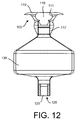
It should be appreciated that the devices described herein need not include a flow director 140 or a central core element 135. For example, FIG. 12 shows an implementation of a device 100 having an expandable reservoir 130 coupled on a proximal end to a retention structure 105 having a flange element 110, a penetrable barrier 115 positioned within an access port 111 and a distal extension 117. The expandable reservoir 130 is coupled on a distal end region to an outlet 125 having a drug release mechanism 120 positioned therein. However, there is no central core element 135 or flow director 140 incorporated. The material of the reservoir 130 can provide sufficient rigidity to the device such that it can be inserted through a penetration site along an axis of insertion A without collapsing in on itself or warping away from the insertion configuration or axis of insertion A. In some implementations, the material of the reservoir 130 is Polyethylene terephthalate (PET) and has a wall thickness in the range of about 0.0005 mm to about 0.05 mm such that the device has column strength and is generally rigid enough to insert into the eye without a central core element or flow director. In some implementations, the devices described herein can be implanted using a stylet or other rigid, longitudinal element that can be inserted within a region of the reservoir at the time of placement and then removed once the necessary column strength has been imparted and the device has penetrated through the sclera. The material of the reservoir 130 can also include Urethane, Nylon, Pebax, Polyurethanes, cross-linked polyethylene, FEP, PTFE, and similar materials and blends of materials. The materials may also include multiple layers of the above materials and other materials known in the art for manufacturing expandable elements.
As discussed above, the device can include a proximal retention structure 105 having a smooth protrusion or flange element 110 configured to remain generally external to the eye to aid in retention of the device 100 when the remainder of the device 100 is implanted intraocularly. In some implementations, the flange element 110 can be designed to provide an identifiable orientation of the device 100 for implanting in the eye such that the direction of expansion of an eccentrically expanding reservoir 130 is predictable and according to a desired orientation. The reservoir 130 once implanted within the vitreous 30 may not be directly visualized. Thus, an orientation indicator 150 on a portion of the device 100, such as the flange element 110, that can be visualized from outside the eye allows a user to know the expansion of the reservoir 130 will be in the correct plane. For example, FIG. 9 illustrates an orientation indicator 150 that is a dot or other visual indicator on an upper surface of the flange element 110. FIG. 13 illustrates an orientation indicator 150 that is a shape of the flange element 110 that indicates the orientation of the eccentric volume of the reservoir. For example, because the expandable reservoirs 130 can be designed to expand along a particular orientation relative to the longitudinal axis of the device and/or the insertion axis A, the relative orientation of that portion of the expandable reservoir 130 around the axis A can be critical in ensuring the device does not impinge on certain intraocular structures. In some implementations, the flange element 110 can incorporate a mark or other orientation indicator 150 on an upper surface 112 that is visible to a user to indicate orientation of reservoir filling. The orientation indicator 150 can be any of a variety of shapes, colors or combination of shapes and colors providing guidance regarding where the eccentric volume is located. Alternatively or additionally, the orientation indicator 150 can be the shape of the flange element 110 itself. For example, the flange element 110 can be shaped in such a way to provide directional guidance to a user for implantation of the device. The flange element 110 can have a variety of shapes such as an ovoid, elliptical, polygonal, triangular, or diamond shape or other shape such as an arrow having a side or angle or portion that indicates where the reservoir 130 is designed to have a greater expansion compared to another side of the reservoir 130. FIG. 13 illustrates a flange element 110 having a particular shape indicating orientation of the eccentric region of the reservoir 130. Upon filling, the orientation indicator 150 will indicate to a user the portion of the reservoir 130 that will expand away from one or more internal structures of the eye, such as the lens 22. It should be appreciated that the flange element 110 can be keyed or configured to couple with a fill device having keyed features that also provides visual feedback to the user regarding the orientation of the eccentric volume of the device prior to fill or refilling.
The devices described herein can incorporate expanding reservoirs that are also symmetrically distributed in the expanded configuration. As previously shown in FIGS. 2 and 3, the reservoir 130 can enlarge from the insertion configuration to an expanded configuration such that the volume of the reservoir 130 is symmetrically distributed about the longitudinal axis of the device as well as the axis of insertion A. In another implementation, the devices described herein can have expanded configurations that are symmetrically distributed, but the overall shape of the device itself can be formed into a curvilinear or other shape that is not aligned with the axis of insertion A. FIGS. 14-16 show an implementation of a device 200 having a reservoir 230 that expands generally symmetrically, but the implanted portion of the device 200 (i.e. the portion of the device 200 distal to the proximal retention structure 205) is shaped to curve away from the axis of insertion A. In some implementations, the portion of the device 200 within the vitreous 30 can extend generally perpendicular to the inner-facing surface 213 of the flange element 210 prior to implantation and filling. However, after implantation and filling, the device 200 can be formed or shaped such that the device 200 as a whole is off-axis relative to the insertion axis A. The device 200 is positioned generally such that even the distal-most region of the device 200 remains outside the visual axis of the eye and/or avoids contact with certain structures of the internal eye anatomy as described above. In some implementations, the device 200 in the expanded configuration is shapeable into a curvilinear shape that remains outside the visual axis of the eye. The device 200 can have an insertion configuration in which the reservoir 230 is collapsed around a longitudinal axis of the device into a minimally-invasive dimension for insertion through the sclera. After insertion through the sclera, the implanted portion of the device 200 distal to the retention structure 210 can be pre-shaped according to a desired angle and/or curve. For example, the region of the device 200 implanted in the vitreous 30 can be angled away from the insertion axis A. In another implementation, the region of the device 200 implanted in the vitreous 30 can be formed into a curve away from the insertion axis A, for example a curve that approaches the curve of the eye (see FIG. 16). Once the distal end region of the device 200 is shaped into the desired shape, the reservoir 230 can then be filled with therapeutic material to expand the reservoir 230 into the expanded configuration. The expanded configuration can be a symmetrically distributed expanded configuration such as that shown in FIGS. 14-16. Alternatively, the expanded configuration of the device 200 can be asymmetrically expanded or eccentrically expanded as described above such that the device 200 does not impinge upon certain internal structures of the eye and/or the visual field, visual axis, and/or optical axis. It should also be appreciated that the reservoir 230 can be a rigid, non-expandable configuration similar to those described in U.S. Pat. No. 8,277,830, which is incorporated by reference herein.
FIGS. 17-18 illustrate another implementation of a device 200 having a reservoir 230 that expands generally symmetrically. The implanted portion of the device 200 (i.e. the portion of the device 200 distal to the proximal retention structure 205) is shaped to curve away from the axis of insertion A upon filling. The device 200 can have an insertion configuration configured to be inserted through the sclera 24 into the vitreous 30 along the axis of insertion A and in a generally, minimally invasive manner. After insertion, the device 200 can be filled to expand the reservoir 230 into the expanded configuration. In the expanded configuration, the reservoir 230 can extend along a curvilinear path around a perimeter of the eye such that the device 200 does not impinge upon the visual field and/or the visual or optic axes 27, 29 (see FIG. 18). It should be appreciated that the device 200 can be pre-shaped and filled to expand the reservoir 230 afterwards. It should be appreciated that the drug release mechanism can be positioned within any of a variety of outlets of the device. For example, each of the reservoir portions extending away from the insertion axis can have an outlet each with a drug release mechanism positioned within or near the outlet or each of the reservoir portions can direct therapeutic agent through a single outlet, for example, an outlet positioned near a distal end of the device along the central axis of the device. Further, a wall of the reservoir can include highly calibrated perforations as the drug release mechanism.
Methods of Use
It should be appreciated that the treatment devices described herein can be used in a variety of locations and implanted in a variety of ways. The implantation method and use of the treatment devices described herein can vary depending on the type of treatment device being implanted and the intended location and drug for treatment. As will be described in more detail below, the treatment devices described herein can be primed, implanted, filled, refilled, and/or explanted using one or more devices.
In one implementation of treatment device implantation, a sclerotomy is created according to conventional techniques. The sclerotomy can be created posterior to an insertion site of the treatment device through the sclera 24 or the sclerotomy can be created directly above the insertion site of the post through the sclera 24. The conjunctiva 16 can be dissected and retracted so as to expose an area of the sclera 24. An incision in the conjunctiva 16 can be made remote from the intended insertion site of the treatment device. A scleral incision or puncture can be formed. The scleral incision or puncture can be made with a delivery device tool or using a distal tip of the treatment device, as described above. In some implementations, the treatment device is implanted using sutureless surgical methods and devices. In other implementations, the treatment device can be positioned sub-sclerally such as under a scleral flap. The post can be inserted into the eye (such as within the vitreous or the anterior chamber, etc.) until at least one of the outlets is positioned within or near the target delivery site and, if a flange element is present, until the inner-facing surface of the flange element can abut an outer surface of the eye. An additional fixation element can be used such as a suture or other element if needed following implantation of the treatment device in the eye. The treatment device can remain in position to deliver the one or more therapeutic agents to the eye for a period of time including, but not limited to 1, 2, 3, 4, 5, 10, 15, 20, 25 days or any number of days, months and year, up to at least about 3 years. After the therapeutic agent has been delivered for the desired period of time, the treatment device can be refilled for further delivery or removed.
Generally, the implementations of the treatment devices described herein contain drug solutions, drug suspensions and/or drug matrices. The treatment devices described herein can also contain therapeutic agents formulated as one or more solid drug core or pellets formulated to deliver the one or more therapeutic agents at therapeutically effective amounts for an extended period of time. The period of time over which the treatment device delivers therapeutically effective amounts can vary. In some implementations, the treatment device is implanted to provide a therapy over the effective life of the device such that refill of the device is not necessary.
FIGS. 19A-19D show a generalized tool 300 designed to prime, fill and/or refill the treatment devices described herein. The tool 300 can include a trocar introducer cannula 305 having an internal lumen through which an internal fill cannula 310 can extend. The introducer cannula 305 can extend through the penetrable element 115 in the proximal region of the device 100 until the distal end of the cannula 305 enters a proximal end region of the reservoir 130 (see FIG. 19B) and/or the proximal end of the central core element 135, if present. A region of the tool 300 can have a hard stop to prevent the distal tip 315 from extending too far into the reservoir 130. The internal fill cannula 310 can extend through the internal lumen of the introducer cannula 305 and into at least the proximal end region of the reservoir 130 (see FIG. 19C). The fill cannula 310 can extend further into the reservoir 130 towards a distal end region of the reservoir 130. The overall length of the fill cannula 310 can be selected based on the treatment device with which it will be used such that the fill cannula 310 can extend towards a distal end region of the reservoir 130 or the central core element 135, if present. Or if the device includes a flow director 140, the fill cannula 310 can have a length configured to extend through at least a region of the flow director 140. The fill cannula 310 can include a distal tip 315 that is blunted and has an opening 320 through which material may flow out of the fill cannula 310 (see FIG. 19D). The flow of material through the fill cannula 310 and out the opening 320 near the distal tip 315 allows for filling of the reservoir 130 in a bottom-up manner. A distal end region of the introducer cannula 305 can be configured to receive pre-existing material from the reservoir 130 such that it can be flushed out from the reservoir 130 upon filling with new material through the fill cannula 310. This in combination with a flow director 140 can increase refill efficiency. The tool 300 can incorporate one or more features of other refill devices described, for example, in U.S. Pat. Nos. 8,399,006; 8,623,395; U.S. Publication No. 2013/0324918; and U.S. Publication No. 2013/0165860, which are each incorporated in their entireties herein.
As described herein the treatment device can have an expandable reservoir formed of a generally non-compliant material. The reservoir can be folded down so that it fits within the internal volume of a delivery element and deployed reliably upon expansion. FIGS. 20A-20F show in schematic, top-down views an implementation of a treatment device 2100 in various stages of reservoir folding. The treatment device 2100 has a reservoir 2130 surrounding in an eccentric manner an axis A of the device. For the sake of simplicity, the folding of the reservoir 2130 will be described in terms of this axis A. The axis A can be coaxial with a central axis of the central core 2135, if present, although it should be appreciated that the central core element 2135 need not be present for the device to be folded as described below. The reservoir 2130 can be eccentric in that more of the expanded volume of the reservoir 2130 can be located on a first side of a plane drawn parallel to the axis A than on the opposite side of the plane such that the reservoir 2130 expands asymmetrically relative to the axis A. As shown in FIG. 20A, the asymmetric reservoir 2130 in an unfolded configuration can have a central region with an oval cross-sectional shape having a long axis LA and a short axis SA. An eccentric volume EV of the expanded portion of the reservoir 2130 can be located on a first side of the plane drawn parallel to the axis A. FIG. 20B shows a first step in folding the reservoir 2130 during which opposing regions of the reservoir 2130 along the long axis LA are urged inward towards one another creating a narrowed pinched region near a center of the reservoir volume. Opposing regions of the reservoir 2130 along the short axis SA can then be urged towards one another and toward the central axis A (see FIG. 20C). This configuration creates four folds or pleats 2137 a, 2137 b, 2137 c, 2137 d in the material of the reservoir 130, two on either side of the axis A extending outward along the long axis LA of the reservoir 130. Each pleat 2137 a, 2137 b, 2137 c, 2137 d can have a pleat end 2138 a, 2138 b, 2138 c, 2138 d. Adjoining pleats 2137 a, 2137 c can form a first trough 2139 a and adjoining pleats 2137 b, 2137 d can form a second trough 2139 b. The pleat ends 2138 a, 2138 c of a first two of the pleats 2137 a, 2137 c can be urged in a clockwise manner relative to the axis A toward the eccentric volume EV side and the pleat ends 2138 b, 2138 d of a second two of the pleats 2137 b, 2137 d can be urged in a counter-clockwise manner relative to the axis A toward the eccentric volume EV side forming a third trough 2139 c (see FIG. 20D). Pleat end 2138 a can be urged in the clockwise direction until pleat 2137 a folds down inside third trough 2139 c. Pleat 2137 b folds up against the central core 2135 onto the first trough 2139 a (FIG. 20E). Pleat end 2138 c is then urged in the counter-clockwise manner relative to the axis A until pleat 2137 c overlies pleat 2137 a. Pleat 2137 d folds up against central core 2135 onto second trough 2139 b. The asymmetric shape of the reservoir 2130 relative to the axis A of the device and the folding process results in pleats 2137 a, 2137 c forming longer “wings” of material relative to the pleat 2137 b, 2137 d. Further, this configuration results in pleat 2137 c overlying pleat 2137 a while the pleat 2137 b, 2137 d being pressed against the sides of the central core 2135. It should be appreciated, however that pleat 2137 c can fold into the third trough 2139 c and pleat 2137 a overlie pleat 2137 c. Generally, two of the pleats that are longer (i.e. the pleats on the eccentric volume EV side of the reservoir) can overlap at least a portion of their length while two of the pleats that are shorter (i.e. the pleats on the opposite side) do not overlap. It should be appreciated that the folding described above can also be applied to compliant materials in as much as necessary to deal with any excess material that may be needed to produce the asymmetric region of the reservoir.
The treatment devices described herein can be primed and inserted using one or more devices described in U.S. Publication No. 2015/0080846, which is incorporated by reference herein. In some implementations, the folded down treatment device 2100 can be held within a priming tool 2200. FIGS. 21A-21B show an unloaded priming tool 2200 and a close-up of the priming tool 2200 loaded with a treatment device 2100, respectively. The priming tool 2200 can be a separate tool or can be integrated with a delivery system used to fill and/or implant the treatment device 2100. In some implementations, a user can hold the priming tool 2200 by handles 2205 on a proximal end of the tool 2200 and operatively coupled to opposing clamshells 2210 on a distal end. The handles 2205 can have a reverse tweezer type of actuation mechanism such that the clamshells 2210 are biased in a closed position against one another and a squeeze inward moves the opposing clamshells 2210 a distance away from one another. The clamshells 2210 each can have a recessed internal geometry configured to contain at least a portion of the treatment device 2100. For example, one of the clamshells 2210 can have a first recess portion and the second of the clamshells 2210 can have a second recess portion that when the clamshells 2210 are in a closed position together the recess portions form a cavity 2215 having a shape substantially the same as an outer contour of the treatment device 2100. The priming tool 2200 can hold the treatment device 2100 within the cavity 2215 formed by the opposed recess portions and the folded pleats of the reservoir 2130 can be constrained and prevented from expanding, particularly during priming as will be described in more detail below. The clamshells 2210 can be formed of a substantially clear material for optimal viewing and/or visual indications during priming of the treatment device 2100.
The priming tool 2200 can further include a channel 2220 between the clamshells 2210 (see FIG. 21B) such that an upper surface of the treatment device 2100 can be accessed when the treatment device 2100 is held within the priming tool 2200. For example, the channel 2220 allows for insertion of a needle through the septum of the treatment device 2100 to prime and/or fill the device prior to insertion into a patient as shown in FIG. 21C. The channel 2220 of the priming tool 2200 can incorporate one or more features that provide proper alignment and access between the needle and the septum of the treatment device.
The treatment device 2100 can be primed using a priming needle. The priming needle can be part of an insertion tool or can be a separate priming needle of a separate tool. The priming needle can penetrate the septum of the treatment device 2100 constrained within the cavity 2215 between the opposing clamshells 2210 of the priming tool 2200. The priming needle can be coupled to a syringe filled with an amount of priming fluid. The syringe can be actuated such as via a plunger to inject fluid into the constrained device to purge air out of the device 2100. The air can be purged through a porous structure in the treatment device 2100, such as the drug release mechanism at a distal end of the treatment device 210, as the injected priming fluid is injected into the reservoir 2130 of the device 2100. The priming fluid can be a fluid such as saline or can be a drug solution to be delivered to the patient. Because the treatment device 2100 is constrained between the clamshells 2210 priming does not discernibly expand the reservoir 2130.
FIGS. 22A-22B shows an implementation of an insertion tool 2300 for use with the priming tool 2200. It should be appreciated that although the insertion tool 2300 is described as being separate from the priming tool 2200 and/or the priming needle, the various tools can be integrated within a single device or system that serves the various functions of holding, priming, and inserting. The insertion tool 2300 can include a proximal handle 2305 and a distal needle post 2310 having a pointed tip 2315, and optionally a seating element 2325 positioned between the needle post 2310 and the handle 2305. The needle post 2310 can be inserted through channel 2220 of the priming tool 220 and directed toward an upper surface of the treatment device 2100 held between the clamshells 2210. The needle post 2310 can penetrate through the septum of the treatment device 2100 held within the clamshells 2210 such that the device 2100 is secured to the insertion tool 2300. Once the treatment device 2100 is primed and secured to the insertion tool 2300, the priming tool 2200 can be actuated to move the clamshells 2210 away from one another releasing the treatment device 2100 from within the cavity 2215 therebetween (see FIG. 21D).
Again with respect to FIG. 22A-22B, the insertion tool 2300 can incorporate one or more body geometries, visual indicators, and/or mechanical keying features that allow for proper alignment upon insertion of the needle post 2310 through the septum of the treatment device 2100 held within the priming tool 2200. For example, a portion of the insertion tool 2300 can include a raised, mechanical key 2301 that extends outward from a cylindrical surface of the tool. The key 2301 can slide into a correspondingly shaped slot 2302 in a portion of the priming tool 2200. The key 2301 slides through the slot 2302 as the needle penetrates the septum only when the insertion tool 2300 is in a certain orientation relative to the priming tool 2200. The key 2301 prevents the needle from penetrating the septum in any other orientation as the key 2301 would abut the priming tool 2200 as the needle post 2310 inserts through the channel 2220. The insertion tool 2300 can also incorporate one or more visual markers to guide a user to position the insertion tool 2300 relative to the treatment device 2100 in a desired or known orientation. As such, once the treatment device 2100 is penetrated by the insertion tool 2300 the operator can be made generally aware of the relative orientation of the treatment device 2100 being held by the insertion tool 2300 and will know in which direction the eccentric volume of the reservoir 2130 will expand and can insert the treatment device 2100 through the incision accordingly.
Although the treatment device 2100 held by the insertion tool 2300 can be inserted through a puncture or an incision in the target region in a known manner, the orientation of the treatment device 2100 can be rotationally adjusted once inserted, if desired. In some implementations, the insertion tool 2300 can incorporate one or more features designed specifically to rotate the treatment device 2100 around the axis of insertion A. As mentioned above, the insertion tool 2300 can include a seating element 2325 configured to urge the treatment device 2100 through the incision. The seating element 2325 can have a distal end 2320 shaped to mate with and apply torque to the treatment device 2100. As best shown in FIGS. 23A-23E, the distal end 2320 of the seating element 2325 can include a cavity 2330 sized and shaped to receive at least a portion of the flange element 2110 at a proximal end of the treatment device 2100. As described elsewhere herein, the proximal flange element 2110 of the treatment device 2100 can have a specific geometry, for example a long axis and a short axis or an asymmetrical shape. The distal end 2320 of the insertion tool 2300 can slide down over the flange element 2110 such that the flange element 2110 inserts within the cavity 2330 such that the flange element 2110 and thus the treatment device 2100 rotates upon rotation of the insertion tool 2300. Additionally, the distal end 2320 can include a pair of edge features 2335 located on opposite sides of the cavity 2330 that can make contact with portions of the flange element 2110 to further aid in the rotation of the treatment device 2100 in a clockwise or counter-clockwise direction around the axis A. It should be appreciated that the seating element 2325 can also have a flat face at its distal-most end configured to abut an upper surface of the treatment device 2100 during insertion.
The seating element 2325 and/or the needle post 2310 can be movable relative to the handle 2305, for example, rotated as described above, advanced in a distal direction, and/or withdrawn in a proximal direction. Alternatively, the seating element 2325 and needle post 2310 can be fixed relative to the handle 2305 such that the entire insertion tool 2300 is moved by the operator in a clockwise, counter-clockwise, distal or proximal direction relative to a patient to seat the therapeutic device. Once the treatment device 2100 is properly oriented within the target treatment location, the seating element 2325 can be used to seat the treatment device 2100 into its final position in the incision with a single advancing motion.
FIGS. 24A-24F illustrate an implementation of an insertion tool 2300 having a handle 2305, a needle post 2310, a seating element 2325, an actuator 2345, and opposing end effectors 2350. The needle post 2310 and seating element 2325 can extend coaxially with each other as well as with the handle 2305 and the end effectors 2350. As described above, the treatment device 2100 can be held by the insertion tool 2300 such that the needle post 2310 extends through the septum of the device 2100. The needle post 2310 can be visible through an opening 2360 formed by the opposing end effectors 2350 (see FIG. 24D). The end effectors 2350 of the insertion tool 2300 can clamp onto the proximal end of the treatment device 2100. When the end effectors 2350 are closed around the flange element 2110 of the treatment device 2100, their distal ends 2355 wrap around a region of the treatment device 2100 near an underneath side of the flange element 2110. However, the thickness of these distal ends 2355 wrapping around the underneath side of the flange element 2110 fills this region of the treatment device 2100 that would otherwise be surrounded by the tissue through which the device 2100 is implanted if the device 2100 were fully seated within the incision. Thus, the end effectors 2350 can be urged away from one another (see FIG. 24E), for example by the sliding actuator 2345 as the device 2100 is seated in place. The seating element 2325 extending coaxially within the end effectors 2350 and over the needle post 2310 can be urged distally to press against the upper surface of the flange element 2110 of the treatment device 2100 (see FIG. 24F). The treatment device 2100 can thus be urged down into and seat within the incision. The movement of the seating element 2325 in a distal direction and the end effectors 2350 in outward direction can occur substantially simultaneously upon a single actuation of the actuator 2345 or in a step-wise manner such that the end effectors 2350 move away from the flange element 2110 before the seating element 2325 extends in a distal direction.
In some implementations, the seating element 2325 can have an outer surface that is shaped to engage an inner surface of the end effectors 2350 to urge them in an outward direction as the seating element 2325 is advanced distally through the end effectors 2350 to seat the treatment device 2100. As best shown in FIG. 24G, the end effectors 2350 can be coupled at their proximal ends to the handle by a hinge pin such that the pair of end effectors 2350 can pivot towards and away from the axis A and each other. The seating element 2325 can extend distally between the end effectors 2350 coaxial to axis A within a central channel of the end effectors 2350. The central channel of the end effectors 2350 can include a feature 2365 such as a cam configured to engage a corresponding surface feature 2360 on an outer surface of the seating element 2325 extending through the central channel of the end effectors 2350. As such, when the seating element 2325 is urged in a forward, linear direction by the actuator 2345, the feature 2360 on the outer surface of the seating element 2325 engages the feature 2365 of the end effectors 2350 urging the end effectors 2350 to pivot outward away from one another. This releases the flange element 2110 of the treatment device 2100 being held by the distal ends of the end effectors 2350 such that the flange element 2110 can be seated within the incision in an unobstructed manner. The actuator 2345 can be coupled to the seating element 2325 by a retention spring that presses against the actuator 2345 and keeps the end effectors 2350 biased in a closed position around the treatment device 2100. The retention spring can also keep the needle post 2310 from puncturing the septum of the treatment device 2100 prior to implantation. Thus, this implementation of an insertion tool can hold the treatment device 2100 by the flange element 2110 by the distal ends of the end effectors 2350 and bias the needle post 2310 and the seating element 2325 in a proximal position until actuated to seat the device 2100.
The reservoir 2130 can be filled and expanded following implantation and seating of the device. However, it should be appreciated that the reservoir 2130 can be filled prior to, during, or after final seating the treatment device 2100 fully within the incision as will be described in more detail below. In some implementations, the fill needle 2500 can be a 30 gauge needle that has a hub providing visual feedback via its fluid return path when the treatment device 2100 has been filled (see FIG. 25). For example, the fill needle 2500 can include a transparent or translucent chamber for viewing return fluid. The fill needle 2500 can also include one or more return fluid path holes. The fill needle can be used to inject therapeutic fluid into the device 2100 until the prime fluid is removed from the treatment device 2100. The reservoir 2130 expands as the device 2100 is filled with fluid. The device 2100 can be slightly overfilled to ensure maximum expansion.
In some implementations, the fill needle 2500 can be the same as the prime needle used to prime and purge air from the treatment device as described above. The fill needle 2500 can also be the same as the needle on the insertion device 2300 used to hold and deliver the treatment device into position as described above. It should be appreciated that the priming needle, needle post 2310, and fill needle 2500 can each be separate devices such that three penetrations of the septum in the treatment device 2100 occurs during prime, insertion and filling. It should be appreciated that the priming needle, needle post 2310, and fill needle 2500 can be the same needle such that a single penetration of the septum is performed during prime, insertion and filling. Alternatively, the prime needle and needle post 2310 can be the same component and the fill needle 2500 separate component or the prime needle a separate component and the needle post 2310 and the fill needle 2500 the same component such that only two penetrations are needed to prime, insert, and fill the therapeutic device initially. It should also be appreciated that the treatment devices described herein can be refilled after a period of time. The septum of the treatment device can be penetrated during refill with a refill needle, for example such as that described in U.S. Pat. No. 9,033,911 or in U.S. Publication No. 2013/0165860, which are each incorporated by reference herein. The refill needle and the fill needle can be the same type of needle or can be distinct from one another. For example, the fill needle may or may not incorporate features to visualize filling whereas the refill needle does incorporate such features.
Once the expanded volume of the implanted reservoir is achieved, the device can be refilled at predictable intervals (e.g. every 3, 4, 5, 6 months or as along as every 12 months). However, changing the volume of the expanded device once implanted in the eye may not be desirable (e.g. movement in the eye once implanted may lead to potential trauma to surrounding structures or fluctuations in intraocular pressure) and is thus something to be avoided. The treatment devices described herein once implanted and expanded can maintain a consistent volume such that the outer diameter or contour of the reservoir does not change substantially throughout the use of the device and regardless of fill status. Further, the treatment devices described herein can maintain the same expanded shape even while fluid is being injected into the reservoir and/or while fluid is being removed from the reservoir (e.g. using the refill needle with or without flow directors). For example, drug passively diffuses through the porous drug delivery mechanism and out of the expanded reservoir over time. Despite this drug release into the eye, the expanded reservoir can remain filled with fluid, for example, fluid that enters the reservoir from the vitreous and drug formulation fluid remaining in the reservoir. The reservoir material can be formed of a substantially non-compliant material that tends to maintain its physical structure regardless of whether the interior of the reservoir is filled with drug. Further, refill of the treatment devices described herein can be performed such that a negative pressure and/or a positive pressure does not build within it. The refill and exchange devices used can incorporate features to avoid aspirating or evacuating the fluid within the reservoir and instead exchange the fluid while maintaining a substantially constant internal pressure. The treatment devices as well can incorporate one or more features to encourage this pressure-neutral exchange. For example, the treatment device can incorporate a central core element extending through the volume of the reservoir that has a wall surrounding a lumen, an inlet to the lumen, an outlet from the lumen, and one or more openings extending through the wall of the central core element between the inlet and the outlet. The lumen can be in fluid communication with the volume of the reservoir via the one or more openings. In some implementations, the one or more openings are located along the wall of the central core element to encourage exchange of new drug formulation fluid with the fluid remaining within the reservoir. For example, a first opening can be located near a distal end region of the central core element such that upon insertion of the refill/exchange needle through the inlet new drug formulation is delivered near this first opening. At least a second opening can be located near a proximal end region of the central core element. The fluid remaining within the reservoir that is to be exchanged for the new drug formulation can exit the reservoir volume through the second opening(s). An outlet lumen of the refill/exchange needle can be positioned near this second opening such that the fluid is removed from the treatment device through the outlet lumen. This arrangement of inlet and outlet openings in the central core element can encourage exchange of fluids (e.g. new formulation for old formulation) without mixing and without impacting the pressure within the reservoir volume that could impact the outer diameter or contour of the expandable reservoir. Further, the central core element can protect the material of the reservoir as the refill needle is inserted through the inlet of the central core element. The insertion configuration of the treatment device is when the non-compliant material of the reservoir is collapsed around the central core and forms a first three-dimensional shape prior to filling the volume with the one or more therapeutic agents. The non-compliant material of the reservoir is enlarged away from the central core element forming a second three-dimensional shape upon filling the volume with the one or more therapeutic agents when in an expanded configuration. This second three-dimensional shape achieved upon filling is then maintained throughout the life of the treatment device regardless of fill status or whether or not fluid is being added to the reservoir or taken from the reservoir.
The treatment devices described herein need not be removed and can remain in place indefinitely so long as therapeutically effective and beyond. However, the treatment device 2100 can be explanted (i.e. removed from the target location). Because the reservoir 2130 is expanded to a profile that is greater than the insertion profile, the reservoir 2130 is preferably unexpanded prior to removal. An aspiration needle can be connected, such as by tubing or other connector, to an aspiration device. The aspiration device can be a vacuum-lock syringe that creates a vacuum and provides suction for aspiration from the reservoir 2130. The syringe can be actuated by a luer lock lever, for example, to aspirate the reservoir 2130 of the treatment device 2100 and remove remaining contents. This system can be used to aspirate the contents of the reservoir 2130 for refill of the device and/or for removal of the device. The contents aspirated can be made visible through the aspiration device for visual feedback on completion of the aspiration process. Aspiration can collapse the expanded reservoir to a low profile such that the device 2100 can be explanted through the incision cavity. Smaller profile can reduce the removal force required as well as limit contact with internal tissues that can cause bleeding and damage. The aspirated and collapsed treatment devices described herein can be removed according to the methods and using the devices described in U.S. Patent Publication No. 2015/0080846, which is incorporated by reference herein. A long cannula or stylet can aid in stabilizing the therapeutic device during explanation, for example, if the device 2100 has no central core element 135, during evacuation of the reservoir 130 to a smaller outer diameter for ease of removal during explant.
Indications
The treatment devices described herein can be used to treat and/or prevent a variety of other ocular conditions besides glaucoma, including but not limited to dry or wet age-related macular degeneration (AMD), neuroprotection of retinal ganglion cells, cataract or presbyopia prevention, cancers, angiogenesis, neovascularization, choroidal neovascularization (CNV) lesions, retinal detachment, proliferative retinopathy, proliferative diabetic retinopathy, degenerative disease, vascular diseases, occlusions, infection caused by penetrating traumatic injury, endophthalmitis such as endogenous/systemic infection, post-operative infections, inflammations such as posterior uveitis, retinitis or choroiditis and tumors such as neoplasms and retinoblastoma. Still further conditions that can be treated and/or prevented using the devices and methods described herein, include but are not limited to hemophilia and other blood disorders, growth disorders, diabetes, leukemia, hepatitis, renal failure, HIV infection, hereditary diseases such as cerebrosidase deficiency and adenosine deaminase deficiency, hypertension, septic shock, autoimmune diseases such as multiple sclerosis, Graves' disease, systemic lupus erythematosus and rheumatoid arthritis, shock and wasting disorders, cystic fibrosis, lactose intolerance, Crohn's disease, inflammatory bowel disease, gastrointestinal or other cancers, degenerative diseases, trauma, multiple systemic conditions such as anemia.
Therapeutics
Examples of therapeutic agents that may be delivered by the treatment devices described herein and/or are described in the applications incorporated by reference herein are provided below and in Table 1, which is incorporated herein in its entirety.
Therapeutics that can be delivered from the devices described herein include but are not limited to Triamcinolone acetonide, Bimatoprost (Lumigan) or the free acid of bimatoprost, latanoprost or the free acid or salts of the free acid of latanoprost, Ranibizumab (Lucentis™) Travoprost (Travatan, Alcon) or the free acid or salts of the free acid of travoprost, Timolol (Timoptic, Merck), Levobunalol (Betagan, Allergan), Brimonidine (Alphagan, Allergan), Dorzolamide (Trusopt, Merck), Brinzolamide (Azopt, Alcon). Additional examples of therapeutic agents that may be delivered by the therapeutic device include antibiotics such as tetracycline, chlortetracycline, bacitracin, neomycin, polymyxin, gramicidin, cephalexin, oxytetracycline, chloramphenicol kanamycin, rifampicin, ciprofloxacin, tobramycin, gentamycin, erythromycin and penicillin; antifungals such as amphotericin B and miconazole; anti-bacterials such as sulfonamides, sulfadiazine, sulfacetamide, sulfamethizole and sulfisoxazole, nitrofurazone and sodium propionate; antivirals such as idoxuridine, trifluorotymidine, acyclovir, ganciclovir and interferon; antiallergenics such as sodium cromoglycate, antazoline, methapyriline, chlorpheniramine, pyrilamine, cetirizine and prophenpyridamine; anti-inflammatories such as hydrocortisone, hydrocortisone acetate, dexamethasone, dexamethasone 21-phosphate, fluocinolone, medrysone, prednisolone, prednisolone 21-phosphate, prednisolone acetate, fluoromethalone, betamethasone, and triamcinolone; non-steroidal anti-inflammatories such as salicylate, indomethacin, ibuprofen, diclofenac, flurbiprofen and piroxicam; decongestants such as phenylephrine, naphazoline and tetrahydrozoline; miotics and anticholinesterases such as pilocarpine, salicylate, acetylcholine chloride, physostigmine, eserine, carbachol, diisopropyl fluorophosphate, phospholine iodide and demecarium bromide; mydriatics such as atropine sulfate, cyclopentolate, homatropine, scopolamine, tropicamide, eucatropine and hydroxyamphetamine; sypathomimetics such as epinephrine; antineoplastics such as carmustine, cisplatin and fluorouracil; immunological drugs such as vaccines and immune stimulants; hormonal agents such as estrogens, estradiol, progestational, progesterone, insulin, calcitonin, parathyroid hormone and peptide and vasopressin hypothalamus releasing factor; beta adrenergic blockers such as timolol maleate, levobunolol HCl and betaxolol HCl; growth factors such as epidermal growth factor, fibroblast growth factor, platelet derived growth factor, transforming growth factor beta, somatotropin and fibronectin; carbonic anhydrase inhibitors such as dichlorophenamide, acetazolamide and methazolamide and other drugs such as prostaglandins, antiprostaglandins and prostaglandin precursors. Other therapeutic agents known to those skilled in the art which are capable of controlled, sustained release into the eye in the manner described herein are also suitable for use in accordance with embodiments of the devices described herein.
The therapeutic agent can also include one or more of the following: Abarelix, Abatacept, Abciximab, Adalimumab, Aldesleukin, Alefacept, Alemtuzumab, Alpha-1-proteinase inhibitor, Alteplase, Anakinra, Anistreplase, Antihemophilic Factor, Antithymocyte globulin, Aprotinin, Arcitumomab, Asparaginase, Basiliximab, Becaplermin, Bevacizumab, Bivalirudin, Botulinum Toxin Type A, Botulinum Toxin Type B, Capromab, Cetrorelix, Cetuximab, Choriogonadotropin alfa, Coagulation Factor IX, Coagulation factor VIIa, Collagenase, Corticotropin, Cosyntropin, Cyclosporine, Daclizumab, Darbepoetin alfa, Defibrotide, Denileukin diftitox, Desmopressin, Dornase Alfa, Drotrecogin alfa, Eculizumab, Efalizumab, Enfuvirtide, Epoetin alfa, Eptifibatide, Etanercept, Exenatide, Felypressin, Filgrastim, Follitropin beta, Galsulfase, Gemtuzumab ozogamicin, Glatiramer Acetate, Glucagon recombinant, Goserelin, Human Serum Albumin, Hyaluronidase, Ibritumomab, Idursulfase, Immune globulin, Infliximab, Insulin Glargine recombinant, Insulin Lyspro recombinant, Insulin recombinant, Insulin, porcine, Interferon Alfa-2a, Recombinant, Interferon Alfa-2b, Recombinant, Interferon alfacon-1, Interferonalfa-n1, Interferon alfa-n3, Interferon beta-1b, Interferon gamma-1b, Lepirudin, Leuprolide, Lutropin alfa, Mecasermin, Menotropins, Muromonab, Natalizumab, Nesiritide, Octreotide, Omalizumab, Oprelvekin, OspA lipoprotein, Oxytocin, Palifermin, Palivizumab, Panitumumab, Pegademase bovine, Pegaptanib, Pegaspargase, Pegfilgrastim, Peginterferon alfa-2a, Peginterferon alfa-2b, Pegvisomant, Pramlintide, Ranibizumab, Rasburicase, Reteplase, Rituximab, Salmon Calcitonin, Sargramostim, Secretin, Sermorelin, Serum albumin iodonated, Somatropin recombinant, Streptokinase, Tenecteplase, Teriparatide, Thyrotropin Alfa, Tositumomab, Trastuzumab, Urofollitropin, Urokinase, or Vasopressin.
The therapeutic agent can include one or more of compounds that act by binding members of the immunophilin family of cellular proteins. Such compounds are known as “immunophilin binding compounds” Immunophilin binding compounds include but are not limited to the “limus” family of compounds. Examples of limus compounds that may be used include but are not limited to cyclophilins and FK506-binding proteins (FKBPs), including sirolimus (rapamycin) and its water soluble analog SDZ-RAD, tacrolimus, everolimus, pimecrolimus, CCI-779 (Wyeth), AP23841 (Ariad), and ABT-578 (Abbott Laboratories). The limus family of compounds may be used in the compositions, devices and methods for the treatment, prevention, inhibition, delaying the onset of, or causing the regression of angiogenesis-mediated diseases and conditions of the eye, including choroidal neovascularization. The limus family of compounds may be used to prevent, treat, inhibit, delay the onset of, or cause regression of AMD, including wet AMD. Rapamycin may be used to prevent, treat, inhibit, delay the onset of, or cause regression of angiogenesis-mediated diseases and conditions of the eye, including choroidal neovascularization. Rapamycin may be used to prevent, treat, inhibit, delay the onset of, or cause regression of AMD, including wet AMD.
The therapeutic agent can include one or more of: pyrrolidine, dithiocarbamate (NF.kappa.B inhibitor); squalamine; TPN 470 analogue and fumagillin; PKC (protein kinase C) inhibitors; Tie-1 and Tie-2 kinase inhibitors; proteosome inhibitors such as Velcade™ (bortezomib, for injection; ranibuzumab (Lucentis™) and other antibodies directed to the same target; pegaptanib (Macugen™); vitronectin receptor antagonists, such as cyclic peptide antagonists of vitronectin receptor-type integrins; .alpha.-v/.beta.-3 integrin antagonists; .alpha.-v/.beta.-1 integrin antagonists; thiazolidinediones such as rosiglitazone or troglitazone; interferon, including.gamma.-interferon or interferon targeted to CNV by use of dextran and metal coordination; pigment epithelium derived factor (PEDF); endostatin; angiostatin; tumistatin; canstatin; anecortave acetate; acetonide; triamcinolone; tetrathiomolybdate; RNA silencing or RNA interference (RNAi) of angiogenic factors, including ribozymes that target VEGF expression; Accutane™ (13-cis retinoic acid); ACE inhibitors, including but not limited to quinopril, captopril, and perindozril; inhibitors of mTOR (mammalian target of rapamycin); 3-aminothalidomide; pentoxifylline; 2-methoxyestradiol; colchicines; AMG-1470; cyclooxygenase inhibitors such as nepafenac, rofecoxib, diclofenac, rofecoxib, NS398, celecoxib, vioxx, and (E)-2-alkyl-2(4-methanesulfonylphenyl)-1-phenylethene; t-RNA synthase modulator; metalloprotease 13 inhibitor; acetylcholinesterase inhibitor; potassium channel blockers; endorepellin; purine analog of 6-thioguanine; cyclic peroxide ANO-2; (recombinant) arginine deiminase; epigallocatechin-3-gallate; cerivastatin; analogues of suramin; VEGF trap molecules; apoptosis inhibiting agents; Visudyne™, snET2 and other photo sensitizers, which may be used with photodynamic therapy (PDT); inhibitors of hepatocyte growth factor (antibodies to the growth factor or its receptors, small molecular inhibitors of the c-met tyrosine kinase, truncated versions of HGF e.g. NK4).
The therapeutic agent can include inhibitors of VEGF receptor kinase; inhibitors of VEGFA, VEGFC, VEGFD, bFGF, PDGF, Ang-2, PDGFR, cKIT, FGF, BDGF, mTOR, αvβ3, αvβ 5, α5β1 integrin, and alpha2 adrenergic receptor; inhibitors of complement factor B (e.g. TA106), complement factor D (CFD) (Lampalizumab/TNX-234), C3 (e.g. APL-2, novel compstatin analogs), C5 (e.g. Eculizumab, Zimura, ARC1905, ALN-CC5), C5a (e.g. JPE-1375), and tubulin; AAV-CD56 The therapeutic agent can also include Complement Factor H (CFH), engineered mini-CFH, or recombinant CFH (rCFH).
The therapeutic agent can include a combination with other therapeutic agents and therapies, including but not limited to agents and therapies useful for the treatment of angiogenesis or neovascularization, particularly CNV. Non-limiting examples of such additional agents and therapies include pyrrolidine, dithiocarbamate (NF.kappa.B inhibitor); squalamine; TPN 470 analogue and fumagillin; PKC (protein kinase C) inhibitors; Tie-1 and Tie-2 kinase inhibitors; inhibitors of VEGF receptor kinase; proteosome inhibitors such as Velcade™ (bortezomib, for injection; ranibizumab (Lucentis™) and other antibodies directed to the same target; pegaptanib (Macugen™); vitronectin receptor antagonists, such as cyclic peptide antagonists of vitronectin receptor-type integrins; .alpha.-v/.beta.-3 integrin antagonists; .alpha.-v/.beta.-1 integrin antagonists; thiazolidinediones such as rosiglitazone or troglitazone; interferon, including .gamma-interferon or interferon targeted to CNV by use of dextran and metal coordination; pigment epithelium derived factor (PEDF); endostatin; angiostatin; tumistatin; canstatin; anecortave acetate; acetonide; triamcinolone; tetrathiomolybdate; RNA silencing or RNA interference (RNAi) of angiogenic factors, including ribozymes that target VEGF expression; Accutane™ (13-cis retinoic acid); ACE inhibitors, including but not limited to quinopril, captopril, and perindozril; inhibitors of mTOR (mammalian target of rapamycin); 3-aminothalidomide; pentoxifylline; 2-methoxyestradiol; colchicines; AMG-1470; cyclooxygenase inhibitors such as nepafenac, rofecoxib, diclofenac, rofecoxib, NS398, celecoxib, vioxx, and (E)-2-alkyl-2(4-methanesulfonylphenyl)-1-phenylethene; t-RNA synthase modulator; metalloprotease 13 inhibitor; acetylcholinesterase inhibitor; potassium channel blockers; endorepellin; purine analog of 6-thioguanine; cyclic peroxide ANO-2; (recombinant) arginine deiminase; epigallocatechin-3-gallate; cerivastatin; analogues of suramin; VEGF trap molecules; inhibitors of hepatocyte growth factor (antibodies to the growth factor or its receptors, small molecular inhibitors of the c-met tyrosine kinase, truncated versions of HGF e.g. NK4); apoptosis inhibiting agents; Visudyne™, snET2 and other photo sensitizers with photodynamic therapy (PDT); and laser photocoagulation.
Prostaglandin analogues (PGAs) can be used to increase outflow of aqueous through the ciliary body and/or the trabecular meshwork including travaprost (0.004%), bimatoprost (0.03%, 0.01%), tafluprost (0.0015%), and latanoprost (0.005%). Beta blockers can be used to reduce aqueous fluid production by the ciliary body. Drugs in this class include timolol (0.5%). Carbonic anhydrase inhibitors can be used to reduce aqueous fluid production by the ciliary body as well. Drugs in this class include brinzolamide (1%), methazolamide, dorzolamide (2%), and acetazolamide. Alpha antagonists can be used to reduce aqueous fluid production by the ciliary body and increase outflow through the trabecular meshwork. Thus, the drug targets tissues located in both the anterior chamber and the posterior chamber and as such the devices can be implanted in either location to achieve a therapeutic result. Drugs in this class include brimonidine (0.1%, 0.15%) and apraclonidine (0.5%, 1.0%). Commercially available combinations of therapeutics considered herein include COMBIGAN® (brimonidine tartrate/timolol maleate ophthalmic solution; Allergan), and COSOPT® (dorzolamide hydrochloride-timolol maleate ophthalmic solution; Merck). Further, other sustained release therapeutics considered herein include subconjunctival latanoprost (Psivida/Pfizer), intracameral bimatoprost (Allergan), and intravitreal brimonidine (Allergan).
Various pharmaceutically acceptable carriers for the therapeutic agents described herein can include such as, for example, solids such as starch, gelatin, sugars, natural gums such as acacia, sodium alginate and carboxymethyl cellulose; polymers such as silicone rubber; liquids such as sterile water, saline, dextrose, dextrose in water or saline; condensation products of castor oil and ethylene oxide, liquid glyceryl triester of a lower molecular weight fatty acid; lower alkanols; oils such as corn oil, peanut oil, sesame oil, castor oil, and the like, with emulsifiers such as mono- or di-glyceride of a fatty acid, or a phosphatide such as lecithin, polysorbate 80, and the like; glycols and polyalkylene glycols; aqueous media in the presence of a suspending agent, for example, sodium carboxymethylcellulose, sodium hyaluronate, sodium alginate, poly(vinyl pyrrolidone) and similar compounds, either alone, or with suitable dispensing agents such as lecithin, polyoxyethylene stearate and the like. The carrier may also contain adjuvants such as preserving, stabilizing, wetting, emulsifying agents or other related materials
Materials
Generally, the components of the devices described herein are fabricated of materials that are biocompatible and preferably insoluble in the body fluids and tissues that the device comes into contact with. The materials generally do not cause irritation to the portion of the eye that it contacts. Materials may include, by way of example, various polymers including, for example, silicone elastomers and rubbers, polyolefins, polyurethanes, acrylates, polycarbonates, polyamides, polyimides, polyesters, and polysulfones. One or more components of the devices described herein can be fabricated of a permeable material including, but not limited to, polycarbonates, polyolefins, polyurethanes, copolymers of acrylonitrile, copolymers of polyvinyl chloride, polyamides, polysulphones, polystyrenes, polyvinyl fluorides, polyvinyl alcohols, polyvinyl esters, polyvinyl butyrate, polyvinyl acetate, polyvinylidene chlorides, polyvinylidene fluorides, polyimides, polyisoprene, polyisobutylene, polybutadiene, polyethylene, polyethers, polytetrafluoroethylene, polychloroethers, polymethylmethacrylate, polybutylmethacrylate, polyvinyl acetate, nylons, cellulose, gelatin, silicone rubbers and porous rubbers. One or more components of the devices described herein can be fabricated of a nonbiodegradable polymer, including but not limited to polymethylmethacrylate, a silicone elastomer, or silicone rubber. Other suitable non-erodible, biocompatible polymers which may be used in fabricating the devices described herein may include polyolefins such as polypropylene and polyethylene, homopolymers, and copolymers of vinyl acetate such as ethylene vinyl acetate copolymer, polyvinylchlorides, homopolymers and copolymers of acrylates such as polyethylmethacrylate, polyurethanes, polyvinylpyrrolidone, 2-pyrrolidone, polyacrylonitrile butadiene, polycarbonates, polyamides, fluoropolymers such as polytetrafluoroethylene and polyvinyl fluoride, polystyrenes, homopolymers and copolymers of styrene acrylonitrile, cellulose acetate, homopolymers and copolymers of acrylonitrile butadiene styrene, polymethylpentene, polysulfones, polyesters, polyimides, natural rubber, polyisobutylene, polymethylstyrene and other similar non-erodible biocompatible polymers.
One or more of the components of the devices described herein can be fabricated of a substantially non-compliant material that can be expanded to a particular shape. One or more of the components of the devices described herein can be fabricated of a rigid, non-pliable material. One or more of the components of the devices described herein can be fabricated of a shape memory material and/or superelastic material including, but not limited to shape memory alloys (SMA) like Nitinol (Ni—Ti alloy) and shape memory polymers (SMP) like AB-polymer networks based on oligo(e-caprolactone) dimethacrylates and n-butyl acrylate. Shape memory alloys generally have at least two phases: (1) a martensite phase, which has a relatively low tensile strength and which is stable at relatively low temperatures, and (2) an austenite phase, which has a relatively high tensile strength and which is stable at temperatures higher than the martensite phase. The shape memory characteristics are imparted on the material by heating the material to a temperature above the temperature at which the austenite phase is stable. While the material is heated to this temperature, the device is held in the “memory shape”, which is shape that is desired to be “remembered”.
While this specification contains many specifics, these should not be construed as limitations on the scope of what is claimed or of what may be claimed, but rather as descriptions of features specific to particular embodiments. Certain features that are described in this specification in the context of separate embodiments can also be implemented in combination in a single embodiment. Conversely, various features that are described in the context of a single embodiment can also be implemented in multiple embodiments separately or in any suitable sub-combination. Moreover, although features may be described above as acting in certain combinations and even initially claimed as such, one or more features from a claimed combination can in some cases be excised from the combination, and the claimed combination may be directed to a sub-combination or a variation of a sub-combination. Similarly, while operations are depicted in the drawings in a particular order, this should not be understood as requiring that such operations be performed in the particular order shown or in sequential order, or that all illustrated operations be performed, to achieve desirable results. Only a few examples and implementations are disclosed. Variations, modifications and enhancements to the described examples and implementations and other implementations may be made based on what is disclosed. The claimed subject matter has been described in conjunction with the detailed description thereof, the foregoing description is intended to illustrate and not limit the scope of the claimed subject matter of the appended claims.
TABLE 1
Therapeutic Agent List
Brands Molecular
Generic Name (Companies) Category Indication Weight
2-Methoxyestradiol (Paloma Angiogenesis AMD
analogs Pharmaceuticals) inhibitors
3-aminothalidomide
13-cis retinoic acid Accutane TM
(Roche
Pharmaceuticals)
A0003 (Aqumen A0003 AMD
BioPharmaceuticals)
A5b1 integrin (Jerini Ophthalmic); Inhibitors of a5b1 AMD
inhibitor (Ophthotech) integrin
Abarelix Plenaxis ™ (Praecis Anti-Testosterone For palliative treatment 37731
Pharmaceuticals) Agents; of advanced prostate
Antineoplastic cancer.
Agents
Abatacept Orencia ™ (Bristol- Antirheumatic For the second line 37697
Myers Squibb) Agents reduction of the signs
and symptoms of
moderate-to-severe
active rheumatoid
arthritis, inducing major
clinical response,
slowing the
progression of
structural damage, and
improving physical
function in adult
patients who have
Abciximab ReoPro ™; ReoPro ™ Anticoagulants; For treatment of 42632
(Centocor) Antiplatelet Agents myocardial infarction,
adjunct to
percutaneous
49oronary intervention,
unstable angina
ABT-578 (Abbott Limus Immunophilin
Laboratories) Binding
Compounds
Acetonide
Adalimumab Humira ™ (Abbott Antirheumatic Uveitis, AMD 25645
Laboratories) Agents;
Immunomodulatory
Agents
Aldesleukin Proleukin ™; Antineoplastic For treatment of adults 61118
Proleukin ™ (Chiron Agents with metastatic renal
Corp) cell carcinoma
Alefacept Amevive ™ Immunomodulatory For treatment of 42632
Agents; moderate to severe
Immunosuppressive chronic plaque
Agents psoriasis
Alemtuzumab Campath ™; Antineoplastic For treatment of B-cell 6614
Campath ™ (ILEX Agents chronic lymphocytic
Pharmaceuticals leukemia
LP); MabCampath ™
Alpha-1-proteinase Aralast ™ (Baxter); Enzyme For treatment of 28518
inhibitor Prolastin ™ (Talecris Replacement panacinar emphysema
Biotherapeutics C Agents
formerly Bayer)
Alteplase Activase ™ Thrombolytic For management of 54732
(Genentech Inc) Agents acute myocardial
infarction, acute
ischemic stroke and for
lysis of acute
pulmonary emboli
AMG-1470
Anakinra Kineret ™ (Amgen Anti-Inflammatory For the treatment of 65403
Inc) Agents, Non- adult rheumatoid
Steroidal; arthritis.
Antirheumatic
Agents;
Immunomodulatory
Agents
Anecortave acetate
Angiostatin
Anistreplase Eminase ™ (Wulfing Thrombolytic For lysis of acute 54732
Pharma GmbH) Agents pulmonary emboli,
intracoronary emboli
and management of
myocardial infarction
Anti-angiogenesis (Eyecopharm) Anti-angiogenesis AMD
peptides peptides
Anti-angiogenesis (TRACON Pharma) Anti-angiogenesis AMD
antibodies, antibodies
TRC093, TRC105
Anti-angiogeric Icon-1 ™ (Iconic Anti-angiogeric AMD
bifunctional protein Therapeutics) bifunctional protein,
Icon-1
Anti-endothelial
growth factor
Antihemophilic Advate ™; Coagulants; For the treatment of 70037
Factor Alphanate ™; Thrombotic Agents hemophilia A, von
Bioclate ™; Willebrand disease
Helixate ™; Helixate and Factor XIII
FS ™; Hemofil M ™; deficiency
Humate-P ™;
Hyate:C ™; Koate-
HP ™; Kogenate ™;
Kogenate FS ™;
Monarc-M ™;
Monoclate-P ™;
ReFacto ™;
Xyntha ™
Antithymocyte Genzyme); Immunomodulatory For prevention of renal 37173
globulin Thymoglobulin ™ Agents transplant rejection
(SangStat Medical
Anti-hypertensive (MacuCLEAR) Anti-hypertensive AMD
MC1101 MC1101
Anti-platelet
derived growth
factor
Anti-VEGF (Neurotech); Anti-VEGF AMD
Avastin ™
(NeoVista)
AP23841 (Ariad) Limus Immunophilin
Binding
Compounds
ARC1905 Ophthotech Complement
Cascade Inhibitor
(Factor C5)
Aprotinin Trasylol ™ Antifibrinolytic For prophylactic use to 90569
Agents reduce perioperative
blood loss and the
need for blood
transfusion in patients
undergoing
cardiopulmonary
bypass in the course of
coronary artery bypass
graft surgery who are
at an increased risk for
blood loss and blood
transfusion
Arcitumomab CEA-Scan ™ Diagnostic Agents; For imaging colorectal 57561
Imaging Agents tumors
Asparaginase Elspar ™ (Merck & Antineoplastic For treatment of acute 132.118
Co. Inc) Agents lympocytic leukemia
and non-Hodgkins
lymphoma
Axitinib Tyrosine Kinase 386
Inhibitors
Basiliximab Simulect ™ (Novartis Immunomodulatory For prophylactic 61118
Pharmaceuticals) Agents; treatment of kidney
Immunosuppressive transplant rejection
Agents
Becaplermin Regranex ™; Anti-Ulcer Agents; For topical treatment of 123969
Regranex ™ (OMJ Topical skin ulcers (from
Pharmaceuticals) diabetes)
Bevacizumab Avastin ™; Avastin ™ Antiangiogenesis For treatment of 27043
(Genentech Inc) Agents; metastatic colorectal
Antineoplastic cancer
Agents
Bivalirudin Angiomax ™; Anticoagulants; For treatment of 70037
Angiomax ™ Antithrombotic heparin-induced
(Medicines Co or Agents thrombocytopenia
MDCO); Angiox ™
Bortezomib Proteosome
Inhibitors
Bosutinib Tyrosine Kinase 530
Inhibitors
Botulinum Toxin BOTOX ™ (Allegran Anti-Wrinkle For the treatment of 23315
Type A Inc); BOTOX Agents; cervical dystonia in
Cosmetic ™ Antidystonic adults to decrease the
(Allegran Inc); Agents; severity of abnormal
Botox ™; Dysport ™ Neuromuscular head position and neck
Blocking Agents pain associated with
cervical dystonia. Also
for the treatment of
severe primary axillary
hyperhidrosis that is
inadequately managed
with topical
Botulinum Toxin Myobloc ™ (Solstice Antidystonic Agents For the treatment of 12902
Type B Neurosciences); patients with cervical
Neurobloc ™ dystonia to reduce the
(Solstice severity of abnormal
Neurosciences) head position and neck
pain associated with
cervical dystonia.
C5 inhibitor (Jerini Ophthalmic); Inhibitors of C5 AMD
(Ophthotech)
Cal101 Calistoga PI3Kdelta Inhibitor AMD, DME
Canstatin
Capromab ProstaScint ™ Imaging Agents For diagnosis of 84331
(Cytogen Corp) prostate cancer and
detection of intra-pelvic
metastases
Captopril ACE Inhibitors
CCI-779 (Wyeth) Limus Immunophilin
Binding
Compounds
Cediranib Tyrosine Kinase 450
Inhibitors
Celecoxib Cyclooxygenase
Inhibitors
Cetrorelix Cetrotide ™ Hormone For the inhibition of 78617
Antagonists; premature LH surges
Infertility Agents in women undergoing
controlled ovarian
stimulation
Cetuximab Erbitux ™; Erbitux ™ Antineoplastic For treatment of 42632
(ImClone Systems Agents metastatic colorectal
Inc) cancer.
Choriogonadotropin Novarel ™; Fertility Agents; For the treatment of 78617
alfa Ovidrel ™; Gonadotropins female infertility
Pregnyl ™; Profasi ™
Cilary neurotrophic (Neurotech) Cilary neurotrophic AMD
factor factor
Coagulation Factor Benefix ™ (Genetics Coagulants; For treatment of 267012
IX Institute) Thrombotic Agents hemophilia (Christmas
disease).
Coagulation factor NovoSeven ™ (Novo Coagulants; For treatment of 54732
VIIa Nordisk) Thrombotic Agents hemorrhagic
complications in
hemophilia A and B
Colchicines
Collagenase Cordase ™; Santyl ™ Anti-Ulcer Agents; For treatment of 138885
(Advance Topical chronic dermal ulcers
Biofactures Corp); and severe skin burns
Xiaflextm ™
Complement factor (Optherion); Complement factor AMD, Geographic
H recombinant (Taligen H recombinant Atrophy
Therapeutics)
Compstatin (Potentia Complement Factor AMD
derivative peptide, Pharmaceuticals) C3 Inhibitors;
POT-4 Compstatin
Derivative Peptides
Corticotropin ACTH ™; Diagnostic Agents For use as a diagnostic 33927
Acethropan ™; agent in the screening
Acortan ™; Acthar ™; of patients presumed
Exacthin ™; H.P. to have adrenocortical
Acthar Gel ™; insufficiency.
Isactid ™; Purified
cortrophin gel ™;
Reacthin ™;
Solacthyl ™; Tubex
Cosyntropin Cortrosyn ™; Diagnostic Agents For use as a diagnostic 33927
Synacthen depot ™ agent in the screening
of patients presumed
to have adrenocortical
insufficiency.
Cyclophilins Limus Immunophilin
Binding
Compounds
Cyclosporine Gengraf ™ (Abbott Antifungal Agents; For treatment of 32953
labs); Neoral ™ Antirheumatic transplant rejection,
(Novartis); Agents; rheumatoid arthritis,
Restasis ™; Dermatologic severe psoriasis
Restasis ™ (Allergan Agents; Enzyme
Inc); Sandimmune ™ Inhibitors;
(Novartis); Immunomodulatory
Sangcya ™ Agents;
Immunosuppressive
Agents
Daclizumab Zenapax ™ Immunomodulatory For prevention of renal 61118
(Hoffmann-La Agents; transplant rejection;
Roche Inc) Immunosuppressive Uveitis
Agents
Darbepoetin alfa Aranesp ™ (Amgen Antianemic Agents For the treatment of 55066
Inc.) anemia (from renal
transplants or certain
HIV treatment)
Dasatinib Tyrosine Kinase 488
Inhibitors
Defibrotide Dasovas ™; Antithrombotic Defibrotide is used to 36512
Noravid ™; Agents treat or prevent a
Prociclide ™ failure of normal blood
flow (occlusive venous
disease, OVD) in the
liver of patients who
have had bone marrow
transplants or received
certain drugs such as
oral estrogens,
mercaptopurine, and
many others.
Denileukin diftitox Ontak ™ Antineoplastic For treatment of 61118
Agents cutaneous T-cell
lymphoma
Desmopressin Adiuretin ™; Antidiuretic Agents; For the management 46800
Concentraid ™; Hemostatics; Renal of primary nocturnal
Stimate ™ Agents enuresis and indicated
as antidiuretic
replacement therapy in
the management of
central diabetes
insipidus and for the
management of the
temporary polyuria and
polydipsia following
head trauma or
surgery in the pitu
Dexamethasone Ozurdex ™ Glucocorticoid DME, inflammation, 392
(Allergan) macular edema
following branch retinal
vein occlusion (BRVO)
or central retinal vein
occlusion (CRVO)
Diclofenac Cyclooxygenase
Inhibitors
Dithiocarbamate NFκB Inhibitor
Dornase Alfa Dilor ™; Dilor-400 ™; Enzyme For the treatment of 7656
Lufyllin ™; Lufyllin- Replacement cystic fibrosis. (double
400 ™; Agents strand)
Neothylline ™;
Pulmozyme ™
(Genentech Inc)
Drotrecogin alfa Xigris ™; Xigris ™ (Eli Antisepsis Agents For treatment of 267012
Lilly & Co) severe sepsis
Eculizumab Soliris ™; Soliris ™ Complement AMD 188333
(Alexion Cascade Inhibitor
Pharmaceuticals) (Factor C5)
Efalizumab Raptiva ™; Raptiva ™ Immunomodulatory For the treatment of 128771
(Genentech Inc) Agents; adult patients with
Immunosuppressive moderate to severe
Agents chronic plaque
psoriasis, who are
candidates for
phototherapy or
systemic therapy.
Endostatin
Enfuvirtide Fuzeon ™; Fuzeon ™ Anti-HIV Agents; For treatment of HIV 16768
(Roche HIV Fusion AIDS
Pharmaceuticals) Inhibitors
Epoetin alfa Epogen ™ (Amgen Antianemic Agents For treatment of 55066
Inc.); Epogin ™ anemia (from renal
(Chugai); Epomax ™ transplants or certain
(Elanex); Eprex ™ HIV treatment)
(Janssen-Cilag.
Ortho Biologics
LLC);
NeoRecormon ™
(Roche); Procrit ™
(Ortho Biotech);
Recormon ™
(Roche)
Eptifibatide Integrilin ™; Anticoagulants; For treatment of 7128
Integrilin ™ Antiplatelet Agents; myocardial infarction
(Millennium Pharm) Platelet and acute coronary
Aggregation syndrome.
Inhibitors
Erlotinib Tyrosine Kinase 393
Inhibitors
Etanercept Enbrel ™; Enbrel ™ Antirheumatic Uveitis, AMD 25645
(Immunex Corp) Agents;
Immunomodulatory
Agents
Everolimus Novartis Limus Immunophilin AMD
Binding
Compounds, mTOR
Exenatide Byetta ™; Byetta ™ Indicated as adjunctive 53060
(Amylin/Eli Lilly) therapy to improve
glycemic control in
patients with Type 2
diabetes mellitus who
are taking metformin, a
sulfonylurea, or a
combination of both,
but have not achieved
adequate glycemic
control.
FCFD4514S Genentech/Roche Complement AMD, Geographic
Cascade Inhibitor Atrophy
(Factor D)
Felypressin Felipresina ™ [INN- Renal Agents; For use as an 46800
Spanish]; Vasoconstrictor alternative to
Felipressina ™ Agents adrenaline as a
[DCIT]; 56ocalizing agent,
Felypressin ™ provided that local
[USAN:BAN:INN]; ischaemia is not
Felypressine ™ essential.
[INN-French];
Felypressinum ™
[INN-Latin];
Octapressin ™
Fenretinide Sirion/reVision Binding Protein AMD, Geographic
Therapeutics Antagonist for Oral Atrophy
Vitamin A
Filgrastim Neupogen ™ Anti-Infective Increases leukocyte 28518
(Amgen Inc.) Agents; production, for
Antineutropenic treatment in non-
Agents; myeloid
Immunomodulatory cancer, neutropenia
Agents and bone marrow
transplant
FK605-binding Limus Immunophilin
proteins, FKBPs Binding
Compounds
Fluocinolone Retisert ™ (Bausch Glucocorticoid Retinal inflammation, 453
Acetonide & Lomb); Iluvien ™ diabetic macular
(Alimera Sciences, edema
Inc.)
Follitropin beta Follistim ™ Fertility Agents For treatment of 78296
(Organon); Gonal female infertility
F ™; Gonal-F ™
Fumagillin
Galsulfase Naglazyme ™; Enzyme For the treatment of 47047
Naglazyme ™ Replacement adults and children
(BioMarin Agents with
Pharmaceuticals) Mucopolysaccharidosis
VI.
Gefitinib Tyrosine Kinase 447
Inhibitors
Gemtuzumab Mylotarg ™; Antineoplastic For treatment of acute 39826
ozogamicin Mylotarg ™ (Wyeth) Agents myeloid leukemia
Glatiramer Acetate Copaxone ™ Adjuvants, For reduction of the 29914
Immunologic; frequency of relapses
Immunosuppressive in patients with
Agents Relapsing-Remitting
Multiple Sclerosis.
Glucagon GlucaGen ™ (Novo Antihypoglycemic For treatment of 54009
recombinant Nordisk); Agents severe hypoglycemia,
Glucagon ™ (Eli also used in
Lilly) gastrointestinal
imaging
Goserelin Zoladex ™ Antineoplastic Breast cancer; 78617
Agents; Prostate carcinoma;
Antineoplastic Endometriosis
Agents, Hormonal
Human Serum Albutein ™ (Alpha Serum substitutes For treatment of 39000
Albumin Therapeutic Corp) severe blood loss,
hypervolemia,
hypoproteinemia
Hyaluronidase Vitragan ™; Anesthetic For increase of 69367
Vitrase ™; Vitrase ™ Adjuvants; absorption and
(Ista Pharma) Permeabilizing distribution of other
Agents injected drugs and for
rehydration
Ibritumomab Zevalin ™ (IDEC Antineoplastic For treatment of non- 33078
Pharmaceuticals) Agents Hodgkin's lymphoma
Idursulfase Elaprase ™ (Shire Enzyme For the treatment of 47047
Pharmaceuticals) Replacement Hunter syndrome in
Agents adults and children
ages 5 and older.
Imatinib Tyrosine Kinase AMD, DME 494
Inhibitors
Immune globulin Civacir ™; Anti-Infectives; For treatment of 42632
Flebogamma ™ Immunomodulatory immunodeficiencies,
(Instituto Grifols Agents thrombocytopenic
SA); Gamunex ™ purpura, Kawasaki
(Talecris disease,
Biotherapeutics) gammablobulinemia,
leukemia, bone
transplant
Infliximab Remicade ™ Immunomodulatory Uveitis, AMD 25645
(Centocor Inc) Agents;
Immunosuppressive
Agents
Insulin Glargine Lantus ™ Hypoglycemic For treatment of 156308
recombinant Agents diabetes (type I and II)
Insulin Lyspro Humalog ™ (Eli Lily); Hypoglycemic For treatment of 154795
recombinant Insulin Lispro (Eli Agents diabetes (type I and II)
Lily)
Insulin recombinant Novolin R ™ (Novo Hypoglycemic For treatment of 156308
Nordisk) Agents diabetes (type I and II)
Insulin, porcine Iletin II ™ Hypoglycemic For the treatment of 156308
Agents diabetes (type I and II)
Interferon
Interferon Alfa-2a, Roferon A ™ Antineoplastic For treatment of 57759
Recombinant (Hoffmann-La Agents; Antiviral chronic hepatitis C,
Roche Inc); Agents hairy cell leukemia,
Veldona ™ (Amarillo AIDS-related Kaposi's
Biosciences) sarcoma, and chronic
myelogenous
leukemia. Also for the
treatment of oral warts
arising from HIV
infection.
Interferon Alfa-2b, Intron A ™ (Schering Antineoplastic For the treatment of 57759
Recombinant Corp) Agents; Antiviral hairy cell leukemia,
Agents; malignant melanoma,
Immunomodulatory and AIDS-related
Agents Kaposi's sarcoma.
Interferon alfacon-1 Advaferon ™; Antineoplastic For treatment of hairy 57759
Infergen ™ Agents; Antiviral cell leukemia,
(InterMune Inc) Agents; malignant melanoma,
Immunomodulatory and AIDS-related
Agents Kaposi's sarcoma
Interferon alfa-n1 Wellferon ™ Antiviral Agents; For treatment of 57759
(GlaxoSmithKline) Immunomodulatory venereal or genital
Agents warts caused by the
Human Papiloma Virus
Interferon alfa-n3 Alferon ™ (Interferon Antineoplastic For the intralesional 57759
Sciences Inc.); Agents; Antiviral treatment of refractory
Alferon LDO ™; Agents; or recurring external
Alferon N Injection ™ Immunomodulatory condylomata
Agents 59cuminate.
Interferon beta-1b Betaseron ™ (Chiron Antiviral Agents; For treatment of 57759
Corp) Immunomodulatory relapsing/remitting
Agents multiple sclerosis
Interferon gamma- Actimmune ™; Antiviral Agents; For treatment of 37835
1b Actimmune ™ Immunomodulatory Chronic granulomatous
(InterMune Inc) Agents disease, Osteopetrosis
Lapatinib Tyrosine Kinase 581
Inhibitors
Lepirudin Refludan ™ Anticoagulants; For the treatment of 70037
Antithrombotic heparin-induced
Agents; Fibrinolytic thrombocytopenia
Agents
Lestaurtinib Tyrosine Kinase 439
Inhibitors
Leuprolide Eligard ™ (Atrix Anti-Estrogen For treatment of 37731
Labs/QLT Inc) Agents; prostate cancer,
Antineoplastic endometriosis, uterine
Agents fibroids and premature
puberty
Lutropin alfa Luveris ™ (Serono) Fertility Agents For treatment of 78617
female infertility
Mecasermin Increlex ™; For the long-term 154795
Increlex ™ (Tercica); treatment of growth
Iplex failure in pediatric
patients with Primary
IGFD or with GH gene
deletion who have
developed neutralizing
antibodies to GH. It is
not indicated to treat
Secondary IGFD
resulting from GH
deficiency,
malnutrition, hypoth
Menotropins Repronex ™ Fertility Agents For treatment of 78617
female infertility
Methotrexate Immunomodulatory Uveitis, DME
mTOR inhibitors
Muromonab Orthoclone OKT3 ™ Immunomodulatory For treatment of organ 23148
(Ortho Biotech) Agents; transplant recipients,
Immunosuppressive prevention of organ
Agents rejection
Natalizumab Tysabri ™ Immunomodulatory For treatment of 115334
Agents multiple sclerosis.
Nepafenac Cyclooxygenase
Inhibitors
Nesiritide Natrecor ™ Cardiac drugs For the intravenous 118921
treatment of patients
with acutely
decompensated
congestive heart failure
who have dyspnea at
rest or with minimal
activity.
Nilotinib Tyrosine Kinase 530
Inhibitors
NS398 Cyclooxygenase
Inhibitors
Octreotide Atrigel ™; Anabolic Agents; For treatment of 42687
Longastatin ™; Antineoplastic acromegaly and
Sandostatin ™; Agents, Hormonal; reduction of side
Sandostatin LAR ™; Gastrointestinal effects from cancer
Sandostatin LAR ™ Agents; Hormone chemotherapy
(Novartis) Replacement
Agents
Omalizumab Xolair ™ (Genentech Anti-Asthmatic For treatment of 29596
Inc) Agents; asthma caused by
Immunomodulatory allergies
Agents
Oprelvekin Neumega ™; Coagulants; Increases reduced 45223
Neumega ™ Thrombotics platelet levels due to
(Genetics Institute chemotherapy
Inc)
OspA lipoprotein LYMErix ™ Vaccines For prophylactic 95348
(SmithKline treatment of Lyme
Beecham) Disease
OT-551 (Othera) Anti-oxidant AMD
eyedrop
Oxytocin Oxytocin ™ (BAM Anti-tocolytic To assist in labor, 12722
Biotech); Pitocin ™ Agents; Labor elective labor
(Parke-Davis); Induction Agents; induction, uterine
Syntocinon ™ Oxytocics contraction induction
(Sandoz)
Palifermin Kepivance ™ Antimucositis For treatment of 138885
(Amgen Inc) Agents mucositis (mouth
sores)
Palivizumab Synagis ™ Antiviral Agents For treatment of 63689
respiratory diseases
caused by respiratory
syncytial virus
Panitumumab Vectibix ™; Antineoplastic For the treatment of 134279
Vectibix ™ (Amgen) Agents EGFR-expressing,
metastatic colorectal
carcinoma with
disease progression on
or following
fluoropyrimidine-,
oxaliplatin-, and
irinotecan-containing
chemotherapy
regimens.
PDGF inhibitor (Jerini Ophthalmic); Inhibitors of PDGF AMD
(Ophthotech)
PEDF (pigment
epithelium derived
factor)
Pegademase Adagen ™ (Enzon Enzyme For treatment of 36512
bovine Inc.) Replacement adenosine deaminase
Agents deficiency
Pegaptanib Macugen ™ Oligonucleotide For the treatment of 103121
neovascular (wet) age-
related macular
degeneration.
Pegaspargase Oncaspar ™ (Enzon Antineoplastic For treatment of acute 132.118
Inc) Agents lymphoblastic leukemia
Pegfilgrastim Neulasta ™ (Amgen Anti-Infective Increases leukocyte 28518
Inc.) Agents; production, for
Antineutropenic treatment in non-
Agents; myeloid cancer,
Immunomodulatory neutropenia and bone
Agents marrow transplant
Peginterferon alfa- Pegasys ™ Antineoplastic For treatment of hairy 57759
2a (Hoffman-La Roche Agents; Antiviral cell leukemia,
Inc) Agents; malignant melanoma,
Immunomodulatory and AIDS-related
Agents Kaposi's sarcoma.
Peginterferon alfa- PEG-Intron Antineoplastic For the treatment of 57759
2b (Schering Corp); Agents; Antiviral chronic hepatitis C in
Unitron PEG ™ Agents; patients not previously
Immunomodulatory treated with interferon
Agents alpha who have
compensated liver
disease and are at
least 18 years of age.
Pegvisomant Somavert ™ (Pfizer Anabolic Agents; For treatment of 71500
Inc) Hormone acromegaly
Replacement
Agents
Pentoxifylline
Perindozril ACE Inhibitors
Pimecrolimus Limus Immunophilin
Binding
Compounds
PKC (protein
kinase C) inhibitors
POT-4 Potentia/Alcon Complement AMD
Cascade Inhibitor
(Factor C3)
Pramlintide Symlin ™; Symlin ™ For the mealtime 16988
(Amylin treatment of Type I and
Pharmaceuticals) Type II diabetes in
combination with
standard insulin
therapy, in patients
who have failed to
achieve adequate
glucose control on
insulin monotherapy.
Proteosome Velcade ™ Proteosome inhibitors
inhibitors
Pyrrolidine
Quinopril ACE Inhibitors
Ranibizumab Lucentis ™ For the treatment of 27043
patients with
neovascular (wet) age-
related macular
degeneration.
Rapamycin (MacuSight) Limus Immunophilin AMD
(siroliums) Binding
Compounds
Rasburicase Elitek ™; Elitek ™ Antihyperuricemic For treatment of 168.11
(Sanofi-Synthelabo Agents hyperuricemia,
Inc); Fasturtec ™ reduces elevated
plasma uric acid levels
(from chemotherapy)
Reteplase Retavase ™ Thrombolytic For lysis of acute 54732
(Centocor); Agents pulmonary emboli,
Retavase ™ (Roche) intracoronary emboli
and management of
myocardial infarction
Retinal stimulant Neurosolve ™ Retinal stimulants AMD
(Vitreoretinal
Technologies)
Retinoid(s)
Rituximab MabThera ™; Antineoplastic For treatment of B-cell 33078
Rituxan ™ Agents non-Hodgkins
lymphoma (CD20
positive)
RNAI (RNA
interference of
angiogenic factors)
Rofecoxib Vioxx ™; Ceoxx ™; Cyclooxygenase
Ceeoxx ™ (Merck & Inhibitors
Co.)
Rosiglitazone Thiazolidinediones
Ruboxistaurin Eli Lilly Protein Kinase C DME, diabetic 469
(PKC)-b Inhibitor peripheral retinopathy
Salmon Calcitonin Calcimar ™; Antihypocalcemic For the treatment of 57304
Miacalcin ™ Agents; post-menopausal
(Novartis) Antiosteporotic osteoporosis
Agents; Bone
Density
Conservation
Agents
Sargramostim Immunex ™; Anti-Infective For the treatment of 46207
Leucomax ™ Agents; cancer and bone
(Novartis); Antineoplastic marrow transplant
Leukine ™; Agents;
Leukine ™ (Berlex Immunomodulatory
Laboratories Inc) Agents
SAR 1118 SARCode Immunomodulatory Dry eye, DME,
Agent conjunctivitis
SDZ-RAD Limus Immunophilin
Binding
Compounds
Secretin SecreFlo ™; Diagnostic Agents For diagnosis of 50207
Secremax ™, pancreatic exocrine
SecreFlo ™ dysfunction and
(Repligen Corp) gastrinoma
Selective inhibitor
of the factor 3
complement
cascade
Selective inhibitor
of the factor 5
complement
cascade
Semaxanib Tyrosine Kinase 238
Inhibitors
Sermorelin Geref ™ (Serono Anabolic Agents; For the treatment of 47402
Pharma) Hormone dwarfism, prevention of
Replacement HIV-induced weight
Agents loss
Serum albumin Megatope ™ (IsoTex Imaging Agents For determination of 39000
iodinated Diagnostics) total blood and plasma
volumes
SF1126 Semafore Pl3k/mTOR AMD, DME
Inhibition
Sirolimus (MacuSight) Limus Immunophilin AMD
reformulation Binding
(rapamycin) Compounds
siRNA molecule (Quark siRNA molecule AMD
synthetic, FTP- Pharmaceuticals) synthetic
801i-14
Somatropin BioTropin ™ (Biotech Anabolic Agents; For treatment of 71500
recombinant General); Hormone dwarfism, acromegaly
Genotropin ™ Replacement and prevention of HIV-
(Pfizer); Agents induced weight loss
Humatrope ™ (Eli
Lilly); Norditropin ™
(Novo Nordisk);
Nutropin ™
(Genentech Inc.);
NutropinAQ ™
(Genentech Inc.);
Protropin ™
(Genentech Inc.);
Saizen ™ (Serono
SA); Serostim ™;
Serostim ™ (Serono
SA); Tev-Tropin ™
(GATE)
Squalamine
Streptokinase Streptase ™ (Aventis Thrombolytic For the treatment of 90569
Behringer GmbH) Agents acute evolving
transmural myocardial
infarction, pulmonary
embolism, deep vein
thrombosis, arterial
thrombosis or
embolism and
occlusion of
arteriovenous
cannulae
Sunitinib Tyrosine Kinase 398
Inhibitors
TA106 Taligen Complement AMD
Cascade Inhibitor
(Factor B)
Tacrolimus Limus Immunophilin
Binding
Compounds
Tenecteplase TNKase ™ Thrombolytic For treatment of 54732
(Genentech Inc) Agents myocardial infarction
and lysis of
intracoronary emboli
Teriparatide Apthela ™; Bone Density For the treatment of 66361
Forsteo ™; Forteo ™; Conservation osteoporosis in men
Fortessa ™; Agents and postmenopausal
Opthia ™; Optia ™; women who are at high
Optiah ™; risk for having a
Zalectra ™; fracture. Also used to
Zelletra ™ increase bone mass in
men with primary or
hypogonadal
osteoporosis who are
at high risk for fracture.
Tetrathiomolybdate
Thalidomide Celgene Anti-inflammatory, Uveitis
Anti-proliferative
Thyrotropin Alfa Thyrogen ™ Diagnostic Agents For detection of 86831
(Genzyme Inc) residual or recurrent
thyroid cancer
Tie-1 and Tie-2
kinase inhibitors
Toceranib Tyrosine Kinase 396
Inhibitors
Tositumomab Bexxar ™ (Corixa Antineoplastic For treatment of non- 33078
Corp) Agents Hodgkin's lymphoma
(CD20 positive,
follicular)
TPN 470 analogue
Trastuzumab Herceptin ™ Antineoplastic For treatment of 137912
(Genentech) Agents HER2-positive
pulmonary breast
cancer
Triamcinolone Triesence ™ Glucocorticoid DME, For treatment of 435
acetonide inflammation of the
retina
Troglitazone Thiazolidinediones
Tumistatin
Urofollitropin Fertinex ™ (Serono S.A.) Fertility Agents For treatment of 78296
female infertility
Urokinase Abbokinase ™; Thrombolytic For the treatment of 90569
Abbokinase ™ Agents 67ulmonary embolism,
(Abbott coronary artery
Laboratories) thrombosis and IV
catheter clearance
Vandetanib Tyrosine Kinase 475
Inhibitors
Vasopressin Pitressin ™; Antidiuretics; For the treatment of 46800
Pressyn ™ Oxytocics; enuresis, polyuria,
Vasoconstrictor diabetes insipidus,
Agents polydipsia and
oesophageal varices
with bleeding
Vatalanib Tyrosine Kinase 347
Inhibitors
VEGF receptor
kinase inhibitor
VEGF Trap Aflibercept ™ Genetically DME, cancer, retinal 96600
(Regneron Engineered vein occlusion,
Pharmaceuticals, Antibodies choroidal
Bayer HealthCare neovascularization,
AG) delay wound healing,
cancer treatment
Visual Cycle (Acucela) Visual Cycle AMD
Modulator ACU- Modulator
4229
Vitamin(s)
Vitronectin receptor
antagonists
Volociximab Ophthotech alpha5beta1 AMD
Integrin Inhibitor
XL765 Exelixis/Sanofi- Pl3k/mTOR AMD, DME
Aventis Inhibition

Claims (22)

What is claimed is:
1. A drug delivery device configured to be at least partially implanted in an eye, the device comprising:
a retention structure positioned near a proximal end region of the device;
a porous drug release element positioned in fluid communication with an outlet of the device;
an elongated core element having a longitudinal axis; and
a reservoir formed of a non-compliant material positioned around the elongated core element, the reservoir having a volume configured to contain one or more therapeutic agents and to be in fluid communication with the outlet through the porous drug release element,
wherein the device is configured to be at least partially inserted into the eye, and
wherein the reservoir is configured to enlarge in a non-distensible manner from an insertion configuration having a first three-dimensional shape to a deployed configuration having a second three-dimensional shape, such that the second three-dimensional shape is eccentrically positioned relative to the longitudinal axis of the elongated core element.
2. The device of claim 1, wherein a first portion of the volume of the reservoir in the deployed configuration unfolds away from the lens of the eye and is greater than a remaining portion of the volume.
3. The device of claim 2, wherein the first portion and the remaining portion each remain outside the visual axis of the eye.
4. The device of claim 1, wherein a proximal end of the reservoir is separated a distance from one or more internal tissue surfaces surrounding a penetration site of the eye when in the deployed configuration.
5. The device of claim 1, wherein the elongated core element extends from the proximal end region of the device to a distal end region of the device.
6. The device of claim 5, wherein the drug release element is coupled to the elongated core element near the distal end region of the device and the retention structure is coupled to the elongated core element near the proximal end region of the device.
7. The device of claim 5, wherein the elongated core element comprises an inner lumen and one or more openings extending through a wall of the elongated core element, wherein the inner lumen of the elongated core element is in fluid communication with the reservoir volume through the one or more openings.
8. The device of claim 7, wherein the elongated core element comprises a cylindrical geometry and further comprises a flow director to direct flow through the one more openings.
9. The device of claim 8, wherein the flow director comprises a first cylindrical region coupled to a second cylindrical region by a funnel shaped region, wherein the first cylindrical region has a larger cross-sectional diameter than the second cylindrical region.
10. The device of claim 5, wherein the retention structure comprises a proximal flange element configured to extend outside a sclera of the eye and a neck, the neck having a proximal region configured to extend through a penetration site in the sclera of the eye and a distal extension extending inside the vitreal cavity of the eye.
11. The device of claim 10, wherein the distal extension of the neck surrounds a portion of the elongated core element near the proximal end of the device providing stabilization of the neck to maintain a position of the reservoir.
12. The device of claim 11, wherein the distal extension of the neck prevents contact between the reservoir and internal surfaces of the eye adjacent the penetration site.
13. The device of claim 11, wherein an upper surface of the proximal flange element indicates orientation of the reservoir in the deployed configuration and a direction of eccentricity of the second three-dimensional shape.
14. The device of claim 13, wherein the upper surface indicates orientation due to a shape of the flange element or a mark on the upper surface of the flange element visible to a user from outside the eye.
15. A drug delivery device, the device comprising:
a proximal end region of the device comprising a retention structure; and
a distal end region of the device configured to be at least partially implanted into an eye, the distal end region comprising:
a porous drug release element positioned in fluid communication with an outlet of the device;
an elongated core element; and
a reservoir positioned around the elongated core element, the reservoir having a volume configured to contain one or more therapeutic agents and to be in fluid communication with the outlet through the porous drug release element, wherein the reservoir is configured to enlarge from an insertion configuration to a deployed configuration,
wherein after at least partial implantation in the eye along an axis of insertion, a wall of the reservoir is configured to unfold asymmetrically relative to the elongated core element towards the deployed configuration.
16. The device of claim 15, further comprising a flow director positioned within a lumen of the elongated core element, the flow director configured to facilitate filling of the reservoir volume.
17. The device of claim 16, wherein the flow director comprises a first cylindrical region coupled to a second cylindrical region by a funnel-shaped region to direct flow through one or more openings in the elongated core element, wherein the first cylindrical region has a larger cross-sectional diameter than the second cylindrical region.
18. The device of claim 15, wherein the wall of the reservoir configured to unfold asymmetrically formed a major portion of the reservoir relative to the elongated core element and a minor portion relative to the elongated core element.
19. The device of claim 18, wherein after expansion of the reservoir into the deployed configuration inside the eye, the major portion is directed away from anterior tissue of a vitreal cavity of the eye.
20. The device of claim 15, wherein the retention structure comprises a proximal flange element configured to extend outside a sclera of the eye and a neck, the neck having a proximal region configured to extend through a penetration site in the sclera of the eye and a distal extension extending inside the sclera of the eye.
21. The device of claim 20, wherein the distal extension of the neck surrounds a portion of the elongated core element near the proximal end of the device providing stabilization of the neck to maintain a position of the reservoir.
22. The device of claim 21, wherein the distal extension of the neck prevents contact between the reservoir and internal surfaces of the eye adjacent the penetration site.
US16/671,749 2014-11-10 2019-11-01 Expandable drug delivery devices and methods of use Active 2035-11-16 US11110001B2 (en)

Priority Applications (2)

Application Number Priority Date Filing Date Title
US16/671,749 US11110001B2 (en) 2014-11-10 2019-11-01 Expandable drug delivery devices and methods of use
US17/393,059 US20220087863A1 (en) 2014-11-10 2021-08-03 Expandable drug delivery devices and methods of use

Applications Claiming Priority (3)

Application Number Priority Date Filing Date Title
US201462077829P 2014-11-10 2014-11-10
US14/937,754 US10500091B2 (en) 2014-11-10 2015-11-10 Expandable drug delivery devices and methods of use
US16/671,749 US11110001B2 (en) 2014-11-10 2019-11-01 Expandable drug delivery devices and methods of use

Related Parent Applications (2)

Application Number Title Priority Date Filing Date
US14/937,754 Continuation US10500091B2 (en) 2014-11-10 2015-11-10 Expandable drug delivery devices and methods of use
US14/937,754 Division US10500091B2 (en) 2014-11-10 2015-11-10 Expandable drug delivery devices and methods of use

Related Child Applications (1)

Application Number Title Priority Date Filing Date
US17/393,059 Continuation US20220087863A1 (en) 2014-11-10 2021-08-03 Expandable drug delivery devices and methods of use

Publications (2)

Publication Number Publication Date
US20200060874A1 US20200060874A1 (en) 2020-02-27
US11110001B2 true US11110001B2 (en) 2021-09-07

Family

ID=55911344

Family Applications (3)

Application Number Title Priority Date Filing Date
US14/937,754 Active 2037-11-17 US10500091B2 (en) 2014-11-10 2015-11-10 Expandable drug delivery devices and methods of use
US16/671,749 Active 2035-11-16 US11110001B2 (en) 2014-11-10 2019-11-01 Expandable drug delivery devices and methods of use
US17/393,059 Pending US20220087863A1 (en) 2014-11-10 2021-08-03 Expandable drug delivery devices and methods of use

Family Applications Before (1)

Application Number Title Priority Date Filing Date
US14/937,754 Active 2037-11-17 US10500091B2 (en) 2014-11-10 2015-11-10 Expandable drug delivery devices and methods of use

Family Applications After (1)

Application Number Title Priority Date Filing Date
US17/393,059 Pending US20220087863A1 (en) 2014-11-10 2021-08-03 Expandable drug delivery devices and methods of use

Country Status (14)

Country Link
US (3) US10500091B2 (en)
EP (1) EP3217924A4 (en)
JP (3) JP7037360B2 (en)
KR (1) KR20170106298A (en)
CN (3) CN114587774A (en)
AU (1) AU2015346450B2 (en)
BR (1) BR112017009660A2 (en)
CA (1) CA2967330A1 (en)
HK (1) HK1245065A1 (en)
IL (1) IL252172B (en)
MX (1) MX2017005972A (en)
RU (1) RU2708958C2 (en)
SG (1) SG11201703726XA (en)
WO (1) WO2016077371A1 (en)

Families Citing this family (11)

* Cited by examiner, † Cited by third party
Publication number Priority date Publication date Assignee Title
CA2907681C (en) 2013-03-28 2022-11-22 Forsight Vision4, Inc. Ophthalmic implant for delivering therapeutic substances
RU2695563C2 (en) 2014-07-15 2019-07-24 Форсайт Вижн4, Инк. Method and device for eye implant delivery
US9474756B2 (en) 2014-08-08 2016-10-25 Forsight Vision4, Inc. Stable and soluble formulations of receptor tyrosine kinase inhibitors, and methods of preparation thereof
CN114587774A (en) 2014-11-10 2022-06-07 弗赛特影像4股份有限公司 System for treating an eye
KR20180084104A (en) 2015-11-20 2018-07-24 포사이트 비젼4, 인크. Porous structures for extended release drug delivery devices
AR108177A1 (en) * 2016-04-05 2018-07-25 Forsight Vision4 Inc DEVICES FOR SUPPLY OF IMPLANTABLE OCULAR DRUGS
BR112020010053A2 (en) 2017-11-21 2020-11-03 Forsight Vision4, Inc. fluid change device for expandable door release system and methods of using it
EP4069109A4 (en) * 2019-12-05 2024-02-21 The Methodist Hospital System Stabilized drug formulations and methods of loading drug delivery implants
TW202140071A (en) * 2020-02-14 2021-11-01 美商英福卡斯公司 Implantable drug delivery device with a self-sealing reservoir for treating ocular diseases
CN113230019A (en) * 2021-04-16 2021-08-10 南京佑羲医药科技有限公司 Long-acting sustained-release drug delivery device for intraocular lens intravitreal implantation
CN115227483B (en) * 2022-06-11 2024-04-26 北京航空航天大学 Minimally invasive implantation self-attaching degradable anterior chamber medicine slow-release system and application thereof

Citations (385)

* Cited by examiner, † Cited by third party
Publication number Priority date Publication date Assignee Title
US2564977A (en) 1949-01-19 1951-08-21 Hu Quang Hsi Medical injecting apparatus
US2585815A (en) 1947-01-16 1952-02-12 Mclintock Duncan Menzies Injection syringe
US3232117A (en) 1962-09-14 1966-02-01 Roger Gilmont Instr Inc Micrometer buret
US3416530A (en) 1966-03-02 1968-12-17 Richard A. Ness Eyeball medication dispensing tablet
US3618604A (en) 1969-06-09 1971-11-09 Alza Corp Ocular insert
US3641237A (en) 1970-09-30 1972-02-08 Nat Patent Dev Corp Zero order release constant elution rate drug dosage
US3828777A (en) 1971-11-08 1974-08-13 Alza Corp Microporous ocular device
US3831583A (en) 1971-03-05 1974-08-27 Univ California Implantable bulb for inflation of surgical implements
US3845201A (en) 1972-04-24 1974-10-29 S Loucas Solid state ophthalmic medication delivery method
US3902495A (en) 1974-01-28 1975-09-02 Cavitron Corp Flow control system
US3914402A (en) 1973-06-14 1975-10-21 Alza Corp Ophthalmic dosage form, for releasing medication over time
US3916899A (en) 1973-04-25 1975-11-04 Alza Corp Osmotic dispensing device with maximum and minimum sizes for the passageway
US3926188A (en) 1974-11-14 1975-12-16 Alza Corp Laminated drug dispenser
US3949750A (en) 1974-10-07 1976-04-13 Freeman Jerre M Punctum plug and method for treating keratoconjunctivitis sicca (dry eye) and other ophthalmic aliments using same
US3949748A (en) 1974-09-26 1976-04-13 Oscar Malmin Injection syringe having aspirating and metering capabilities
US3961628A (en) 1974-04-10 1976-06-08 Alza Corporation Ocular drug dispensing system
US3977404A (en) 1975-09-08 1976-08-31 Alza Corporation Osmotic device having microporous reservoir
US3995635A (en) 1971-09-09 1976-12-07 Alza Corporation Ocular insert
US4008719A (en) 1976-02-02 1977-02-22 Alza Corporation Osmotic system having laminar arrangement for programming delivery of active agent
US4014334A (en) 1976-02-02 1977-03-29 Alza Corporation Laminated osmotic system for dispensing beneficial agent
US4014335A (en) 1975-04-21 1977-03-29 Alza Corporation Ocular drug delivery device
US4014333A (en) 1975-09-22 1977-03-29 Mcintyre David J Instrument for aspirating and irrigating during ophthalmic surgery
US4034758A (en) 1975-09-08 1977-07-12 Alza Corporation Osmotic therapeutic system for administering medicament
US4034756A (en) 1971-01-13 1977-07-12 Alza Corporation Osmotically driven fluid dispenser
US4077407A (en) 1975-11-24 1978-03-07 Alza Corporation Osmotic devices having composite walls
US4111203A (en) 1976-11-22 1978-09-05 Alza Corporation Osmotic system with means for improving delivery kinetics of system
US4111201A (en) 1976-11-22 1978-09-05 Alza Corporation Osmotic system for delivering selected beneficial agents having varying degrees of solubility
US4135514A (en) 1974-12-23 1979-01-23 Alza Corporation Osmotic releasing system for administering ophthalmic drug to eye of animal
US4160452A (en) 1977-04-07 1979-07-10 Alza Corporation Osmotic system having laminated wall comprising semipermeable lamina and microporous lamina
US4164559A (en) 1977-09-21 1979-08-14 Cornell Research Foundation, Inc. Collagen drug delivery device
US4179497A (en) 1973-12-17 1979-12-18 Merck & Co., Inc. Solid state ophthalmic medication
US4186184A (en) 1977-12-27 1980-01-29 Alza Corporation Selective administration of drug with ocular therapeutic system
US4200098A (en) 1978-10-23 1980-04-29 Alza Corporation Osmotic system with distribution zone for dispensing beneficial agent
US4220153A (en) 1978-05-08 1980-09-02 Pfizer Inc. Controlled release delivery system
US4220152A (en) 1978-05-08 1980-09-02 Pfizer Inc. Delivery system
US4256108A (en) 1977-04-07 1981-03-17 Alza Corporation Microporous-semipermeable laminated osmotic system
US4298000A (en) 1978-11-08 1981-11-03 Minnesota Mining And Manufacturing Company Fluid dispensing device
US4300557A (en) 1980-01-07 1981-11-17 The United States Of America As Represented By The Secretary Of The Department Of Health And Human Services Method for treating intraocular malignancies
US4309776A (en) 1980-05-13 1982-01-12 Ramon Berguer Intravascular implantation device and method of using the same
US4326525A (en) 1980-10-14 1982-04-27 Alza Corporation Osmotic device that improves delivery properties of agent in situ
US4327725A (en) 1980-11-25 1982-05-04 Alza Corporation Osmotic device with hydrogel driving member
US4343787A (en) 1975-07-29 1982-08-10 Merck & Co., Inc. Shaped ophthalmic inserts for treating dry eye syndrome
US4439198A (en) 1981-07-09 1984-03-27 University Of Illinois Foundation Biodegradable ocular insert for controlled delivery of ophthalmic medication
US4439196A (en) 1982-03-18 1984-03-27 Merck & Co., Inc. Osmotic drug delivery system
US4475916A (en) 1982-03-18 1984-10-09 Merck & Co., Inc. Osmotic drug delivery system
US4484922A (en) 1981-06-25 1984-11-27 Rosenwald Peter L Occular device
US4519801A (en) 1982-07-12 1985-05-28 Alza Corporation Osmotic device with wall comprising cellulose ether and permeability enhancer
US4609374A (en) 1985-04-22 1986-09-02 Alza Corporation Osmotic device comprising means for governing initial time of agent release therefrom
US4627850A (en) 1983-11-02 1986-12-09 Alza Corporation Osmotic capsule
US4634418A (en) 1984-04-06 1987-01-06 Binder Perry S Hydrogel seton
US4673405A (en) 1983-03-04 1987-06-16 Alza Corporation Osmotic system with instant drug availability
EP0228185A1 (en) 1985-11-27 1987-07-08 Thomas C. White Tissue-implantable fluid-dissipating device
US4693886A (en) 1985-04-22 1987-09-15 Alza Corporation Osmotic device with inert core
US4712550A (en) 1985-04-08 1987-12-15 Sinnett Kevin B Retinal tack
US4730013A (en) 1981-10-08 1988-03-08 Merck & Co., Inc. Biosoluble ocular insert
US4737150A (en) 1985-05-10 1988-04-12 Intermedicat Gmbh Two-cannula syringe
WO1988004573A1 (en) 1986-12-23 1988-06-30 The Liposome Company, Inc. Liposome preparation and antibiotic
US4774091A (en) 1983-10-14 1988-09-27 Sumitomo Pharmaceuticals Company, Ltd. Long-term sustained-release preparation
US4777049A (en) 1983-12-01 1988-10-11 Alza Corporation Constant release system with pulsed release
US4781675A (en) 1985-11-27 1988-11-01 White Thomas C Infusion cannula
JPH01149716A (en) 1987-10-26 1989-06-12 Alza Corp Drug administration system
US4851228A (en) 1984-06-20 1989-07-25 Merck & Co., Inc. Multiparticulate controlled porosity osmotic
JPH01197429A (en) 1988-01-30 1989-08-09 Olympus Optical Co Ltd Ceramics impregnated with medicament liquid
US4863457A (en) 1986-11-24 1989-09-05 Lee David A Drug delivery device
US4865846A (en) 1988-06-03 1989-09-12 Kaufman Herbert E Drug delivery system
US4883459A (en) 1983-07-29 1989-11-28 Reynaldo Calderon Retrograde perfusion
WO1990007545A2 (en) 1988-12-30 1990-07-12 Anderson David M Stabilized microporous materials and hydrogel materials
US4959217A (en) 1986-05-22 1990-09-25 Syntex (U.S.A.) Inc. Delayed/sustained release of macromolecules
US4979938A (en) 1989-05-11 1990-12-25 Iomed, Inc. Method of iontophoretically treating acne, furuncles and like skin disorders
US5049142A (en) 1984-11-07 1991-09-17 Herrick Robert S Intracanalicular implant for horizontal canalicular blockade treatment of the eye
US5053030A (en) 1984-11-07 1991-10-01 Herrick Robert S Intracanalicular implant for horizontal canalicular blockade treatment of the eye
US5084021A (en) 1990-11-02 1992-01-28 Baldwin Brian E Patient controlled infusion apparatus and method
US5098443A (en) 1989-03-23 1992-03-24 University Of Miami Method of implanting intraocular and intraorbital implantable devices for the controlled release of pharmacological agents
US5128145A (en) 1990-06-13 1992-07-07 Alza Corporation Dosage form for Parkinson's disease, spasticity and muscle spasms
US5141748A (en) 1989-02-17 1992-08-25 Hoffmann-La Roche, Inc. Implant drug delivery device
US5147647A (en) 1986-10-02 1992-09-15 Sohrab Darougar Ocular insert for the fornix
US5164188A (en) 1989-11-22 1992-11-17 Visionex, Inc. Biodegradable ocular implants
US5171270A (en) 1990-03-29 1992-12-15 Herrick Robert S Canalicular implant having a collapsible flared section and method
US5174999A (en) 1988-12-13 1992-12-29 Alza Corporation Delivery system comprising fluid ingress and drug egress
US5213576A (en) 1991-06-11 1993-05-25 Cordis Corporation Therapeutic porous balloon catheter
US5238687A (en) 1990-07-11 1993-08-24 Alza Corporation Delivery device with a protective sleeve
US5277912A (en) 1991-04-05 1994-01-11 Eli Lilly And Company Sustained release capsule and formulations
US5282829A (en) 1991-08-15 1994-02-01 United States Surgical Corporation Hollow body implants
US5300114A (en) 1992-05-04 1994-04-05 Allergan, Inc. Subconjunctival implants for ocular drug delivery
US5322691A (en) 1986-10-02 1994-06-21 Sohrab Darougar Ocular insert with anchoring protrusions
US5334189A (en) 1991-06-03 1994-08-02 Wade Stephen E Device for controlled diffusion of a chemical substance
US5336175A (en) 1992-10-29 1994-08-09 Mames Robert N Method for the treatment of retinal detachments
US5378475A (en) 1991-02-21 1995-01-03 University Of Kentucky Research Foundation Sustained release drug delivery devices
US5413572A (en) 1990-04-02 1995-05-09 Alza Corporation Osmotic dosage system for liquid drug delivery
US5443505A (en) 1993-11-15 1995-08-22 Oculex Pharmaceuticals, Inc. Biocompatible ocular implants
EP0671165A2 (en) 1994-02-09 1995-09-13 Collagen Corporation Collagen-based injectable drug delivery system and its use
WO1995028984A1 (en) 1994-04-25 1995-11-02 Escalon Ophthalmics, Inc. Tack for intraocular drug delivery and method for inserting and removing same
US5554132A (en) 1995-03-30 1996-09-10 Abbott Laboratories Hand grip for use with syringe
US5578042A (en) 1994-03-14 1996-11-26 Cumming; J. Stuart Ophthalmic kit and method for lens insertion
WO1997029850A1 (en) 1996-02-15 1997-08-21 Nomix-Chipman Limited Spray gun
US5681572A (en) 1991-10-18 1997-10-28 Seare, Jr.; William J. Porous material product and process
US5702414A (en) 1995-05-14 1997-12-30 Optonol Ltd Method of implanting an intraocular implant
US5725493A (en) 1994-12-12 1998-03-10 Avery; Robert Logan Intravitreal medicine delivery
WO1998025982A1 (en) 1996-12-13 1998-06-18 Novartis Ag Porous polyorganosiloxane polymers
US5770076A (en) 1994-03-07 1998-06-23 The Regents Of The University Of California Micromachined capsules having porous membranes and bulk supports
US5773019A (en) 1995-09-27 1998-06-30 The University Of Kentucky Research Foundation Implantable controlled release device to deliver drugs directly to an internal portion of the body
US5797898A (en) 1996-07-02 1998-08-25 Massachusetts Institute Of Technology Microchip drug delivery devices
US5830546A (en) 1991-10-03 1998-11-03 Holvis Holzstoff S.A. Reservoir system for prolonged diffusion of an active principle
US5836935A (en) 1994-11-10 1998-11-17 Ashton; Paul Implantable refillable controlled release device to deliver drugs directly to an internal portion of the body
US5868697A (en) 1995-05-14 1999-02-09 Optonol Ltd. Intraocular implant
WO1999011244A1 (en) 1997-08-28 1999-03-11 Control Delivery Systems, Inc. Sustained release drug delivery devices
US5904144A (en) 1996-03-22 1999-05-18 Cytotherapeutics, Inc. Method for treating ophthalmic diseases
US5916584A (en) 1994-10-25 1999-06-29 Daratech Proprietary Limited Controlled release container with core and outer shell
US5928662A (en) 1996-07-31 1999-07-27 Phillips; Andrew F. Ocular drug delivery device
US5951512A (en) 1996-05-28 1999-09-14 Horizon Medical Products, Inc. Infusion port with modified drug reservoir
US5972369A (en) 1997-03-31 1999-10-26 Alza Corporation Diffusional implantable delivery system
US5985328A (en) 1994-03-07 1999-11-16 Regents Of The University Of California Micromachined porous membranes with bulk support
US5993414A (en) 1998-04-23 1999-11-30 Medtronic, Inc. Implantable device
WO2000048660A1 (en) 1999-02-18 2000-08-24 Alcove Surfaces Gmbh Implant
US6183461B1 (en) 1998-03-11 2001-02-06 Situs Corporation Method for delivering a medication
US6196993B1 (en) 1998-04-20 2001-03-06 Eyelab Group, Llc Ophthalmic insert and method for sustained release of medication to the eye
WO2001026714A1 (en) 1999-10-12 2001-04-19 Durect Corporation Regulation of drug delivery through flow diversion
WO2001050943A2 (en) 2000-01-12 2001-07-19 Becton, Dickinson And Company Systems and methods for reducing intraocular pressure
WO2001068016A2 (en) 2000-03-11 2001-09-20 Johns Hopkins University Sutureless ocular surgical methods and instruments
US6303290B1 (en) 2000-09-13 2001-10-16 The Trustees Of The University Of Pennsylvania Encapsulation of biomaterials in porous glass-like matrices prepared via an aqueous colloidal sol-gel process
US6306426B1 (en) 1997-08-11 2001-10-23 Allergan Sales, Inc. Implant device with a retinoid for improved biocompatibility
US6331313B1 (en) 1999-10-22 2001-12-18 Oculex Pharmaceticals, Inc. Controlled-release biocompatible ocular drug delivery implant devices and methods
US20020026176A1 (en) 2000-08-30 2002-02-28 Varner Signe Erickson Devices for intraocular drug delivery
US6375972B1 (en) 2000-04-26 2002-04-23 Control Delivery Systems, Inc. Sustained release drug delivery devices, methods of use, and methods of manufacturing thereof
US6395300B1 (en) 1999-05-27 2002-05-28 Acusphere, Inc. Porous drug matrices and methods of manufacture thereof
US6413540B1 (en) 1999-10-21 2002-07-02 Alcon Universal Ltd. Drug delivery device
US20020086051A1 (en) 2001-01-03 2002-07-04 Santos Viscasillas Sustained release drug delivery devices with coated drug cores
US6416777B1 (en) 1999-10-21 2002-07-09 Alcon Universal Ltd. Ophthalmic drug delivery device
US6420399B1 (en) 1999-06-18 2002-07-16 Alcon Manufacturing, Ltd. Topical ophthalmic mast cell stabilizers for treating allergic eye disease
US20020106395A1 (en) 2001-01-03 2002-08-08 Brubaker Michael J. Sustained release drug delivery devices with prefabricated permeable plugs
US20020110591A1 (en) 2000-12-29 2002-08-15 Brubaker Michael J. Sustained release drug delivery devices
US20020110592A1 (en) 2001-01-03 2002-08-15 Brubaker Michael J. Sustained release drug delivery devices with multiple agents
US20020110635A1 (en) 2001-01-26 2002-08-15 Brubaker Michael J. Process for the production of sustained release drug delivery devices
US6472162B1 (en) 1999-06-04 2002-10-29 Thermogenesis Corp. Method for preparing thrombin for use in a biological glue
WO2002100318A2 (en) 2001-06-12 2002-12-19 Johns Hopkins University School Of Medicine Reservoir device for intraocular drug delivery
US20030005945A1 (en) 2000-03-13 2003-01-09 Hiroyuki Onishi Method for surface-treatment, surface-treated article and device for surface treatment
US20030119177A1 (en) 2001-11-15 2003-06-26 Lewis Gruber Sample chip
US20030118649A1 (en) 2001-10-04 2003-06-26 Jinming Gao Drug delivery devices and methods
US6605066B1 (en) 1998-09-18 2003-08-12 Imedex Biomateriaux Device for forming and delivering a mixture
US20030176854A1 (en) 2002-03-11 2003-09-18 Alcon, Inc. Implantable drug delivery system
US20030185872A1 (en) 2002-03-27 2003-10-02 Frank Kochinke Methods and drug delivery systems for the treatment of orofacial diseases
US20030212383A1 (en) 2001-01-05 2003-11-13 Dana Cote System and methods for reducing intraocular pressure
US20030235603A1 (en) 2002-06-19 2003-12-25 Schwarz Marlene C. Multiphase polymeric drug release region
US20040011651A1 (en) 1996-01-31 2004-01-22 Board Of Regents, The University Of Texas System Method and apparatus for fractionation using conventional dielectrophoresis and field flow fractionation
US20040019325A1 (en) 2002-07-29 2004-01-29 Medrip Ltd. Syringe Pump
US6685940B2 (en) 1995-07-27 2004-02-03 Genentech, Inc. Protein formulation
US6713081B2 (en) 2001-03-15 2004-03-30 The United States Of America As Represented By The Department Of Health And Human Services Ocular therapeutic agent delivery devices and methods for making and using such devices
US20040092911A1 (en) 2001-07-23 2004-05-13 Yoseph Yaacobi Ophthalmic drug delivery device
US20040106906A1 (en) 2001-07-23 2004-06-03 Yoseph Yaacobi Opthalmic drug delivery device
CN1538826A (en) 2001-08-03 2004-10-20 青光眼研究科技公司 Method for treatment of glaucoma and presyopia and its intra scleral implant
US20040209359A1 (en) 2001-07-19 2004-10-21 Avner Yayon Plasma protein matrices and methods for their preparation
US20040230183A1 (en) 2003-02-18 2004-11-18 Wisam Breegi Drug delivery device and syringe for filling the same
US20040260381A1 (en) 2003-06-18 2004-12-23 D-Crown Ltd Devices and methods for forming stenting structures in situ
US20040260380A1 (en) 2003-06-18 2004-12-23 D-Crown Ltd Devices for delivering multiple stenting structures in situ
WO2004112653A2 (en) 2003-06-18 2004-12-29 D-Crown Ltd. Devices and methods for delivering and forming single and multiple stenting structures in situ
WO2005016401A2 (en) 2003-06-13 2005-02-24 Becton Dickinson And Company Improved intra-dermal delivery of biologically active agents
US20050064010A1 (en) 2003-09-18 2005-03-24 Cooper Eugene R. Transscleral delivery
WO2005028006A1 (en) 2003-09-24 2005-03-31 Medi-Stream Pty Ltd Medication holder
US20050074497A1 (en) 2003-04-09 2005-04-07 Schultz Clyde L. Hydrogels used to deliver medicaments to the eye for the treatment of posterior segment diseases
US20050113806A1 (en) 2001-08-29 2005-05-26 De Carvalho Ricardo A.P. Implantable and sealable medical device for unidirectional delivery of therapeutic agents to tissues
US20050112759A1 (en) 2003-06-20 2005-05-26 Milica Radisic Application of electrical stimulation for functional tissue engineering in vitro and in vivo
US20050119737A1 (en) 2000-01-12 2005-06-02 Bene Eric A. Ocular implant and methods for making and using same
US20050143363A1 (en) 2002-09-29 2005-06-30 Innorx, Inc. Method for subretinal administration of therapeutics including steroids; method for localizing pharmacodynamic action at the choroid of the retina; and related methods for treatment and/or prevention of retinal diseases
US20050154399A1 (en) 2002-09-18 2005-07-14 Allergan, Inc. Apparatus for delivery of ocular implants
US20050181018A1 (en) 2003-09-19 2005-08-18 Peyman Gholam A. Ocular drug delivery
WO2005091922A2 (en) 2004-03-03 2005-10-06 Becton, Dickinson And Company Methods and devices for improving delivery of a substance to skin
US20050244469A1 (en) 2004-04-30 2005-11-03 Allergan, Inc. Extended therapeutic effect ocular implant treatments
US20050244467A1 (en) 2004-04-30 2005-11-03 Allergan, Inc. Extended release biodegradable ocular implants
US20050255144A1 (en) 2003-04-09 2005-11-17 Directcontact Llc Methods and articles for the delivery of medicaments to the eye for the treatment of posterior segment diseases
WO2005110436A2 (en) 2004-04-30 2005-11-24 Allergan, Inc. Macromolecule-containing sustained release intraocular implants and related methods
US20050271703A1 (en) 2003-05-02 2005-12-08 Anderson Aron B Controlled release bioactive agent delivery device
US20050277802A1 (en) 2004-02-12 2005-12-15 Larsen Charles E Method and apparatus for intraocular brachytherapy
US6976982B2 (en) 2001-01-09 2005-12-20 Microchips, Inc. Flexible microchip devices for ophthalmic and other applications
US20060020253A1 (en) * 2004-07-26 2006-01-26 Prescott Anthony D Implantable device having reservoir with controlled release of medication and method of manufacturing the same
WO2006015385A2 (en) 2004-08-06 2006-02-09 Sopherion Therapeutics, Inc. Anti-angiogenic peptides and methods of use thereof
WO2006014484A2 (en) 2004-07-02 2006-02-09 Surmodics, Inc. Methods and devices for the treatment of ocular conditions
US20060039952A1 (en) 2003-07-10 2006-02-23 Yoseph Yaacobi Ophthalmic drug delivery device
WO2006023530A2 (en) 2004-08-16 2006-03-02 Massachusetts Institute Of Technology Compositions and methods for enhancing structural and functional nervous system reorganization and recovery
US20060052754A1 (en) 2004-09-04 2006-03-09 Fields Douglas W Thumb trigger syringe pole
US20060057277A1 (en) 2004-09-10 2006-03-16 Chappa Ralph A Methods, devices, and coatings for controlled active agent release
WO2006031358A2 (en) 2004-08-13 2006-03-23 Hyperbranch Medical Technology, Inc. Dendritic polymers, crosslinked gels, and their uses as ophthalmic sealants and lenses
WO2006031388A2 (en) 2004-08-20 2006-03-23 Hyperbranch Medical Technology, Inc. Dentritic polymers, crosslinked gels, and their uses in orthopedic applications
US20060073182A1 (en) 2004-10-01 2006-04-06 Wong Vernon G Conveniently implantable sustained release drug compositions
US7026329B2 (en) 1992-09-21 2006-04-11 Albert Einstein College Of Medicine Of Yeshiva University Method of simultaneously enhancing analgesic potency and attenuating dependence liability caused by morphine and other bimodally-acting opioid agonists
WO2006044614A2 (en) 2004-10-14 2006-04-27 Sopherion Therapeutics, Inc. Anti-angiogenic peptides and methods of use thereof
WO2006050221A2 (en) 2004-10-29 2006-05-11 The Regents Of The University Of California Porous photonic crystals for drug delivery to the eye
US20060129215A1 (en) 2004-12-09 2006-06-15 Helmus Michael N Medical devices having nanostructured regions for controlled tissue biocompatibility and drug delivery
EP1671624A1 (en) 2003-05-02 2006-06-21 SurModics, Inc. Delivery device for a controlled drug release of an active agent into the posterior section of the eye
US20060154981A1 (en) 2005-01-12 2006-07-13 Alcon, Inc. Method of reducing intraocular pressure and treating glaucoma
US7083803B2 (en) 2003-09-19 2006-08-01 Advanced Ocular Systems Limited Ocular solutions
US7087237B2 (en) 2003-09-19 2006-08-08 Advanced Ocular Systems Limited Ocular solutions
WO2006082588A2 (en) 2005-02-07 2006-08-10 Pharmalight Inc. Method and device for ophthalmic administration of active pharmaceutical ingredients
US7090681B2 (en) 2002-09-18 2006-08-15 Allergan, Inc. Methods and apparatus for delivery of ocular implants
US20060182783A1 (en) 2004-04-30 2006-08-17 Allergan, Inc. Sustained release intraocular drug delivery systems
US20060200097A1 (en) 2003-01-24 2006-09-07 Doheny Retina Institute Reservoirs with subretinal cannula for subretinal drug delivery
US7117870B2 (en) 2004-07-26 2006-10-10 Clarity Corporation Lacrimal insert having reservoir with controlled release of medication and method of manufacturing the same
WO2006108054A2 (en) 2005-04-05 2006-10-12 The Ohio State University Diffusion delivery system and methods of fabrication
US20060233858A1 (en) 2005-03-08 2006-10-19 Allergan, Inc. Systems and methods providing targeted intraocular drug delivery
US20060246112A1 (en) 2002-01-18 2006-11-02 Snyder Michael E Sustained release ophthalmological device and method of making and using the same
US20060258994A1 (en) 2005-05-12 2006-11-16 Avery Robert L Implantable delivery device for administering pharmacological agents to an internal portion of a body
US20060258000A1 (en) 2003-02-26 2006-11-16 Allen Jared W Use of steady-state oxygen gradients to modulate animal cell functions
US20060257450A1 (en) 2005-03-21 2006-11-16 Sreenivasu Mudumba Drug delivery systems for treatment of diseases or conditions
US7141152B2 (en) 2000-03-16 2006-11-28 Le Febre David A Analyte species separation system
US7141023B2 (en) 2000-02-25 2006-11-28 Disetronic Licensing Ag Micro perfusion device comprising a collecting container
WO2006127962A2 (en) 2005-05-25 2006-11-30 Becton, Dickinson And Comapny Particulate formulations for intradermal delivery of biologically active agents
WO2006138609A2 (en) 2005-06-17 2006-12-28 Dynamis Therapeutics, Inc. Treatment of inflammatory conditions
US20070020336A1 (en) 2005-07-22 2007-01-25 Oculis Ehf Cyclodextrin nanotechnology for ophthalmic drug delivery
US20070026037A1 (en) 2005-07-29 2007-02-01 Kloke Timothy M Devices, articles, coatings, and methods for controlled active agent release or hemocompatibility
US7181287B2 (en) 2001-02-13 2007-02-20 Second Sight Medical Products, Inc. Implantable drug delivery device
US20070059336A1 (en) 2004-04-30 2007-03-15 Allergan, Inc. Anti-angiogenic sustained release intraocular implants and related methods
US7195774B2 (en) 2001-08-29 2007-03-27 Carvalho Ricardo Azevedo Ponte Implantable and sealable system for unidirectional delivery of therapeutic agents to tissues
US7195778B2 (en) 2001-07-10 2007-03-27 Teva Pharmaceutical Industries Ltd. Drug delivery system for zero order, zero order-biphasic, ascending or descending drug delivery
WO2007035621A1 (en) 2005-09-16 2007-03-29 (Osi) Eyetech, Inc. Ophthalmic syringe
US20070072933A1 (en) 2005-09-26 2007-03-29 Peyman Gholam A Delivery of an ocular agent
US20070071756A1 (en) 2005-09-26 2007-03-29 Peyman Gholam A Delivery of an agent to ameliorate inflammation
WO2007038453A2 (en) 2005-09-26 2007-04-05 Advanced Ocular Systems Limited Use of an anti-vascular endothelial growth factor (vegf) agent to ameliorate inflammation
WO2007044534A2 (en) 2005-10-06 2007-04-19 Trophogen, Inc. Vegf analogs and methods of use
WO2007047744A2 (en) 2005-10-14 2007-04-26 Alcon, Inc. Method for treating primary and secondary forms of glaucoma
US7211272B2 (en) 2003-12-22 2007-05-01 Bausch & Lomb Incorporated Drug delivery device
US20070128644A1 (en) 2005-12-01 2007-06-07 Canon Kabushiki Kaisha Fluid control method and fluid control apparatus
US20070131611A1 (en) 2005-12-13 2007-06-14 General Electric Company Membrane-based article and associated method
WO2007066339A1 (en) 2005-12-07 2007-06-14 Ramot At Tel Aviv University Ltd. Drug-delivering composite structures
US20070131610A1 (en) 2005-12-13 2007-06-14 General Electric Company Membrane-based apparatus and associated method
US20070141111A1 (en) 2003-08-20 2007-06-21 Bioretec Oy Porous medical device and method for its manufacture
WO2007084582A2 (en) 2006-01-17 2007-07-26 Forsight Labs, Llc Drug delivery treatment device
WO2007084765A2 (en) 2006-01-19 2007-07-26 Potentia Pharmaceuticals, Inc. Injectable combination therapy for eye disorders
US20070191863A1 (en) 2006-01-17 2007-08-16 De Juan Eugene Jr Glaucoma Treatment Device
US20070203174A1 (en) 2006-02-27 2007-08-30 Alcon Manufacturing, Ltd. Method of treating glaucoma
US20070212397A1 (en) 2005-09-15 2007-09-13 Roth Daniel B Pharmaceutical delivery device and method for providing ocular treatment
US7276050B2 (en) 2004-03-02 2007-10-02 Alan Franklin Trans-scleral drug delivery method and apparatus
CN101052435A (en) 2004-07-02 2007-10-10 埃利奥特·拉扎尔 Treatment medium delivery device and methods
US20070235331A1 (en) 2003-07-25 2007-10-11 Dexcom, Inc. Analyte sensors having a signal-to-noise ratio substantially unaffected by non-constant noise
US20070243230A1 (en) 2006-03-31 2007-10-18 Forsight Labs, Llc Nasolacrimal Drainage System Implants for Drug Therapy
WO2007117394A2 (en) 2006-03-31 2007-10-18 Dynamis Therapeutics, Inc. Compositions and methods related to fructosamine-3-kinase inhibitors
US20070260201A1 (en) 2006-05-02 2007-11-08 Georgia Tech Research Corporation Method for drug delivery to ocular tissue using microneedle
EP1337284B1 (en) 2000-09-06 2007-12-05 Alcon Inc. Switchable tackiness coating compositions for ophthalmic implants
US20080003219A1 (en) 2005-09-26 2008-01-03 Minu, L.L.C. Delivery of an ocular agent
US20080004329A1 (en) 2006-06-29 2008-01-03 Jazz Pharmaceuticals Pharmaceutical compositions of ropinirole and methods of use thereof
WO2008003043A2 (en) 2006-06-28 2008-01-03 Surmodics, Inc. Combination degradable and non-degradable matrices for active agent delivery
WO2008011125A2 (en) 2006-07-20 2008-01-24 Neurosystec Corporation Devices, systems and methods for ophthalmic drug delivery
US20080038316A1 (en) 2004-10-01 2008-02-14 Wong Vernon G Conveniently implantable sustained release drug compositions
US20080057561A1 (en) 2006-08-29 2008-03-06 Canon Kabushiki Kaisha Cell culture treatment apparatus and cell culture treatment method
WO2008033924A2 (en) 2006-09-12 2008-03-20 Board Of Regents Of The University Of Nebraska Methods and compositions for targeted delivery of therapeutic agents
US20080066739A1 (en) 2006-09-20 2008-03-20 Lemahieu Edward Methods and systems of delivering medication via inhalation
US20080069854A1 (en) 2006-08-02 2008-03-20 Inframat Corporation Medical devices and methods of making and using
WO2008040062A1 (en) 2006-10-05 2008-04-10 Medi-Stream Pty Ltd Medication holder
US20080089923A1 (en) 2006-09-29 2008-04-17 Burkstrand Michael J Biodegradable ocular implants and methods for treating ocular conditions
WO2008045272A2 (en) 2006-10-06 2008-04-17 Dynamis Therapeutics, Inc. Compositions and methods for skin lightening
WO2008052145A2 (en) 2006-10-25 2008-05-02 Revalesio Corporation Methods of therapeutic treatment of eyes and other human tissues using an oxygen-enriched solution
US20080111282A1 (en) 2006-11-10 2008-05-15 Baojun Xie Process for Making Three Dimensional Objects From Dispersions of Polymer Colloidal Particles
WO2008061043A2 (en) 2006-11-10 2008-05-22 Glaukos Corporation Uveoscleral shunt and methods for implanting same
US20080124372A1 (en) 2006-06-06 2008-05-29 Hossainy Syed F A Morphology profiles for control of agent release rates from polymer matrices
US20080147021A1 (en) 2006-12-15 2008-06-19 Jani Dharmendra M Drug delivery devices
US20080145406A1 (en) 2006-12-18 2008-06-19 Alcon Manufacturing Ltd. Devices and methods for ophthalmic drug delivery
US20080154241A1 (en) 2006-12-07 2008-06-26 Burkstrand Michael J Latent stabilization of bioactive agents releasable from implantable medical articles
US20080167600A1 (en) 2005-09-26 2008-07-10 Peyman Gholam A Device for delivery of an agent to the eye and other sites
US20080181930A1 (en) 2007-01-31 2008-07-31 Alcon Research, Ltd. Punctal Plugs and Methods of Delivering Therapeutic Agents
US20080213611A1 (en) 2007-01-19 2008-09-04 Cinvention Ag Porous, non-degradable implant made by powder molding
US20080216736A1 (en) 2006-01-19 2008-09-11 Takeda San Diego, Inc. Microfluidic device with diffusion between adjacent lumens
WO2008115290A2 (en) 2006-10-25 2008-09-25 Revalesio Corporation Methods of wound care and treatment
WO2008116165A2 (en) 2007-03-21 2008-09-25 Next Safety, Inc. Methods and systems of delivering medication via inhalation
US20080249501A1 (en) 2007-04-09 2008-10-09 Medtronic Vascular, Inc. Methods for Simultaneous Injection and Aspiration of Fluids During a Medical Procedure
US20080286338A1 (en) 2007-05-15 2008-11-20 Boston Foundation For Sight Drug delivery system with scleral lens
US20080293691A1 (en) 2005-11-29 2008-11-27 Smithkline Beecham Corporation Treatment Method
US20080292679A1 (en) 2007-05-24 2008-11-27 Allergan, Inc. Biodegradable drug delivery system
WO2008144919A1 (en) 2007-05-29 2008-12-04 Angiochem, Inc. Aprotinin-like polypeptides for delivering agents conjugated thereto to tissues
US20090005864A1 (en) 1996-03-18 2009-01-01 Eggleston Harry C Modular intraocular implant
US7476510B2 (en) 1997-05-29 2009-01-13 Cellomics, Inc. Miniaturized cell array methods and apparatus for cell-based screening
WO2009012075A1 (en) 2007-07-16 2009-01-22 Alcon, Inc. Use of iop-lowering agents for treating primary and secondary forms of glaucoma
US20090036827A1 (en) 2007-07-31 2009-02-05 Karl Cazzini Juxtascleral Drug Delivery and Ocular Implant System
US20090043253A1 (en) 2005-10-11 2009-02-12 Blake Podaima Smart medical compliance method and system
WO2009023615A1 (en) 2007-08-10 2009-02-19 Trustees Of Tufts College Tubular silk compositions and methods of use thereof
EP1521572B1 (en) 2002-07-15 2009-03-04 Alcon, Inc. Bioerodible film for ophthalmic drug delivery
US20090082631A1 (en) 2007-09-24 2009-03-26 Cronin Michael D Elliptical retractor
WO2009046164A1 (en) 2007-10-05 2009-04-09 Tyco Healthcare Group Lp Seal anchor for use in surgical procedures
US20090099626A1 (en) 2007-09-07 2009-04-16 Qlt Plug Delivery, Inc. - Qpdi Lacrimal implant detection
US20090105749A1 (en) 2007-09-07 2009-04-23 Qlt Plug Delivery, Inc. - Qpdi Insertion and extraction tools for lacrimal implants
US20090104243A1 (en) 2007-09-07 2009-04-23 Qlt Plug Delivery, Inc. - Qpdi Drug cores for sustained release of therapeutic agents
WO2009055671A1 (en) 2007-10-25 2009-04-30 Revalesio Corporation Compositions and methods for treating cystic fibrosis
WO2009055620A1 (en) 2007-10-25 2009-04-30 Revalesio Corporation Bacteriostatic or bacteriocidal compositions and methods
WO2009055824A1 (en) 2007-10-25 2009-04-30 Revalesio Corporation Compositions and methods for treating asthma and lung disorders
WO2009061607A2 (en) 2007-11-05 2009-05-14 Bausch & Lomb Incorporated Water-immiscible materials as vehicles for drug delivery
WO2009073192A2 (en) 2007-12-04 2009-06-11 Landec Corporation Systems and methods for delivery of materials
WO2009086112A2 (en) 2007-12-20 2009-07-09 University Of Southern California Apparatus and methods for delivering therapeutic agents
WO2009089409A2 (en) 2008-01-10 2009-07-16 Bausch & Lomb Incorporated Intravitreal injection system having coaxial cannulae and use thereof
WO2009094466A2 (en) 2008-01-22 2009-07-30 University Of Florida Research Foundation, Inc. Contact lenses for extended release of bioactive agents containing diffusion attenuators
US20090192493A1 (en) 2008-01-03 2009-07-30 University Of Southern California Implantable drug-delivery devices, and apparatus and methods for refilling the devices
US20090214601A1 (en) 2007-09-28 2009-08-27 Chappa Ralph A Porous Drug Delivery Devices and Related Methods
US20090224064A1 (en) 2008-03-10 2009-09-10 Vapore, Inc. Low Energy Vaporization of Liquids: Apparatus and Methods
US20090234449A1 (en) 2007-12-27 2009-09-17 De Juan Jr Eugene Intraocular, accommodating lens and methods of use
WO2009112878A1 (en) 2008-03-11 2009-09-17 Raouf Rekik Drug delivery to the anterior and posterior segments of the eye using eye drops.
WO2009117112A2 (en) 2008-03-21 2009-09-24 Novartis Ag Powder dispersion apparatus, method of making and using the apparatus, components that can be used on the apparatus and other devices, and various active agents
WO2009124096A1 (en) 2008-03-31 2009-10-08 Altea Therapeutics Corporation Permeant delivery system and methods for use thereof
US20090258069A1 (en) 2008-04-15 2009-10-15 John Burnier Delivery of LFA-1 antagonists to the gastrointestinal system
US20090263346A1 (en) 2006-12-05 2009-10-22 David Taft Systems and methods for delivery of drugs
WO2009134929A2 (en) 2008-05-01 2009-11-05 Revalesio Corporation Compositions and methods for treating digestive disorders
US7615141B2 (en) 2003-10-03 2009-11-10 University Of Washington Electrochemical micromanufacturing system and method
WO2009137777A2 (en) 2008-05-08 2009-11-12 Replenish Pumps, Llc Implantable drug-delivery devices, and apparatus and methods for filling the devices
US20090280470A1 (en) 2006-02-24 2009-11-12 Rosetta Inpharmatics Llc Extraction and diagnostic fluid devices, systems and methods of use
US20090326448A1 (en) 2006-04-18 2009-12-31 Pingan Huo Sterile Drug-Mixing Syringe
US20100004189A1 (en) 2007-10-25 2010-01-07 Revalesio Corporation Compositions and methods for treating cystic fibrosis
US20100010452A1 (en) 2007-01-09 2010-01-14 Fovea Pharmaceuticals Apparatus for intra-ocular injection
US20100008997A1 (en) 2007-10-25 2010-01-14 Revalesio Corporation Compositions and methods for treating asthma and other lung disorders
US20100009008A1 (en) 2007-10-25 2010-01-14 Revalesio Corporation Bacteriostatic or bacteriocidal compositions and methods
US20100011888A1 (en) 2006-07-19 2010-01-21 Janusz Pawliszyn Method and device to extract components contained in a fluid
WO2010008424A2 (en) 2008-04-04 2010-01-21 Novartis Ag Aerosolization device
US20100016786A1 (en) 2008-07-21 2010-01-21 Arstasis, Inc. Devices, methods, and kits for forming tracts in tissue
US20100015157A1 (en) 2004-10-20 2010-01-21 Genentech, Inc. Antibody formulations
US20100022943A1 (en) 2008-07-25 2010-01-28 Medtronic Vascular, Inc. Hydrodynamic Thrombectomy Catheter
US20100023033A1 (en) 2008-07-25 2010-01-28 Medtronic Vescular, Inc. Hydrodynamic Thrombectomy Catheter
US20100030136A1 (en) 2006-10-16 2010-02-04 Bruno Dacquay Ophthalmic Injection Device Including Dosage Control Device
US20100028442A1 (en) 2006-10-25 2010-02-04 Revalesio Corporation Methods of therapeutic treatment of eyes
US20100028443A1 (en) 2007-10-25 2010-02-04 Revalesio Corporation Compositions and methods for treating inflammation
US20100034870A1 (en) 2008-04-30 2010-02-11 QLT. Plug Delivery, Inc. Composite lacrimal insert and related methods
WO2010021993A1 (en) 2008-08-19 2010-02-25 Cytori Therapeutics, Inc. Methods of using adipose tissue-derived cells in the treatment of the lymphatic system and malignant disease
US7678078B1 (en) 2008-10-21 2010-03-16 KMG Pharma LLC Intravitreal injection device, system and method
US20100100054A1 (en) 2008-10-21 2010-04-22 Michel Cormier Intravitreal injection device and system
US20100114309A1 (en) 2006-12-26 2010-05-06 De Juan Jr Eugene Drug delivery implants for inhibition of optical defects
US20100114017A1 (en) * 2002-07-23 2010-05-06 Reverse Medical Corporation Systems and methods for removing obstructive matter from body lumens and treating vascular defects
WO2010062628A1 (en) 2008-10-27 2010-06-03 Revalesio Corporation Compositions and methods for treating asthma and other lung disorders
WO2010066714A1 (en) 2008-12-09 2010-06-17 Pari Pharma Gmbh Aerosol therapy device
US20100168535A1 (en) 2006-04-12 2010-07-01 Mark Ries Robinson Methods and apparatuses related to blood analyte measurement system
US20100174272A1 (en) 2009-01-02 2010-07-08 Weiner Alan L In-situ refillable ophthalmic implant
US20100185205A1 (en) 2009-01-16 2010-07-22 Allergan, Inc. Interocular injector
US20100197512A1 (en) 2008-07-11 2010-08-05 Intellicyt Multi-Sample Particle Analyzer and Method for High Throughput Screening
WO2010088548A1 (en) 2009-01-29 2010-08-05 Forsight Labs, Llc Posterior segment drug delivery
WO2010093945A2 (en) 2009-02-13 2010-08-19 Glaukos Corporation Uveoscleral drug delivery implant and methods for implanting the same
WO2010095940A2 (en) 2009-02-20 2010-08-26 To-Bbb Holding B.V. Glutathione-based drug delivery system
US20100221309A1 (en) 2001-10-12 2010-09-02 Monosol Rx, Llc Film compositions for delivery of actives
US20100223979A1 (en) 2009-03-04 2010-09-09 University Of South Carolina Systems and Methods for Measurement of Gas Permeation Through Polymer Films
US20100256597A1 (en) 2006-05-02 2010-10-07 Emory University Methods and Devices for Drug Delivery to Ocular Tissue Using Microneedle
WO2010126908A1 (en) 2009-04-27 2010-11-04 Revalesio Corporation Compositions and methods for treating insulin resistance and diabetes mellitus
WO2010125416A1 (en) 2009-04-27 2010-11-04 Raouf Rekik Drug delivery to the anterior and posterior segments of the eye
US20100286791A1 (en) * 2006-11-21 2010-11-11 Goldsmith David S Integrated system for the ballistic and nonballistic infixion and retrieval of implants
US20100297120A1 (en) 2007-05-29 2010-11-25 Angiochem Inc. Aprotinin-like polypeptides for delivering agents conjugated thereto to tissues
WO2010135369A1 (en) 2009-05-18 2010-11-25 Dose Medical Corporation Drug eluting ocular implant
US20100297193A1 (en) 2006-10-25 2010-11-25 Revalesio Corporation Methods of therapeutic treatment of eyes
US20100303918A1 (en) 2007-10-25 2010-12-02 Revalesio Corporation Compositions and methods for treating asthma and other lung disorders
US20100303917A1 (en) 2007-10-25 2010-12-02 Revalesio Corporation Compositions and methods for treating cystic fibrosis
WO2010141729A1 (en) 2009-06-03 2010-12-09 Forsight Labs, Llc Anterior segment drug delivery
US20100310664A1 (en) 2009-04-27 2010-12-09 Revalesio Corporation Compositions and methods for treating insulin resistance and diabetes mellitus
US20100310665A1 (en) 2007-10-25 2010-12-09 Revalesio Corporation Bacteriostatic or bacteriocidal compositions and methods
US20100316723A1 (en) 2007-10-25 2010-12-16 Revalesio Corporation Compositions and methods for treating inflammation
US20110009571A1 (en) 2006-12-05 2011-01-13 David Taft Systems and methods for delivery of materials
WO2011008896A2 (en) 2009-07-14 2011-01-20 Board Of Regents, The University Of Texas System Therapeutic methods using controlled delivery devices having zero order kinetics
US20110034448A1 (en) 2004-04-30 2011-02-10 Allergan, Inc. Carbonic anhydrase inhibitor sustained release intraocular drug delivery systems
US20110033933A1 (en) 2009-07-15 2011-02-10 Morteza Gharib Method applying hemodynamic forcing and klf2 to initiate the growth and development of cardiac valves
WO2011028850A1 (en) 2009-09-01 2011-03-10 Northwestern University Delivery of therapeutic agents using oligonucleotide-modified nanoparticles as carriers
WO2011034627A2 (en) 2009-09-21 2011-03-24 Harvard Bioscience, Inc. Methods and apparatus for introducing cells at a tissue site
US7914442B1 (en) 1999-03-01 2011-03-29 Gazdzinski Robert F Endoscopic smart probe and method
US20110081384A1 (en) 2006-10-25 2011-04-07 Revalesio Corporation Methods of wound care and treatment
US20110117083A1 (en) 2009-08-14 2011-05-19 Genentech, Inc. Biological markers for monitoring patient response to vegf antagonists
US20110125178A1 (en) 2009-05-15 2011-05-26 Michael Drews Devices, methods and kits for forming tracts in tissue
WO2011079232A1 (en) 2009-12-23 2011-06-30 Psivida Us, Inc. Sustained release delivery devices
US7973068B2 (en) 1998-10-20 2011-07-05 Omeros Corporation Arthroscopic irrigation solution and method for peripheral vasoconstriction and inhibition of pain and inflammation
US20110208122A1 (en) 2010-02-22 2011-08-25 Avraham Shekalim Slow release liquid drug delivery device
US20120028918A1 (en) 2010-05-05 2012-02-02 Glaxo Wellcome Manufacturing Pte Ltd. Pharmaceutical compositions and methods of making same
WO2012019047A2 (en) 2010-08-05 2012-02-09 Forsight Vision4, Inc. Subconjunctival implant for posterior segment drug delivery
WO2012019136A2 (en) 2010-08-05 2012-02-09 Forsight Vision 4, Inc. Injector apparatus and method for drug delivery
US20120095439A1 (en) * 2010-01-29 2012-04-19 De Juan Jr Eugene Implantable therapeutic device
WO2012065006A2 (en) 2010-11-11 2012-05-18 Forsight Vision4, Inc. Methods and apparatus to determine porous structures for drug delivery
US20120183799A1 (en) 2006-09-29 2012-07-19 Mott Corporation Sinter Bonded Porous Metallic Coatings
US20120184905A1 (en) 2010-02-22 2012-07-19 Microsert Ltd. Slow release liquid drug delivery device
US8231608B2 (en) 2008-05-08 2012-07-31 Minipumps, Llc Drug-delivery pumps and methods of manufacture
US20120209077A1 (en) 2007-10-05 2012-08-16 Tyco Healthcare Group Lp Flexible access device for use in surgical procedures
US8348877B2 (en) 2000-04-14 2013-01-08 Dose Medical Corporation Ocular implant with therapeutic agents and methods thereof
US20130116664A1 (en) 2011-03-14 2013-05-09 Minipumps, Llc Implantable drug pumps and refill devices therefor
US20130165860A1 (en) 2011-09-16 2013-06-27 Darren Doud Fluid exchange apparatus and methods
US20130274691A1 (en) 2010-08-05 2013-10-17 Forsight Vision4, Inc. Combined drug delivery methods and apparatus
US20130324942A1 (en) 2010-08-05 2013-12-05 Eugene de Juan, Jr. Implantable therapeutic device
US20140031769A1 (en) 2010-11-19 2014-01-30 Forsight Vision4, Inc. Therapeutic agent formulations for implanted devices
US20140221941A1 (en) 2011-06-28 2014-08-07 Forsight Vision4, Inc. Diagnostic methods and apparatus
US20140276482A1 (en) 2013-03-14 2014-09-18 Forsight Vision4, Inc. Systems for Sustained Intraocular Delivery of Low Solubility Compounds from a Port Delivery System Implant
WO2014160884A1 (en) 2013-03-28 2014-10-02 Forsight Vision4, Inc. Ophthalmic implant for delivering therapeutic substances
US8864703B2 (en) 2010-10-05 2014-10-21 Alcon Research, Ltd. Drug introduction and placement system
US20140336619A1 (en) 2013-05-13 2014-11-13 Abbott Cardiovascular Systems Inc. Ophthalmic shunt and method
US20140358125A1 (en) 2010-01-29 2014-12-04 Forsight Vision4, Inc. Small molecule delivery with implantable therapeutic device
US20150080846A1 (en) 2012-02-03 2015-03-19 Forsight Vision4, Inc. Insertion and removal methods and apparatus for therapeutic devices
US8992503B2 (en) 2011-03-27 2015-03-31 Microsert Ltd. Miniature implanted drug delivery devices and inserter systems for introducing such devices
WO2015059680A1 (en) 2013-10-27 2015-04-30 Microsert Ltd. Implantable drug delivery device and a system & method for deployment of such devices
US20150133896A1 (en) 2013-11-07 2015-05-14 Drug Delivery Company, Llc Bioresorbable drug eluting intravitreal implant system and method
US20160038488A1 (en) 2014-08-08 2016-02-11 Forsight Vision4, Inc. Stable and Soluble Formulations of Receptor Tyrosine Kinase Inhibitors, and Methods of Preparation Thereof
US20160128867A1 (en) 2014-11-10 2016-05-12 Forsight Vision4, Inc. Expandable Drug Delivery Devices and Methods of Use
US20160302965A1 (en) 2013-12-06 2016-10-20 Forsight Vision4, Inc. Implantable therapeutic devices
US20170165108A1 (en) 2014-07-15 2017-06-15 Forsight Vision4, Inc. Ocular implant delivery device and method

Family Cites Families (1)

* Cited by examiner, † Cited by third party
Publication number Priority date Publication date Assignee Title
DE102010026334B4 (en) * 2010-07-07 2014-10-23 Gebr. Brasseler Gmbh & Co. Kg dental tool

Patent Citations (591)

* Cited by examiner, † Cited by third party
Publication number Priority date Publication date Assignee Title
US2585815A (en) 1947-01-16 1952-02-12 Mclintock Duncan Menzies Injection syringe
US2564977A (en) 1949-01-19 1951-08-21 Hu Quang Hsi Medical injecting apparatus
US3232117A (en) 1962-09-14 1966-02-01 Roger Gilmont Instr Inc Micrometer buret
US3416530A (en) 1966-03-02 1968-12-17 Richard A. Ness Eyeball medication dispensing tablet
US3618604A (en) 1969-06-09 1971-11-09 Alza Corp Ocular insert
US3641237A (en) 1970-09-30 1972-02-08 Nat Patent Dev Corp Zero order release constant elution rate drug dosage
US4034756A (en) 1971-01-13 1977-07-12 Alza Corporation Osmotically driven fluid dispenser
US3831583A (en) 1971-03-05 1974-08-27 Univ California Implantable bulb for inflation of surgical implements
US3995635A (en) 1971-09-09 1976-12-07 Alza Corporation Ocular insert
US3828777A (en) 1971-11-08 1974-08-13 Alza Corp Microporous ocular device
US3845201A (en) 1972-04-24 1974-10-29 S Loucas Solid state ophthalmic medication delivery method
US3916899A (en) 1973-04-25 1975-11-04 Alza Corp Osmotic dispensing device with maximum and minimum sizes for the passageway
US3914402A (en) 1973-06-14 1975-10-21 Alza Corp Ophthalmic dosage form, for releasing medication over time
US4179497A (en) 1973-12-17 1979-12-18 Merck & Co., Inc. Solid state ophthalmic medication
US3902495A (en) 1974-01-28 1975-09-02 Cavitron Corp Flow control system
US3961628A (en) 1974-04-10 1976-06-08 Alza Corporation Ocular drug dispensing system
US3949748A (en) 1974-09-26 1976-04-13 Oscar Malmin Injection syringe having aspirating and metering capabilities
US3949750A (en) 1974-10-07 1976-04-13 Freeman Jerre M Punctum plug and method for treating keratoconjunctivitis sicca (dry eye) and other ophthalmic aliments using same
US3926188A (en) 1974-11-14 1975-12-16 Alza Corp Laminated drug dispenser
US4135514A (en) 1974-12-23 1979-01-23 Alza Corporation Osmotic releasing system for administering ophthalmic drug to eye of animal
US4014335A (en) 1975-04-21 1977-03-29 Alza Corporation Ocular drug delivery device
US4343787A (en) 1975-07-29 1982-08-10 Merck & Co., Inc. Shaped ophthalmic inserts for treating dry eye syndrome
US4034758A (en) 1975-09-08 1977-07-12 Alza Corporation Osmotic therapeutic system for administering medicament
US3977404A (en) 1975-09-08 1976-08-31 Alza Corporation Osmotic device having microporous reservoir
US4014333A (en) 1975-09-22 1977-03-29 Mcintyre David J Instrument for aspirating and irrigating during ophthalmic surgery
US4077407A (en) 1975-11-24 1978-03-07 Alza Corporation Osmotic devices having composite walls
US4014334A (en) 1976-02-02 1977-03-29 Alza Corporation Laminated osmotic system for dispensing beneficial agent
US4008719A (en) 1976-02-02 1977-02-22 Alza Corporation Osmotic system having laminar arrangement for programming delivery of active agent
US4111203A (en) 1976-11-22 1978-09-05 Alza Corporation Osmotic system with means for improving delivery kinetics of system
US4111201A (en) 1976-11-22 1978-09-05 Alza Corporation Osmotic system for delivering selected beneficial agents having varying degrees of solubility
US4256108A (en) 1977-04-07 1981-03-17 Alza Corporation Microporous-semipermeable laminated osmotic system
US4160452A (en) 1977-04-07 1979-07-10 Alza Corporation Osmotic system having laminated wall comprising semipermeable lamina and microporous lamina
US4164559A (en) 1977-09-21 1979-08-14 Cornell Research Foundation, Inc. Collagen drug delivery device
US4186184A (en) 1977-12-27 1980-01-29 Alza Corporation Selective administration of drug with ocular therapeutic system
US4220153A (en) 1978-05-08 1980-09-02 Pfizer Inc. Controlled release delivery system
US4220152A (en) 1978-05-08 1980-09-02 Pfizer Inc. Delivery system
US4200098A (en) 1978-10-23 1980-04-29 Alza Corporation Osmotic system with distribution zone for dispensing beneficial agent
US4298000A (en) 1978-11-08 1981-11-03 Minnesota Mining And Manufacturing Company Fluid dispensing device
US4300557A (en) 1980-01-07 1981-11-17 The United States Of America As Represented By The Secretary Of The Department Of Health And Human Services Method for treating intraocular malignancies
US4309776A (en) 1980-05-13 1982-01-12 Ramon Berguer Intravascular implantation device and method of using the same
US4326525A (en) 1980-10-14 1982-04-27 Alza Corporation Osmotic device that improves delivery properties of agent in situ
US4327725A (en) 1980-11-25 1982-05-04 Alza Corporation Osmotic device with hydrogel driving member
US4484922A (en) 1981-06-25 1984-11-27 Rosenwald Peter L Occular device
US4439198A (en) 1981-07-09 1984-03-27 University Of Illinois Foundation Biodegradable ocular insert for controlled delivery of ophthalmic medication
US4730013A (en) 1981-10-08 1988-03-08 Merck & Co., Inc. Biosoluble ocular insert
US4439196A (en) 1982-03-18 1984-03-27 Merck & Co., Inc. Osmotic drug delivery system
US4475916A (en) 1982-03-18 1984-10-09 Merck & Co., Inc. Osmotic drug delivery system
US4519801A (en) 1982-07-12 1985-05-28 Alza Corporation Osmotic device with wall comprising cellulose ether and permeability enhancer
US4673405A (en) 1983-03-04 1987-06-16 Alza Corporation Osmotic system with instant drug availability
US4883459A (en) 1983-07-29 1989-11-28 Reynaldo Calderon Retrograde perfusion
US4774091A (en) 1983-10-14 1988-09-27 Sumitomo Pharmaceuticals Company, Ltd. Long-term sustained-release preparation
US4627850A (en) 1983-11-02 1986-12-09 Alza Corporation Osmotic capsule
US4777049A (en) 1983-12-01 1988-10-11 Alza Corporation Constant release system with pulsed release
US4634418A (en) 1984-04-06 1987-01-06 Binder Perry S Hydrogel seton
US4851228A (en) 1984-06-20 1989-07-25 Merck & Co., Inc. Multiparticulate controlled porosity osmotic
US5049142A (en) 1984-11-07 1991-09-17 Herrick Robert S Intracanalicular implant for horizontal canalicular blockade treatment of the eye
US5053030A (en) 1984-11-07 1991-10-01 Herrick Robert S Intracanalicular implant for horizontal canalicular blockade treatment of the eye
US4712550A (en) 1985-04-08 1987-12-15 Sinnett Kevin B Retinal tack
US4693886A (en) 1985-04-22 1987-09-15 Alza Corporation Osmotic device with inert core
US4609374A (en) 1985-04-22 1986-09-02 Alza Corporation Osmotic device comprising means for governing initial time of agent release therefrom
US4737150A (en) 1985-05-10 1988-04-12 Intermedicat Gmbh Two-cannula syringe
US4781675A (en) 1985-11-27 1988-11-01 White Thomas C Infusion cannula
EP0228185A1 (en) 1985-11-27 1987-07-08 Thomas C. White Tissue-implantable fluid-dissipating device
US4959217A (en) 1986-05-22 1990-09-25 Syntex (U.S.A.) Inc. Delayed/sustained release of macromolecules
US5322691A (en) 1986-10-02 1994-06-21 Sohrab Darougar Ocular insert with anchoring protrusions
US5147647A (en) 1986-10-02 1992-09-15 Sohrab Darougar Ocular insert for the fornix
US4863457A (en) 1986-11-24 1989-09-05 Lee David A Drug delivery device
EP0498471A2 (en) 1986-12-23 1992-08-12 The Liposome Company, Inc. Liposomes comprising a guanidino aminoglycoside
WO1988004573A1 (en) 1986-12-23 1988-06-30 The Liposome Company, Inc. Liposome preparation and antibiotic
EP0295248B2 (en) 1986-12-23 1999-04-28 The Liposome Company, Inc. Liposome preparation and antibiotic
EP0500143A2 (en) 1986-12-23 1992-08-26 The Liposome Company, Inc. Pharmaceutical composition comprising an aminoglycoside phosphate
US4853229A (en) 1987-10-26 1989-08-01 Alza Corporation Method for adminstering tiny pills
JPH01149716A (en) 1987-10-26 1989-06-12 Alza Corp Drug administration system
JPH01197429A (en) 1988-01-30 1989-08-09 Olympus Optical Co Ltd Ceramics impregnated with medicament liquid
US4865846A (en) 1988-06-03 1989-09-12 Kaufman Herbert E Drug delivery system
US5174999A (en) 1988-12-13 1992-12-29 Alza Corporation Delivery system comprising fluid ingress and drug egress
WO1990007545A2 (en) 1988-12-30 1990-07-12 Anderson David M Stabilized microporous materials and hydrogel materials
US5141748A (en) 1989-02-17 1992-08-25 Hoffmann-La Roche, Inc. Implant drug delivery device
US5098443A (en) 1989-03-23 1992-03-24 University Of Miami Method of implanting intraocular and intraorbital implantable devices for the controlled release of pharmacological agents
US4979938A (en) 1989-05-11 1990-12-25 Iomed, Inc. Method of iontophoretically treating acne, furuncles and like skin disorders
US5164188A (en) 1989-11-22 1992-11-17 Visionex, Inc. Biodegradable ocular implants
US5171270A (en) 1990-03-29 1992-12-15 Herrick Robert S Canalicular implant having a collapsible flared section and method
US5413572A (en) 1990-04-02 1995-05-09 Alza Corporation Osmotic dosage system for liquid drug delivery
US5128145A (en) 1990-06-13 1992-07-07 Alza Corporation Dosage form for Parkinson's disease, spasticity and muscle spasms
US5238687A (en) 1990-07-11 1993-08-24 Alza Corporation Delivery device with a protective sleeve
US5084021A (en) 1990-11-02 1992-01-28 Baldwin Brian E Patient controlled infusion apparatus and method
US5378475A (en) 1991-02-21 1995-01-03 University Of Kentucky Research Foundation Sustained release drug delivery devices
US5277912A (en) 1991-04-05 1994-01-11 Eli Lilly And Company Sustained release capsule and formulations
US5562915A (en) 1991-04-05 1996-10-08 Eli Lilly And Company Sustained release capsule and formulations
US5334189A (en) 1991-06-03 1994-08-02 Wade Stephen E Device for controlled diffusion of a chemical substance
US5213576A (en) 1991-06-11 1993-05-25 Cordis Corporation Therapeutic porous balloon catheter
US5282829A (en) 1991-08-15 1994-02-01 United States Surgical Corporation Hollow body implants
US5830546A (en) 1991-10-03 1998-11-03 Holvis Holzstoff S.A. Reservoir system for prolonged diffusion of an active principle
US5681572A (en) 1991-10-18 1997-10-28 Seare, Jr.; William J. Porous material product and process
US5300114A (en) 1992-05-04 1994-04-05 Allergan, Inc. Subconjunctival implants for ocular drug delivery
US5476511A (en) 1992-05-04 1995-12-19 Allergan, Inc. Subconjunctival implants for ocular drug delivery
US7026329B2 (en) 1992-09-21 2006-04-11 Albert Einstein College Of Medicine Of Yeshiva University Method of simultaneously enhancing analgesic potency and attenuating dependence liability caused by morphine and other bimodally-acting opioid agonists
US5336175A (en) 1992-10-29 1994-08-09 Mames Robert N Method for the treatment of retinal detachments
US5766242A (en) 1993-11-15 1998-06-16 Oculex Pharmaceuticals, Inc. Biocompatible ocular implants
US5824072A (en) 1993-11-15 1998-10-20 Oculex Pharmaceuticals, Inc. Biocompatible ocular implants
US5443505A (en) 1993-11-15 1995-08-22 Oculex Pharmaceuticals, Inc. Biocompatible ocular implants
EP0671165A2 (en) 1994-02-09 1995-09-13 Collagen Corporation Collagen-based injectable drug delivery system and its use
US5807581A (en) 1994-02-09 1998-09-15 Collagen Corporation Collagen-based injectable drug delivery system and its use
US5985328A (en) 1994-03-07 1999-11-16 Regents Of The University Of California Micromachined porous membranes with bulk support
US5770076A (en) 1994-03-07 1998-06-23 The Regents Of The University Of California Micromachined capsules having porous membranes and bulk supports
US5578042A (en) 1994-03-14 1996-11-26 Cumming; J. Stuart Ophthalmic kit and method for lens insertion
US5466233A (en) 1994-04-25 1995-11-14 Escalon Ophthalmics, Inc. Tack for intraocular drug delivery and method for inserting and removing same
WO1995028984A1 (en) 1994-04-25 1995-11-02 Escalon Ophthalmics, Inc. Tack for intraocular drug delivery and method for inserting and removing same
US5916584A (en) 1994-10-25 1999-06-29 Daratech Proprietary Limited Controlled release container with core and outer shell
US5836935A (en) 1994-11-10 1998-11-17 Ashton; Paul Implantable refillable controlled release device to deliver drugs directly to an internal portion of the body
US5725493A (en) 1994-12-12 1998-03-10 Avery; Robert Logan Intravitreal medicine delivery
US5830173A (en) 1994-12-12 1998-11-03 Avery; Robert Logan Intravitreal medicine delivery
US6251090B1 (en) 1994-12-12 2001-06-26 Robert Logan Avery Intravitreal medicine delivery
US5554132A (en) 1995-03-30 1996-09-10 Abbott Laboratories Hand grip for use with syringe
US5868697A (en) 1995-05-14 1999-02-09 Optonol Ltd. Intraocular implant
US5702414A (en) 1995-05-14 1997-12-30 Optonol Ltd Method of implanting an intraocular implant
US6685940B2 (en) 1995-07-27 2004-02-03 Genentech, Inc. Protein formulation
US6001386A (en) 1995-09-27 1999-12-14 University Of Kentucky Research Foundation Implantable controlled release device to deliver drugs directly to an internal portion of the body
US5773019A (en) 1995-09-27 1998-06-30 The University Of Kentucky Research Foundation Implantable controlled release device to deliver drugs directly to an internal portion of the body
US20040011651A1 (en) 1996-01-31 2004-01-22 Board Of Regents, The University Of Texas System Method and apparatus for fractionation using conventional dielectrophoresis and field flow fractionation
WO1997029850A1 (en) 1996-02-15 1997-08-21 Nomix-Chipman Limited Spray gun
US20090005864A1 (en) 1996-03-18 2009-01-01 Eggleston Harry C Modular intraocular implant
US5904144A (en) 1996-03-22 1999-05-18 Cytotherapeutics, Inc. Method for treating ophthalmic diseases
US5951512A (en) 1996-05-28 1999-09-14 Horizon Medical Products, Inc. Infusion port with modified drug reservoir
US6123861A (en) 1996-07-02 2000-09-26 Massachusetts Institute Of Technology Fabrication of microchip drug delivery devices
US5797898A (en) 1996-07-02 1998-08-25 Massachusetts Institute Of Technology Microchip drug delivery devices
US5928662A (en) 1996-07-31 1999-07-27 Phillips; Andrew F. Ocular drug delivery device
US6663668B1 (en) 1996-12-13 2003-12-16 Novartis Ag Hydratable siloxane comprising porous polymers
EP0944658B1 (en) 1996-12-13 2003-06-25 Novartis AG Porous polyorganosiloxane polymers
WO1998025982A1 (en) 1996-12-13 1998-06-18 Novartis Ag Porous polyorganosiloxane polymers
US5972369A (en) 1997-03-31 1999-10-26 Alza Corporation Diffusional implantable delivery system
US7476510B2 (en) 1997-05-29 2009-01-13 Cellomics, Inc. Miniaturized cell array methods and apparatus for cell-based screening
US7384648B2 (en) 1997-08-11 2008-06-10 Allergan, Inc. Implant device with a retinoid for improved biocompatibility
US6306426B1 (en) 1997-08-11 2001-10-23 Allergan Sales, Inc. Implant device with a retinoid for improved biocompatibility
US5902598A (en) 1997-08-28 1999-05-11 Control Delivery Systems, Inc. Sustained release drug delivery devices
WO1999011244A1 (en) 1997-08-28 1999-03-11 Control Delivery Systems, Inc. Sustained release drug delivery devices
US6183461B1 (en) 1998-03-11 2001-02-06 Situs Corporation Method for delivering a medication
US6196993B1 (en) 1998-04-20 2001-03-06 Eyelab Group, Llc Ophthalmic insert and method for sustained release of medication to the eye
US5993414A (en) 1998-04-23 1999-11-30 Medtronic, Inc. Implantable device
US6605066B1 (en) 1998-09-18 2003-08-12 Imedex Biomateriaux Device for forming and delivering a mixture
US7973068B2 (en) 1998-10-20 2011-07-05 Omeros Corporation Arthroscopic irrigation solution and method for peripheral vasoconstriction and inhibition of pain and inflammation
US6740077B1 (en) 1999-02-18 2004-05-25 Alcove Surfaces Gmbh Implant with permeable element
WO2000048660A1 (en) 1999-02-18 2000-08-24 Alcove Surfaces Gmbh Implant
US7914442B1 (en) 1999-03-01 2011-03-29 Gazdzinski Robert F Endoscopic smart probe and method
US6395300B1 (en) 1999-05-27 2002-05-28 Acusphere, Inc. Porous drug matrices and methods of manufacture thereof
US6932983B1 (en) 1999-05-27 2005-08-23 Acusphere, Inc. Porous drug matrices and methods of manufacture thereof
US6472162B1 (en) 1999-06-04 2002-10-29 Thermogenesis Corp. Method for preparing thrombin for use in a biological glue
US6420399B1 (en) 1999-06-18 2002-07-16 Alcon Manufacturing, Ltd. Topical ophthalmic mast cell stabilizers for treating allergic eye disease
WO2001026714A1 (en) 1999-10-12 2001-04-19 Durect Corporation Regulation of drug delivery through flow diversion
US6669950B2 (en) 1999-10-21 2003-12-30 Alcon, Inc. Ophthalmic drug delivery device
US6416777B1 (en) 1999-10-21 2002-07-09 Alcon Universal Ltd. Ophthalmic drug delivery device
US6413540B1 (en) 1999-10-21 2002-07-02 Alcon Universal Ltd. Drug delivery device
US20030003129A1 (en) 1999-10-21 2003-01-02 Yoseph Yaacobi Ophthalmic drug delivery device
US20040131654A1 (en) 1999-10-21 2004-07-08 Yoseph Yaacobi Ophthalmic drug delivery device
US20050112175A1 (en) 1999-10-21 2005-05-26 Yoseph Yaacobi Drug delivery device
US20040131655A1 (en) 1999-10-21 2004-07-08 Yoseph Yaacobi Ophthalmic drug delivery device
US6331313B1 (en) 1999-10-22 2001-12-18 Oculex Pharmaceticals, Inc. Controlled-release biocompatible ocular drug delivery implant devices and methods
WO2001050943A2 (en) 2000-01-12 2001-07-19 Becton, Dickinson And Company Systems and methods for reducing intraocular pressure
US20050119737A1 (en) 2000-01-12 2005-06-02 Bene Eric A. Ocular implant and methods for making and using same
US20080161741A1 (en) 2000-01-12 2008-07-03 Becton, Dickinson And Company Ocular implant and methods for making and using same
US7141023B2 (en) 2000-02-25 2006-11-28 Disetronic Licensing Ag Micro perfusion device comprising a collecting container
WO2001068016A2 (en) 2000-03-11 2001-09-20 Johns Hopkins University Sutureless ocular surgical methods and instruments
US7077848B1 (en) 2000-03-11 2006-07-18 John Hopkins University Sutureless occular surgical methods and instruments for use in such methods
US20030005945A1 (en) 2000-03-13 2003-01-09 Hiroyuki Onishi Method for surface-treatment, surface-treated article and device for surface treatment
US7141152B2 (en) 2000-03-16 2006-11-28 Le Febre David A Analyte species separation system
US8348877B2 (en) 2000-04-14 2013-01-08 Dose Medical Corporation Ocular implant with therapeutic agents and methods thereof
US6375972B1 (en) 2000-04-26 2002-04-23 Control Delivery Systems, Inc. Sustained release drug delivery devices, methods of use, and methods of manufacturing thereof
US20020026176A1 (en) 2000-08-30 2002-02-28 Varner Signe Erickson Devices for intraocular drug delivery
US6719750B2 (en) 2000-08-30 2004-04-13 The Johns Hopkins University Devices for intraocular drug delivery
US8096972B2 (en) 2000-08-30 2012-01-17 Johns Hopkins University Devices for intraocular drug delivery
EP1337284B1 (en) 2000-09-06 2007-12-05 Alcon Inc. Switchable tackiness coating compositions for ophthalmic implants
US6303290B1 (en) 2000-09-13 2001-10-16 The Trustees Of The University Of Pennsylvania Encapsulation of biomaterials in porous glass-like matrices prepared via an aqueous colloidal sol-gel process
US20020110591A1 (en) 2000-12-29 2002-08-15 Brubaker Michael J. Sustained release drug delivery devices
US6756049B2 (en) 2000-12-29 2004-06-29 Bausch & Lomb Incorporated Sustained release drug delivery devices
US20020086051A1 (en) 2001-01-03 2002-07-04 Santos Viscasillas Sustained release drug delivery devices with coated drug cores
US6756058B2 (en) 2001-01-03 2004-06-29 Bausch & Lomb Incorporated Sustained release drug delivery devices with multiple agents
US20020110592A1 (en) 2001-01-03 2002-08-15 Brubaker Michael J. Sustained release drug delivery devices with multiple agents
US20020106395A1 (en) 2001-01-03 2002-08-08 Brubaker Michael J. Sustained release drug delivery devices with prefabricated permeable plugs
US20030212383A1 (en) 2001-01-05 2003-11-13 Dana Cote System and methods for reducing intraocular pressure
US6976982B2 (en) 2001-01-09 2005-12-20 Microchips, Inc. Flexible microchip devices for ophthalmic and other applications
US20020110635A1 (en) 2001-01-26 2002-08-15 Brubaker Michael J. Process for the production of sustained release drug delivery devices
US7181287B2 (en) 2001-02-13 2007-02-20 Second Sight Medical Products, Inc. Implantable drug delivery device
US6713081B2 (en) 2001-03-15 2004-03-30 The United States Of America As Represented By The Department Of Health And Human Services Ocular therapeutic agent delivery devices and methods for making and using such devices
US20160184134A1 (en) 2001-06-12 2016-06-30 Johns Hopkins University School Of Medicine Reservoir Device for Intraocular Drug Delivery
US20180243131A1 (en) 2001-06-12 2018-08-30 The Johns Hopkins University Reservoir Device for Intraocular Drug Delivery
WO2002100318A2 (en) 2001-06-12 2002-12-19 Johns Hopkins University School Of Medicine Reservoir device for intraocular drug delivery
US7883717B2 (en) 2001-06-12 2011-02-08 Johns Hopkins University Reservoir device for intraocular drug delivery
US20140243795A1 (en) 2001-06-12 2014-08-28 Johns Hopkins University School Of Medicine Reservoir Device for Intraocular Drug Delivery
US20030014036A1 (en) 2001-06-12 2003-01-16 Varner Signe Erickson Reservoir device for intraocular drug delivery
US20130304031A1 (en) 2001-06-12 2013-11-14 The Johns Hopkins University School Of Medicine Reservoir Device for Intraocular Drug Delivery
US8486052B2 (en) 2001-06-12 2013-07-16 The Johns Hopkins University School Of Medicine Reservoir device for intraocular drug delivery
US20170172794A1 (en) 2001-06-12 2017-06-22 The Johns Hopkins University Reservoir Device for Intraocular Drug Delivery
US20110098686A1 (en) 2001-06-12 2011-04-28 Johns Hopkins University Reservoir Device for Intraocular Drug Delivery
US7195778B2 (en) 2001-07-10 2007-03-27 Teva Pharmaceutical Industries Ltd. Drug delivery system for zero order, zero order-biphasic, ascending or descending drug delivery
US20040209359A1 (en) 2001-07-19 2004-10-21 Avner Yayon Plasma protein matrices and methods for their preparation
US7009039B2 (en) 2001-07-19 2006-03-07 Prochon Biotech Ltd. Plasma protein matrices and methods for their preparation
EP1409065B1 (en) 2001-07-23 2007-01-17 Alcon, Inc. Ophthalmic drug delivery device
US7094226B2 (en) 2001-07-23 2006-08-22 Alcon, Inc. Ophthalmic drug delivery device
US6986900B2 (en) 2001-07-23 2006-01-17 Alcon, Inc. Ophthalmic drug delivery device
US20040106906A1 (en) 2001-07-23 2004-06-03 Yoseph Yaacobi Opthalmic drug delivery device
US20040092911A1 (en) 2001-07-23 2004-05-13 Yoseph Yaacobi Ophthalmic drug delivery device
EP1385452B1 (en) 2001-07-23 2006-09-13 Alcon, Inc. Ophthalmic drug delivery device
CN1538826A (en) 2001-08-03 2004-10-20 青光眼研究科技公司 Method for treatment of glaucoma and presyopia and its intra scleral implant
US20050113806A1 (en) 2001-08-29 2005-05-26 De Carvalho Ricardo A.P. Implantable and sealable medical device for unidirectional delivery of therapeutic agents to tissues
US7195774B2 (en) 2001-08-29 2007-03-27 Carvalho Ricardo Azevedo Ponte Implantable and sealable system for unidirectional delivery of therapeutic agents to tissues
US20030118649A1 (en) 2001-10-04 2003-06-26 Jinming Gao Drug delivery devices and methods
US20100221309A1 (en) 2001-10-12 2010-09-02 Monosol Rx, Llc Film compositions for delivery of actives
US20030119177A1 (en) 2001-11-15 2003-06-26 Lewis Gruber Sample chip
US20060246112A1 (en) 2002-01-18 2006-11-02 Snyder Michael E Sustained release ophthalmological device and method of making and using the same
US7621907B2 (en) 2002-03-11 2009-11-24 Alcon, Inc. Implantable drug delivery system
US20030176854A1 (en) 2002-03-11 2003-09-18 Alcon, Inc. Implantable drug delivery system
WO2003077972A2 (en) 2002-03-11 2003-09-25 Alcon, Inc. Implantable drug delivery system
US20100022945A1 (en) 2002-03-11 2010-01-28 Theron Robert Rodstrom Implantable drug delivery system
US7074426B2 (en) 2002-03-27 2006-07-11 Frank Kochinke Methods and drug delivery systems for the treatment of orofacial diseases
US20030185872A1 (en) 2002-03-27 2003-10-02 Frank Kochinke Methods and drug delivery systems for the treatment of orofacial diseases
WO2003082188A2 (en) 2002-03-27 2003-10-09 Frank Kochinke Methods and drug delivery systems for the treatment of orofacial diseases
WO2004000267A1 (en) 2002-06-19 2003-12-31 Scimed Life Sytems, Inc. Method for modulation of drug release from multiphase implantable or insertable medical devices and a process for manufacturing such devices
US7939094B2 (en) 2002-06-19 2011-05-10 Boston Scientific Scimed, Inc. Multiphase polymeric drug release region
US20030235603A1 (en) 2002-06-19 2003-12-25 Schwarz Marlene C. Multiphase polymeric drug release region
EP1521572B1 (en) 2002-07-15 2009-03-04 Alcon, Inc. Bioerodible film for ophthalmic drug delivery
US20100114017A1 (en) * 2002-07-23 2010-05-06 Reverse Medical Corporation Systems and methods for removing obstructive matter from body lumens and treating vascular defects
US20040019325A1 (en) 2002-07-29 2004-01-29 Medrip Ltd. Syringe Pump
US7090681B2 (en) 2002-09-18 2006-08-15 Allergan, Inc. Methods and apparatus for delivery of ocular implants
US20050154399A1 (en) 2002-09-18 2005-07-14 Allergan, Inc. Apparatus for delivery of ocular implants
US7468065B2 (en) 2002-09-18 2008-12-23 Allergan, Inc. Apparatus for delivery of ocular implants
US20050143363A1 (en) 2002-09-29 2005-06-30 Innorx, Inc. Method for subretinal administration of therapeutics including steroids; method for localizing pharmacodynamic action at the choroid of the retina; and related methods for treatment and/or prevention of retinal diseases
US20060200097A1 (en) 2003-01-24 2006-09-07 Doheny Retina Institute Reservoirs with subretinal cannula for subretinal drug delivery
US20040230183A1 (en) 2003-02-18 2004-11-18 Wisam Breegi Drug delivery device and syringe for filling the same
US20060258000A1 (en) 2003-02-26 2006-11-16 Allen Jared W Use of steady-state oxygen gradients to modulate animal cell functions
US20050074497A1 (en) 2003-04-09 2005-04-07 Schultz Clyde L. Hydrogels used to deliver medicaments to the eye for the treatment of posterior segment diseases
US20050255144A1 (en) 2003-04-09 2005-11-17 Directcontact Llc Methods and articles for the delivery of medicaments to the eye for the treatment of posterior segment diseases
US20050271706A1 (en) 2003-05-02 2005-12-08 Anderson Aron B Controlled release bioactive agent delivery device
US20050287188A1 (en) 2003-05-02 2005-12-29 Anderson Aron B Controlled release bioactive agent delivery device
US8034369B2 (en) 2003-05-02 2011-10-11 Surmodics, Inc. Controlled release bioactive agent delivery device
US20050276837A1 (en) 2003-05-02 2005-12-15 Anderson Aron B Controlled release bioactive agent delivery device
EP1671624A1 (en) 2003-05-02 2006-06-21 SurModics, Inc. Delivery device for a controlled drug release of an active agent into the posterior section of the eye
US20050281863A1 (en) 2003-05-02 2005-12-22 Anderson Aron B Controlled release bioactive agent delivery device
US20060013835A1 (en) 2003-05-02 2006-01-19 Anderson Aron B Controlled release bioactive agent delivery device
US20050271703A1 (en) 2003-05-02 2005-12-08 Anderson Aron B Controlled release bioactive agent delivery device
US20050163711A1 (en) 2003-06-13 2005-07-28 Becton, Dickinson And Company, Inc. Intra-dermal delivery of biologically active agents
WO2005016401A2 (en) 2003-06-13 2005-02-24 Becton Dickinson And Company Improved intra-dermal delivery of biologically active agents
US20040260380A1 (en) 2003-06-18 2004-12-23 D-Crown Ltd Devices for delivering multiple stenting structures in situ
US20040260381A1 (en) 2003-06-18 2004-12-23 D-Crown Ltd Devices and methods for forming stenting structures in situ
WO2004112653A2 (en) 2003-06-18 2004-12-29 D-Crown Ltd. Devices and methods for delivering and forming single and multiple stenting structures in situ
US20050112759A1 (en) 2003-06-20 2005-05-26 Milica Radisic Application of electrical stimulation for functional tissue engineering in vitro and in vivo
US20060039952A1 (en) 2003-07-10 2006-02-23 Yoseph Yaacobi Ophthalmic drug delivery device
US20070235331A1 (en) 2003-07-25 2007-10-11 Dexcom, Inc. Analyte sensors having a signal-to-noise ratio substantially unaffected by non-constant noise
US20070141111A1 (en) 2003-08-20 2007-06-21 Bioretec Oy Porous medical device and method for its manufacture
US20090324688A1 (en) 2003-09-18 2009-12-31 Macusight, Inc. Transscleral delivery
US7585517B2 (en) 2003-09-18 2009-09-08 Macusight, Inc. Transscleral delivery
US20090324689A1 (en) 2003-09-18 2009-12-31 Macusight, Inc. Transscleral delivery
US20090324690A1 (en) 2003-09-18 2009-12-31 Macusight, Inc. Transscleral delivery
US20090324687A1 (en) 2003-09-18 2009-12-31 Macusight, Inc. Transscleral delivery
US20050064010A1 (en) 2003-09-18 2005-03-24 Cooper Eugene R. Transscleral delivery
US20090324686A1 (en) 2003-09-18 2009-12-31 Macusight, Inc. Transscleral delivery
WO2005027906A1 (en) 2003-09-18 2005-03-31 Macusight, Inc. Transscleral delivery
US7087237B2 (en) 2003-09-19 2006-08-08 Advanced Ocular Systems Limited Ocular solutions
US7083803B2 (en) 2003-09-19 2006-08-01 Advanced Ocular Systems Limited Ocular solutions
US20050181018A1 (en) 2003-09-19 2005-08-18 Peyman Gholam A. Ocular drug delivery
US20070119450A1 (en) 2003-09-24 2007-05-31 Wharton David P Medication holder
WO2005028006A1 (en) 2003-09-24 2005-03-31 Medi-Stream Pty Ltd Medication holder
US7686016B2 (en) 2003-09-24 2010-03-30 Medi-Stream Pty Ltd Acn 111 815 715 Medication holder
US7615141B2 (en) 2003-10-03 2009-11-10 University Of Washington Electrochemical micromanufacturing system and method
US7211272B2 (en) 2003-12-22 2007-05-01 Bausch & Lomb Incorporated Drug delivery device
US20050277802A1 (en) 2004-02-12 2005-12-15 Larsen Charles E Method and apparatus for intraocular brachytherapy
US7276050B2 (en) 2004-03-02 2007-10-02 Alan Franklin Trans-scleral drug delivery method and apparatus
US20090124997A1 (en) 2004-03-03 2009-05-14 Becton, Dickinson And Company Methods and devices for improving delivery of a substance to skin
WO2005091922A2 (en) 2004-03-03 2005-10-06 Becton, Dickinson And Company Methods and devices for improving delivery of a substance to skin
US20050256499A1 (en) 2004-03-03 2005-11-17 Pettis Ronald J Methods and devices for improving delivery of a substance to skin
WO2005110473A2 (en) 2004-04-09 2005-11-24 Directcontact Llc Methods and articles for the delivery of medicaments to the eye for the treatment of posterior segment diseases
US20080241221A1 (en) 2004-04-30 2008-10-02 Allergan, Inc. Extended therapeutic effect ocular implant treatments
US20080233172A1 (en) 2004-04-30 2008-09-25 Allergan, Inc. Extended therapeutic effect ocular implant treatments
US20080241219A1 (en) 2004-04-30 2008-10-02 Allergan, Inc. Extended therapeutic effect ocular implant treatments
US20060182783A1 (en) 2004-04-30 2006-08-17 Allergan, Inc. Sustained release intraocular drug delivery systems
US20080241220A1 (en) 2004-04-30 2008-10-02 Allergan, Inc. Extended therapeutic effect ocular implant treatments
US20080241222A1 (en) 2004-04-30 2008-10-02 Allergan, Inc. Extended therapeutic effect ocular implant treatments
US20080241223A1 (en) 2004-04-30 2008-10-02 Allergan, Inc. Extended release biodegradable ocular implants
WO2005110362A1 (en) 2004-04-30 2005-11-24 Allergan, Inc. Biodegradable ocular implants with long-term release characteristics
US20070059336A1 (en) 2004-04-30 2007-03-15 Allergan, Inc. Anti-angiogenic sustained release intraocular implants and related methods
US20050244467A1 (en) 2004-04-30 2005-11-03 Allergan, Inc. Extended release biodegradable ocular implants
US20080233173A1 (en) 2004-04-30 2008-09-25 Allergan, Inc. Extended therapeutic effect ocular implant treatments
US20080233171A1 (en) 2004-04-30 2008-09-25 Allergan, Inc. Extended therapeutic effect ocular implant treatments
US20080172014A1 (en) 2004-04-30 2008-07-17 Allergan, Inc. Extended therapeutic effect ocular implant treatments
US20110034448A1 (en) 2004-04-30 2011-02-10 Allergan, Inc. Carbonic anhydrase inhibitor sustained release intraocular drug delivery systems
WO2005110436A2 (en) 2004-04-30 2005-11-24 Allergan, Inc. Macromolecule-containing sustained release intraocular implants and related methods
US20050281861A1 (en) 2004-04-30 2005-12-22 Allergan, Inc. Macromolecule-containing sustained release intraocular implants and related methods
US20050244469A1 (en) 2004-04-30 2005-11-03 Allergan, Inc. Extended therapeutic effect ocular implant treatments
WO2005107705A2 (en) 2004-04-30 2005-11-17 Allergan, Inc. Extended therapeutic effect ocular implant treatments
WO2005117780A2 (en) 2004-06-01 2005-12-15 Becton, Dickinson And Company Ocular implant and methods for making and using same
CN101052435A (en) 2004-07-02 2007-10-10 埃利奥特·拉扎尔 Treatment medium delivery device and methods
WO2006014484A2 (en) 2004-07-02 2006-02-09 Surmodics, Inc. Methods and devices for the treatment of ocular conditions
US20110159073A1 (en) 2004-07-02 2011-06-30 Eugene Dejuan Methods and devices for the treatment of ocular conditions
US20060110428A1 (en) 2004-07-02 2006-05-25 Eugene Dejuan Methods and devices for the treatment of ocular conditions
US7117870B2 (en) 2004-07-26 2006-10-10 Clarity Corporation Lacrimal insert having reservoir with controlled release of medication and method of manufacturing the same
US20060020253A1 (en) * 2004-07-26 2006-01-26 Prescott Anthony D Implantable device having reservoir with controlled release of medication and method of manufacturing the same
WO2006015385A2 (en) 2004-08-06 2006-02-09 Sopherion Therapeutics, Inc. Anti-angiogenic peptides and methods of use thereof
US20090047335A1 (en) 2004-08-06 2009-02-19 Sopherion Therapeutics, Inc. Anti-angiogenic peptides and methods of use thereof
WO2006031358A2 (en) 2004-08-13 2006-03-23 Hyperbranch Medical Technology, Inc. Dendritic polymers, crosslinked gels, and their uses as ophthalmic sealants and lenses
US20060104969A1 (en) 2004-08-16 2006-05-18 Massachusetts Institute Of Technology Compositions and methods for enhancing structural and functional nervous system reorganization and recovery
WO2006023530A2 (en) 2004-08-16 2006-03-02 Massachusetts Institute Of Technology Compositions and methods for enhancing structural and functional nervous system reorganization and recovery
WO2006031388A2 (en) 2004-08-20 2006-03-23 Hyperbranch Medical Technology, Inc. Dentritic polymers, crosslinked gels, and their uses in orthopedic applications
US20060052754A1 (en) 2004-09-04 2006-03-09 Fields Douglas W Thumb trigger syringe pole
US7709049B2 (en) 2004-09-10 2010-05-04 Surmodics, Inc. Methods, devices, and coatings for controlled active agent release
US20060057277A1 (en) 2004-09-10 2006-03-16 Chappa Ralph A Methods, devices, and coatings for controlled active agent release
US20100083963A1 (en) 2004-09-24 2010-04-08 David Peter Wharton Medication holder
US7906136B2 (en) 2004-10-01 2011-03-15 Ramscor, Inc. Conveniently implantable sustained release drug compositions
US20110111006A1 (en) 2004-10-01 2011-05-12 Ramscor, Inc. Conveniently implantable sustained release drug compositions
US20080038316A1 (en) 2004-10-01 2008-02-14 Wong Vernon G Conveniently implantable sustained release drug compositions
US20060073182A1 (en) 2004-10-01 2006-04-06 Wong Vernon G Conveniently implantable sustained release drug compositions
US20080207502A1 (en) 2004-10-14 2008-08-28 Sopherion Therapeutics, Inc. Anti-Angiogenic Peptides and Methods of Use Thereof
WO2006044614A2 (en) 2004-10-14 2006-04-27 Sopherion Therapeutics, Inc. Anti-angiogenic peptides and methods of use thereof
US20060172941A1 (en) 2004-10-14 2006-08-03 Luca Rastelli Anti-angiogenic peptides and methods of use thereof
US20100015157A1 (en) 2004-10-20 2010-01-21 Genentech, Inc. Antibody formulations
WO2006050221A2 (en) 2004-10-29 2006-05-11 The Regents Of The University Of California Porous photonic crystals for drug delivery to the eye
US20110014264A1 (en) 2004-12-09 2011-01-20 Boston Scientific Scimed, Inc. Medical Devices Having Nanostructured Regions For Controlled Tissue Biocompatibility And Drug Delivery
WO2006068838A2 (en) 2004-12-09 2006-06-29 Boston Scientific Scimed, Inc. Medical devices having nanostructured regions
US20060129215A1 (en) 2004-12-09 2006-06-15 Helmus Michael N Medical devices having nanostructured regions for controlled tissue biocompatibility and drug delivery
WO2006071554A2 (en) 2004-12-23 2006-07-06 Allergan, Inc. Improved apparatus for delivery of ocular implants
US20060154981A1 (en) 2005-01-12 2006-07-13 Alcon, Inc. Method of reducing intraocular pressure and treating glaucoma
WO2006082588A2 (en) 2005-02-07 2006-08-10 Pharmalight Inc. Method and device for ophthalmic administration of active pharmaceutical ingredients
US20080233053A1 (en) 2005-02-07 2008-09-25 Pharmalight Inc. Method and Device for Ophthalmic Administration of Active Pharmaceutical Ingredients
US20060233858A1 (en) 2005-03-08 2006-10-19 Allergan, Inc. Systems and methods providing targeted intraocular drug delivery
US20060257450A1 (en) 2005-03-21 2006-11-16 Sreenivasu Mudumba Drug delivery systems for treatment of diseases or conditions
WO2006108054A2 (en) 2005-04-05 2006-10-12 The Ohio State University Diffusion delivery system and methods of fabrication
US20060258994A1 (en) 2005-05-12 2006-11-16 Avery Robert L Implantable delivery device for administering pharmacological agents to an internal portion of a body
US20070088414A1 (en) 2005-05-25 2007-04-19 Campbell Robert L Particulate formulations for intradermal delivery of biologically active agents
WO2006127962A2 (en) 2005-05-25 2006-11-30 Becton, Dickinson And Comapny Particulate formulations for intradermal delivery of biologically active agents
WO2006138609A2 (en) 2005-06-17 2006-12-28 Dynamis Therapeutics, Inc. Treatment of inflammatory conditions
US20070021357A1 (en) 2005-06-17 2007-01-25 Dynamis Therapeutics, Inc. Treatment of inflammatory conditions
US20110112188A1 (en) 2005-06-17 2011-05-12 Dynamis Therapeutics, Inc. Treatment of Inflammatory Conditions
US20070020336A1 (en) 2005-07-22 2007-01-25 Oculis Ehf Cyclodextrin nanotechnology for ophthalmic drug delivery
US7893040B2 (en) 2005-07-22 2011-02-22 Oculis Ehf Cyclodextrin nanotechnology for ophthalmic drug delivery
WO2007012974A2 (en) 2005-07-22 2007-02-01 Oculis Ehf Cyclodextrin nanotechnology for ophthalmic drug delivery
US20070026037A1 (en) 2005-07-29 2007-02-01 Kloke Timothy M Devices, articles, coatings, and methods for controlled active agent release or hemocompatibility
US20130218081A1 (en) 2005-09-15 2013-08-22 Forsight Vision4, Inc. Pharmaceutical Delivery Device and Method for Providing Ocular Treatment
US20070212397A1 (en) 2005-09-15 2007-09-13 Roth Daniel B Pharmaceutical delivery device and method for providing ocular treatment
WO2007035621A1 (en) 2005-09-16 2007-03-29 (Osi) Eyetech, Inc. Ophthalmic syringe
US20080167600A1 (en) 2005-09-26 2008-07-10 Peyman Gholam A Device for delivery of an agent to the eye and other sites
US20070072933A1 (en) 2005-09-26 2007-03-29 Peyman Gholam A Delivery of an ocular agent
WO2007038453A2 (en) 2005-09-26 2007-04-05 Advanced Ocular Systems Limited Use of an anti-vascular endothelial growth factor (vegf) agent to ameliorate inflammation
US20070071756A1 (en) 2005-09-26 2007-03-29 Peyman Gholam A Delivery of an agent to ameliorate inflammation
US20080003219A1 (en) 2005-09-26 2008-01-03 Minu, L.L.C. Delivery of an ocular agent
WO2007044534A2 (en) 2005-10-06 2007-04-19 Trophogen, Inc. Vegf analogs and methods of use
US20100216702A1 (en) 2005-10-06 2010-08-26 Szkudlinski Mariusz W Vegf analogs and methods of use
US20090043253A1 (en) 2005-10-11 2009-02-12 Blake Podaima Smart medical compliance method and system
US20070197491A1 (en) 2005-10-14 2007-08-23 Alcon, Inc. Method for treating primary and secondary forms of glaucoma
WO2007047744A2 (en) 2005-10-14 2007-04-26 Alcon, Inc. Method for treating primary and secondary forms of glaucoma
US20080293691A1 (en) 2005-11-29 2008-11-27 Smithkline Beecham Corporation Treatment Method
US20070128644A1 (en) 2005-12-01 2007-06-07 Canon Kabushiki Kaisha Fluid control method and fluid control apparatus
WO2007066339A1 (en) 2005-12-07 2007-06-14 Ramot At Tel Aviv University Ltd. Drug-delivering composite structures
US20070134305A1 (en) 2005-12-07 2007-06-14 Ramot At Tel Aviv University Ltd. Drug-delivering composite structures
US20070131611A1 (en) 2005-12-13 2007-06-14 General Electric Company Membrane-based article and associated method
US20070131610A1 (en) 2005-12-13 2007-06-14 General Electric Company Membrane-based apparatus and associated method
US9084662B2 (en) 2006-01-17 2015-07-21 Transcend Medical, Inc. Drug delivery treatment device
US20070233037A1 (en) 2006-01-17 2007-10-04 Gifford Hanson S Iii Drug Delivery Treatment Device
WO2007084582A2 (en) 2006-01-17 2007-07-26 Forsight Labs, Llc Drug delivery treatment device
US20070191863A1 (en) 2006-01-17 2007-08-16 De Juan Eugene Jr Glaucoma Treatment Device
US20080216736A1 (en) 2006-01-19 2008-09-11 Takeda San Diego, Inc. Microfluidic device with diffusion between adjacent lumens
WO2007084765A2 (en) 2006-01-19 2007-07-26 Potentia Pharmaceuticals, Inc. Injectable combination therapy for eye disorders
US20090280470A1 (en) 2006-02-24 2009-11-12 Rosetta Inpharmatics Llc Extraction and diagnostic fluid devices, systems and methods of use
US20070203174A1 (en) 2006-02-27 2007-08-30 Alcon Manufacturing, Ltd. Method of treating glaucoma
US7625927B2 (en) 2006-02-27 2009-12-01 Alcon Research, Ltd. Method of treating glaucoma
WO2007101204A1 (en) 2006-02-27 2007-09-07 Alcon Research, Ltd. Method of treating glaucoma
US8795711B2 (en) 2006-03-31 2014-08-05 Mati Therapeutics Inc. Drug delivery methods, structures, and compositions for nasolacrimal system
US7998497B2 (en) 2006-03-31 2011-08-16 Qlt Inc. Nasolacrimal drainage system implants for drug therapy
WO2007117394A2 (en) 2006-03-31 2007-10-18 Dynamis Therapeutics, Inc. Compositions and methods related to fructosamine-3-kinase inhibitors
US20070269487A1 (en) 2006-03-31 2007-11-22 Forsight Labs, Llc Drug Delivery Methods, Structures, and Compositions for Nasolacrimal System
US20070243230A1 (en) 2006-03-31 2007-10-18 Forsight Labs, Llc Nasolacrimal Drainage System Implants for Drug Therapy
US20140328894A1 (en) 2006-03-31 2014-11-06 Mati Therapeutics Drug delivery methods, structures, and compositions for nasolacrimal system
US20090092654A1 (en) 2006-03-31 2009-04-09 Qlt Plug Delivery, Inc. Drug Delivery Methods, Structures, and Compositions for Nasolacrimal System
RU2414199C2 (en) 2006-03-31 2011-03-20 Клт Плаг Диливери, Инк. Implants of nasolacrimal drainage system for drug therapy
US20150224200A1 (en) 2006-03-31 2015-08-13 Mati Therapeutics Inc. Drug Delivery Methods, Structures, and Compositions for Nasolacrimal Systems
US20100297046A1 (en) 2006-03-31 2010-11-25 Dynamis Therapeutics, Inc. Compositions and Methods Related to Fructosamine-3-Kinase Inhibitors
US20100168535A1 (en) 2006-04-12 2010-07-01 Mark Ries Robinson Methods and apparatuses related to blood analyte measurement system
US20090326448A1 (en) 2006-04-18 2009-12-31 Pingan Huo Sterile Drug-Mixing Syringe
US20070260201A1 (en) 2006-05-02 2007-11-08 Georgia Tech Research Corporation Method for drug delivery to ocular tissue using microneedle
US20100256597A1 (en) 2006-05-02 2010-10-07 Emory University Methods and Devices for Drug Delivery to Ocular Tissue Using Microneedle
WO2007131050A2 (en) 2006-05-02 2007-11-15 Georgia Tech Research Corporation Method for drug delivery to ocular tissue using microneedle
WO2007133762A1 (en) 2006-05-15 2007-11-22 Momentive Performance Materials Inc. Membrane-based article and associated method
WO2007133761A2 (en) 2006-05-15 2007-11-22 Momentive Performance Materials Inc. Membrane-based apparatus and associated method
US20080124372A1 (en) 2006-06-06 2008-05-29 Hossainy Syed F A Morphology profiles for control of agent release rates from polymer matrices
WO2008003043A2 (en) 2006-06-28 2008-01-03 Surmodics, Inc. Combination degradable and non-degradable matrices for active agent delivery
US20080020045A1 (en) 2006-06-28 2008-01-24 Chappa Ralph A Combination Degradable and Non-Degradable Matrices for Active Agent Delivery
US20080004329A1 (en) 2006-06-29 2008-01-03 Jazz Pharmaceuticals Pharmaceutical compositions of ropinirole and methods of use thereof
WO2008005240A2 (en) 2006-06-29 2008-01-10 Jazz Pharmaceuticals Ropinirole-containing pharmaceutical compositions in the form of a gel, uses thereof
US20100011888A1 (en) 2006-07-19 2010-01-21 Janusz Pawliszyn Method and device to extract components contained in a fluid
US20080152694A1 (en) 2006-07-20 2008-06-26 Neurosystec Corporation Devices, Systems and Methods for Ophthalmic Drug Delivery
WO2008011125A2 (en) 2006-07-20 2008-01-24 Neurosystec Corporation Devices, systems and methods for ophthalmic drug delivery
US20080069854A1 (en) 2006-08-02 2008-03-20 Inframat Corporation Medical devices and methods of making and using
US20080057561A1 (en) 2006-08-29 2008-03-06 Canon Kabushiki Kaisha Cell culture treatment apparatus and cell culture treatment method
WO2008033924A2 (en) 2006-09-12 2008-03-20 Board Of Regents Of The University Of Nebraska Methods and compositions for targeted delivery of therapeutic agents
US20090087494A1 (en) 2006-09-12 2009-04-02 Board Of Regents Of The University Of Nebraska Methods and Compositions for Targeted Delivery of Therapeutic Agents
EP1911481A2 (en) 2006-09-20 2008-04-16 Next Safety, Inc. Methods and systems of delivering medication via inhalation
US20080066741A1 (en) 2006-09-20 2008-03-20 Lemahieu Edward Methods and systems of delivering medication via inhalation
US20080066739A1 (en) 2006-09-20 2008-03-20 Lemahieu Edward Methods and systems of delivering medication via inhalation
US20080089923A1 (en) 2006-09-29 2008-04-17 Burkstrand Michael J Biodegradable ocular implants and methods for treating ocular conditions
WO2008060359A2 (en) 2006-09-29 2008-05-22 Surmodics, Inc. Biodegradable ocular implants and methods for treating ocular conditions
US20120183799A1 (en) 2006-09-29 2012-07-19 Mott Corporation Sinter Bonded Porous Metallic Coatings
WO2008040062A1 (en) 2006-10-05 2008-04-10 Medi-Stream Pty Ltd Medication holder
WO2008045272A2 (en) 2006-10-06 2008-04-17 Dynamis Therapeutics, Inc. Compositions and methods for skin lightening
US20100030136A1 (en) 2006-10-16 2010-02-04 Bruno Dacquay Ophthalmic Injection Device Including Dosage Control Device
US20100021464A1 (en) 2006-10-25 2010-01-28 Revalesio Corporation Methods of wound care and treatment
WO2008052145A2 (en) 2006-10-25 2008-05-02 Revalesio Corporation Methods of therapeutic treatment of eyes and other human tissues using an oxygen-enriched solution
US20110081384A1 (en) 2006-10-25 2011-04-07 Revalesio Corporation Methods of wound care and treatment
US20100028442A1 (en) 2006-10-25 2010-02-04 Revalesio Corporation Methods of therapeutic treatment of eyes
WO2008115290A2 (en) 2006-10-25 2008-09-25 Revalesio Corporation Methods of wound care and treatment
US20100297193A1 (en) 2006-10-25 2010-11-25 Revalesio Corporation Methods of therapeutic treatment of eyes
US20080139674A1 (en) 2006-10-25 2008-06-12 Revalesio Corporation Methods of wound care and treatment
US20080146679A1 (en) 2006-10-25 2008-06-19 Revalesio Corporation Methods of therapeutic treatment of eyes and other human tissues using an oxygen-enriched solution
US20080228127A1 (en) 2006-11-10 2008-09-18 Glaukos Corporation Uveoscleral shunt and methods for implanting same
US20080111282A1 (en) 2006-11-10 2008-05-15 Baojun Xie Process for Making Three Dimensional Objects From Dispersions of Polymer Colloidal Particles
WO2008061043A2 (en) 2006-11-10 2008-05-22 Glaukos Corporation Uveoscleral shunt and methods for implanting same
US20100286791A1 (en) * 2006-11-21 2010-11-11 Goldsmith David S Integrated system for the ballistic and nonballistic infixion and retrieval of implants
US20090263346A1 (en) 2006-12-05 2009-10-22 David Taft Systems and methods for delivery of drugs
US20110009571A1 (en) 2006-12-05 2011-01-13 David Taft Systems and methods for delivery of materials
US20080154241A1 (en) 2006-12-07 2008-06-26 Burkstrand Michael J Latent stabilization of bioactive agents releasable from implantable medical articles
US20080147021A1 (en) 2006-12-15 2008-06-19 Jani Dharmendra M Drug delivery devices
US20100266664A1 (en) 2006-12-18 2010-10-21 Alcon Research, Ltd. Devices And Methods For Ophthalmic Drug Delivery
US20080145406A1 (en) 2006-12-18 2008-06-19 Alcon Manufacturing Ltd. Devices and methods for ophthalmic drug delivery
WO2008076544A2 (en) 2006-12-18 2008-06-26 Alcon Research, Ltd. Devices and methods for ophthalmic drug delivery
US20100114309A1 (en) 2006-12-26 2010-05-06 De Juan Jr Eugene Drug delivery implants for inhibition of optical defects
US20100010452A1 (en) 2007-01-09 2010-01-14 Fovea Pharmaceuticals Apparatus for intra-ocular injection
US20080213611A1 (en) 2007-01-19 2008-09-04 Cinvention Ag Porous, non-degradable implant made by powder molding
US20080181930A1 (en) 2007-01-31 2008-07-31 Alcon Research, Ltd. Punctal Plugs and Methods of Delivering Therapeutic Agents
WO2008094989A2 (en) 2007-01-31 2008-08-07 Alcon Research, Ltd. Punctal plugs and methods of delivering therapeutic agents
WO2008116165A2 (en) 2007-03-21 2008-09-25 Next Safety, Inc. Methods and systems of delivering medication via inhalation
US20080249501A1 (en) 2007-04-09 2008-10-09 Medtronic Vascular, Inc. Methods for Simultaneous Injection and Aspiration of Fluids During a Medical Procedure
US20080286338A1 (en) 2007-05-15 2008-11-20 Boston Foundation For Sight Drug delivery system with scleral lens
WO2008144340A2 (en) 2007-05-15 2008-11-27 Boston Foundation For Sight Drug delivery system with scleral lens
US20080292679A1 (en) 2007-05-24 2008-11-27 Allergan, Inc. Biodegradable drug delivery system
WO2008144919A1 (en) 2007-05-29 2008-12-04 Angiochem, Inc. Aprotinin-like polypeptides for delivering agents conjugated thereto to tissues
US20100297120A1 (en) 2007-05-29 2010-11-25 Angiochem Inc. Aprotinin-like polypeptides for delivering agents conjugated thereto to tissues
WO2009012075A1 (en) 2007-07-16 2009-01-22 Alcon, Inc. Use of iop-lowering agents for treating primary and secondary forms of glaucoma
US7909800B2 (en) 2007-07-31 2011-03-22 Alcon Research, Ltd. Juxtascleral drug delivery and ocular implant system
US20090036827A1 (en) 2007-07-31 2009-02-05 Karl Cazzini Juxtascleral Drug Delivery and Ocular Implant System
WO2009023615A1 (en) 2007-08-10 2009-02-19 Trustees Of Tufts College Tubular silk compositions and methods of use thereof
US20090105749A1 (en) 2007-09-07 2009-04-23 Qlt Plug Delivery, Inc. - Qpdi Insertion and extraction tools for lacrimal implants
US20090099626A1 (en) 2007-09-07 2009-04-16 Qlt Plug Delivery, Inc. - Qpdi Lacrimal implant detection
US20090104243A1 (en) 2007-09-07 2009-04-23 Qlt Plug Delivery, Inc. - Qpdi Drug cores for sustained release of therapeutic agents
CN101969897A (en) 2007-09-07 2011-02-09 Qlt栓塞输送公司 Insertion and extraction tools for lacrimal implants
US20090082631A1 (en) 2007-09-24 2009-03-26 Cronin Michael D Elliptical retractor
US8308755B2 (en) 2007-09-24 2012-11-13 Ethicon Endo-Surgery, Inc. Elliptical retractor
US20090214601A1 (en) 2007-09-28 2009-08-27 Chappa Ralph A Porous Drug Delivery Devices and Related Methods
US20090093752A1 (en) 2007-10-05 2009-04-09 Tyco Healthcare Group Lp Seal anchor for use in surgical procedures
WO2009046164A1 (en) 2007-10-05 2009-04-09 Tyco Healthcare Group Lp Seal anchor for use in surgical procedures
US20150351796A1 (en) 2007-10-05 2015-12-10 Covidien Lp Seal anchor for use in surgical procedures
US20120209077A1 (en) 2007-10-05 2012-08-16 Tyco Healthcare Group Lp Flexible access device for use in surgical procedures
US20100303918A1 (en) 2007-10-25 2010-12-02 Revalesio Corporation Compositions and methods for treating asthma and other lung disorders
US20090263495A1 (en) 2007-10-25 2009-10-22 Revalesio Corporation Bacteriostatic or bacteriocidal compositions and methods
US20090274771A1 (en) 2007-10-25 2009-11-05 Revalesio Corporation Compositions and methods for treating asthma and other lung disorders
US20100004189A1 (en) 2007-10-25 2010-01-07 Revalesio Corporation Compositions and methods for treating cystic fibrosis
US20090274730A1 (en) 2007-10-25 2009-11-05 Revalesio Corporation Compositions and methods for treating inflammation
US20100310665A1 (en) 2007-10-25 2010-12-09 Revalesio Corporation Bacteriostatic or bacteriocidal compositions and methods
US20100008997A1 (en) 2007-10-25 2010-01-14 Revalesio Corporation Compositions and methods for treating asthma and other lung disorders
WO2009055824A1 (en) 2007-10-25 2009-04-30 Revalesio Corporation Compositions and methods for treating asthma and lung disorders
WO2009055729A1 (en) 2007-10-25 2009-04-30 Revalesio Corporation Compositions and methods for treating inflammation
US20100009008A1 (en) 2007-10-25 2010-01-14 Revalesio Corporation Bacteriostatic or bacteriocidal compositions and methods
WO2009055620A1 (en) 2007-10-25 2009-04-30 Revalesio Corporation Bacteriostatic or bacteriocidal compositions and methods
WO2009055671A1 (en) 2007-10-25 2009-04-30 Revalesio Corporation Compositions and methods for treating cystic fibrosis
US20100316723A1 (en) 2007-10-25 2010-12-16 Revalesio Corporation Compositions and methods for treating inflammation
US20100303917A1 (en) 2007-10-25 2010-12-02 Revalesio Corporation Compositions and methods for treating cystic fibrosis
US20090247458A1 (en) 2007-10-25 2009-10-01 Revalesio Corporation Compositions and methods for treating cystic fibrosis
US20100028443A1 (en) 2007-10-25 2010-02-04 Revalesio Corporation Compositions and methods for treating inflammation
US20100286121A1 (en) 2007-11-05 2010-11-11 Rohrs Brian R Water-Immiscible Materials as Vehicles for Drug Delivery
WO2009061607A2 (en) 2007-11-05 2009-05-14 Bausch & Lomb Incorporated Water-immiscible materials as vehicles for drug delivery
WO2009073192A2 (en) 2007-12-04 2009-06-11 Landec Corporation Systems and methods for delivery of materials
US20090240215A1 (en) 2007-12-20 2009-09-24 Mark Humayun Apparatus and methods for delivering therapeutic agents
WO2009086112A2 (en) 2007-12-20 2009-07-09 University Of Southern California Apparatus and methods for delivering therapeutic agents
US20130296810A1 (en) 2007-12-20 2013-11-07 University Of Southern California Apparatus and methods for delivering therapeutic agents
US20130289497A1 (en) 2007-12-20 2013-10-31 University Of Southern California Apparatus and methods for delivering therapeutic agents
US20090234449A1 (en) 2007-12-27 2009-09-17 De Juan Jr Eugene Intraocular, accommodating lens and methods of use
US20090192493A1 (en) 2008-01-03 2009-07-30 University Of Southern California Implantable drug-delivery devices, and apparatus and methods for refilling the devices
US20130289482A1 (en) 2008-01-03 2013-10-31 Ellis Fan-chuin Meng Implantable drug-delivery devices, and apparatus and methods for refilling the devices
WO2009089409A2 (en) 2008-01-10 2009-07-16 Bausch & Lomb Incorporated Intravitreal injection system having coaxial cannulae and use thereof
WO2009094466A2 (en) 2008-01-22 2009-07-30 University Of Florida Research Foundation, Inc. Contact lenses for extended release of bioactive agents containing diffusion attenuators
US20100330146A1 (en) 2008-01-22 2010-12-30 University Of Florida Research Foundation Inc. Contact lenses for extended release of bioactive agents containing diffusion attenuators
US20090224064A1 (en) 2008-03-10 2009-09-10 Vapore, Inc. Low Energy Vaporization of Liquids: Apparatus and Methods
US20110104155A1 (en) 2008-03-11 2011-05-05 Raouf Rekik Drug delivery to the anterior and posterior segments of the eye using eye drops
WO2009112878A1 (en) 2008-03-11 2009-09-17 Raouf Rekik Drug delivery to the anterior and posterior segments of the eye using eye drops.
WO2009117112A2 (en) 2008-03-21 2009-09-24 Novartis Ag Powder dispersion apparatus, method of making and using the apparatus, components that can be used on the apparatus and other devices, and various active agents
WO2009124096A1 (en) 2008-03-31 2009-10-08 Altea Therapeutics Corporation Permeant delivery system and methods for use thereof
WO2010008424A2 (en) 2008-04-04 2010-01-21 Novartis Ag Aerosolization device
US20110108025A1 (en) 2008-04-04 2011-05-12 Nektar Therapeutics Aerosolization device
US20090258069A1 (en) 2008-04-15 2009-10-15 John Burnier Delivery of LFA-1 antagonists to the gastrointestinal system
WO2009128932A1 (en) 2008-04-15 2009-10-22 Sarcode Corporation Delivery of lfa-1 antagonists to the gastrointestinal system
US20100034870A1 (en) 2008-04-30 2010-02-11 QLT. Plug Delivery, Inc. Composite lacrimal insert and related methods
US20100003333A1 (en) 2008-05-01 2010-01-07 Revalesio Corporation Compositions and methods for treating digestive disorders
WO2009134929A2 (en) 2008-05-01 2009-11-05 Revalesio Corporation Compositions and methods for treating digestive disorders
US8231608B2 (en) 2008-05-08 2012-07-31 Minipumps, Llc Drug-delivery pumps and methods of manufacture
US8348897B2 (en) 2008-05-08 2013-01-08 Minipumps, Llc Implantable drug-delivery devices, and apparatus and methods for filling the devices
US8231609B2 (en) 2008-05-08 2012-07-31 Minipumps, Llc Drug-delivery pumps and methods of manufacture
WO2009137777A2 (en) 2008-05-08 2009-11-12 Replenish Pumps, Llc Implantable drug-delivery devices, and apparatus and methods for filling the devices
US20100197512A1 (en) 2008-07-11 2010-08-05 Intellicyt Multi-Sample Particle Analyzer and Method for High Throughput Screening
US20100016786A1 (en) 2008-07-21 2010-01-21 Arstasis, Inc. Devices, methods, and kits for forming tracts in tissue
US20100023033A1 (en) 2008-07-25 2010-01-28 Medtronic Vescular, Inc. Hydrodynamic Thrombectomy Catheter
US20100022943A1 (en) 2008-07-25 2010-01-28 Medtronic Vascular, Inc. Hydrodynamic Thrombectomy Catheter
US20110206646A1 (en) 2008-08-19 2011-08-25 Zeni Alfonso Methods of using adipose tissue-derived cells in the treatment of the lymphatic system and malignant disease
WO2010021993A1 (en) 2008-08-19 2010-02-25 Cytori Therapeutics, Inc. Methods of using adipose tissue-derived cells in the treatment of the lymphatic system and malignant disease
WO2010047753A1 (en) 2008-10-21 2010-04-29 KMG Pharma LLC Intravitreal injection device, system and method
US20100100054A1 (en) 2008-10-21 2010-04-22 Michel Cormier Intravitreal injection device and system
US7678078B1 (en) 2008-10-21 2010-03-16 KMG Pharma LLC Intravitreal injection device, system and method
WO2010062628A1 (en) 2008-10-27 2010-06-03 Revalesio Corporation Compositions and methods for treating asthma and other lung disorders
WO2010066714A1 (en) 2008-12-09 2010-06-17 Pari Pharma Gmbh Aerosol therapy device
WO2010075565A2 (en) 2008-12-23 2010-07-01 Reverse Medical Corporation Systems and methods for removing obstructive matter from body lumens and treating vascular defects
US20100174272A1 (en) 2009-01-02 2010-07-08 Weiner Alan L In-situ refillable ophthalmic implant
WO2010078063A1 (en) 2009-01-02 2010-07-08 Alcon Research, Ltd. In-situ refillable ophthalmic implant
US20100185205A1 (en) 2009-01-16 2010-07-22 Allergan, Inc. Interocular injector
US20140031833A1 (en) 2009-01-16 2014-01-30 Allergan, Inc. Interocular injector
US20180292403A1 (en) 2009-01-29 2018-10-11 Forsight Vision4, Inc. Posterior Segment Drug Delivery
US20140121609A1 (en) 2009-01-29 2014-05-01 Forsight Vision4, Inc. Implantable therapeutic device
US20160101046A1 (en) 2009-01-29 2016-04-14 Forsight Vision4, Inc. Posterior segment drug delivery
US20120029445A1 (en) 2009-01-29 2012-02-02 Forsight Vision4, Inc. Posterior segment drug delivery
US20150297402A1 (en) 2009-01-29 2015-10-22 Forsight Vision4, Inc. Implantable Therapeutic Device
US20140073714A1 (en) 2009-01-29 2014-03-13 Forsight Vision4, Inc. Posterior Segment Drug Delivery
US20100255061A1 (en) 2009-01-29 2010-10-07 Forsight Labs, Llc Posterior Segment Drug Delivery
US8399006B2 (en) 2009-01-29 2013-03-19 Forsight Vision4, Inc. Posterior segment drug delivery
US20120029470A1 (en) 2009-01-29 2012-02-02 Forsight Vision4, Inc. Posterior segment drug delivery
US20130245573A1 (en) 2009-01-29 2013-09-19 Forsight Vision4, Inc. Posterior Segment Drug Delivery
US20130204209A1 (en) 2009-01-29 2013-08-08 Eugene de Juan, Jr. Posterior Segment Drug Delivery
US8277830B2 (en) 2009-01-29 2012-10-02 Forsight Vision4, Inc. Posterior segment drug delivery
WO2010088548A1 (en) 2009-01-29 2010-08-05 Forsight Labs, Llc Posterior segment drug delivery
WO2010093945A2 (en) 2009-02-13 2010-08-19 Glaukos Corporation Uveoscleral drug delivery implant and methods for implanting the same
WO2010095940A2 (en) 2009-02-20 2010-08-26 To-Bbb Holding B.V. Glutathione-based drug delivery system
US20100223979A1 (en) 2009-03-04 2010-09-09 University Of South Carolina Systems and Methods for Measurement of Gas Permeation Through Polymer Films
WO2010126908A1 (en) 2009-04-27 2010-11-04 Revalesio Corporation Compositions and methods for treating insulin resistance and diabetes mellitus
US20100310664A1 (en) 2009-04-27 2010-12-09 Revalesio Corporation Compositions and methods for treating insulin resistance and diabetes mellitus
WO2010125416A1 (en) 2009-04-27 2010-11-04 Raouf Rekik Drug delivery to the anterior and posterior segments of the eye
US20110125178A1 (en) 2009-05-15 2011-05-26 Michael Drews Devices, methods and kits for forming tracts in tissue
WO2010135369A1 (en) 2009-05-18 2010-11-25 Dose Medical Corporation Drug eluting ocular implant
WO2010141729A1 (en) 2009-06-03 2010-12-09 Forsight Labs, Llc Anterior segment drug delivery
CN102596097A (en) 2009-06-03 2012-07-18 弗赛特实验室有限责任公司 Anterior segment drug delivery
WO2010147661A1 (en) 2009-06-16 2010-12-23 KMG Pharma LLC Intravitreal injection device and system
WO2011008896A2 (en) 2009-07-14 2011-01-20 Board Of Regents, The University Of Texas System Therapeutic methods using controlled delivery devices having zero order kinetics
WO2011008897A2 (en) 2009-07-14 2011-01-20 Board Of Regents, The University Of Texas System Methods for making controlled delivery devices having zero order kinetics
US20110033933A1 (en) 2009-07-15 2011-02-10 Morteza Gharib Method applying hemodynamic forcing and klf2 to initiate the growth and development of cardiac valves
US20110117083A1 (en) 2009-08-14 2011-05-19 Genentech, Inc. Biological markers for monitoring patient response to vegf antagonists
WO2011028850A1 (en) 2009-09-01 2011-03-10 Northwestern University Delivery of therapeutic agents using oligonucleotide-modified nanoparticles as carriers
WO2011034627A2 (en) 2009-09-21 2011-03-24 Harvard Bioscience, Inc. Methods and apparatus for introducing cells at a tissue site
WO2011079232A1 (en) 2009-12-23 2011-06-30 Psivida Us, Inc. Sustained release delivery devices
US8623395B2 (en) 2010-01-29 2014-01-07 Forsight Vision4, Inc. Implantable therapeutic device
US20120095439A1 (en) * 2010-01-29 2012-04-19 De Juan Jr Eugene Implantable therapeutic device
US20140358125A1 (en) 2010-01-29 2014-12-04 Forsight Vision4, Inc. Small molecule delivery with implantable therapeutic device
US8821474B2 (en) 2010-02-22 2014-09-02 Microsert Ltd. Slow release liquid drug delivery device
US20120184905A1 (en) 2010-02-22 2012-07-19 Microsert Ltd. Slow release liquid drug delivery device
US8038650B2 (en) 2010-02-22 2011-10-18 Microsert Ltd. Slow release liquid drug delivery device
US20110208122A1 (en) 2010-02-22 2011-08-25 Avraham Shekalim Slow release liquid drug delivery device
US20150231265A1 (en) 2010-05-05 2015-08-20 Manish K. Gupta Pharmaceutical compositions and methods of making same
US20120028918A1 (en) 2010-05-05 2012-02-02 Glaxo Wellcome Manufacturing Pte Ltd. Pharmaceutical compositions and methods of making same
US20130245544A1 (en) 2010-08-05 2013-09-19 Forsight Vision4, Inc. Injector Apparatus and Method for Drug Delivery
US9033911B2 (en) 2010-08-05 2015-05-19 Forsight Vision4, Inc. Injector apparatus and method for drug delivery
US20190336335A1 (en) 2010-08-05 2019-11-07 Forsight Vision4, Inc. Injector apparatus and method for drug delivery
WO2012019136A2 (en) 2010-08-05 2012-02-09 Forsight Vision 4, Inc. Injector apparatus and method for drug delivery
US20130324942A1 (en) 2010-08-05 2013-12-05 Eugene de Juan, Jr. Implantable therapeutic device
WO2012019047A2 (en) 2010-08-05 2012-02-09 Forsight Vision4, Inc. Subconjunctival implant for posterior segment drug delivery
US20130274692A1 (en) 2010-08-05 2013-10-17 Yair Alster Subconjuctival implant for posterior segment drug delivery
US20180161202A1 (en) 2010-08-05 2018-06-14 Forsight Vision4, Inc. Injector Apparatus and Method for Drug Delivery
US20150250647A1 (en) 2010-08-05 2015-09-10 Forsight Vision4, Inc. Injector Apparatus and Method for Drug Delivery
US20130324918A1 (en) 2010-08-05 2013-12-05 Eugene de Juan, Jr. Injector apparatus and method for drug delivery
US20130274691A1 (en) 2010-08-05 2013-10-17 Forsight Vision4, Inc. Combined drug delivery methods and apparatus
US8864703B2 (en) 2010-10-05 2014-10-21 Alcon Research, Ltd. Drug introduction and placement system
US20140033800A1 (en) 2010-11-11 2014-02-06 Forsight Vision4, Inc. Methods and apparatus to determine diffusion properties of porous structures for drug delivery
US20160258855A1 (en) 2010-11-11 2016-09-08 Forsight Vision4, Inc. Methods and Apparatus to Determine Diffusion Properties of Porous Structures for Drug Delivery
WO2012065006A2 (en) 2010-11-11 2012-05-18 Forsight Vision4, Inc. Methods and apparatus to determine porous structures for drug delivery
US20170258634A1 (en) 2010-11-19 2017-09-14 Forsight Vision4, Inc. Therapeutic Agent Formulations For Implanted Devices
US20140031769A1 (en) 2010-11-19 2014-01-30 Forsight Vision4, Inc. Therapeutic agent formulations for implanted devices
US20130116664A1 (en) 2011-03-14 2013-05-09 Minipumps, Llc Implantable drug pumps and refill devices therefor
US20150202079A1 (en) 2011-03-27 2015-07-23 Microsert Ltd. Miniature implanted drug delivery devices and inserter systems for introducing such devices
US8992503B2 (en) 2011-03-27 2015-03-31 Microsert Ltd. Miniature implanted drug delivery devices and inserter systems for introducing such devices
US20200030142A1 (en) 2011-06-28 2020-01-30 Forsight Vision4, Inc. Diagnostic methods and apparatus
US20140221941A1 (en) 2011-06-28 2014-08-07 Forsight Vision4, Inc. Diagnostic methods and apparatus
US20130165860A1 (en) 2011-09-16 2013-06-27 Darren Doud Fluid exchange apparatus and methods
US9883968B2 (en) 2011-09-16 2018-02-06 Forsight Vision4, Inc. Fluid exchange apparatus and methods
US20180243130A1 (en) 2011-09-16 2018-08-30 Forsight Vision4, Inc. Fluid exchange apparatus and methods
US20150080846A1 (en) 2012-02-03 2015-03-19 Forsight Vision4, Inc. Insertion and removal methods and apparatus for therapeutic devices
US20180289542A1 (en) 2012-02-03 2018-10-11 Forsight Vision4, Inc. Insertion and removal methods and apparatus for therapeutic devices
US20140276482A1 (en) 2013-03-14 2014-09-18 Forsight Vision4, Inc. Systems for Sustained Intraocular Delivery of Low Solubility Compounds from a Port Delivery System Implant
US20170165110A1 (en) 2013-03-28 2017-06-15 Forsight Vision4, Inc. Ophthalmic implant for delivering therapeutic substances
US20140296800A1 (en) 2013-03-28 2014-10-02 Forsight Vision4, Inc. Ophthalmic Implant for Delivering Therapeutic Substances
WO2014160884A1 (en) 2013-03-28 2014-10-02 Forsight Vision4, Inc. Ophthalmic implant for delivering therapeutic substances
US20140336619A1 (en) 2013-05-13 2014-11-13 Abbott Cardiovascular Systems Inc. Ophthalmic shunt and method
WO2015059680A1 (en) 2013-10-27 2015-04-30 Microsert Ltd. Implantable drug delivery device and a system & method for deployment of such devices
US20160270955A1 (en) * 2013-10-27 2016-09-22 Microsert Ltd. Implantable drug delivery device and a system & method for deployment of such devices
US20150133896A1 (en) 2013-11-07 2015-05-14 Drug Delivery Company, Llc Bioresorbable drug eluting intravitreal implant system and method
US20150282983A1 (en) 2013-11-07 2015-10-08 Drug Delivery Company, Llc Bioresorbable drug eluting intravitreal implant system and method
US20160302965A1 (en) 2013-12-06 2016-10-20 Forsight Vision4, Inc. Implantable therapeutic devices
US20170165108A1 (en) 2014-07-15 2017-06-15 Forsight Vision4, Inc. Ocular implant delivery device and method
US20190350754A1 (en) 2014-07-15 2019-11-21 Forsight Vision4, Inc. Ocular implant delivery device and method
US20180147204A1 (en) 2014-08-08 2018-05-31 Forsight Vision4, Inc. Stable and soluble formulations of receptor tyrosine kinase inhibitors, and methods of preparation thereof
US20190365757A1 (en) 2014-08-08 2019-12-05 Forsight Vision4, Inc. Stable and soluble formulations of receptor tyrosine kinase inhibitors, and methods of preparation thereof
US20160038488A1 (en) 2014-08-08 2016-02-11 Forsight Vision4, Inc. Stable and Soluble Formulations of Receptor Tyrosine Kinase Inhibitors, and Methods of Preparation Thereof
US20160128867A1 (en) 2014-11-10 2016-05-12 Forsight Vision4, Inc. Expandable Drug Delivery Devices and Methods of Use

Non-Patent Citations (44)

* Cited by examiner, † Cited by third party
Title
Andrews, "Effect of nonsteroidal anti-inflammatory drugs on LFA-1 and ICAM-1 expression in gastric mucosa," Am J Physiol. Apr. 1994. 266(4 Pt 1):G657-664.
Avery et al., "Intravitreal bevacizumab (Avastin) in the treatment of proliferative diabetic retinopathy," Ophthalmology. Oct. 2006, 113(10):1695-1705.e6.
Bakri et al., "The effect of intravitreal triamcinolone acetonide on intraocular pressure," Ophthalmic Surgery, Lasers and Imaging, Sep./Oct. 2003; 34(5): 386-390.
Bird et al., Transport Phenomena, John Wiley & Sons, Inc., New York, 1960, pp. 196-201.
Block et al., "Solubility and dissolution of triamcinolone acetonide," Journal of Pharmaceutical Sciences, Apr. 1973; 62(4):617-621.
Castro et al., "Effect of COX inhibitors on VEGF-induced retinal vascular leakage and experimental corneal and choroidal neovascularization," Exp Eye Res. Aug. 2004; 79(2):275-285.
Chirila et al., "The Vitreous Humor" in Handbook of Biomaterial Properties, eds. Black & Hastings. Chapman & Hall, London, 1998; pp. 125-131.
Cousins et al., "Program # 1251—Targeting Complement Factor 5 in Combination with Vascular Endothelial Growth Factor (VEGF) Inhibition for Neovascular Age Related Macular Degeneration (AMD): Results of a Phase 1 Study," [Presentation Abstract], AMD Clinical Trials Session # 220, May 3, 2010. 2 pages.
Deissler et al., "VEGF-induced effects on proliferation, migration and tight junctions are restored by ranibizumab (Lucentis) in microvascular retinal endothelial cells," Br J Ophthalmol 2008;92:839-843.
Donoso et al., "The role of inflammation in the pathogenesis of age-related macular degeneration," Surv Ophthalmol. Mar.-Apr. 2006;51(2):137-52.
European Medicine Agency, Scientific Discussion; retrieved from the Internet; <http://www.ema.europa.eu/docs/en_GB/document_library/EPAR_-_Scientific_Discussion/human/000715/WC500043550.pdf>, EMEA 2007, 54 pages total. 2007.
Funatsu et al. "Association of vitreous inflammatory factors with diabetic macular edema," Ophthalmology 2009;116:73-79.
Gaudreault et al., "Preclinical Pharmacokinetics of Ranibizumab (rhuFabV2) after a Single Intravitreal Administration," Investigative Ophthalmology and Visual Science. 2005;46:726-733. Retrieved from the Internet: <<http://www.iovs.org/cgi/reprint/46/2/726>>.
Gillies et al., "Intravitreal triamcinolone for refractory diabetic macular edema: two-year results of a double-masked, placebo-controlled, randomized clinical trial," Ophthalmology. Sep. 2006;113(9):1533-1538.
Hastedt & Wright, "Diffusion in porous materials above the percolation threshold," Pharm. Res. Sep. 1990; 7(9):893-901 (1990).
Heier et al, "Ketorolac versus prednisolone versus combination therapy in the treatment of acute pseudophakic cystoid macular edema," Ophthalmology. Nov. 2000;107(11):2034-2038 ;discussion 2039.
Jena et al., "A Novel Technique for Surface Area and Particle Size Determination of Components of Fuel Cells and Batteries," Porous Materials, Inc., Dec. 2006, 3 pages total. Downloaded from the Internet: <<http://www.pmiapp.com/publications/docs/A_Novel_technique_for_surface_area.pdf>>.
Kang et al., "Inhibitory effects of anti-inflammatory drugs on interleukin-6 bioactivity," Biol Pharm Bull. Jun. 2001;24(6):701-703.
Lopez-Armada et al., "Modulation of cell recruitment by anti-inflammatory agents in antigen-induced arthritis," Ann Rheum Dis Nov. 2002;61(11):1027-1030.
Luncentis, INN-Ranibizumab, "Scientific Discussion," European Medicines Agency ; retrieved from the Internet:<http://www.ema.europa.eu/docs/en_GB/document_library/EPAR_-_ Assessment_Report_-_Variation/human/000715/WC500101009.pdf>. Oct. 21, 2010. 32 pages.
Metal Powder Industries Federation, Porous Metal Design Guidebook, 2007, 24 pages total. Downloaded from the Internet: <<http://www.mpif.org/DesignCenter/porous.pdf>>.
MOTT Corporation, "Sintered Metal Powder Media," American Filtration & Separation Society 2007, 2 pages total. Downloaded from the Internet:<<http://www.afssociety.org/education/0907oneminute.htm>>.
Navarro, "The Optical Design of the Human Eye: a Critical Review," J Optom, Jan.-Mar. 2009 2(1): 3-18.
Okabe et al., "Intraocular tissue distribution of betamethasone after intrascleral administration using a non-biodegradable sustained drug delivery device," Investigative Ophthalmology and Visual Science. 2003;44:2702-2707. Downloaded from the Internet: <<http://www.iovs.org/cgi/reprint/44/6/2702>>.
PCT/US2018/61262, Nov. 15, 2018, WO 2019/10396.
Rosenfeld, "The Latest Research: Intravitreal Bevacizumab for Proliferative Diabetic Retinopathy," Review of Ophthalmology's Retina Online, Feb. 2006. 2 pages. Retrieved from the Internet: http://www.revophth.com/archive/newsletter/0206_retina.htm.
Sanborn G.E., et al., Sustained-Release Ganciclovir Therapy for Treatment of Cytomegalovirus Retinitis, Use of an Intravitreal Device, Arch. Ophthalmol, vol. 110, 188-195 (Feb. 1992).
Smith et al., "Spectrophotometric determination of pKa values for fluorescein using activity coefficient corrections," WaterSA 2002; 28(4):395-402.
Smith, T.J., et al., "Intravitreal Sustained-Release Ganciclovir", Arch. Ophthamol 110 (1992) pp. 255-258.
Soheilian et al., "Pilot Study of Intravitreal Injection of Diclofenac for Treatment of Macular Edema of Various Etiologies," Retina, Mar. 2010; 30(3): 509-515.
Theodossiadis et al., "Intravitreal administration of the anti-tumor necrosis factor agent infliximab for neovascular age-related macular degeneration," Am J Ophthalmol. May 2009;147(5):825-830.
U.S. Appl. No. 13/814,466, filed Jun. 28, 2013, 2013/0274691.
U.S. Appl. No. 14/753,574, filed Jun. 29, 2015, 2015/0297402.
U.S. Appl. No. 15/102,191, filed Jun. 6, 2016, 2016/0302965.
U.S. Appl. No. 15/606,647, filed May 26, 2017, 2017/0258634.
U.S. Appl. No. 15/807,396, filed Nov. 8, 2017, 2018/0292403.
U.S. Appl. No. 15/877,146, filed Jan. 22, 2018, 2018/0243130.
U.S. Appl. No. 16/004,085, filed Jun. 8, 2018, 2018/0289542.
U.S. Appl. No. 16/091,493, filed Oct. 4, 2018, 2019/0117454.
U.S. Appl. No. 16/380,786, filed Apr. 10, 2019, 2019/0350754.
U.S. Appl. No. 16/386,854, filed Apr. 17, 2019, 2019/0336335.
U.S. Appl. No. 16/434,966, filed Jun. 7, 2019, 2019/0365757.
U.S. Appl. No. 16/540,617, filed Aug. 14, 2019, 2020/0030142.
Williams et al., "Treating Diabetic Macular Edema With Ocular NSAIDs," Retinal Physician, Nov. 2007; retrieved from the Internet Nov. 11, 2007. http://www.retinalphysician.com/article.aspx?article=101096>, 5 pages total.

Also Published As

Publication number Publication date
CA2967330A1 (en) 2016-05-19
KR20170106298A (en) 2017-09-20
JP7203868B2 (en) 2023-01-13
CN110478119A (en) 2019-11-22
NZ731733A (en) 2020-10-30
JP7037360B2 (en) 2022-03-16
AU2015346450B2 (en) 2020-01-30
IL252172B (en) 2021-03-25
SG11201703726XA (en) 2017-06-29
US10500091B2 (en) 2019-12-10
IL252172A0 (en) 2017-07-31
WO2016077371A1 (en) 2016-05-19
RU2017120291A (en) 2018-12-13
JP2017533054A (en) 2017-11-09
CN107249515B (en) 2019-10-01
US20200060874A1 (en) 2020-02-27
EP3217924A4 (en) 2018-07-11
CN114587774A (en) 2022-06-07
CN107249515A (en) 2017-10-13
US20220087863A1 (en) 2022-03-24
RU2017120291A3 (en) 2019-05-29
BR112017009660A2 (en) 2017-12-19
HK1245065A1 (en) 2018-08-24
RU2708958C2 (en) 2019-12-12
JP2023024439A (en) 2023-02-16
MX2017005972A (en) 2017-07-13
CN110478119B (en) 2022-04-15
JP7465616B2 (en) 2024-04-11
AU2015346450A1 (en) 2017-06-01
JP2021094405A (en) 2021-06-24
US20160128867A1 (en) 2016-05-12
EP3217924A1 (en) 2017-09-20

Similar Documents

Publication Publication Date Title
US11110001B2 (en) Expandable drug delivery devices and methods of use
US11679027B2 (en) Combined drug delivery methods and apparatus
US11786396B2 (en) Injector apparatus and method for drug delivery
US20160302965A1 (en) Implantable therapeutic devices
US11419759B2 (en) Fluid exchange apparatus for expandable port delivery system and methods of use
US20230225903A1 (en) Implantable ocular drug delivery devices
NZ731733B2 (en) Expandable drug delivery devices and method of use

Legal Events

Date Code Title Description
FEPP Fee payment procedure

Free format text: ENTITY STATUS SET TO UNDISCOUNTED (ORIGINAL EVENT CODE: BIG.); ENTITY STATUS OF PATENT OWNER: LARGE ENTITY

STPP Information on status: patent application and granting procedure in general

Free format text: APPLICATION DISPATCHED FROM PREEXAM, NOT YET DOCKETED

AS Assignment

Owner name: FORSIGHT VISION4, INC., CALIFORNIA

Free format text: ASSIGNMENT OF ASSIGNORS INTEREST;ASSIGNORS:BACHELDER, BRADLEY G.;CAMPBELL, RANDOLPH E.;DOUD, DARREN G.;AND OTHERS;SIGNING DATES FROM 20160203 TO 20160205;REEL/FRAME:053503/0786

STPP Information on status: patent application and granting procedure in general

Free format text: NON FINAL ACTION MAILED

STPP Information on status: patent application and granting procedure in general

Free format text: RESPONSE TO NON-FINAL OFFICE ACTION ENTERED AND FORWARDED TO EXAMINER

STPP Information on status: patent application and granting procedure in general

Free format text: NOTICE OF ALLOWANCE MAILED -- APPLICATION RECEIVED IN OFFICE OF PUBLICATIONS

STPP Information on status: patent application and granting procedure in general

Free format text: PUBLICATIONS -- ISSUE FEE PAYMENT VERIFIED

STCF Information on status: patent grant

Free format text: PATENTED CASE