US11100367B2 - Dynamic digital information retrieval implemented via artificial intelligence - Google Patents
Dynamic digital information retrieval implemented via artificial intelligence Download PDFInfo
- Publication number
- US11100367B2 US11100367B2 US16/033,804 US201816033804A US11100367B2 US 11100367 B2 US11100367 B2 US 11100367B2 US 201816033804 A US201816033804 A US 201816033804A US 11100367 B2 US11100367 B2 US 11100367B2
- Authority
- US
- United States
- Prior art keywords
- server
- camera
- component
- derived input
- object detection
- Prior art date
- Legal status (The legal status is an assumption and is not a legal conclusion. Google has not performed a legal analysis and makes no representation as to the accuracy of the status listed.)
- Active, expires
Links
Images


Classifications
-
- G—PHYSICS
- G06—COMPUTING; CALCULATING OR COUNTING
- G06N—COMPUTING ARRANGEMENTS BASED ON SPECIFIC COMPUTATIONAL MODELS
- G06N3/00—Computing arrangements based on biological models
- G06N3/02—Neural networks
- G06N3/08—Learning methods
-
- G06K9/6256—
-
- G—PHYSICS
- G06—COMPUTING; CALCULATING OR COUNTING
- G06F—ELECTRIC DIGITAL DATA PROCESSING
- G06F18/00—Pattern recognition
- G06F18/20—Analysing
- G06F18/21—Design or setup of recognition systems or techniques; Extraction of features in feature space; Blind source separation
- G06F18/214—Generating training patterns; Bootstrap methods, e.g. bagging or boosting
-
- G06K9/00744—
-
- G—PHYSICS
- G06—COMPUTING; CALCULATING OR COUNTING
- G06N—COMPUTING ARRANGEMENTS BASED ON SPECIFIC COMPUTATIONAL MODELS
- G06N3/00—Computing arrangements based on biological models
- G06N3/02—Neural networks
- G06N3/04—Architecture, e.g. interconnection topology
- G06N3/045—Combinations of networks
-
- G—PHYSICS
- G06—COMPUTING; CALCULATING OR COUNTING
- G06T—IMAGE DATA PROCESSING OR GENERATION, IN GENERAL
- G06T7/00—Image analysis
- G06T7/70—Determining position or orientation of objects or cameras
- G06T7/73—Determining position or orientation of objects or cameras using feature-based methods
- G06T7/75—Determining position or orientation of objects or cameras using feature-based methods involving models
-
- G—PHYSICS
- G06—COMPUTING; CALCULATING OR COUNTING
- G06V—IMAGE OR VIDEO RECOGNITION OR UNDERSTANDING
- G06V10/00—Arrangements for image or video recognition or understanding
- G06V10/40—Extraction of image or video features
- G06V10/44—Local feature extraction by analysis of parts of the pattern, e.g. by detecting edges, contours, loops, corners, strokes or intersections; Connectivity analysis, e.g. of connected components
-
- G—PHYSICS
- G06—COMPUTING; CALCULATING OR COUNTING
- G06V—IMAGE OR VIDEO RECOGNITION OR UNDERSTANDING
- G06V10/00—Arrangements for image or video recognition or understanding
- G06V10/40—Extraction of image or video features
- G06V10/56—Extraction of image or video features relating to colour
-
- G—PHYSICS
- G06—COMPUTING; CALCULATING OR COUNTING
- G06V—IMAGE OR VIDEO RECOGNITION OR UNDERSTANDING
- G06V10/00—Arrangements for image or video recognition or understanding
- G06V10/40—Extraction of image or video features
- G06V10/60—Extraction of image or video features relating to illumination properties, e.g. using a reflectance or lighting model
-
- G—PHYSICS
- G06—COMPUTING; CALCULATING OR COUNTING
- G06V—IMAGE OR VIDEO RECOGNITION OR UNDERSTANDING
- G06V10/00—Arrangements for image or video recognition or understanding
- G06V10/70—Arrangements for image or video recognition or understanding using pattern recognition or machine learning
- G06V10/764—Arrangements for image or video recognition or understanding using pattern recognition or machine learning using classification, e.g. of video objects
-
- G—PHYSICS
- G06—COMPUTING; CALCULATING OR COUNTING
- G06V—IMAGE OR VIDEO RECOGNITION OR UNDERSTANDING
- G06V10/00—Arrangements for image or video recognition or understanding
- G06V10/70—Arrangements for image or video recognition or understanding using pattern recognition or machine learning
- G06V10/82—Arrangements for image or video recognition or understanding using pattern recognition or machine learning using neural networks
-
- G—PHYSICS
- G06—COMPUTING; CALCULATING OR COUNTING
- G06V—IMAGE OR VIDEO RECOGNITION OR UNDERSTANDING
- G06V20/00—Scenes; Scene-specific elements
- G06V20/40—Scenes; Scene-specific elements in video content
- G06V20/46—Extracting features or characteristics from the video content, e.g. video fingerprints, representative shots or key frames
-
- G—PHYSICS
- G06—COMPUTING; CALCULATING OR COUNTING
- G06T—IMAGE DATA PROCESSING OR GENERATION, IN GENERAL
- G06T2207/00—Indexing scheme for image analysis or image enhancement
- G06T2207/20—Special algorithmic details
- G06T2207/20081—Training; Learning
Definitions
- the field relates generally to information processing systems, and more particularly to techniques for information retrieval in such systems.
- the vendor will also provide a hardware or owner's manual along with the server.
- a manual commonly helps the technician with various tasks such as initial hardware setup and troubleshooting.
- the user such as an engineer or a datacenter administrator
- the manual commonly needs to refer to the manual either by using a hard copy or referring to the manual online by searching for a support web site online and navigating the online manual in an attempt to locate relevant content.
- An example computer-implemented method can include training a machine learning object detection model using multiple server component images and one or more features of the multiple server component images. Additionally, such a method can include determining a type of server device captured by at least one camera-derived input, wherein determining the type of server device comprises analyzing the at least one camera-derived input using the machine learning object detection model. Such a method can also include identifying one or more server components captured by the at least one camera-derived input by analyzing, within a context of the determined type of server device, the at least one camera-derived input using the machine learning object detection model. Further, such a method can include outputting, to at least one display, information pertaining to the one or more identified server components, wherein the information is retrieved from at least a portion of a data source related to the determined type of server device.
- Illustrative embodiments can provide significant advantages relative to conventional hard copy manuals and support website-based manuals. For example, challenges associated with the limitations of static hard copy manuals are overcome through the use of dynamic digital manuals by precluding the need to print and ship large numbers of physical documents. Such dynamic digital manuals also overcome challenges associated with hard copy and website-based manuals by enabling dynamic component look-up capabilities, precluding the need for time-consuming searching and side-by-side comparisons.
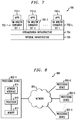
- FIG. 1 shows an information processing system configured for dynamic digital information retrieval in an illustrative embodiment of the invention.
- FIG. 2 shows a workflow for implementing an object detection model in an illustrative embodiment.
- FIG. 3 shows a flow diagram of a process for detecting one or more server components using a convolutional neural network (CNN) in an illustrative embodiment.
- CNN convolutional neural network
- FIG. 4 shows a flow diagram of a process for displaying an object specification in connection with an object detection in an illustrative embodiment.
- FIG. 5 shows an example of object detection after model analysis in an illustrative embodiment.
- FIG. 6 is a flow diagram of a process for dynamic digital information retrieval in an illustrative embodiment.
- FIGS. 7 and 8 show examples of processing platforms that may be utilized to implement at least a portion of an information processing system in illustrative embodiments.
- FIG. 1 Illustrative embodiments of the present invention will be described herein with reference to exemplary computer networks and associated computers, servers, network devices or other types of processing devices. It is to be appreciated, however, that the invention is not restricted to use with the particular illustrative network and device configurations shown. Accordingly, the term “computer network” as used herein is intended to be broadly construed, so as to encompass, for example, any system comprising multiple networked processing devices.
- FIG. 1 shows a computer network (also referred to herein as an information processing system) 100 configured in accordance with an illustrative embodiment of the invention.
- the computer network 100 comprises a plurality of user devices 102 - 1 , 102 - 2 , . . . 102 -K, collectively referred to herein as user devices 102 .
- the user devices 102 are coupled to a network 104 , where the network 104 in this embodiment is assumed to represent a sub-network or other related portion of the larger computer network 100 . Accordingly, elements 100 and 104 are both referred to herein as examples of “networks” but the latter is assumed to be a component of the former in the context of the FIG. 1 embodiment.
- Also coupled to the network 104 is a dynamic digital information retrieval system 105 .
- the user devices 102 may comprise, for example, mobile telephones, laptop computers, tablet computers, desktop computers or other types of computing devices. Such devices are examples of what are more generally referred to herein as “processing devices.” Some of these processing devices are also generally referred to herein as “computers.”
- the network 104 is assumed to comprise a portion of a global computer network such as the Internet, although other types of networks can be part of the computer network 100 , including a wide area network (WAN), a local area network (LAN), a satellite network, a telephone or cable network, a cellular network, a wireless network such as a Wi-Fi or WiMAX network, or various portions or combinations of these and other types of networks.
- the computer network 100 in some embodiments therefore comprises combinations of multiple different types of networks, each comprising processing devices configured to communicate using internet protocol (IP) or other related communication protocols.
- IP internet protocol
- the dynamic digital information retrieval system 105 has an associated database 106 configured to store server component data 107 , which illustratively comprise information pertaining to multiple server components across multiple server models.
- the database 106 in the present embodiment is implemented using one or more storage systems associated with the dynamic digital information retrieval system 105 .
- Such storage systems can comprise any of a variety of different types of storage including network-attached storage (NAS), storage area networks (SANs), direct-attached storage (DAS) and distributed DAS, as well as combinations of these and other storage types, including software-defined storage.
- NAS network-attached storage
- SANs storage area networks
- DAS direct-attached storage
- distributed DAS distributed DAS
- input-output devices 108 are also associated with the dynamic digital information retrieval system 105 , which illustratively comprise keyboards, displays or other types of input-output devices in any combination. Such input-output devices are used to support one or more user interfaces to the dynamic digital information retrieval system 105 , as well as to support communication between the dynamic digital information retrieval system 105 and other related systems and devices not explicitly shown.
- the dynamic digital information retrieval system 105 in the FIG. 1 embodiment is assumed to be implemented using at least one processing device.
- Each such processing device generally comprises at least one processor and an associated memory, and implements one or more functional modules for controlling certain features of the dynamic digital information retrieval system 105 .
- the dynamic digital information retrieval system 105 in this embodiment comprises a processor 120 coupled to a memory 122 and a network interface 124 .
- the processor 120 illustratively comprises a microprocessor, a microcontroller, an application-specific integrated circuit (ASIC), a field-programmable gate array (FPGA) or other type of processing circuitry, as well as portions or combinations of such circuitry elements.
- ASIC application-specific integrated circuit
- FPGA field-programmable gate array
- the memory 122 illustratively comprises random access memory (RAM), read-only memory (ROM) or other types of memory, in any combination.
- RAM random access memory
- ROM read-only memory
- the memory 122 and other memories disclosed herein may be viewed as examples of what are more generally referred to as “processor-readable storage media” storing executable computer program code or other types of software programs.
- One or more embodiments of the invention include articles of manufacture, such as computer-readable storage media.
- articles of manufacture include, without limitation, a storage device such as a storage disk, a storage array or an integrated circuit containing memory, as well as a wide variety of other types of computer program products.
- the term “article of manufacture” as used herein should be understood to exclude transitory, propagating signals.
- the network interface 124 allows the dynamic digital information retrieval system 105 to communicate over the network 104 with the user devices 102 , and illustratively comprises one or more conventional transceivers.
- the processor 120 further comprises a machine learning object detection model 130 , a server device type identifier 132 , a server component identifier 134 and a server device data source analyzer 136 .
- modules 130 , 132 , 134 and 136 illustrated in the processor 120 of the FIG. 1 embodiment is presented by way of example only, and alternative arrangements can be used in other embodiments.
- the functionality associated with the modules 130 , 132 , 134 and 136 in other embodiments can be combined into a single module, or separated across a larger number of modules.
- multiple distinct processors can be used to implement different ones of the modules 130 , 132 , 134 and 136 or portions thereof.
- server device type identifier 132 may be implemented at least in part in the form of software that is stored in memory 122 and executed by processor 120 .
- server component identifier 134 may be implemented at least in part in the form of software that is stored in memory 122 and executed by processor 120 .
- FIG. 1 For dynamic digital information retrieval involving user devices 102 of computer network 100 is presented by way of illustrative example only, and in other embodiments additional or alternative elements may be used. Thus, another embodiment may include additional or alternative systems, devices and other network entities, as well as different arrangements of modules and other components.
- the dynamic digital information retrieval system 105 can be eliminated and associated elements such as machine learning object detection model 130 , server device type identifier 132 , server component identifier 134 and server device data source analyzer 136 can be implemented elsewhere in the computer network 100 .
- At least one embodiment of the invention includes dynamically identifying server components from video and/or image input (live and/or static video or image input) and displaying the identified components and related information (such as from a manual, for example) through an interface.
- Such an embodiment can be implemented via a software application of a mobile device. Additionally, such a software application can utilize the camera interface of a mobile device to capture the input(s), and artificial intelligence (AI) to dynamically detect server hardware types and various components thereof.
- AI artificial intelligence
- the software application can dynamically identify (based on the captured video and/or image data) the server type as well as identify and classify one or more components of the server, along with digital information (derived, for example, from a relevant manual) related to the server type and/or identified components.
- a user can walk through multiple server components via the software application using the camera interface of the user's mobile device, and dynamically receive details pertaining to the captured components on the mobile device screen.
- identification of server type and server components is achieved through implementation of a CNN, such as, for example, a faster region-based CNN (Faster R-CNN) algorithm.
- a CNN such as, for example, a faster region-based CNN (Faster R-CNN) algorithm.
- a faster region-based CNN Faster R-CNN
- implementing a training model takes more time, as compared to a Faster R-CNN, because of higher iterations in finalizing the region of interest.
- a convolutional neural network algorithm can be run over the input image for purposes of identifying a region proposed network, as further detailed herein.
- a Faster R-CNN algorithm is implemented to perform feature extraction over an image or video input, wherein such features can include component color, component scaling, component rotation/orientation, component illumination, component edge detail, etc. Based on the feature extraction, the Faster R-CNN algorithm can determine and/or suggest one or more regions and/or components contained within the image or video input.
- FIG. 2 shows a workflow for implementing an object detection model 202 in an illustrative embodiment.
- FIG. 2 depicts the object detection model 202 , which processes an input image 204 using one or more anchor boxes 206 .
- Output from this analysis by the anchor boxes 206 in addition to input from a CNN 208 (which can be pre-trained on image classification tasks), is provided to a region proposal network 210 .
- Such inputs can serve to fine-tune the region proposal network 210 for a region proposal task (with respect to the input image 204 ), wherein this region proposal task is initialized by the input from the pre-trained CNN 208 .
- the region proposal network 210 ultimately generates and outputs a proposed region 212 .
- a non-maximum suppression (NMS) algorithm 214 is applied to the proposed region, and the output of this algorithm (that is, identification of the image with maximum image or object coverage from the proposed region(s)) is provided as input (along with input from the CNN 208 ) to a spatial pooling algorithm 216 .
- the output of the spatial pooling algorithm (that is, recognition of an object despite substantial spatial distortions (such as rotation, different angle, size, etc.), making object recognition more robust) is then provided to a regression algorithm 218 and a classifier algorithm 220 , resulting in an identification of one or more server components (from the input image 204 ).
- the regression algorithm 218 helps in extracting the closer coordinates of the identified object, while the classifier/classification algorithm 220 classifies the object in the region(s) that has been processed thus far.
- FIG. 3 shows a flow diagram of a process for detecting one or more server components using a CNN in an illustrative embodiment.
- FIG. 3 depicts an input image 302 , which is processed by CNN 304 .
- processes being carried out by the CNN 304 can include positioning an n ⁇ n spatial/sliding window over one or more convolutional feature maps 306 of the entire input image 302 .
- the CNN algorithm generates convolutional feature maps by scanning the entire input image. In this scanning process, the CNN algorithm searches for specific image properties such as curves, circles, edges, etc., and these image properties can correspond to a high probability of locating the object in the input image.
- each anchor box 308 represents a combination of a sliding window center, a scale, and a ratio, which constitute a particular shape.
- three scales and three ratios can lead to nine anchor boxes at each sliding position.
- utilization of the anchor boxes 308 can, for example, improve handling of the same object with different sizes and aspect ratios.
- the output generated by the feature maps 306 is used by a regional proposal network 310 , which determines one or more regions from the input image 302 , and provides such proposed regions to a region of interest (ROI) pooling algorithm 312 (which also receives input from the feature maps 306 ).
- ROI region of interest
- the output from the ROI pooling algorithm 312 (that is, collation of the exact location of an object from the proposed region(s)) is provided to a classifier algorithm 314 and a regressor algorithm 316 , which generate a determination of one or more identified objects 318 from the input image 302 .
- one or more embodiments of the invention can also include determining and displaying a confidence value (such as a percentage value between zero and 100) attributed to the identification of each object in output 318 .
- a Faster R-CNN object detection model (such as CNN 304 in FIG. 3 ) can be trained using proposals generated by a regional proposal network (such as network 310 in FIG. 3 ). Subsequently, such an embodiment can include using the trained Faster R-CNN model to initialize regional proposal network training. While maintaining shared convolutional layers among the object detection model and the regional proposal network, one or more embodiments of the invention can include separately fine-tuning the regional proposal network-specific layers and the unique layers of the Faster R-CNN object detection model. The fine-tuning can be carried out, for example, based on the object properties in the images (such as edges, curves, circles, etc.), and also using the corresponding anchor's aspect ratios, size, angle, etc.
- FIG. 4 shows a flow diagram of a process for displaying an object specification in connection with an object detection in an illustrative embodiment.
- Step 400 includes starting/opening the mobile object detection software application on a user's mobile device.
- Step 402 includes opening the camera interface on the mobile device and capturing an image or video input of server hardware and/or a server device.
- Step 404 includes scanning the captured input to attempt to determine a server type using a pre-trained CNN model, and step 406 includes determining whether a server type can be identified. If no (that is, no server type can be identified), then the process ends via step 414 . If yes (that is, a server type can be identified), then the process continues to step 408 , which includes scanning the captured input to attempt to identify one or more objects (such as server components) using the pre-trained CNN model.
- step 408 includes scanning the captured input to attempt to identify one or more objects (such as server components) using the pre-trained CNN model.
- Step 410 includes determining whether one or more objects can be identified. If no (that is, no objects can be identified in the image or video input), then the process returns to step 408 . If yes (that is, one or more objects are identified in the input), then the process continues to step 412 , which includes retrieving and displaying (via the interface of the mobile device) specification information pertaining to the identified object(s). The process subsequently ends at step 414 .
- FIG. 5 shows an example of object detection after model analysis in an illustrative embodiment.
- FIG. 5 depicts a variety of images of individual server components 502 , which are compared to a pre-trained model 504 of objects for purposes of identification.
- identification of server components 506 can include components such as a system identification button, a power-on indicator, a non-maskable interrupt (NMI) button, an optical drive, a vFlash media card slot, universal serial bus (USB) connectors, a video connector, liquid-crystal display (LCD) menu buttons, an LCD panel, an information tag, a tape drive slot, one or more hard drives, etc.
- a system identification button such as a system identification button, a power-on indicator, a non-maskable interrupt (NMI) button, an optical drive, a vFlash media card slot, universal serial bus (USB) connectors, a video connector, liquid-crystal display (LCD) menu buttons, an LCD panel, an information tag, a
- FIG. 6 is a flow diagram of a process for dynamically detecting server components and displaying data source specification corresponding thereto in an illustrative embodiment. It is to be understood that this particular process is only an example, and additional or alternative processes can be carried out in other embodiments.
- the process includes steps 600 through 606 . These steps are assumed to be performed by the processor 120 utilizing its modules 130 , 132 , 134 and 136 .
- Step 600 includes training a machine learning object detection model using multiple server component images and one or more features of the multiple server component images.
- the machine learning object detection model can include a region-based convolutional neural network model (such as, for example, a faster-CNN model).
- the one or more features of the multiple server component images can include component color, component scale, component orientation, component edge detail, and/or component illumination.
- Step 602 includes determining a type of server device captured by at least one camera-derived input, wherein determining the type of server device comprises analyzing the at least one camera-derived input using the machine learning object detection model.
- the at least one camera-derived input can include a live video input, a stored video input, a new image input, and/or a stored image input.
- Step 604 includes identifying one or more server components captured by the at least one camera-derived input by analyzing, within a context of the determined type of server device, the at least one camera-derived input using the machine learning object detection model.
- the one or more server components can include at least one of a port, a slot, a switch, a power indicator, an information tag, a drive, a panel, a disk, and a connector.
- identifying the one or more server components can include performing, via the machine learning object detection model, feature extraction over the at least one camera-derived input. Performing the feature extraction can include extracting, from the at least one camera-derived input, one or more component features comprising component color, component scale, component orientation, component edge detail, and/or component illumination.
- identifying the one or more server components can also include determining, based at least in part on the feature extraction, one or more regions of the determined type of server device captured by the at least one camera-derived input.
- Step 606 includes outputting, to at least one display, information pertaining to the one or more identified server components, wherein the information is retrieved from at least a portion of a data source related to the determined type of server device.
- Outputting the information pertaining to the one or more identified server components can include displaying the information via an interface of a mobile device, wherein the mobile device captured the at least one camera-derived input.
- step 600 , step 602 , step 604 and step 606 can be performed by a software application executing on at least one processing device, wherein the at least one processing device comprises a mobile device.
- processing operations and other network functionality described in conjunction with the flow diagram of FIG. 6 are presented by way of illustrative example only, and should not be construed as limiting the scope of the invention in any way.
- Alternative embodiments can use other types of processing operations to detect session-based access anomalies and undertake appropriate remediation actions.
- the ordering of the process steps may be varied in other embodiments, or certain steps may be performed concurrently with one another rather than serially.
- the process steps or subsets thereof may be repeated periodically in conjunction with respective distinct instances of session-based anomaly detection for different user identifiers.
- some embodiments are configured to provide efficiencies and environmental benefits by precluding the need to print and ship large numbers of physical documents. Additionally, these and other embodiments can enable dynamic component look-up capabilities, precluding the need for time-consuming searching and side-by-side comparisons.
- a given such processing platform comprises at least one processing device comprising a processor coupled to a memory.
- the processor and memory in some embodiments comprise respective processor and memory elements of a virtual machine or container provided using one or more underlying physical machines.
- the term “processing device” as used herein is intended to be broadly construed so as to encompass a wide variety of different arrangements of physical processors, memories and other device components as well as virtual instances of such components.
- a “processing device” in some embodiments can comprise or be executed across one or more virtual processors. Processing devices can therefore be physical or virtual and can be executed across one or more physical or virtual processors. It should also be noted that a given virtual device can be mapped to a portion of a physical one.
- the cloud infrastructure further comprises sets of applications running on respective ones of the virtual machines under the control of the hypervisor. It is also possible to use multiple hypervisors each providing a set of virtual machines using at least one underlying physical machine. Different sets of virtual machines provided by one or more hypervisors may be utilized in configuring multiple instances of various components of the system.
- cloud infrastructure can be used to provide what is also referred to herein as a multi-tenant environment.
- One or more system components, or portions thereof, are illustratively implemented for use by tenants of such a multi-tenant environment.
- cloud infrastructure as disclosed herein can include cloud-based systems such as AWS, GCP and Microsoft Azure.
- Virtual machines provided in such systems can be used to implement at least portions of one or more of a computer system and a content addressable storage system in illustrative embodiments.
- object stores such as Amazon S3, GCP Cloud Storage, and Microsoft Azure Blob Storage.
- the cloud infrastructure additionally or alternatively comprises a plurality of containers implemented using container host devices.
- a given container of cloud infrastructure illustratively comprises a Docker container or other type of Linux Container (LXC).
- LXC Linux Container
- the containers may run on virtual machines in a multi-tenant environment, although other arrangements are possible.
- the containers may be utilized to implement a variety of different types of functionality within the system 100 .
- containers can be used to implement respective processing devices providing compute and/or storage services of a cloud-based system.
- containers may be used in combination with other virtualization infrastructure such as virtual machines implemented using a hypervisor.
- processing platforms will now be described in greater detail with reference to FIGS. 7 and 8 . Although described in the context of system 100 , these platforms may also be used to implement at least portions of other information processing systems in other embodiments.
- FIG. 7 shows an example processing platform comprising cloud infrastructure 700 .
- the cloud infrastructure 700 comprises a combination of physical and virtual processing resources that may be utilized to implement at least a portion of the information processing system 100 .
- the cloud infrastructure 700 comprises multiple virtual machines (VMs) and/or container sets 702 - 1 , 702 - 2 , . . . 702 -L implemented using virtualization infrastructure 704 .
- the virtualization infrastructure 704 runs on physical infrastructure 705 , and illustratively comprises one or more hypervisors and/or operating system level virtualization infrastructure.
- the operating system level virtualization infrastructure illustratively comprises kernel control groups of a Linux operating system or other type of operating system.
- the cloud infrastructure 700 further comprises sets of applications 710 - 1 , 710 - 2 , . . . 710 -L running on respective ones of the VMs/container sets 702 - 1 , 702 - 2 , . . . 702 -L under the control of the virtualization infrastructure 704 .
- the VMs/container sets 702 may comprise respective VMs, respective sets of one or more containers, or respective sets of one or more containers running in VMs.
- the VMs/container sets 702 comprise respective VMs implemented using virtualization infrastructure 704 that comprises at least one hypervisor.
- Such implementations can provide deduplication estimate generation functionality of the type described above for one or more processes running on a given one of the VMs.
- each of the VMs can implement deduplication control logic and associated deduplication estimate tables for providing deduplication estimate generation functionality for one or more processes running on that particular VM.
- hypervisor platform that may be used to implement a hypervisor within the virtualization infrastructure 704 is the VMware® vSphere® which may have an associated virtual infrastructure management system such as the VMware® vCenterTM.
- the underlying physical machines may comprise one or more distributed processing platforms that include one or more storage systems.
- the VMs/container sets 702 comprise respective containers implemented using virtualization infrastructure 704 that provides operating system level virtualization functionality, such as support for Docker containers running on bare metal hosts, or Docker containers running on VMs.
- the containers are illustratively implemented using respective kernel control groups of the operating system.
- Such implementations can provide deduplication estimate generation functionality of the type described above for one or more processes running on different ones of the containers.
- a container host device supporting multiple containers of one or more container sets can implement one or more instances of deduplication control logic and associated deduplication estimate tables for use in generating deduplication estimates.
- one or more of the processing modules or other components of system 100 may each run on a computer, server, storage device or other processing platform element.
- a given such element may be viewed as an example of what is more generally referred to herein as a “processing device.”
- the cloud infrastructure 700 shown in FIG. 7 may represent at least a portion of one processing platform.
- processing platform 800 shown in FIG. 8 is another example of such a processing platform.
- the processing platform 800 in this embodiment comprises a portion of system 100 and includes a plurality of processing devices, denoted 802 - 1 , 802 - 2 , 802 - 3 , . . . 802 -K, which communicate with one another over a network 804 .
- the network 804 may comprise any type of network, including by way of example a global computer network such as the Internet, a WAN, a LAN, a satellite network, a telephone or cable network, a cellular network, a wireless network such as a Wi-Fi or WiMAX network, or various portions or combinations of these and other types of networks.
- the processing device 802 - 1 in the processing platform 800 comprises a processor 810 coupled to a memory 812 .
- the processor 810 may comprise a microprocessor, a microcontroller, an application-specific integrated circuit (ASIC), a field-programmable gate array (FPGA) or other type of processing circuitry, as well as portions or combinations of such circuitry elements.
- ASIC application-specific integrated circuit
- FPGA field-programmable gate array
- the memory 812 may comprise random access memory (RAM), read-only memory (ROM) or other types of memory, in any combination.
- RAM random access memory
- ROM read-only memory
- the memory 812 and other memories disclosed herein should be viewed as illustrative examples of what are more generally referred to as “processor-readable storage media” storing executable program code of one or more software programs.
- Articles of manufacture comprising such processor-readable storage media are considered illustrative embodiments.
- a given such article of manufacture may comprise, for example, a storage array, a storage disk or an integrated circuit containing RAM, ROM or other electronic memory, or any of a wide variety of other types of computer program products.
- the term “article of manufacture” as used herein should be understood to exclude transitory, propagating signals. Numerous other types of computer program products comprising processor-readable storage media can be used.
- network interface circuitry 814 is included in the processing device 802 - 1 , which is used to interface the processing device with the network 804 and other system components, and may comprise conventional transceivers.
- the other processing devices 802 of the processing platform 800 are assumed to be configured in a manner similar to that shown for processing device 802 - 1 in the figure.
- processing platform 800 shown in the figure is presented by way of example only, and system 100 may include additional or alternative processing platforms, as well as numerous distinct processing platforms in any combination, with each such platform comprising one or more computers, servers, storage devices or other processing devices.
- processing platforms used to implement illustrative embodiments can comprise different types of virtualization infrastructure, in place of or in addition to virtualization infrastructure comprising virtual machines.
- virtualization infrastructure illustratively includes container-based virtualization infrastructure configured to provide Docker containers or other types of LXCs.
- portions of a given processing platform in some embodiments can comprise converged infrastructure such as VxRailTM, VxRackTM, VxBlockTM, or Vblock® converged infrastructure commercially available from VCE, the Virtual Computing Environment Company, now the Converged Platform and Solutions Division of Dell EMC.
- VxRailTM, VxRackTM, VxBlockTM, or Vblock® converged infrastructure commercially available from VCE, the Virtual Computing Environment Company, now the Converged Platform and Solutions Division of Dell EMC.
- particular types of storage products that can be used in implementing a given storage system of a distributed processing system in an illustrative embodiment include VNX® and Symmetrix VMAX® storage arrays, software-defined storage products such as ScaleIOTM and ViPR®, all-flash and hybrid flash storage arrays such as UnityTM, cloud storage products such as Elastic Cloud Storage (ECS), object-based storage products such as Atmos®, scale-out all-flash storage arrays such as XtremIOTM, and scale-out NAS clusters comprising Isilon® platform nodes and associated accelerators, all from Dell EMC. Combinations of multiple ones of these and other storage products can also be used in implementing a given storage system in an illustrative embodiment.
Abstract
Description
Claims (20)
Priority Applications (1)
| Application Number | Priority Date | Filing Date | Title |
|---|---|---|---|
| US16/033,804 US11100367B2 (en) | 2018-07-12 | 2018-07-12 | Dynamic digital information retrieval implemented via artificial intelligence |
Applications Claiming Priority (1)
| Application Number | Priority Date | Filing Date | Title |
|---|---|---|---|
| US16/033,804 US11100367B2 (en) | 2018-07-12 | 2018-07-12 | Dynamic digital information retrieval implemented via artificial intelligence |
Publications (2)
| Publication Number | Publication Date |
|---|---|
| US20200019819A1 US20200019819A1 (en) | 2020-01-16 |
| US11100367B2 true US11100367B2 (en) | 2021-08-24 |
Family
ID=69138361
Family Applications (1)
| Application Number | Title | Priority Date | Filing Date |
|---|---|---|---|
| US16/033,804 Active 2038-12-28 US11100367B2 (en) | 2018-07-12 | 2018-07-12 | Dynamic digital information retrieval implemented via artificial intelligence |
Country Status (1)
| Country | Link |
|---|---|
| US (1) | US11100367B2 (en) |
Families Citing this family (1)
| Publication number | Priority date | Publication date | Assignee | Title |
|---|---|---|---|---|
| JP7365647B2 (en) | 2019-03-29 | 2023-10-20 | パナソニックIpマネジメント株式会社 | angular velocity sensor |
Citations (17)
| Publication number | Priority date | Publication date | Assignee | Title |
|---|---|---|---|---|
| US20110268369A1 (en) * | 2010-05-03 | 2011-11-03 | Microsoft Corporation | Generating a combined image from multiple images |
| US20130124518A1 (en) | 2011-11-14 | 2013-05-16 | Sony Corporation | Information registration device, information registration method, information registration system, information presentation device, informaton presentation method, informaton presentaton system, and program |
| US20150125042A1 (en) * | 2013-10-08 | 2015-05-07 | Smartlanes Technologies, Llc | Method and system for data collection using processed image data |
| US9317753B2 (en) | 2008-03-03 | 2016-04-19 | Avigilon Patent Holding 2 Corporation | Method of searching data to identify images of an object captured by a camera system |
| US9424493B2 (en) * | 2014-10-09 | 2016-08-23 | Microsoft Technology Licensing, Llc | Generic object detection in images |
| US20170352143A1 (en) * | 2016-06-03 | 2017-12-07 | Conduent Business Services, Llc | System and method for assessing usability of captured images |
| US20180150791A1 (en) * | 2016-11-29 | 2018-05-31 | Wal-Mart Stores, Inc. | Augmented reality-assisted modular set-up and product stocking systems and methods |
| US20180157932A1 (en) * | 2016-12-05 | 2018-06-07 | Sap Se | Systems and methods for integrated cargo inspection |
| US10019654B1 (en) * | 2017-06-28 | 2018-07-10 | Accenture Global Solutions Limited | Image object recognition |
| US20180365278A1 (en) * | 2017-06-14 | 2018-12-20 | Salesforce.Com, Inc. | Automated image-based record creation and related database systems |
| US20190019052A1 (en) * | 2017-07-14 | 2019-01-17 | Adobe Systems Incorporated | Text Region Detection in Digital Images using Image Tag Filtering |
| US20190130292A1 (en) * | 2017-10-30 | 2019-05-02 | Sap Se | Dynamic self-learning system |
| US20190215424A1 (en) * | 2018-01-10 | 2019-07-11 | Trax Technologies Solutions Pte Ltd. | Camera configured to be mounted to store shelf |
| US20190279293A1 (en) * | 2018-03-08 | 2019-09-12 | Capital One Services, Llc | Image analysis and identification using machine learning with output estimation |
| US20190291277A1 (en) * | 2017-07-25 | 2019-09-26 | Mbl Limited | Systems and methods for operating a robotic system and executing robotic interactions |
| US10445569B1 (en) * | 2016-08-30 | 2019-10-15 | A9.Com, Inc. | Combination of heterogeneous recognizer for image-based character recognition |
| US20190340459A1 (en) * | 2018-05-04 | 2019-11-07 | EMC IP Holding Company LLC | Analyzing storage systems using machine learning systems |
-
2018
- 2018-07-12 US US16/033,804 patent/US11100367B2/en active Active
Patent Citations (17)
| Publication number | Priority date | Publication date | Assignee | Title |
|---|---|---|---|---|
| US9317753B2 (en) | 2008-03-03 | 2016-04-19 | Avigilon Patent Holding 2 Corporation | Method of searching data to identify images of an object captured by a camera system |
| US20110268369A1 (en) * | 2010-05-03 | 2011-11-03 | Microsoft Corporation | Generating a combined image from multiple images |
| US20130124518A1 (en) | 2011-11-14 | 2013-05-16 | Sony Corporation | Information registration device, information registration method, information registration system, information presentation device, informaton presentation method, informaton presentaton system, and program |
| US20150125042A1 (en) * | 2013-10-08 | 2015-05-07 | Smartlanes Technologies, Llc | Method and system for data collection using processed image data |
| US9424493B2 (en) * | 2014-10-09 | 2016-08-23 | Microsoft Technology Licensing, Llc | Generic object detection in images |
| US20170352143A1 (en) * | 2016-06-03 | 2017-12-07 | Conduent Business Services, Llc | System and method for assessing usability of captured images |
| US10445569B1 (en) * | 2016-08-30 | 2019-10-15 | A9.Com, Inc. | Combination of heterogeneous recognizer for image-based character recognition |
| US20180150791A1 (en) * | 2016-11-29 | 2018-05-31 | Wal-Mart Stores, Inc. | Augmented reality-assisted modular set-up and product stocking systems and methods |
| US20180157932A1 (en) * | 2016-12-05 | 2018-06-07 | Sap Se | Systems and methods for integrated cargo inspection |
| US20180365278A1 (en) * | 2017-06-14 | 2018-12-20 | Salesforce.Com, Inc. | Automated image-based record creation and related database systems |
| US10019654B1 (en) * | 2017-06-28 | 2018-07-10 | Accenture Global Solutions Limited | Image object recognition |
| US20190019052A1 (en) * | 2017-07-14 | 2019-01-17 | Adobe Systems Incorporated | Text Region Detection in Digital Images using Image Tag Filtering |
| US20190291277A1 (en) * | 2017-07-25 | 2019-09-26 | Mbl Limited | Systems and methods for operating a robotic system and executing robotic interactions |
| US20190130292A1 (en) * | 2017-10-30 | 2019-05-02 | Sap Se | Dynamic self-learning system |
| US20190215424A1 (en) * | 2018-01-10 | 2019-07-11 | Trax Technologies Solutions Pte Ltd. | Camera configured to be mounted to store shelf |
| US20190279293A1 (en) * | 2018-03-08 | 2019-09-12 | Capital One Services, Llc | Image analysis and identification using machine learning with output estimation |
| US20190340459A1 (en) * | 2018-05-04 | 2019-11-07 | EMC IP Holding Company LLC | Analyzing storage systems using machine learning systems |
Also Published As
| Publication number | Publication date |
|---|---|
| US20200019819A1 (en) | 2020-01-16 |
Similar Documents
| Publication | Publication Date | Title |
|---|---|---|
| US10860836B1 (en) | Generation of synthetic image data for computer vision models | |
| US10043255B1 (en) | Utilizing a machine learning model to automatically visually validate a user interface for multiple platforms | |
| US10229499B2 (en) | Skin lesion segmentation using deep convolution networks guided by local unsupervised learning | |
| US10936911B2 (en) | Logo detection | |
| US9922265B2 (en) | Global-scale object detection using satellite imagery | |
| US11321822B2 (en) | Determining image defects using image comparisons | |
| US11631260B1 (en) | Generation of synthetic image data using three-dimensional models | |
| US11494893B2 (en) | Systems and methods for managing physical connections of a connector panel | |
| EP4040311A1 (en) | Utilizing machine learning and natural language processing to extract and verify vaccination data | |
| US10866985B2 (en) | Image-based search and recommendation techniques implemented via artificial intelligence | |
| US20200184215A1 (en) | Photographic results by composition analysis using deep learning neural networks | |
| US11429813B1 (en) | Automated model selection for network-based image recognition service | |
| US11244466B2 (en) | Automated capacity management using artificial intelligence techniques | |
| US20220277574A1 (en) | Image classification using color profiles | |
| US20170236035A1 (en) | System, apparatus and method for configuration of industrial vision control modules | |
| US11100367B2 (en) | Dynamic digital information retrieval implemented via artificial intelligence | |
| US20210406568A1 (en) | Utilizing multiple stacked machine learning models to detect deepfake content | |
| US20210240368A1 (en) | Automatically Determining Sizing Configurations for Storage Components Using Machine Learning Techniques | |
| US10685292B1 (en) | Similarity-based retrieval of software investigation log sets for accelerated software deployment | |
| US11216911B2 (en) | Device manufacturing cycle time reduction using machine learning techniques | |
| US20240119732A1 (en) | Operation Management System Utilizing a Wearable Device | |
| US20230062313A1 (en) | Generating 2d mapping using 3d data | |
| US20220207388A1 (en) | Automatically generating conditional instructions for resolving predicted system issues using machine learning techniques | |
| US20220036159A1 (en) | System, method and network node for generating at least one classification based on machine learning techniques | |
| US20240144712A1 (en) | Localized anomaly detection in digital documents using machine learning techniques |
Legal Events
| Date | Code | Title | Description |
|---|---|---|---|
| AS | Assignment |
Owner name: EMC IP HOLDING COMPANY LLC, MASSACHUSETTS Free format text: ASSIGNMENT OF ASSIGNORS INTEREST;ASSIGNORS:KOUSHIK BANGALORE SURYANARAYANA, BHARATH;SN, FAIZAL;PONNUSAMY, SATHISH KUMAR;REEL/FRAME:046335/0088 Effective date: 20180712 |
|
| FEPP | Fee payment procedure |
Free format text: ENTITY STATUS SET TO UNDISCOUNTED (ORIGINAL EVENT CODE: BIG.); ENTITY STATUS OF PATENT OWNER: LARGE ENTITY |
|
| AS | Assignment |
Owner name: CREDIT SUISSE AG, CAYMAN ISLANDS BRANCH, AS COLLAT Free format text: PATENT SECURITY AGREEMENT (CREDIT);ASSIGNORS:DELL PRODUCTS L.P.;EMC CORPORATION;EMC IP HOLDING COMPANY LLC;REEL/FRAME:047648/0346 Effective date: 20180906 Owner name: THE BANK OF NEW YORK MELLON TRUST COMPANY, N.A., A Free format text: PATENT SECURITY AGREEMENT (NOTES);ASSIGNORS:DELL PRODUCTS L.P.;EMC CORPORATION;EMC IP HOLDING COMPANY LLC;REEL/FRAME:047648/0422 Effective date: 20180906 Owner name: CREDIT SUISSE AG, CAYMAN ISLANDS BRANCH, AS COLLATERAL AGENT, NORTH CAROLINA Free format text: PATENT SECURITY AGREEMENT (CREDIT);ASSIGNORS:DELL PRODUCTS L.P.;EMC CORPORATION;EMC IP HOLDING COMPANY LLC;REEL/FRAME:047648/0346 Effective date: 20180906 Owner name: THE BANK OF NEW YORK MELLON TRUST COMPANY, N.A., AS COLLATERAL AGENT, TEXAS Free format text: PATENT SECURITY AGREEMENT (NOTES);ASSIGNORS:DELL PRODUCTS L.P.;EMC CORPORATION;EMC IP HOLDING COMPANY LLC;REEL/FRAME:047648/0422 Effective date: 20180906 |
|
| AS | Assignment |
Owner name: THE BANK OF NEW YORK MELLON TRUST COMPANY, N.A., T Free format text: SECURITY AGREEMENT;ASSIGNORS:CREDANT TECHNOLOGIES, INC.;DELL INTERNATIONAL L.L.C.;DELL MARKETING L.P.;AND OTHERS;REEL/FRAME:049452/0223 Effective date: 20190320 Owner name: THE BANK OF NEW YORK MELLON TRUST COMPANY, N.A., TEXAS Free format text: SECURITY AGREEMENT;ASSIGNORS:CREDANT TECHNOLOGIES, INC.;DELL INTERNATIONAL L.L.C.;DELL MARKETING L.P.;AND OTHERS;REEL/FRAME:049452/0223 Effective date: 20190320 |
|
| STPP | Information on status: patent application and granting procedure in general |
Free format text: NON FINAL ACTION MAILED |
|
| STPP | Information on status: patent application and granting procedure in general |
Free format text: RESPONSE TO NON-FINAL OFFICE ACTION ENTERED AND FORWARDED TO EXAMINER |
|
| AS | Assignment |
Owner name: THE BANK OF NEW YORK MELLON TRUST COMPANY, N.A., TEXAS Free format text: SECURITY AGREEMENT;ASSIGNORS:CREDANT TECHNOLOGIES INC.;DELL INTERNATIONAL L.L.C.;DELL MARKETING L.P.;AND OTHERS;REEL/FRAME:053546/0001 Effective date: 20200409 |
|
| STPP | Information on status: patent application and granting procedure in general |
Free format text: FINAL REJECTION MAILED |
|
| STPP | Information on status: patent application and granting procedure in general |
Free format text: RESPONSE AFTER FINAL ACTION FORWARDED TO EXAMINER |
|
| STPP | Information on status: patent application and granting procedure in general |
Free format text: DOCKETED NEW CASE - READY FOR EXAMINATION |
|
| STPP | Information on status: patent application and granting procedure in general |
Free format text: NON FINAL ACTION MAILED |
|
| STPP | Information on status: patent application and granting procedure in general |
Free format text: RESPONSE TO NON-FINAL OFFICE ACTION ENTERED AND FORWARDED TO EXAMINER |
|
| STPP | Information on status: patent application and granting procedure in general |
Free format text: NOTICE OF ALLOWANCE MAILED -- APPLICATION RECEIVED IN OFFICE OF PUBLICATIONS |
|
| STPP | Information on status: patent application and granting procedure in general |
Free format text: PUBLICATIONS -- ISSUE FEE PAYMENT RECEIVED |
|
| STPP | Information on status: patent application and granting procedure in general |
Free format text: PUBLICATIONS -- ISSUE FEE PAYMENT VERIFIED |
|
| STCF | Information on status: patent grant |
Free format text: PATENTED CASE |
|
| AS | Assignment |
Owner name: EMC IP HOLDING COMPANY LLC, TEXAS Free format text: RELEASE OF SECURITY INTEREST AT REEL 047648 FRAME 0346;ASSIGNOR:CREDIT SUISSE AG, CAYMAN ISLANDS BRANCH;REEL/FRAME:058298/0510 Effective date: 20211101 Owner name: EMC CORPORATION, MASSACHUSETTS Free format text: RELEASE OF SECURITY INTEREST AT REEL 047648 FRAME 0346;ASSIGNOR:CREDIT SUISSE AG, CAYMAN ISLANDS BRANCH;REEL/FRAME:058298/0510 Effective date: 20211101 Owner name: DELL PRODUCTS L.P., TEXAS Free format text: RELEASE OF SECURITY INTEREST AT REEL 047648 FRAME 0346;ASSIGNOR:CREDIT SUISSE AG, CAYMAN ISLANDS BRANCH;REEL/FRAME:058298/0510 Effective date: 20211101 |
|
| AS | Assignment |
Owner name: EMC IP HOLDING COMPANY LLC, TEXAS Free format text: RELEASE OF SECURITY INTEREST IN PATENTS PREVIOUSLY RECORDED AT REEL/FRAME (047648/0422);ASSIGNOR:THE BANK OF NEW YORK MELLON TRUST COMPANY, N.A., AS NOTES COLLATERAL AGENT;REEL/FRAME:060160/0862 Effective date: 20220329 Owner name: EMC CORPORATION, MASSACHUSETTS Free format text: RELEASE OF SECURITY INTEREST IN PATENTS PREVIOUSLY RECORDED AT REEL/FRAME (047648/0422);ASSIGNOR:THE BANK OF NEW YORK MELLON TRUST COMPANY, N.A., AS NOTES COLLATERAL AGENT;REEL/FRAME:060160/0862 Effective date: 20220329 Owner name: DELL PRODUCTS L.P., TEXAS Free format text: RELEASE OF SECURITY INTEREST IN PATENTS PREVIOUSLY RECORDED AT REEL/FRAME (047648/0422);ASSIGNOR:THE BANK OF NEW YORK MELLON TRUST COMPANY, N.A., AS NOTES COLLATERAL AGENT;REEL/FRAME:060160/0862 Effective date: 20220329 |