US11099158B2 - Three dimensional detection device, surface detection method and production line apparatus using the same - Google Patents
Three dimensional detection device, surface detection method and production line apparatus using the same Download PDFInfo
- Publication number
- US11099158B2 US11099158B2 US16/800,620 US202016800620A US11099158B2 US 11099158 B2 US11099158 B2 US 11099158B2 US 202016800620 A US202016800620 A US 202016800620A US 11099158 B2 US11099158 B2 US 11099158B2
- Authority
- US
- United States
- Prior art keywords
- image
- ultrasonic
- detection
- tested object
- detection device
- Prior art date
- Legal status (The legal status is an assumption and is not a legal conclusion. Google has not performed a legal analysis and makes no representation as to the accuracy of the status listed.)
- Active
Links
Images


Classifications
-
- G—PHYSICS
- G01—MEASURING; TESTING
- G01S—RADIO DIRECTION-FINDING; RADIO NAVIGATION; DETERMINING DISTANCE OR VELOCITY BY USE OF RADIO WAVES; LOCATING OR PRESENCE-DETECTING BY USE OF THE REFLECTION OR RERADIATION OF RADIO WAVES; ANALOGOUS ARRANGEMENTS USING OTHER WAVES
- G01S7/00—Details of systems according to groups G01S13/00, G01S15/00, G01S17/00
- G01S7/52—Details of systems according to groups G01S13/00, G01S15/00, G01S17/00 of systems according to group G01S15/00
- G01S7/521—Constructional features
-
- G—PHYSICS
- G01—MEASURING; TESTING
- G01N—INVESTIGATING OR ANALYSING MATERIALS BY DETERMINING THEIR CHEMICAL OR PHYSICAL PROPERTIES
- G01N29/00—Investigating or analysing materials by the use of ultrasonic, sonic or infrasonic waves; Visualisation of the interior of objects by transmitting ultrasonic or sonic waves through the object
- G01N29/04—Analysing solids
- G01N29/045—Analysing solids by imparting shocks to the workpiece and detecting the vibrations or the acoustic waves caused by the shocks
- G01N29/046—Analysing solids by imparting shocks to the workpiece and detecting the vibrations or the acoustic waves caused by the shocks using the echo of particles imparting on a surface; using acoustic emission of particles
-
- G—PHYSICS
- G01—MEASURING; TESTING
- G01N—INVESTIGATING OR ANALYSING MATERIALS BY DETERMINING THEIR CHEMICAL OR PHYSICAL PROPERTIES
- G01N29/00—Investigating or analysing materials by the use of ultrasonic, sonic or infrasonic waves; Visualisation of the interior of objects by transmitting ultrasonic or sonic waves through the object
- G01N29/04—Analysing solids
- G01N29/06—Visualisation of the interior, e.g. acoustic microscopy
- G01N29/0654—Imaging
-
- G—PHYSICS
- G01—MEASURING; TESTING
- G01N—INVESTIGATING OR ANALYSING MATERIALS BY DETERMINING THEIR CHEMICAL OR PHYSICAL PROPERTIES
- G01N29/00—Investigating or analysing materials by the use of ultrasonic, sonic or infrasonic waves; Visualisation of the interior of objects by transmitting ultrasonic or sonic waves through the object
- G01N29/04—Analysing solids
- G01N29/07—Analysing solids by measuring propagation velocity or propagation time of acoustic waves
-
- G—PHYSICS
- G01—MEASURING; TESTING
- G01N—INVESTIGATING OR ANALYSING MATERIALS BY DETERMINING THEIR CHEMICAL OR PHYSICAL PROPERTIES
- G01N29/00—Investigating or analysing materials by the use of ultrasonic, sonic or infrasonic waves; Visualisation of the interior of objects by transmitting ultrasonic or sonic waves through the object
- G01N29/44—Processing the detected response signal, e.g. electronic circuits specially adapted therefor
- G01N29/4409—Processing the detected response signal, e.g. electronic circuits specially adapted therefor by comparison
- G01N29/4427—Processing the detected response signal, e.g. electronic circuits specially adapted therefor by comparison with stored values, e.g. threshold values
-
- G—PHYSICS
- G01—MEASURING; TESTING
- G01S—RADIO DIRECTION-FINDING; RADIO NAVIGATION; DETERMINING DISTANCE OR VELOCITY BY USE OF RADIO WAVES; LOCATING OR PRESENCE-DETECTING BY USE OF THE REFLECTION OR RERADIATION OF RADIO WAVES; ANALOGOUS ARRANGEMENTS USING OTHER WAVES
- G01S15/00—Systems using the reflection or reradiation of acoustic waves, e.g. sonar systems
- G01S15/87—Combinations of sonar systems
-
- G—PHYSICS
- G01—MEASURING; TESTING
- G01S—RADIO DIRECTION-FINDING; RADIO NAVIGATION; DETERMINING DISTANCE OR VELOCITY BY USE OF RADIO WAVES; LOCATING OR PRESENCE-DETECTING BY USE OF THE REFLECTION OR RERADIATION OF RADIO WAVES; ANALOGOUS ARRANGEMENTS USING OTHER WAVES
- G01S15/00—Systems using the reflection or reradiation of acoustic waves, e.g. sonar systems
- G01S15/88—Sonar systems specially adapted for specific applications
- G01S15/89—Sonar systems specially adapted for specific applications for mapping or imaging
-
- G—PHYSICS
- G06—COMPUTING; CALCULATING OR COUNTING
- G06T—IMAGE DATA PROCESSING OR GENERATION, IN GENERAL
- G06T7/00—Image analysis
- G06T7/0002—Inspection of images, e.g. flaw detection
- G06T7/0004—Industrial image inspection
- G06T7/001—Industrial image inspection using an image reference approach
-
- G—PHYSICS
- G01—MEASURING; TESTING
- G01N—INVESTIGATING OR ANALYSING MATERIALS BY DETERMINING THEIR CHEMICAL OR PHYSICAL PROPERTIES
- G01N2291/00—Indexing codes associated with group G01N29/00
- G01N2291/02—Indexing codes associated with the analysed material
- G01N2291/028—Material parameters
- G01N2291/0289—Internal structure, e.g. defects, grain size, texture
-
- G—PHYSICS
- G01—MEASURING; TESTING
- G01N—INVESTIGATING OR ANALYSING MATERIALS BY DETERMINING THEIR CHEMICAL OR PHYSICAL PROPERTIES
- G01N2291/00—Indexing codes associated with group G01N29/00
- G01N2291/04—Wave modes and trajectories
- G01N2291/045—External reflections, e.g. on reflectors
-
- G—PHYSICS
- G06—COMPUTING; CALCULATING OR COUNTING
- G06T—IMAGE DATA PROCESSING OR GENERATION, IN GENERAL
- G06T2207/00—Indexing scheme for image analysis or image enhancement
- G06T2207/10—Image acquisition modality
- G06T2207/10132—Ultrasound image
- G06T2207/10136—3D ultrasound image
-
- G—PHYSICS
- G06—COMPUTING; CALCULATING OR COUNTING
- G06T—IMAGE DATA PROCESSING OR GENERATION, IN GENERAL
- G06T2207/00—Indexing scheme for image analysis or image enhancement
- G06T2207/30—Subject of image; Context of image processing
- G06T2207/30108—Industrial image inspection
- G06T2207/30116—Casting
-
- G—PHYSICS
- G06—COMPUTING; CALCULATING OR COUNTING
- G06T—IMAGE DATA PROCESSING OR GENERATION, IN GENERAL
- G06T2207/00—Indexing scheme for image analysis or image enhancement
- G06T2207/30—Subject of image; Context of image processing
- G06T2207/30108—Industrial image inspection
- G06T2207/30164—Workpiece; Machine component
Definitions
- the present disclosure relates to a detection technology which utilizes ultrasonic to establish a three dimensional image, wherein the three dimensional image is directly compared with a dimension and a size of an accepted object, so as to reduce a detection time, and the present disclosure is suitable for the requirement of the application of the automatically continuous processing process.
- the surface quality detection of the product is very important.
- the surface detection can further find whether the related processing device operates abnormally or runs down according to the produced defect on the product surface.
- the conventional surface detection method for the product is usually performed by a visual inspection manner.
- the quality checker visually checks the surface statuses of the upper surface and the lower surface associated with the produce, she or he must make a related detection judgment in time, and the detection results may differ from person to person, thus not being able to reflect the whole quality statuses of the products in time due to the occasional detection loss.
- the related automatic surface detection system is provided accordingly, and the well-known scanning manner by using the optical instrument (such as, infrared ray scanner) is used to check the defect on the product surface. Since the optical scanning forms the line from the points, and forms the surface from the lines, it must cost long time, and the time interval for randomly sampling is relatively increased. Therefore, such prior art is not suitable for the current requirement of the application of the automatically continuous processing process.
- the optical instrument such as, infrared ray scanner
- the present disclosure is used to provide a three dimensional (3D) detection device, a surface detection method and a production line apparatus using the same, wherein a 3D image of a tested object is established and compared with that of an accepted object, and the present disclosure is suitable for the requirement of the application of the automatically continuous processing process.
- One objective of the present disclosure is to provide a 3D detection device which at least comprises: a detection supporter base, disposed on a transmission device of a production line apparatus; ultrasonic transceiver modules, disposed on at least one inner base surface of the detection supporter base, for emitting ultrasonic signals to surfaces of a tested object which enters the detection supporter base, receiving the reflected ultrasonic signals from the surfaces of the tested object, and generating detection signals according to the reflected ultrasonic signals; and a controller, communicatively connected to the ultrasonic transceiver modules, for receiving the detection signals, generating a 3D ultrasonic image according to the detection signals, and comparing the 3D ultrasonic image with a pre-established 3D image, so as to determine whether the surfaces of the tested object have at least one size or appearance defect.
- the 3D detection device utilizes the ultrasonic measuring and is configured to have detection supporter base. It does not need a bright environment, the reflected ultrasonic signals are easily received by the ultrasonic transceiver module, and the 3D image of the tested object can be established and compared with the original 3D deign image of the accepted object, which achieves 3D detection of multiple surfaces and/or multiple views.
- the detection supporter base is disposed with the ultrasonic transceiver module therein, so as to achieve the objective of detecting multiple surfaces of the tested object at the same time.
- the ultrasonic transceiver module comprises an ultrasonic transmitting unit and an ultrasonic receiving unit.
- the ultrasonic transceiver module comprises one or more ultrasonic transmitting units and one or more ultrasonic receiving units.
- the ultrasonic transmitting unit and the ultrasonic receiving unit can be integrated in a single one module. Since an area of the inner base surface of the detection supporter base is limited, and the detection accuracy is related to the number of the ultrasonic transceiver modules, it is easy to achieve the objective of high detection accuracy when adopting the technical means of integrating the ultrasonic transmitting unit and the ultrasonic receiving unit in a single one module.
- the 3D ultrasonic image and the 3D image are a modeling processed 3D ultrasonic image and a modeling processed 3D image, and the modeling processed 3D ultrasonic image and the modeling processed 3D image are compared with each other to generate a difference image.
- the modeling processed 3D ultrasonic image and the modeling processed 3D image can be output to the display via the output interface unit, such that the difference of the comparison can be displayed on the display, and the detection user can view the difference intuitively.
- the 3D ultrasonic image and the 3D image are compared with each other in at least one of a time domain, a frequency domain or a spatial domain.
- At least one eigenvalue or characteristic vector in one of a time domain, a frequency domain or a spatial domain of the 3D ultrasonic image is compared with that of the 3D image
- a trained convolution neuron network is used to determine whether the surfaces of the tested object corresponding to the 3D ultrasonic image have the at least one size or appearance defect.
- one of the above comparison manners can selected to meet the actual requirement.
- One objective of the present disclosure is to provide a surface detection method which comprises steps of: providing the above 3D detection device; performing an ultrasonic measuring process on the tested object in the detection supporter base, so as to obtain the 3D ultrasonic image; obtaining the 3D image of an accepted object; comparing the 3D ultrasonic image with the 3D image; and outputting a detection result.
- One objective of the present disclosure is to provide a production line apparatus, comprising: the above 3D detection device; and the transmission device, having a transmission belt and a motor, wherein the motor drives the transmission belt to transmit the tested object on the transmission belt.
- the production line apparatus further comprises: grabbing devices, wherein one of them is used to grab the tested object in a pickup region to the transmission belt, and another one of them is used to grab the tested object which has passed the detection supporter base to an accepted object region or a defective object region according to a detection result.
- the 3D detection device and the surface detection method of the present disclosure utilize the ultrasonic measuring, and the 3D detection device has detection supporter base. Without a light source, the ultrasonic can scan the tested object to establish the 3D image of the tested object, and the 3D image of the tested object is compared with the original established 3D image of the accepted object. Therefore, the size and/or appearance defect of the tested object can be quickly detected.
- FIG. 1 a top view of a production line apparatus according to an embodiment of the present disclosure.
- FIG. 2 is a 3D view of a partial of a production line apparatus according to an embodiment of the present disclosure.
- FIG. 3A is a side view of a production line apparatus according to an embodiment of the present disclosure.
- FIG. 3B is a side view of a production line apparatus according to another one embodiment of the present disclosure.
- FIG. 4 is a 3D view of a tested object according to an embodiment of the present disclosure.
- FIG. 5 is a schematic diagram of a 3D ultrasonic image of a tested object according to an embodiment of the present disclosure.
- FIG. 6 is a block diagram of a controller according to an embodiment of the present disclosure.
- FIG. 7 is a flow chart of a surface detection method according to an embodiment of the present disclosure.
- FIG. 8 is a schematic diagram show the comparison of a 3D ultrasonic image of a tested object and a 3D image of an accepted object according to an embodiment of the present disclosure.
- the present disclosure provides a 3D detection device used in a production line apparatus, wherein the 3D detection device is disposed on a transmission device of the production line apparatus, and comprises a detection supporter base, ultrasonic transceiver modules and a controller.
- the ultrasonic transceiver modules are disposed on an inner base surface of the detection supporter base, used to emit ultrasonic signals to surfaces of a tested object which enters the detection supporter base, and used to receive the reflected ultrasonic signals from the surfaces of the tested object to generate detection signals accordingly.
- the controller is communicatively connected to the ultrasonic transceiver modules via wireless or wired manner, used to acquire the detection signals, and used to generate a 3D ultrasonic image of the tested object according to the detection signals.
- the controller acquires a pre-established 3D image of an accepted object, compares the 3D ultrasonic image of the tested object and the 3D image of an accepted object, and outputs a detection result or a comparison result accordingly, so as to finish the surface detection.
- the 3D detection device utilizes the ultrasonic measuring and is configured to have a detection supporter base. Without the light source, the reflected ultrasonic signals are easily received by the ultrasonic transceiver module, the quality of the detection signals is better, and thus it results a precise detection result, and decreases a detection time much. Further, the present disclosure is suitable for the requirement of the application of the automatically continuous processing process, and it provides a reliable and positive means for preventing the defective objects from being continuously generated, and for monitoring an availability of the production line apparatus.
- FIG. 1 a top view of a production line apparatus according to an embodiment of the present disclosure
- FIG. 2 is a 3D view of a partial of a production line apparatus according to an embodiment of the present disclosure.
- the production line apparatus 1 comprises a transmission device 10 , a pickup region R 3 , an accepted object output region R 1 , a defective object output region R 2 , a first grabbling device 40 , a second grabbling device 50 and a 3D detection device 3
- the transmission device 10 comprises a transmission belt 11 and a motor 12 .
- the motor 12 is connected to the transmission belt 11 , and used to drive the transmission belt 11 to transmit the tested object TB on the transmission belt 11 , such that the tested object TB moves forward a specific direction.
- the tested object TB move left.
- the pickup region R 3 comprises tested objects TB (the tested object TB can be the product or the semi-product, and the present disclosure is not limited thereto), and the first grabbling device 40 is used to grab one tested object TB to and on one end (such as, right end) of the transmission belt 11 of the transmission device 10 .
- the pickup region R 3 can be one part of another transmission device of another transmission path.
- the 3D detection device 3 can be disposed between two ends (such as, the left and right ends) of the transmission belt 11 of the transmission device 10 , and the 3D detection device 3 comprises a controller 30 , a detection supporter base 32 and multiple ultrasonic transceiver modules 33 , wherein the ultrasonic transceiver module 33 are disposed on the inner base surface of the detection supporter base 32 , and the controller 30 and the ultrasonic transceiver modules 33 are communicatively connected to each other.
- the detection supporter base 32 is disposed on and fixed to the transmission belt 11 of the transmission device 10 via a screwing manner, a clamping manner or another one fixing manner.
- the detection supporter base 32 can be the curved, semi-circular, T-shaped or polygonal base, and the present disclosure is not limited thereto.
- the detection supporter base 32 can be the curved, semi-circular or T-shaped base, such that it is easy to achieve the objective of detecting multiple surface of the tested object TB.
- the ultrasonic transceiver modules 33 emit ultrasonic signals to surfaces of the tested object TB in the detection supporter base, and receive the reflected ultrasonic signals from the surfaces of the tested object TB to generate detection signals.
- the controller 30 acquires detection signals, and generates a 3D ultrasonic image of the tested object TB according to the detection signals.
- the controller 30 acquires a pre-established 3D image of an accepted object, and compares the tested 3D ultrasonic image of the tested object TB and the 3D image of the accepted object to generate a comparison result, so as to finish the surface detection.
- the second grabbling device 50 grabs the tested object TB which passes the detection supporter base 32 to the accepted object output region R 1 or the defective object output region R 2 .
- the accepted object output region R 1 and the defective object output region R 2 can be parts of another two transmission devices on another two transmission paths.
- To compare the 3D ultrasonic image and the 3D image to determine whether the tested object TB has at least one defect can be to directly compare the 3D ultrasonic image with the 3D image, and thus the difference can be used to determine whether the tested object TB has at least one defect.
- Another one manner is to transform the 3D ultrasonic image and the 3D image from a spatial domain to a frequency domain and a time domain (such as, via DWT or FFT), and to compare the transformed 3D ultrasonic image with the transformed 3D image to generate the difference which is used to determine whether the tested object TB has at least one defect.
- Another one manner is to obtain at least one eigenvalue or characteristic vector in the frequency, time or spatial domain of the 3D ultrasonic image and at least one eigenvalue or characteristic vector in the frequency, time or spatial domain of the 3D image, and then to compare the eigenvalue or characteristic vector of the 3D ultrasonic image with that of the 3D image, such that whether the tested object TB has the defect is determined.
- Another one manner is to utilize a convolutional neuron network, wherein multiple 3D images of accepted object are input to train the convolutional neuron network, the trained convolutional neuron network has the characteristic vectors, and the trained convolutional neuron network receives the 3D ultrasonic image of the tested object TB to determine whether the test object TB is the accepted object.
- the detection supporter base 32 can be disposed with cameras on its inner base surface, so as to photograph the surfaces of the tested object TB, and to acquire an optical image of the tested object TB.
- the controller 30 compares the optical image of the tested object TB with a pre-established optical image of the accepted object, so as to whether the test object TB has the defect. In short, by utilizing the ultrasonic and optical measuring to detect the surfaces of the tested object TB, the detection result is more accurate.
- the motor 12 controls the transmission belt 11 stop transmission, and the ultrasonic and optical measuring is performed on the tested object TB in the detection supporter base 32 again. Only when two detection results are identical to each other, the tested object TB is allowed to pass the detection supporter base 32 .
- FIG. 3A is a side view of a production line apparatus according to an embodiment of the present disclosure
- FIG. 3B is a side view of a production line apparatus according to another one embodiment of the present disclosure
- FIG. 3A and FIG. 3B illustrate two implementations of the ultrasonic transceiver modules 33 .
- the ultrasonic transceiver module 33 comprises an ultrasonic transmitting unit and an ultrasonic receiving unit, both of which are integrated in single one module; and in FIG. 3B , the ultrasonic transceiver module 33 comprises the ultrasonic transmitting unit 331 and the ultrasonic receiving unit 332 , both of which are separated from each other but not integrated in the single one module.
- the ultrasonic transceiver modules 33 is needed. Since the area of the inner base surface of the detection supporter base 32 is limited, the embodiment of FIG. 3A is preferred.
- FIG. 4 is a 3D view of a tested object according to an embodiment of the present disclosure.
- FIG. 5 is a schematic diagram of a 3D ultrasonic image of a tested object according to an embodiment of the present disclosure.
- the tested object TB can be a phone case, and the phone case has a camera hole H.
- the phone case has a surface defect DF, wherein the surface defect DF can be a surface depression, a surface protrusion, a size deviation or a product deformation.
- the detection signals are directly converted to the 3D ultrasonic image UIMG without being performed with a modeling process, as shown in FIG. 5 , wherein the 3D ultrasonic image UIMG shows a camera hole pattern HP and a surface defect pattern DFP.
- the 3D image of the accepted phone case does not has the surface defect pattern DFP, and therefore, by comparing the 3D ultrasonic image UIMG of the tested phone case and the 3D image of the accepted phone case, whether the tested phone case has the defect can be determined.
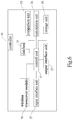
- FIG. 6 is a block diagram of a controller according to an embodiment of the present disclosure.
- the controller 30 is implemented as shown by FIG. 6 , but the controller 30 of the present disclosure is not limited thereto.
- the controller 30 may be implemented by a microcontroller accompanying with software.
- the controller 30 comprises a database 31 , a control unit 32 , a comparison unit 33 , a calculation unit 34 , a storage unit 35 , a wireless transceiver module 36 , an input interface module 37 and a output interface unit 38 .
- the control unit 32 is electrically connected to the database 31 , the comparison unit 33 , the calculation unit 34 , the storage unit 35 , the wireless transceiver module 36 , the input interface module 37 and the output interface unit 38 , and used to control operations of them.
- the database 31 is used to store the 3D image
- the comparison unit 33 is used to compare the 3D ultrasonic image with the 3D image.
- the calculation unit 34 is used to calculate the detection signals to generate the 3D ultrasonic image, and preferably, a modeling process is performed on the 3D ultrasonic image, such that the shape of the 3D ultrasonic image is similar to the actual shape of the tested object.
- the storage unit 35 can store each detection result of the surface detection and the statistic data.
- the wireless transceiver module 36 is used to make the controller 30 communicatively connected to other electronic devices via the wireless or wired manner.
- the input interface module 37 can acquire input data via the wireless or wired manner, and the output interface unit 38 can output data to other electronic devices via the wireless or wired manner.
- FIG. 7 is a flow chart of a surface detection method according to an embodiment of the present disclosure.
- the surface detection has steps as follows.
- step S 1 the above 3D detection device is provided, and the ultrasonic measuring is performed on the tested object which enters the detection supporter base, so as to obtain the 3D ultrasonic image.
- step S 2 the pre-established 3D image of the accepted object is acquired.
- step S 3 the 3D ultrasonic image is compared with the 3D image, so as determine whether the tested object has the defect.
- the detection result is output.
- FIG. 8 is a schematic diagram show the comparison of a 3D ultrasonic image of a tested object and a 3D image of an accepted object according to an embodiment of the present disclosure.
- the 3D ultrasonic image can be performed with the modeling process, such that the 3D ultrasonic image IMG having the shape similar to the actual shape of the tested object is obtained. Additionally, the 3D image is also performed with the modeling process, such that the 3D image IMGREF having the shape similar to the actual shape of the accepted object is obtained.
- FIG. 1 is a schematic diagram show the comparison of a 3D ultrasonic image of a tested object and a 3D image of an accepted object according to an embodiment of the present disclosure.
- the 3D ultrasonic image can be performed with the modeling process, such that the 3D ultrasonic image IMG having the shape similar to the actual shape of the tested object is obtained.
- the 3D image is also performed with the modeling process, such that the 3D image IMGREF having the shape similar to the actual shape of the accepted object is obtained.
- the 3D ultrasonic image IMG and the 3D image IMGREF are directly compared with each other to output a difference image RIMG, wherein the difference image RIMG has the surface defect pattern DP, and thus that the surfaces of the tested object have the defect is determined.
- the modeling processed 3D ultrasonic image IMG and the modeling processed 3D image IMGREF, and the difference image RIMG can be output to the display via the output interface unit, so as to provide intuitive visual information to related users.
- the 3D detection device and the surface detection method provided by the present disclosure utilize the ultrasonic measuring, and the 3D detection device is configured to have a detection supporter base. Without the light source, the reflected ultrasonic signals are easily received by the ultrasonic transceiver module, the quality of the detection signals is better, and thus it results a precise detection result, and decreases a detection time much. Further, the present disclosure is suitable for the requirement of the application of the automatically continuous processing process, and it provides a reliable and positive means for preventing the defective objects from being continuously generated, and for monitoring an availability of the production line apparatus. Moreover, without modifying, the 3D detection device can be directly installed in the current production line apparatus as well as additional grabbing devices, and thus the present disclosure has many industrial benefits.
Abstract
Description
Claims (12)
Priority Applications (1)
| Application Number | Priority Date | Filing Date | Title |
|---|---|---|---|
| US16/800,620 US11099158B2 (en) | 2018-05-11 | 2020-02-25 | Three dimensional detection device, surface detection method and production line apparatus using the same |
Applications Claiming Priority (2)
| Application Number | Priority Date | Filing Date | Title |
|---|---|---|---|
| US15/977,468 US20190346566A1 (en) | 2018-05-11 | 2018-05-11 | Surface detection method |
| US16/800,620 US11099158B2 (en) | 2018-05-11 | 2020-02-25 | Three dimensional detection device, surface detection method and production line apparatus using the same |
Related Parent Applications (1)
| Application Number | Title | Priority Date | Filing Date |
|---|---|---|---|
| US15/977,468 Continuation-In-Part US20190346566A1 (en) | 2018-05-11 | 2018-05-11 | Surface detection method |
Publications (2)
| Publication Number | Publication Date |
|---|---|
| US20200191954A1 US20200191954A1 (en) | 2020-06-18 |
| US11099158B2 true US11099158B2 (en) | 2021-08-24 |
Family
ID=71073538
Family Applications (1)
| Application Number | Title | Priority Date | Filing Date |
|---|---|---|---|
| US16/800,620 Active US11099158B2 (en) | 2018-05-11 | 2020-02-25 | Three dimensional detection device, surface detection method and production line apparatus using the same |
Country Status (1)
| Country | Link |
|---|---|
| US (1) | US11099158B2 (en) |
Families Citing this family (1)
| Publication number | Priority date | Publication date | Assignee | Title |
|---|---|---|---|---|
| CN112233068B (en) * | 2020-09-22 | 2023-04-18 | 电子科技大学 | Infrared imaging defect detection method of alternative convolution total variation regularization tensor decomposition |
Citations (8)
| Publication number | Priority date | Publication date | Assignee | Title |
|---|---|---|---|---|
| US5737084A (en) * | 1995-09-29 | 1998-04-07 | Takaoka Electric Mtg. Co., Ltd. | Three-dimensional shape measuring apparatus |
| US6878115B2 (en) * | 2002-03-28 | 2005-04-12 | Ultrasound Detection Systems, Llc | Three-dimensional ultrasound computed tomography imaging system |
| US8784203B2 (en) * | 2008-05-30 | 2014-07-22 | Sony Computer Entertainment America Llc | Determination of controller three-dimensional location using image analysis and ultrasonic communication |
| CN107133950A (en) * | 2017-05-22 | 2017-09-05 | 安徽信息工程学院 | Pass through detection method of the three-dimensional reconstruction to product quality |
| US9869753B2 (en) * | 2014-08-15 | 2018-01-16 | Quanergy Systems, Inc. | Three-dimensional-mapping two-dimensional-scanning lidar based on one-dimensional-steering optical phased arrays and method of using same |
| CN107860338A (en) * | 2017-12-08 | 2018-03-30 | 张宇航 | Industrial automation three-dimensional detection system and method |
| CN207816214U (en) * | 2017-12-08 | 2018-09-04 | 张宇航 | Industrial automation three-dimensional detection system |
| CN211926793U (en) * | 2020-06-11 | 2020-11-13 | 青岛谷岳机器人有限公司 | Rotation type 3D laser vision sensor |
-
2020
- 2020-02-25 US US16/800,620 patent/US11099158B2/en active Active
Patent Citations (8)
| Publication number | Priority date | Publication date | Assignee | Title |
|---|---|---|---|---|
| US5737084A (en) * | 1995-09-29 | 1998-04-07 | Takaoka Electric Mtg. Co., Ltd. | Three-dimensional shape measuring apparatus |
| US6878115B2 (en) * | 2002-03-28 | 2005-04-12 | Ultrasound Detection Systems, Llc | Three-dimensional ultrasound computed tomography imaging system |
| US8784203B2 (en) * | 2008-05-30 | 2014-07-22 | Sony Computer Entertainment America Llc | Determination of controller three-dimensional location using image analysis and ultrasonic communication |
| US9869753B2 (en) * | 2014-08-15 | 2018-01-16 | Quanergy Systems, Inc. | Three-dimensional-mapping two-dimensional-scanning lidar based on one-dimensional-steering optical phased arrays and method of using same |
| CN107133950A (en) * | 2017-05-22 | 2017-09-05 | 安徽信息工程学院 | Pass through detection method of the three-dimensional reconstruction to product quality |
| CN107860338A (en) * | 2017-12-08 | 2018-03-30 | 张宇航 | Industrial automation three-dimensional detection system and method |
| CN207816214U (en) * | 2017-12-08 | 2018-09-04 | 张宇航 | Industrial automation three-dimensional detection system |
| CN211926793U (en) * | 2020-06-11 | 2020-11-13 | 青岛谷岳机器人有限公司 | Rotation type 3D laser vision sensor |
Also Published As
| Publication number | Publication date |
|---|---|
| US20200191954A1 (en) | 2020-06-18 |
Similar Documents
| Publication | Publication Date | Title |
|---|---|---|
| JP5875352B2 (en) | Image processing apparatus, image processing apparatus control method, distance measurement apparatus, and program | |
| US10521898B2 (en) | Structural masking for progressive health monitoring | |
| US8233041B2 (en) | Image processing device and image processing method for performing three dimensional measurements | |
| EP2604180A1 (en) | Gaze point detection method and gaze point detection device | |
| JP7403526B2 (en) | Systems and methods for removable and attachable acoustic imaging sensors | |
| US10440217B2 (en) | Apparatus and method for processing three dimensional image | |
| US20110228052A1 (en) | Three-dimensional measurement apparatus and method | |
| CN109752722A (en) | Multi-modal acoustics imaging tool | |
| US11099158B2 (en) | Three dimensional detection device, surface detection method and production line apparatus using the same | |
| CN109752721A (en) | Portable acoustics imaging tool with scanning and analysis ability | |
| US20190057715A1 (en) | Deep neural network of multiple audio streams for location determination and environment monitoring | |
| JP2009289046A (en) | Operation support device and method using three-dimensional data | |
| US20150371105A1 (en) | System and method for frequency-based 3d reconstruction of objects | |
| KR101757240B1 (en) | Method for generating reference pattern of 3D shape measuring device | |
| CN113538428A (en) | Wood defect detection method, apparatus, medium, and computer program product | |
| US8502865B2 (en) | Mirror and adjustment method therefor | |
| US20190346566A1 (en) | Surface detection method | |
| KR101555685B1 (en) | Method and system for inspecting glass quality | |
| KR101695531B1 (en) | System for inspecting an object based on vision image | |
| US9311515B2 (en) | Automatic tuning of scanner lighting | |
| KR101276204B1 (en) | Method for measuring environmental parameters for multi-modal fusion | |
| KR20200087331A (en) | Apparatus and method for inspecting steel products | |
| CN103901039A (en) | Detection system | |
| Le et al. | Electrical colored wires inspection algorithm for automatic connector producing machines | |
| KR102258657B1 (en) | Product location tracking system using 2d design drawings and computer vision |
Legal Events
| Date | Code | Title | Description |
|---|---|---|---|
| AS | Assignment |
Owner name: WANG, HSIEN-KUO, TAIWAN Free format text: ASSIGNMENT OF ASSIGNORS INTEREST;ASSIGNORS:LIN, CHIH-CHIEH;WANG, HSIEN-KUO;REEL/FRAME:051924/0272 Effective date: 20200221 Owner name: LIN, CHIH-CHIEH, TAIWAN Free format text: ASSIGNMENT OF ASSIGNORS INTEREST;ASSIGNORS:LIN, CHIH-CHIEH;WANG, HSIEN-KUO;REEL/FRAME:051924/0272 Effective date: 20200221 Owner name: GAUSS DESIGN INC, TAIWAN Free format text: ASSIGNMENT OF ASSIGNORS INTEREST;ASSIGNORS:LIN, CHIH-CHIEH;WANG, HSIEN-KUO;REEL/FRAME:051924/0272 Effective date: 20200221 |
|
| FEPP | Fee payment procedure |
Free format text: ENTITY STATUS SET TO UNDISCOUNTED (ORIGINAL EVENT CODE: BIG.); ENTITY STATUS OF PATENT OWNER: SMALL ENTITY |
|
| FEPP | Fee payment procedure |
Free format text: ENTITY STATUS SET TO SMALL (ORIGINAL EVENT CODE: SMAL); ENTITY STATUS OF PATENT OWNER: SMALL ENTITY |
|
| STPP | Information on status: patent application and granting procedure in general |
Free format text: DOCKETED NEW CASE - READY FOR EXAMINATION |
|
| STPP | Information on status: patent application and granting procedure in general |
Free format text: NON FINAL ACTION MAILED |
|
| STPP | Information on status: patent application and granting procedure in general |
Free format text: RESPONSE TO NON-FINAL OFFICE ACTION ENTERED AND FORWARDED TO EXAMINER |
|
| STPP | Information on status: patent application and granting procedure in general |
Free format text: NOTICE OF ALLOWANCE MAILED -- APPLICATION RECEIVED IN OFFICE OF PUBLICATIONS |
|
| STPP | Information on status: patent application and granting procedure in general |
Free format text: PUBLICATIONS -- ISSUE FEE PAYMENT RECEIVED |
|
| STCF | Information on status: patent grant |
Free format text: PATENTED CASE |