US11047434B2 - One-way clutch operable with one or no races and without race pockets for locking elements - Google Patents
One-way clutch operable with one or no races and without race pockets for locking elements Download PDFInfo
- Publication number
- US11047434B2 US11047434B2 US12/738,747 US73874708A US11047434B2 US 11047434 B2 US11047434 B2 US 11047434B2 US 73874708 A US73874708 A US 73874708A US 11047434 B2 US11047434 B2 US 11047434B2
- Authority
- US
- United States
- Prior art keywords
- pawl
- stator
- way clutch
- plates
- rotatable component
- Prior art date
- Legal status (The legal status is an assumption and is not a legal conclusion. Google has not performed a legal analysis and makes no representation as to the accuracy of the status listed.)
- Active, expires
Links
Images


Classifications
-
- F—MECHANICAL ENGINEERING; LIGHTING; HEATING; WEAPONS; BLASTING
- F16—ENGINEERING ELEMENTS AND UNITS; GENERAL MEASURES FOR PRODUCING AND MAINTAINING EFFECTIVE FUNCTIONING OF MACHINES OR INSTALLATIONS; THERMAL INSULATION IN GENERAL
- F16D—COUPLINGS FOR TRANSMITTING ROTATION; CLUTCHES; BRAKES
- F16D41/00—Freewheels or freewheel clutches
- F16D41/12—Freewheels or freewheel clutches with hinged pawl co-operating with teeth, cogs, or the like
-
- F—MECHANICAL ENGINEERING; LIGHTING; HEATING; WEAPONS; BLASTING
- F16—ENGINEERING ELEMENTS AND UNITS; GENERAL MEASURES FOR PRODUCING AND MAINTAINING EFFECTIVE FUNCTIONING OF MACHINES OR INSTALLATIONS; THERMAL INSULATION IN GENERAL
- F16D—COUPLINGS FOR TRANSMITTING ROTATION; CLUTCHES; BRAKES
- F16D41/00—Freewheels or freewheel clutches
- F16D41/06—Freewheels or freewheel clutches with intermediate wedging coupling members between an inner and an outer surface
- F16D41/069—Freewheels or freewheel clutches with intermediate wedging coupling members between an inner and an outer surface the intermediate members wedging by pivoting or rocking, e.g. sprags
-
- F—MECHANICAL ENGINEERING; LIGHTING; HEATING; WEAPONS; BLASTING
- F16—ENGINEERING ELEMENTS AND UNITS; GENERAL MEASURES FOR PRODUCING AND MAINTAINING EFFECTIVE FUNCTIONING OF MACHINES OR INSTALLATIONS; THERMAL INSULATION IN GENERAL
- F16H—GEARING
- F16H41/00—Rotary fluid gearing of the hydrokinetic type
- F16H41/24—Details
- F16H2041/246—Details relating to one way clutch of the stator
Definitions
- the present disclosure generally relates to transmission components, and more particularly relates to one-way clutches used in transmission components.
- One-way clutches are commonly employed devices to allow for controlled transmission of rotational energy. More specifically, a one-way clutch can be used to allow for two rotational components to move in unison when the components are moved relative to each other in a first direction, but disengage and not allow relative rotation when moved in the opposite direction.
- Such clutches are well-known and can be of various types including, but not limited to, sprag type one-way clutches, roller-type one-way clutches, and pawl or ratchet type one-way clutches.
- one-way clutch employed for a given transmission application will be dictated by a number of parameters including, but not limited to, the desired load capacity for the clutch, and space limitations in the machine employing the clutch. For example, sprag and roller type one-way clutches typically require a smaller dimensional footprint than a ratchet or pawl clutch, but at the same time provide lesser load capacities.
- One particular application which may employ a one-way radial ratchet clutch is in the coupling between a rotating drive shaft of a vehicle transmission and a torque converter of the transmission.
- a torque converter of the transmission When increased torque is demanded by the vehicle employing the transmission, for example during acceleration, it may be desirable for the rotating components of the torque converter to be engaged with the drive shaft. In other situations, such as idling, or when the vehicle attains speed, it may be desirable for the two components to be disengaged.
- a one-way clutch can be positioned between a stator and stator support of the torque converter to allow for such selective engagement and disengagement.
- such a one-way radial ratchet clutch would include an inner race and an outer race with a ratchet or a pawl provided between the inner and outer races.
- the pawl can be oriented so as to engage or disengage from notches provided either in the inner or outer race.
- the torque converter When it is desired for the torque converter to be activated, the pawl can be engaged with one of the notches to join the components together in rotation. Once sufficient torque has been provided, the one-way clutch can be disengaged, to allow for the inner race to free-wheel.
- a one-way clutch assembly which may include a first plate, a second plate, and a friction member rotatably mounted between the first and second plates, wherein the friction member may be adapted to directly engage an adjacent rotatable component of a transmission without any races being employed.
- a one-way clutch which may include a first rotatable component of a transmission, a second rotatable component of a transmission, a first plate positioned between the first rotatable component and the second rotatable component, a second plate positioned between the first rotatable component and the second rotatable component, and a pawl rotatably mounted between the first and second plates, wherein the pawl may be adapted to directly engage one of the rotatable components, and wherein at least one of the rotatable components may include at least one notch provided therein for receipt of the pawl.
- a one-way clutch which may include first and second outer connected annular plates which may be axially spaced from one another.
- An inner race may be rotatably mounted with respect to one of the plates and the inner race may have a ratchet surface.
- Ratchet pawls may be pivotably mounted with respect to the plates and have unidirectional engagement with the ratchet surface of the inner race.
- FIG. 1 is a sectional view of a portion of a transmission employing a prior art one-way clutch
- FIG. 2 is a schematic representation of the prior art one-way clutch of FIG. 1 ;
- FIG. 3 a schematic representation of a one-way clutch constructed in accordance with the teachings of the disclosure and employing only one race;
- FIG. 4 is a schematic representation of a second embodiment of a one-way clutch constructed in accordance with the teachings of the disclosure and employing no races;
- FIG. 5 is a schematic representation of a third embodiment of a one-way clutch constructed in accordance with the teachings of the disclosure and also using no races, but orienting the pawl in an opposite direction to that of the second embodiment;
- FIG. 6 is a plan view of a one-way clutch constructed in accordance with the teachings of the disclosure.
- FIG. 7 is a sectional view of the one-way clutch of FIG. 6 , and taken along line 7 - 7 of FIG. 6 .
- FIG. 8 is a schematic representation of a fourth embodiment of a one-way clutch constructed in accordance with the teachings of the disclosure, but without any side plates;
- FIG. 9 is a schematic representation of a fifth embodiment of a one-way clutch similar to that of FIG. 8 , but also without any races;
- FIG. 11 is an enlarged perspective view of the one-way clutch shown in FIG. 10 with part of the outer race provided by a plate being removed for clarity of illustration;
- FIG. 12 is a perspective view of a seventh embodiment of a one-way clutch according to the present invention.
- FIG. 13 is an enlarged perspective view of the clutch shown in FIG. 12 with a plate of the outer race being removed for clarity of illustration;
- FIG. 14 is an enlarged perspective view similar to FIG. 13 but of an eighth embodiment of a one-way clutch according to the present disclosure
- FIG. 15 is an enlarged perspective view similar to FIG. 13 of a ninth embodiment of a one-way clutch according to the present disclosure.
- FIG. 16 is a schematic view of a tenth embodiment of a one-way clutch according to the present disclosure wherein a carrier provides one of the plates for the outer race.
- a prior art transmission assembly may be generally referred to by reference numeral 20 . While a particular transmission assembly 20 may be depicted, it is to be understood that FIG. 1 may be provided mainly for the purpose of depicting the prior art to more easily exemplify the differences and benefits provided by the present disclosure represented in the latter figures.
- the transmission assembly 20 of FIG. 1 may be but one example of the setting in which a one-way clutch may be employed.
- Other areas of a transmission, vehicle, machine tool, or other machine may also be advantageously employ its teachings as will be readily understood by one of ordinary skill in the art.
- the transmission 20 may include a central drive shaft 22 adapted to rotate about axis 24 , which may be itself powered by the motive force of an engine (not shown) of a vehicle (also not shown). Positioned radially about the shaft 22 may be a torque converter 26 .
- a torque converter 26 Positioned radially about the shaft 22 may be a torque converter 26 .
- the torque converter 26 may be typically employed by automatic transmissions to transfer engine torque to the transmission, allow the vehicle to come to a stop while not stalling, and selectively multiply the torque provided by the engine before transferring torque to the drive train of the vehicle.
- the torque converter 26 may include a stator 28 and a stator support 30 .
- the additional torque provided by the torque converter 26 may be called upon or not.
- a one-way clutch 36 may be mounted between the stator 28 and stator support 30 to selectively engage the two components. For example, when the added torque may be required by the vehicle, the torque converter from the one-way clutch can be engaged, and when not needed, the one-way clutch 32 can be disengaged to allow the stator 28 to free-wheel about the stator support 30 .
- the one-way clutch of FIG. 1 is also shown schematically in FIG. 2 for better understanding and illustration of the components, and may be illustrated as a sprag-type one-way clutch.
- the one-way clutch 32 may include an inner race 33 provided radially adjacent the stator support 30 , as well as an outer race 34 surrounding the inner race 33 .
- a moveable sprag 35 may be typically provided between the inner and outer races 33 , 34 . More specifically, a plurality of sprags 35 may be provided to circumferentially surround the inner and outer races 33 and 34 , but in sectional view of FIG.
- sprags 35 can be mounted for rotation in any number of different manners, but in the depicted embodiment it can be seen that a trunnion 36 may extend from both sides of the sprag 35 for mounting in bores provided in first and second discs 37 , 38 . Alternatively, a separate pin can be used for pivotal mounting of the sprag 35 .
- the sprags 35 may be substantially figure-eight shaped with curved ends 40 and 42 so that when one of the races 33 , 34 move in a first direction, the sprags 35 pivot and bind the two races together for simultaneous rotation, and when that race is moved in an opposite, second direction, the two races may not be bound together, but rather free-wheel relative to each other.
- the overall size, diameter, and weight of the torque converter 26 , and transmission assembly 20 itself may be somewhat dictated by the inclusion of the one-way clutch 32 .
- Space may be necessarily provided for mounting of the inner and outer races 33 and 34 , as well as the sprags 35 .
- splines or the like may need to be machined in the various components of the transmission, including but not limited to, the engagement between the inner race 33 and stator support 30 . While effective, such features may add material and labor costs to the transmission and vehicle, and impose weight and size penalties on the transmission and vehicle as well, penalties which may be increasingly undesirable in the modern marketplace with its ever increasing fuel costs.
- FIG. 3 a schematic representation of a first embodiment of the present disclosure is depicted.
- the one-way clutch of the present disclosure may be generally referred to by reference numeral 44 , and may be depicted as a radial ratchet type one-way clutch.
- the radial ratchet one-way clutch 44 may include a first mounting plate 46 , an adjacent, parallel, second mounting plate 48 , and a mounting pin 50 which may extend between the first and second plates 46 and 48 and may allow for a pawl 52 to rotate or pivot thereabout.
- the pin 50 may be internal to the pawl 52 in the form of a trunnion or the like.
- the first and second plates 46 and 48 , as well pin 50 and pawl 52 may extend from the stator support 54 .
- the plates 46 and 48 , pin 50 , and pawl 52 may be fixed to the stator support 54 and may be selectively engageable with only a single race, in this case an outer race 56 .
- the outer race 56 may be in turn provided in engagement with the stator 58 .
- the stator support 54 may provide radial support of the drive shaft 59 via a bushing knot shown).
- both the inner and outer races may be removed.
- the first and second plates 46 and 48 may be provided with the pin 50 extending therebetween, and the pawl 52 may be adapted to rotate about the pin 50 .
- the pawl 52 may engage directly with the stator 58 .
- a plurality of notches 61 may be provided not in a race of any kind, but directly within the stator 58 itself. As shown in FIG. 6 , each of the notches 61 may be canted in the same direction so as to have a cam surface 62 and a shoulder 63 .
- a radial ratchet one-way clutch operable with no races may be provided.
- the first and second plates, 46 and 48 may extend directly from the stator 58 .
- the pawls 52 may selectively engage the notches 61 provided within the stator support 54 , as opposed to the stator 58 . While operating in an opposite direction, the one-way clutch with no-race functionality may be still afforded.
- a central drive shaft 59 rotates about an axis 60 .
- FIGS. 6 and 7 a more detailed rendering of a radial ratchet one-way clutch 44 constructed in accordance with teachings of the disclosure is shown.
- a plan view is depicted showing that the first and second plates 46 , 48 may be provided in a plurality of matching sets about the circumference of the clutch.
- the first and second sets of plates 46 and 48 may extend radially inwardly from the stator 58 , and in turn the plurality of pawls 52 may be adapted to engage a plurality of notches 61 provided in the stator support 54 .
- a total of twenty-two notches 61 may be shown in FIG.
- each pawl 52 may be biased by a spring 64 into an inward position, i.e., toward the notches 61 .
- the inward position corresponds to the engaged position, wherein the pawls 52 may be forced into engagement with notches 61 , thereby engaging the stator 58 with the stator support 54 .
- the pawl 52 can be caused to be centrifugally disengaged from notches 61 upon reaching a certain speed. In other words, upon reaching a specific RPM, the centrifugal force thereby generated will overpower the biasing force of the spring, and thus cause disengagement.
- a pin 80 could extend between existing components of the transmission 20 . More specifically, as shown in FIG. 8 , in one embodiment the pin 80 could extend between a plate 82 integral to the stator 84 and a thrust washer 86 already existing on the transmission 20 . A pawl 88 can then be rotatably mounted to the pin 80 for selective engagement with an inner race 90 , itself mounted to a stator support 92 .
- the embodiment of FIG. 9 is similar to that of FIG. 8 , but for the removal of the inner race 90 thereby allowing for direct engagement of the pawl 88 with the stator support 92 . In so doing, it can be seen that the present disclosure may allow for production without any side plates and/or inner or outer races.
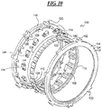
- FIGS. 10 and 11 illustrate another one-way clutch 100 according to the present disclosure.
- the clutch 100 may include an inner race 102 .
- the inner race 102 may have an inner cylinder 104 .
- the inner cylinder 104 may have an inner diameter 106 with spline teeth 108 allowing it to be connected with a rotating shaft or carrier (not shown).
- Integrally connected and axially slightly displaced from the inner cylinder 104 may be an outer cylinder 110 .
- the outer cylinder 110 along its outer diameter may have a ratchet surface 112 .
- An outer race 114 may be provided by first and second axially spaced plates 116 and 118 .
- the plates 116 and 118 both have tabs 120 to allow the plates 116 and 118 to be torsionally affixed with a casing structure of a transmission (not shown).
- the concentricity control between the inner race 102 and the outer race subassembly 114 may be controlled external to the clutch 100 .
- clutch 100 may be non-concentrically controlling. Extending between the plates 116 , 118 and connecting the same may be fasteners 122 .
- the fasteners 122 may be typically threaded type fasteners having a shank threaded into blind bores extending into the plates 116 , but could be rivets, knurled pins, welded pins, bonded pins, epoxy pins, or the like.
- the fasteners 122 may have a head or nut (not shown in all figures) abutting against the surface 124 of the plate 118 .
- Additionally extending between the plates 116 and 118 may be a series of fastener shanks or pins 126 . Extending between and connected with plates 116 and 118 may be a series of spring mounts 128 .
- the spring mounts 128 may have extending barbs 130 that enter into corresponding slots 132 provided in a board surface of the plates 116 , 118 . Pivotally connected on the plates 116 and 118 via the pins 122 may be pawls 134 .
- the pawl 134 may have a cylindrical slot 136 that may be open for less than 180° so as to hold on to the pin 122 .
- the pawl 134 may have an indention 138 for receipt and capture of a spring 140 positioned between the indention 138 and the spring mount 128 .
- the spring 140 may be a bent strip type spring.
- the pawl 134 may have an engagement head 142 for unidirectional engagement with a ratchet notch 144 of the ratchet surface 112 . (In FIG. 11 , the springs are not shown for clarity of the illustration.)
- FIGS. 12 and 13 illustrate an alternative clutch 150 of the present disclosure having a position limiter 152 .
- Each pawl 154 of this embodiment may have a head 156 with a concave curvilinear edge surface 158 for engagement with the fasteners 122 .
- the pawl 154 also may have generally opposing the surface 158 a concave curvilinear edge surface 162 for engagement with the pin 126 .
- another alternative embodiment clutch 200 of the present disclosure may have adjacent weldments 202 and 204 to hold the plates 116 and 118 together. (Plate 118 is not shown in FIG. 12 ). Positioned in a gap 205 between the adjacent weldments 202 and 204 may be the pawl 154 .
- the weldment 202 may have a convex surface 206 for engagement with the concave surface 158 of the pawl 154 .
- weldment 204 may have a tip 208 to engage the surface 162 with pawl 154 .
- the weldment 204 also may have an arm 210 for mounting a spring 211 (not shown) that biases the pawl 154 into engagement with a ratchet surface 212 of the inner race 102 .
- the ratchet surface 212 may have unidirectional engagement with a pawl 214 (not shown) carried by the outer race 114 via pin 216 (not shown).
- FIG. 15 another embodiment of the present disclosure has a clutch 250 with weldments 252 .
- the weldments 252 may be common with one another having an end substantially similar to the previously described weldment 202 and an opposite, end substantially similar to the weldment 204 .
- yet another embodiment of the present disclosure is a clutch 300 provided in the environment of a transmission 302 .
- the transmission 302 may have a support 304 that may be fixed with respect to a casing or structural frame of the transmission.
- the support 304 may have a cylindrical portion 306 that encircles a shaft 308 .
- An outer diameter 310 of the cylindrical portion may be splined to an inner race portion 312 of the clutch 300 .
- the outer race 314 may have one side plate 316 which may be integral with a carrier 318 of the transmission.
- Carrier 318 may have a shaft 320 that may mount a planetary gear 322 .
- Connecting the plate 316 with the outer plate 324 of the outer race 314 may be a series of fastener pins 326 .
- the outer race 314 may be connected with friction discs 328 via the pins 326 .
- the pins 326 can extend through the discs 328 or the discs can be mounted on an outer diameter 330 of the pins 326 .
- the discs 328 along with separator plates 331 form a friction pack 332 that can be actuated by a piston 334 .
- the present disclosure sets forth a one-way clutch which can function with one or no races or with a race having no race pockets for locking elements.
- the overall size and weight requirements of the one-way clutch are drastically reduced, which in turn reduces the overall weight and size requirements of the torque converter and transmission, or other rotating components with which it is used, as well.
- Such improvements can directly translate into lower material and labor manufacturing costs, better transmission efficiency, and higher vehicle fuel economy.
- the teachings of this disclosure can be employed to remove races of any type of one-way clutch, including radial ratchet type, sprag type, and roller type one-way clutches.
Landscapes
- Engineering & Computer Science (AREA)
- General Engineering & Computer Science (AREA)
- Mechanical Engineering (AREA)
- Mechanical Operated Clutches (AREA)
- Rolling Contact Bearings (AREA)
Abstract
Description
Claims (5)
Priority Applications (1)
| Application Number | Priority Date | Filing Date | Title |
|---|---|---|---|
| US12/738,747 US11047434B2 (en) | 2007-10-19 | 2008-10-20 | One-way clutch operable with one or no races and without race pockets for locking elements |
Applications Claiming Priority (4)
| Application Number | Priority Date | Filing Date | Title |
|---|---|---|---|
| US99970007P | 2007-10-19 | 2007-10-19 | |
| US4363808P | 2008-04-09 | 2008-04-09 | |
| US12/738,747 US11047434B2 (en) | 2007-10-19 | 2008-10-20 | One-way clutch operable with one or no races and without race pockets for locking elements |
| PCT/US2008/080506 WO2009052499A2 (en) | 2007-10-19 | 2008-10-20 | One-way clutch operable with one or no races and without race pockets for locking elements |
Publications (2)
| Publication Number | Publication Date |
|---|---|
| US20100288592A1 US20100288592A1 (en) | 2010-11-18 |
| US11047434B2 true US11047434B2 (en) | 2021-06-29 |
Family
ID=40568108
Family Applications (1)
| Application Number | Title | Priority Date | Filing Date |
|---|---|---|---|
| US12/738,747 Active 2031-07-09 US11047434B2 (en) | 2007-10-19 | 2008-10-20 | One-way clutch operable with one or no races and without race pockets for locking elements |
Country Status (2)
| Country | Link |
|---|---|
| US (1) | US11047434B2 (en) |
| WO (1) | WO2009052499A2 (en) |
Families Citing this family (17)
| Publication number | Priority date | Publication date | Assignee | Title |
|---|---|---|---|---|
| DE102010033072B4 (en) | 2009-08-28 | 2019-07-11 | Schaeffler Technologies AG & Co. KG | Dry freewheel between starter and clutch |
| WO2012073309A1 (en) * | 2010-11-29 | 2012-06-07 | トヨタ自動車 株式会社 | Internal combustion engine and method for assembling internal combustion engine |
| US20120285783A1 (en) * | 2011-05-09 | 2012-11-15 | Carlos Raul Espinosa-Montalvo | One-way cluth |
| US8844693B2 (en) | 2011-09-13 | 2014-09-30 | Means Industries, Inc. | Coupling assembly having an overrun mode and ratcheting reverse strut or radial ratchet for use therein |
| US8881516B2 (en) | 2012-02-17 | 2014-11-11 | Ford Global Technologies, Llc | One-way brake for a torque converter stator |
| US9051980B2 (en) | 2013-04-26 | 2015-06-09 | Gm Global Technology Operations, Llc | Direction selectable sprag |
| US9669656B2 (en) * | 2013-08-20 | 2017-06-06 | Shimano (Singapore) Pte. Ltd. | Bicycle freewheel |
| DE102015218291A1 (en) | 2014-09-30 | 2016-03-31 | Schaeffler Technologies AG & Co. KG | Toggle overrunning clutch with recess for receiving a spring and a stator containing the same |
| JP6323397B2 (en) * | 2015-06-02 | 2018-05-16 | トヨタ自動車株式会社 | One-way clutch mounting structure |
| US10272992B2 (en) * | 2015-10-31 | 2019-04-30 | Borealis Technical Limited | Clutch assembly for aircraft drive wheel drive system |
| US10145428B2 (en) | 2016-02-04 | 2018-12-04 | Means Industries, Inc. | Coupling assembly having an overrun mode and channeled locking member for use therein |
| US10316904B2 (en) | 2016-09-28 | 2019-06-11 | Means Industries, Inc. | Coupling assembly having an overrun mode and appendaged locking member for use therein |
| DE102019008865A1 (en) * | 2019-12-18 | 2021-06-24 | Borgwarner Inc. | Freewheel |
| JP7416526B2 (en) | 2020-03-30 | 2024-01-17 | Nskワーナー株式会社 | ratchet type clutch |
| CN111336193A (en) * | 2020-04-02 | 2020-06-26 | 南京苏孚乐遮阳科技有限公司 | One-way transmission structure and solar protection devices |
| US11384724B2 (en) | 2020-05-31 | 2022-07-12 | Borgwarner Inc. | Permanently engaged starter system |
| US11739801B2 (en) | 2020-06-02 | 2023-08-29 | Means Industries, Inc. | Coupling assembly and ratcheting locking member for use therein |
Citations (25)
| Publication number | Priority date | Publication date | Assignee | Title |
|---|---|---|---|---|
| US1767593A (en) * | 1927-11-09 | 1930-06-24 | Cutler Hammer Inc | Clutch |
| US2232090A (en) * | 1938-12-14 | 1941-02-18 | Kinney Mfg Company | Overrunning clutch |
| US2323353A (en) * | 1940-12-18 | 1943-07-06 | William H Plog | One-way clutch |
| US2710504A (en) * | 1952-06-06 | 1955-06-14 | Adiel Y Dodge | Toroidal chamber type hydraulic torque converter |
| US3545581A (en) * | 1968-12-19 | 1970-12-08 | Borg Warner | Sprag assembly for one-way clutches |
| US3702649A (en) * | 1970-01-31 | 1972-11-14 | Ringspann Maurer Kg A | One-way clutch having tiltable sprags |
| US3844391A (en) * | 1972-03-27 | 1974-10-29 | Borg Warner Stieber Gmbh | Sprag type freewheel clutch |
| US4187728A (en) * | 1977-01-31 | 1980-02-12 | Societe De Paris Et Du Rhone | Unidirectional drive systems |
| US4275805A (en) * | 1978-06-05 | 1981-06-30 | Crankshaw John H | Overrunning clutch |
| US4548316A (en) * | 1982-12-08 | 1985-10-22 | Ringspann Albrecht Maurer, K.G. | Run-back safety mechanism for conveyor apparatus |
| US5125487A (en) * | 1990-08-31 | 1992-06-30 | Ina Bearing Company, Inc. | Method and apparatus for providing torque converter having improved stator/clutch assembly |
| US5156245A (en) | 1990-09-25 | 1992-10-20 | Koyo Seikyo Co., Ltd. | One-way clutch free from gear-tooth noise |
| US5383542A (en) * | 1993-12-27 | 1995-01-24 | Ford Motor Company | Overrunning clutch |
| US5855263A (en) * | 1996-12-20 | 1999-01-05 | Eaton Corporation | One-way clutch and torque converter stator |
| US5966985A (en) | 1996-10-22 | 1999-10-19 | Kawasaki Jukogyo Kabushiki Kaisha | Engine starter |
| US6167998B1 (en) | 1998-01-12 | 2001-01-02 | Nsk-Warner K.K. | One-way clutch |
| US6338403B1 (en) * | 1996-09-03 | 2002-01-15 | Borgwarner Inc. | Ratchet clutch with bearing surfaces |
| US20020005326A1 (en) * | 2000-06-22 | 2002-01-17 | Nsk-Warner K.K. | Ratchet one-way clutch |
| US20020153217A1 (en) * | 2001-04-18 | 2002-10-24 | Yutaka Giken Co., Ltd. | One-way clutch |
| US6814203B2 (en) | 2002-06-10 | 2004-11-09 | Nsk-Warner K.K. | Stator with one-way clutch |
| US6855085B1 (en) * | 1999-10-16 | 2005-02-15 | Zf Friedrichshafen Ag | Continuously variable vehicle transmission |
| US20060021840A1 (en) * | 2004-07-27 | 2006-02-02 | John Kimes | Ratcheting one-way clutch having rockers |
| US20070205069A1 (en) * | 2006-03-06 | 2007-09-06 | Keshtkar Hossein E | One-way pawl clutch with backlash reduction means and without biasing means |
| US20100075799A1 (en) * | 2008-09-25 | 2010-03-25 | Jatco Ltd | Continuously variable transmission and control method thereof |
| US7878316B2 (en) * | 2007-10-09 | 2011-02-01 | GM Global Technology Operations LLC | High torque one way clutch |
-
2008
- 2008-10-20 US US12/738,747 patent/US11047434B2/en active Active
- 2008-10-20 WO PCT/US2008/080506 patent/WO2009052499A2/en active Application Filing
Patent Citations (26)
| Publication number | Priority date | Publication date | Assignee | Title |
|---|---|---|---|---|
| US1767593A (en) * | 1927-11-09 | 1930-06-24 | Cutler Hammer Inc | Clutch |
| US2232090A (en) * | 1938-12-14 | 1941-02-18 | Kinney Mfg Company | Overrunning clutch |
| US2323353A (en) * | 1940-12-18 | 1943-07-06 | William H Plog | One-way clutch |
| US2710504A (en) * | 1952-06-06 | 1955-06-14 | Adiel Y Dodge | Toroidal chamber type hydraulic torque converter |
| US3545581A (en) * | 1968-12-19 | 1970-12-08 | Borg Warner | Sprag assembly for one-way clutches |
| US3702649A (en) * | 1970-01-31 | 1972-11-14 | Ringspann Maurer Kg A | One-way clutch having tiltable sprags |
| US3844391A (en) * | 1972-03-27 | 1974-10-29 | Borg Warner Stieber Gmbh | Sprag type freewheel clutch |
| US4187728A (en) * | 1977-01-31 | 1980-02-12 | Societe De Paris Et Du Rhone | Unidirectional drive systems |
| US4275805A (en) * | 1978-06-05 | 1981-06-30 | Crankshaw John H | Overrunning clutch |
| US4548316A (en) * | 1982-12-08 | 1985-10-22 | Ringspann Albrecht Maurer, K.G. | Run-back safety mechanism for conveyor apparatus |
| US5125487A (en) * | 1990-08-31 | 1992-06-30 | Ina Bearing Company, Inc. | Method and apparatus for providing torque converter having improved stator/clutch assembly |
| US5156245A (en) | 1990-09-25 | 1992-10-20 | Koyo Seikyo Co., Ltd. | One-way clutch free from gear-tooth noise |
| US5383542A (en) * | 1993-12-27 | 1995-01-24 | Ford Motor Company | Overrunning clutch |
| US6338403B1 (en) * | 1996-09-03 | 2002-01-15 | Borgwarner Inc. | Ratchet clutch with bearing surfaces |
| US5966985A (en) | 1996-10-22 | 1999-10-19 | Kawasaki Jukogyo Kabushiki Kaisha | Engine starter |
| US5855263A (en) * | 1996-12-20 | 1999-01-05 | Eaton Corporation | One-way clutch and torque converter stator |
| US6167998B1 (en) | 1998-01-12 | 2001-01-02 | Nsk-Warner K.K. | One-way clutch |
| US6855085B1 (en) * | 1999-10-16 | 2005-02-15 | Zf Friedrichshafen Ag | Continuously variable vehicle transmission |
| US20020005326A1 (en) * | 2000-06-22 | 2002-01-17 | Nsk-Warner K.K. | Ratchet one-way clutch |
| US6612107B2 (en) * | 2001-04-18 | 2003-09-02 | Yutaka Giken Co., Ltd. | One-way clutch |
| US20020153217A1 (en) * | 2001-04-18 | 2002-10-24 | Yutaka Giken Co., Ltd. | One-way clutch |
| US6814203B2 (en) | 2002-06-10 | 2004-11-09 | Nsk-Warner K.K. | Stator with one-way clutch |
| US20060021840A1 (en) * | 2004-07-27 | 2006-02-02 | John Kimes | Ratcheting one-way clutch having rockers |
| US20070205069A1 (en) * | 2006-03-06 | 2007-09-06 | Keshtkar Hossein E | One-way pawl clutch with backlash reduction means and without biasing means |
| US7878316B2 (en) * | 2007-10-09 | 2011-02-01 | GM Global Technology Operations LLC | High torque one way clutch |
| US20100075799A1 (en) * | 2008-09-25 | 2010-03-25 | Jatco Ltd | Continuously variable transmission and control method thereof |
Non-Patent Citations (1)
| Title |
|---|
| International Search Report PCT/US2008/080506; report filed Jul. 17, 2009. |
Also Published As
| Publication number | Publication date |
|---|---|
| WO2009052499A2 (en) | 2009-04-23 |
| WO2009052499A3 (en) | 2009-09-03 |
| US20100288592A1 (en) | 2010-11-18 |
Similar Documents
| Publication | Publication Date | Title |
|---|---|---|
| US11047434B2 (en) | One-way clutch operable with one or no races and without race pockets for locking elements | |
| US10393190B2 (en) | Decoupler with concentric clutching members | |
| EP2715171B1 (en) | Isolator decoupler | |
| US5823880A (en) | Dual flywheel assembly with lockup mechanism between two flywheels | |
| JP5561898B2 (en) | Wedge type one-way clutch | |
| US20120234131A1 (en) | Dual-mass flywheel lock-out clutch | |
| JP5352456B2 (en) | Roller, sprag or ratchet one-way clutch with two backing plates | |
| US8376900B2 (en) | Clutch assembly | |
| CN101960163A (en) | Decoupling isolator | |
| JP2016508582A (en) | Multi-mode clutch module | |
| US10850602B2 (en) | Hybrid powertrain engine disconnect device | |
| JP2013517175A (en) | Hybrid electric vehicle drive system and control system for controlling hybrid electric vehicle drive system | |
| US9568049B2 (en) | Torque transmission device for a motor vehicle | |
| JP2015521723A (en) | Attached device drive cutting device | |
| JP2017532513A (en) | Torsional absorption sprocket with locking mechanism | |
| JPS6323007B2 (en) | ||
| CA2637537A1 (en) | Power transmission damper for a torque limiter | |
| CN112585369A (en) | Friction clutch | |
| US10473170B2 (en) | Centrifugally disengaging multi-mode clutch module | |
| JP3378100B2 (en) | Clutch structure | |
| US11708872B2 (en) | Shiftable bidirectional freewheel clutch device, and drive device for a motor vehicle comprising the clutch device | |
| JP2008157449A (en) | Integral one-way clutch | |
| JPS581306B2 (en) | automatic transmission | |
| JPH0251625A (en) | Spring clutch | |
| JP3920964B2 (en) | Flywheel assembly |
Legal Events
| Date | Code | Title | Description |
|---|---|---|---|
| AS | Assignment |
Owner name: BORGWARNER, INC., MICHIGAN Free format text: ASSIGNMENT OF ASSIGNORS INTEREST;ASSIGNORS:PAPANIA, JAMES R.;SLAGER, DOUGLAS;HORNER, ANDREW;REEL/FRAME:024254/0733 Effective date: 20100409 |
|
| AS | Assignment |
Owner name: BORGWARNER, MICHIGAN Free format text: ASSIGNMENT OF ASSIGNORS INTEREST;ASSIGNOR:KOS, THOMAS;REEL/FRAME:024404/0690 Effective date: 20100416 |
|
| STPP | Information on status: patent application and granting procedure in general |
Free format text: NON FINAL ACTION MAILED |
|
| STPP | Information on status: patent application and granting procedure in general |
Free format text: RESPONSE TO NON-FINAL OFFICE ACTION ENTERED AND FORWARDED TO EXAMINER |
|
| STPP | Information on status: patent application and granting procedure in general |
Free format text: FINAL REJECTION MAILED |
|
| STPP | Information on status: patent application and granting procedure in general |
Free format text: RESPONSE AFTER FINAL ACTION FORWARDED TO EXAMINER |
|
| STPP | Information on status: patent application and granting procedure in general |
Free format text: ADVISORY ACTION MAILED |
|
| STPP | Information on status: patent application and granting procedure in general |
Free format text: DOCKETED NEW CASE - READY FOR EXAMINATION |
|
| STPP | Information on status: patent application and granting procedure in general |
Free format text: NON FINAL ACTION MAILED |
|
| STPP | Information on status: patent application and granting procedure in general |
Free format text: RESPONSE TO NON-FINAL OFFICE ACTION ENTERED AND FORWARDED TO EXAMINER |
|
| STPP | Information on status: patent application and granting procedure in general |
Free format text: FINAL REJECTION MAILED |
|
| STPP | Information on status: patent application and granting procedure in general |
Free format text: ADVISORY ACTION MAILED |
|
| STPP | Information on status: patent application and granting procedure in general |
Free format text: NOTICE OF ALLOWANCE MAILED -- APPLICATION RECEIVED IN OFFICE OF PUBLICATIONS |
|
| STPP | Information on status: patent application and granting procedure in general |
Free format text: PUBLICATIONS -- ISSUE FEE PAYMENT RECEIVED |
|
| STPP | Information on status: patent application and granting procedure in general |
Free format text: PUBLICATIONS -- ISSUE FEE PAYMENT VERIFIED |
|
| STCF | Information on status: patent grant |
Free format text: PATENTED CASE |