US11046041B2 - Decorative sheet, emboss processing method and emboss processing mold - Google Patents
Decorative sheet, emboss processing method and emboss processing mold Download PDFInfo
- Publication number
- US11046041B2 US11046041B2 US16/164,218 US201816164218A US11046041B2 US 11046041 B2 US11046041 B2 US 11046041B2 US 201816164218 A US201816164218 A US 201816164218A US 11046041 B2 US11046041 B2 US 11046041B2
- Authority
- US
- United States
- Prior art keywords
- concave portion
- region
- sheet
- mold
- convex
- Prior art date
- Legal status (The legal status is an assumption and is not a legal conclusion. Google has not performed a legal analysis and makes no representation as to the accuracy of the status listed.)
- Active, expires
Links
- 238000012545 processing Methods 0.000 title claims description 149
- 238000003672 processing method Methods 0.000 title claims description 29
- 239000000463 material Substances 0.000 claims abstract description 228
- 238000000034 method Methods 0.000 claims description 66
- 238000004049 embossing Methods 0.000 claims description 29
- 238000000465 moulding Methods 0.000 claims description 23
- 238000010438 heat treatment Methods 0.000 description 29
- 238000003825 pressing Methods 0.000 description 17
- 239000010410 layer Substances 0.000 description 12
- 238000004519 manufacturing process Methods 0.000 description 12
- 230000000694 effects Effects 0.000 description 11
- 238000013461 design Methods 0.000 description 9
- 239000010985 leather Substances 0.000 description 7
- 239000004745 nonwoven fabric Substances 0.000 description 7
- 238000011084 recovery Methods 0.000 description 7
- 238000011156 evaluation Methods 0.000 description 6
- 238000002474 experimental method Methods 0.000 description 6
- 239000004744 fabric Substances 0.000 description 6
- 238000003475 lamination Methods 0.000 description 6
- 229920003002 synthetic resin Polymers 0.000 description 6
- 239000000057 synthetic resin Substances 0.000 description 6
- -1 polyethylene Polymers 0.000 description 5
- 229920005989 resin Polymers 0.000 description 5
- 239000011347 resin Substances 0.000 description 5
- 229920005992 thermoplastic resin Polymers 0.000 description 5
- 239000000835 fiber Substances 0.000 description 3
- 238000009434 installation Methods 0.000 description 3
- 238000010030 laminating Methods 0.000 description 3
- 239000002649 leather substitute Substances 0.000 description 3
- 229920000139 polyethylene terephthalate Polymers 0.000 description 3
- 239000005020 polyethylene terephthalate Substances 0.000 description 3
- 239000002759 woven fabric Substances 0.000 description 3
- 229920005830 Polyurethane Foam Polymers 0.000 description 2
- BZHJMEDXRYGGRV-UHFFFAOYSA-N Vinyl chloride Chemical compound ClC=C BZHJMEDXRYGGRV-UHFFFAOYSA-N 0.000 description 2
- 230000015572 biosynthetic process Effects 0.000 description 2
- 239000000975 dye Substances 0.000 description 2
- 239000006260 foam Substances 0.000 description 2
- 239000002184 metal Substances 0.000 description 2
- 238000012986 modification Methods 0.000 description 2
- 230000004048 modification Effects 0.000 description 2
- 239000000049 pigment Substances 0.000 description 2
- 229920006122 polyamide resin Polymers 0.000 description 2
- 229920001225 polyester resin Polymers 0.000 description 2
- 239000004645 polyester resin Substances 0.000 description 2
- 229920005672 polyolefin resin Polymers 0.000 description 2
- 239000011496 polyurethane foam Substances 0.000 description 2
- 229920005749 polyurethane resin Polymers 0.000 description 2
- 229920002292 Nylon 6 Polymers 0.000 description 1
- 229920002302 Nylon 6,6 Polymers 0.000 description 1
- 239000004698 Polyethylene Substances 0.000 description 1
- 239000004743 Polypropylene Substances 0.000 description 1
- 229920001328 Polyvinylidene chloride Polymers 0.000 description 1
- 229910000831 Steel Inorganic materials 0.000 description 1
- 239000000853 adhesive Substances 0.000 description 1
- 230000001070 adhesive effect Effects 0.000 description 1
- 238000010276 construction Methods 0.000 description 1
- 238000005520 cutting process Methods 0.000 description 1
- 238000005516 engineering process Methods 0.000 description 1
- 230000012447 hatching Effects 0.000 description 1
- 230000001788 irregular Effects 0.000 description 1
- 238000002844 melting Methods 0.000 description 1
- 230000008018 melting Effects 0.000 description 1
- 229920000728 polyester Polymers 0.000 description 1
- 229920000573 polyethylene Polymers 0.000 description 1
- 229920001155 polypropylene Polymers 0.000 description 1
- 239000004800 polyvinyl chloride Substances 0.000 description 1
- 229920000915 polyvinyl chloride Polymers 0.000 description 1
- 239000005033 polyvinylidene chloride Substances 0.000 description 1
- 239000004576 sand Substances 0.000 description 1
- 230000001953 sensory effect Effects 0.000 description 1
- 239000002356 single layer Substances 0.000 description 1
- 239000010959 steel Substances 0.000 description 1
- 239000013585 weight reducing agent Substances 0.000 description 1
Images


Classifications
-
- B—PERFORMING OPERATIONS; TRANSPORTING
- B32—LAYERED PRODUCTS
- B32B—LAYERED PRODUCTS, i.e. PRODUCTS BUILT-UP OF STRATA OF FLAT OR NON-FLAT, e.g. CELLULAR OR HONEYCOMB, FORM
- B32B5/00—Layered products characterised by the non- homogeneity or physical structure, i.e. comprising a fibrous, filamentary, particulate or foam layer; Layered products characterised by having a layer differing constitutionally or physically in different parts
- B32B5/22—Layered products characterised by the non- homogeneity or physical structure, i.e. comprising a fibrous, filamentary, particulate or foam layer; Layered products characterised by having a layer differing constitutionally or physically in different parts characterised by the presence of two or more layers which are next to each other and are fibrous, filamentary, formed of particles or foamed
- B32B5/24—Layered products characterised by the non- homogeneity or physical structure, i.e. comprising a fibrous, filamentary, particulate or foam layer; Layered products characterised by having a layer differing constitutionally or physically in different parts characterised by the presence of two or more layers which are next to each other and are fibrous, filamentary, formed of particles or foamed one layer being a fibrous or filamentary layer
- B32B5/26—Layered products characterised by the non- homogeneity or physical structure, i.e. comprising a fibrous, filamentary, particulate or foam layer; Layered products characterised by having a layer differing constitutionally or physically in different parts characterised by the presence of two or more layers which are next to each other and are fibrous, filamentary, formed of particles or foamed one layer being a fibrous or filamentary layer another layer next to it also being fibrous or filamentary
-
- B—PERFORMING OPERATIONS; TRANSPORTING
- B32—LAYERED PRODUCTS
- B32B—LAYERED PRODUCTS, i.e. PRODUCTS BUILT-UP OF STRATA OF FLAT OR NON-FLAT, e.g. CELLULAR OR HONEYCOMB, FORM
- B32B5/00—Layered products characterised by the non- homogeneity or physical structure, i.e. comprising a fibrous, filamentary, particulate or foam layer; Layered products characterised by having a layer differing constitutionally or physically in different parts
- B32B5/02—Layered products characterised by the non- homogeneity or physical structure, i.e. comprising a fibrous, filamentary, particulate or foam layer; Layered products characterised by having a layer differing constitutionally or physically in different parts characterised by structural features of a fibrous or filamentary layer
-
- B—PERFORMING OPERATIONS; TRANSPORTING
- B29—WORKING OF PLASTICS; WORKING OF SUBSTANCES IN A PLASTIC STATE IN GENERAL
- B29C—SHAPING OR JOINING OF PLASTICS; SHAPING OF MATERIAL IN A PLASTIC STATE, NOT OTHERWISE PROVIDED FOR; AFTER-TREATMENT OF THE SHAPED PRODUCTS, e.g. REPAIRING
- B29C59/00—Surface shaping of articles, e.g. embossing; Apparatus therefor
- B29C59/002—Component parts, details or accessories; Auxiliary operations
-
- B—PERFORMING OPERATIONS; TRANSPORTING
- B29—WORKING OF PLASTICS; WORKING OF SUBSTANCES IN A PLASTIC STATE IN GENERAL
- B29C—SHAPING OR JOINING OF PLASTICS; SHAPING OF MATERIAL IN A PLASTIC STATE, NOT OTHERWISE PROVIDED FOR; AFTER-TREATMENT OF THE SHAPED PRODUCTS, e.g. REPAIRING
- B29C59/00—Surface shaping of articles, e.g. embossing; Apparatus therefor
- B29C59/02—Surface shaping of articles, e.g. embossing; Apparatus therefor by mechanical means, e.g. pressing
- B29C59/026—Surface shaping of articles, e.g. embossing; Apparatus therefor by mechanical means, e.g. pressing of layered or coated substantially flat surfaces
-
- B—PERFORMING OPERATIONS; TRANSPORTING
- B29—WORKING OF PLASTICS; WORKING OF SUBSTANCES IN A PLASTIC STATE IN GENERAL
- B29C—SHAPING OR JOINING OF PLASTICS; SHAPING OF MATERIAL IN A PLASTIC STATE, NOT OTHERWISE PROVIDED FOR; AFTER-TREATMENT OF THE SHAPED PRODUCTS, e.g. REPAIRING
- B29C59/00—Surface shaping of articles, e.g. embossing; Apparatus therefor
- B29C59/02—Surface shaping of articles, e.g. embossing; Apparatus therefor by mechanical means, e.g. pressing
- B29C59/04—Surface shaping of articles, e.g. embossing; Apparatus therefor by mechanical means, e.g. pressing using rollers or endless belts
- B29C59/046—Surface shaping of articles, e.g. embossing; Apparatus therefor by mechanical means, e.g. pressing using rollers or endless belts for layered or coated substantially flat surfaces
-
- B—PERFORMING OPERATIONS; TRANSPORTING
- B32—LAYERED PRODUCTS
- B32B—LAYERED PRODUCTS, i.e. PRODUCTS BUILT-UP OF STRATA OF FLAT OR NON-FLAT, e.g. CELLULAR OR HONEYCOMB, FORM
- B32B27/00—Layered products comprising a layer of synthetic resin
- B32B27/06—Layered products comprising a layer of synthetic resin as the main or only constituent of a layer, which is next to another layer of the same or of a different material
- B32B27/065—Layered products comprising a layer of synthetic resin as the main or only constituent of a layer, which is next to another layer of the same or of a different material of foam
-
- B—PERFORMING OPERATIONS; TRANSPORTING
- B32—LAYERED PRODUCTS
- B32B—LAYERED PRODUCTS, i.e. PRODUCTS BUILT-UP OF STRATA OF FLAT OR NON-FLAT, e.g. CELLULAR OR HONEYCOMB, FORM
- B32B27/00—Layered products comprising a layer of synthetic resin
- B32B27/12—Layered products comprising a layer of synthetic resin next to a fibrous or filamentary layer
-
- B—PERFORMING OPERATIONS; TRANSPORTING
- B32—LAYERED PRODUCTS
- B32B—LAYERED PRODUCTS, i.e. PRODUCTS BUILT-UP OF STRATA OF FLAT OR NON-FLAT, e.g. CELLULAR OR HONEYCOMB, FORM
- B32B27/00—Layered products comprising a layer of synthetic resin
- B32B27/30—Layered products comprising a layer of synthetic resin comprising vinyl (co)polymers; comprising acrylic (co)polymers
- B32B27/304—Layered products comprising a layer of synthetic resin comprising vinyl (co)polymers; comprising acrylic (co)polymers comprising vinyl halide (co)polymers, e.g. PVC, PVDC, PVF, PVDF
-
- B—PERFORMING OPERATIONS; TRANSPORTING
- B32—LAYERED PRODUCTS
- B32B—LAYERED PRODUCTS, i.e. PRODUCTS BUILT-UP OF STRATA OF FLAT OR NON-FLAT, e.g. CELLULAR OR HONEYCOMB, FORM
- B32B27/00—Layered products comprising a layer of synthetic resin
- B32B27/40—Layered products comprising a layer of synthetic resin comprising polyurethanes
-
- B—PERFORMING OPERATIONS; TRANSPORTING
- B32—LAYERED PRODUCTS
- B32B—LAYERED PRODUCTS, i.e. PRODUCTS BUILT-UP OF STRATA OF FLAT OR NON-FLAT, e.g. CELLULAR OR HONEYCOMB, FORM
- B32B3/00—Layered products comprising a layer with external or internal discontinuities or unevennesses, or a layer of non-planar shape; Layered products comprising a layer having particular features of form
- B32B3/02—Layered products comprising a layer with external or internal discontinuities or unevennesses, or a layer of non-planar shape; Layered products comprising a layer having particular features of form characterised by features of form at particular places, e.g. in edge regions
- B32B3/06—Layered products comprising a layer with external or internal discontinuities or unevennesses, or a layer of non-planar shape; Layered products comprising a layer having particular features of form characterised by features of form at particular places, e.g. in edge regions for securing layers together; for attaching the product to another member, e.g. to a support, or to another product, e.g. groove/tongue, interlocking
-
- B—PERFORMING OPERATIONS; TRANSPORTING
- B32—LAYERED PRODUCTS
- B32B—LAYERED PRODUCTS, i.e. PRODUCTS BUILT-UP OF STRATA OF FLAT OR NON-FLAT, e.g. CELLULAR OR HONEYCOMB, FORM
- B32B3/00—Layered products comprising a layer with external or internal discontinuities or unevennesses, or a layer of non-planar shape; Layered products comprising a layer having particular features of form
- B32B3/26—Layered products comprising a layer with external or internal discontinuities or unevennesses, or a layer of non-planar shape; Layered products comprising a layer having particular features of form characterised by a particular shape of the outline of the cross-section of a continuous layer; characterised by a layer with cavities or internal voids ; characterised by an apertured layer
- B32B3/30—Layered products comprising a layer with external or internal discontinuities or unevennesses, or a layer of non-planar shape; Layered products comprising a layer having particular features of form characterised by a particular shape of the outline of the cross-section of a continuous layer; characterised by a layer with cavities or internal voids ; characterised by an apertured layer characterised by a layer formed with recesses or projections, e.g. hollows, grooves, protuberances, ribs
-
- B—PERFORMING OPERATIONS; TRANSPORTING
- B32—LAYERED PRODUCTS
- B32B—LAYERED PRODUCTS, i.e. PRODUCTS BUILT-UP OF STRATA OF FLAT OR NON-FLAT, e.g. CELLULAR OR HONEYCOMB, FORM
- B32B38/00—Ancillary operations in connection with laminating processes
- B32B38/06—Embossing
-
- B—PERFORMING OPERATIONS; TRANSPORTING
- B32—LAYERED PRODUCTS
- B32B—LAYERED PRODUCTS, i.e. PRODUCTS BUILT-UP OF STRATA OF FLAT OR NON-FLAT, e.g. CELLULAR OR HONEYCOMB, FORM
- B32B5/00—Layered products characterised by the non- homogeneity or physical structure, i.e. comprising a fibrous, filamentary, particulate or foam layer; Layered products characterised by having a layer differing constitutionally or physically in different parts
- B32B5/02—Layered products characterised by the non- homogeneity or physical structure, i.e. comprising a fibrous, filamentary, particulate or foam layer; Layered products characterised by having a layer differing constitutionally or physically in different parts characterised by structural features of a fibrous or filamentary layer
- B32B5/022—Non-woven fabric
-
- B—PERFORMING OPERATIONS; TRANSPORTING
- B32—LAYERED PRODUCTS
- B32B—LAYERED PRODUCTS, i.e. PRODUCTS BUILT-UP OF STRATA OF FLAT OR NON-FLAT, e.g. CELLULAR OR HONEYCOMB, FORM
- B32B5/00—Layered products characterised by the non- homogeneity or physical structure, i.e. comprising a fibrous, filamentary, particulate or foam layer; Layered products characterised by having a layer differing constitutionally or physically in different parts
- B32B5/02—Layered products characterised by the non- homogeneity or physical structure, i.e. comprising a fibrous, filamentary, particulate or foam layer; Layered products characterised by having a layer differing constitutionally or physically in different parts characterised by structural features of a fibrous or filamentary layer
- B32B5/024—Woven fabric
-
- B—PERFORMING OPERATIONS; TRANSPORTING
- B32—LAYERED PRODUCTS
- B32B—LAYERED PRODUCTS, i.e. PRODUCTS BUILT-UP OF STRATA OF FLAT OR NON-FLAT, e.g. CELLULAR OR HONEYCOMB, FORM
- B32B5/00—Layered products characterised by the non- homogeneity or physical structure, i.e. comprising a fibrous, filamentary, particulate or foam layer; Layered products characterised by having a layer differing constitutionally or physically in different parts
- B32B5/02—Layered products characterised by the non- homogeneity or physical structure, i.e. comprising a fibrous, filamentary, particulate or foam layer; Layered products characterised by having a layer differing constitutionally or physically in different parts characterised by structural features of a fibrous or filamentary layer
- B32B5/026—Knitted fabric
-
- B—PERFORMING OPERATIONS; TRANSPORTING
- B32—LAYERED PRODUCTS
- B32B—LAYERED PRODUCTS, i.e. PRODUCTS BUILT-UP OF STRATA OF FLAT OR NON-FLAT, e.g. CELLULAR OR HONEYCOMB, FORM
- B32B5/00—Layered products characterised by the non- homogeneity or physical structure, i.e. comprising a fibrous, filamentary, particulate or foam layer; Layered products characterised by having a layer differing constitutionally or physically in different parts
- B32B5/18—Layered products characterised by the non- homogeneity or physical structure, i.e. comprising a fibrous, filamentary, particulate or foam layer; Layered products characterised by having a layer differing constitutionally or physically in different parts characterised by features of a layer of foamed material
-
- B—PERFORMING OPERATIONS; TRANSPORTING
- B32—LAYERED PRODUCTS
- B32B—LAYERED PRODUCTS, i.e. PRODUCTS BUILT-UP OF STRATA OF FLAT OR NON-FLAT, e.g. CELLULAR OR HONEYCOMB, FORM
- B32B5/00—Layered products characterised by the non- homogeneity or physical structure, i.e. comprising a fibrous, filamentary, particulate or foam layer; Layered products characterised by having a layer differing constitutionally or physically in different parts
- B32B5/22—Layered products characterised by the non- homogeneity or physical structure, i.e. comprising a fibrous, filamentary, particulate or foam layer; Layered products characterised by having a layer differing constitutionally or physically in different parts characterised by the presence of two or more layers which are next to each other and are fibrous, filamentary, formed of particles or foamed
- B32B5/24—Layered products characterised by the non- homogeneity or physical structure, i.e. comprising a fibrous, filamentary, particulate or foam layer; Layered products characterised by having a layer differing constitutionally or physically in different parts characterised by the presence of two or more layers which are next to each other and are fibrous, filamentary, formed of particles or foamed one layer being a fibrous or filamentary layer
- B32B5/245—Layered products characterised by the non- homogeneity or physical structure, i.e. comprising a fibrous, filamentary, particulate or foam layer; Layered products characterised by having a layer differing constitutionally or physically in different parts characterised by the presence of two or more layers which are next to each other and are fibrous, filamentary, formed of particles or foamed one layer being a fibrous or filamentary layer another layer next to it being a foam layer
-
- B—PERFORMING OPERATIONS; TRANSPORTING
- B32—LAYERED PRODUCTS
- B32B—LAYERED PRODUCTS, i.e. PRODUCTS BUILT-UP OF STRATA OF FLAT OR NON-FLAT, e.g. CELLULAR OR HONEYCOMB, FORM
- B32B7/00—Layered products characterised by the relation between layers; Layered products characterised by the relative orientation of features between layers, or by the relative values of a measurable parameter between layers, i.e. products comprising layers having different physical, chemical or physicochemical properties; Layered products characterised by the interconnection of layers
- B32B7/04—Interconnection of layers
- B32B7/12—Interconnection of layers using interposed adhesives or interposed materials with bonding properties
-
- B—PERFORMING OPERATIONS; TRANSPORTING
- B32—LAYERED PRODUCTS
- B32B—LAYERED PRODUCTS, i.e. PRODUCTS BUILT-UP OF STRATA OF FLAT OR NON-FLAT, e.g. CELLULAR OR HONEYCOMB, FORM
- B32B9/00—Layered products comprising a layer of a particular substance not covered by groups B32B11/00 - B32B29/00
- B32B9/02—Layered products comprising a layer of a particular substance not covered by groups B32B11/00 - B32B29/00 comprising animal or vegetable substances, e.g. cork, bamboo, starch
- B32B9/025—Layered products comprising a layer of a particular substance not covered by groups B32B11/00 - B32B29/00 comprising animal or vegetable substances, e.g. cork, bamboo, starch comprising leather
-
- B—PERFORMING OPERATIONS; TRANSPORTING
- B32—LAYERED PRODUCTS
- B32B—LAYERED PRODUCTS, i.e. PRODUCTS BUILT-UP OF STRATA OF FLAT OR NON-FLAT, e.g. CELLULAR OR HONEYCOMB, FORM
- B32B9/00—Layered products comprising a layer of a particular substance not covered by groups B32B11/00 - B32B29/00
- B32B9/04—Layered products comprising a layer of a particular substance not covered by groups B32B11/00 - B32B29/00 comprising such particular substance as the main or only constituent of a layer, which is next to another layer of the same or of a different material
- B32B9/046—Layered products comprising a layer of a particular substance not covered by groups B32B11/00 - B32B29/00 comprising such particular substance as the main or only constituent of a layer, which is next to another layer of the same or of a different material of foam
-
- B—PERFORMING OPERATIONS; TRANSPORTING
- B32—LAYERED PRODUCTS
- B32B—LAYERED PRODUCTS, i.e. PRODUCTS BUILT-UP OF STRATA OF FLAT OR NON-FLAT, e.g. CELLULAR OR HONEYCOMB, FORM
- B32B9/00—Layered products comprising a layer of a particular substance not covered by groups B32B11/00 - B32B29/00
- B32B9/04—Layered products comprising a layer of a particular substance not covered by groups B32B11/00 - B32B29/00 comprising such particular substance as the main or only constituent of a layer, which is next to another layer of the same or of a different material
- B32B9/047—Layered products comprising a layer of a particular substance not covered by groups B32B11/00 - B32B29/00 comprising such particular substance as the main or only constituent of a layer, which is next to another layer of the same or of a different material made of fibres or filaments
-
- B—PERFORMING OPERATIONS; TRANSPORTING
- B29—WORKING OF PLASTICS; WORKING OF SUBSTANCES IN A PLASTIC STATE IN GENERAL
- B29K—INDEXING SCHEME ASSOCIATED WITH SUBCLASSES B29B, B29C OR B29D, RELATING TO MOULDING MATERIALS OR TO MATERIALS FOR MOULDS, REINFORCEMENTS, FILLERS OR PREFORMED PARTS, e.g. INSERTS
- B29K2067/00—Use of polyesters or derivatives thereof, as moulding material
- B29K2067/003—PET, i.e. poylethylene terephthalate
-
- B—PERFORMING OPERATIONS; TRANSPORTING
- B32—LAYERED PRODUCTS
- B32B—LAYERED PRODUCTS, i.e. PRODUCTS BUILT-UP OF STRATA OF FLAT OR NON-FLAT, e.g. CELLULAR OR HONEYCOMB, FORM
- B32B2250/00—Layers arrangement
- B32B2250/02—2 layers
-
- B—PERFORMING OPERATIONS; TRANSPORTING
- B32—LAYERED PRODUCTS
- B32B—LAYERED PRODUCTS, i.e. PRODUCTS BUILT-UP OF STRATA OF FLAT OR NON-FLAT, e.g. CELLULAR OR HONEYCOMB, FORM
- B32B2250/00—Layers arrangement
- B32B2250/03—3 layers
-
- B—PERFORMING OPERATIONS; TRANSPORTING
- B32—LAYERED PRODUCTS
- B32B—LAYERED PRODUCTS, i.e. PRODUCTS BUILT-UP OF STRATA OF FLAT OR NON-FLAT, e.g. CELLULAR OR HONEYCOMB, FORM
- B32B2250/00—Layers arrangement
- B32B2250/04—4 layers
-
- B—PERFORMING OPERATIONS; TRANSPORTING
- B32—LAYERED PRODUCTS
- B32B—LAYERED PRODUCTS, i.e. PRODUCTS BUILT-UP OF STRATA OF FLAT OR NON-FLAT, e.g. CELLULAR OR HONEYCOMB, FORM
- B32B2260/00—Layered product comprising an impregnated, embedded, or bonded layer wherein the layer comprises an impregnation, embedding, or binder material
- B32B2260/02—Composition of the impregnated, bonded or embedded layer
- B32B2260/021—Fibrous or filamentary layer
-
- B—PERFORMING OPERATIONS; TRANSPORTING
- B32—LAYERED PRODUCTS
- B32B—LAYERED PRODUCTS, i.e. PRODUCTS BUILT-UP OF STRATA OF FLAT OR NON-FLAT, e.g. CELLULAR OR HONEYCOMB, FORM
- B32B2260/00—Layered product comprising an impregnated, embedded, or bonded layer wherein the layer comprises an impregnation, embedding, or binder material
- B32B2260/04—Impregnation, embedding, or binder material
- B32B2260/046—Synthetic resin
-
- B—PERFORMING OPERATIONS; TRANSPORTING
- B32—LAYERED PRODUCTS
- B32B—LAYERED PRODUCTS, i.e. PRODUCTS BUILT-UP OF STRATA OF FLAT OR NON-FLAT, e.g. CELLULAR OR HONEYCOMB, FORM
- B32B2262/00—Composition or structural features of fibres which form a fibrous or filamentary layer or are present as additives
- B32B2262/02—Synthetic macromolecular fibres
- B32B2262/0223—Vinyl resin fibres
- B32B2262/0238—Vinyl halide, e.g. PVC, PVDC, PVF, PVDF
-
- B—PERFORMING OPERATIONS; TRANSPORTING
- B32—LAYERED PRODUCTS
- B32B—LAYERED PRODUCTS, i.e. PRODUCTS BUILT-UP OF STRATA OF FLAT OR NON-FLAT, e.g. CELLULAR OR HONEYCOMB, FORM
- B32B2262/00—Composition or structural features of fibres which form a fibrous or filamentary layer or are present as additives
- B32B2262/02—Synthetic macromolecular fibres
- B32B2262/0253—Polyolefin fibres
-
- B—PERFORMING OPERATIONS; TRANSPORTING
- B32—LAYERED PRODUCTS
- B32B—LAYERED PRODUCTS, i.e. PRODUCTS BUILT-UP OF STRATA OF FLAT OR NON-FLAT, e.g. CELLULAR OR HONEYCOMB, FORM
- B32B2262/00—Composition or structural features of fibres which form a fibrous or filamentary layer or are present as additives
- B32B2262/02—Synthetic macromolecular fibres
- B32B2262/0261—Polyamide fibres
-
- B—PERFORMING OPERATIONS; TRANSPORTING
- B32—LAYERED PRODUCTS
- B32B—LAYERED PRODUCTS, i.e. PRODUCTS BUILT-UP OF STRATA OF FLAT OR NON-FLAT, e.g. CELLULAR OR HONEYCOMB, FORM
- B32B2262/00—Composition or structural features of fibres which form a fibrous or filamentary layer or are present as additives
- B32B2262/02—Synthetic macromolecular fibres
- B32B2262/0276—Polyester fibres
- B32B2262/0284—Polyethylene terephthalate [PET] or polybutylene terephthalate [PBT]
-
- B—PERFORMING OPERATIONS; TRANSPORTING
- B32—LAYERED PRODUCTS
- B32B—LAYERED PRODUCTS, i.e. PRODUCTS BUILT-UP OF STRATA OF FLAT OR NON-FLAT, e.g. CELLULAR OR HONEYCOMB, FORM
- B32B2262/00—Composition or structural features of fibres which form a fibrous or filamentary layer or are present as additives
- B32B2262/02—Synthetic macromolecular fibres
- B32B2262/0292—Polyurethane fibres
-
- B—PERFORMING OPERATIONS; TRANSPORTING
- B32—LAYERED PRODUCTS
- B32B—LAYERED PRODUCTS, i.e. PRODUCTS BUILT-UP OF STRATA OF FLAT OR NON-FLAT, e.g. CELLULAR OR HONEYCOMB, FORM
- B32B2262/00—Composition or structural features of fibres which form a fibrous or filamentary layer or are present as additives
- B32B2262/14—Mixture of at least two fibres made of different materials
-
- B—PERFORMING OPERATIONS; TRANSPORTING
- B32—LAYERED PRODUCTS
- B32B—LAYERED PRODUCTS, i.e. PRODUCTS BUILT-UP OF STRATA OF FLAT OR NON-FLAT, e.g. CELLULAR OR HONEYCOMB, FORM
- B32B2266/00—Composition of foam
- B32B2266/02—Organic
- B32B2266/0214—Materials belonging to B32B27/00
- B32B2266/0278—Polyurethane
-
- B—PERFORMING OPERATIONS; TRANSPORTING
- B32—LAYERED PRODUCTS
- B32B—LAYERED PRODUCTS, i.e. PRODUCTS BUILT-UP OF STRATA OF FLAT OR NON-FLAT, e.g. CELLULAR OR HONEYCOMB, FORM
- B32B2307/00—Properties of the layers or laminate
- B32B2307/40—Properties of the layers or laminate having particular optical properties
- B32B2307/402—Coloured
- B32B2307/4026—Coloured within the layer by addition of a colorant, e.g. pigments, dyes
-
- B—PERFORMING OPERATIONS; TRANSPORTING
- B32—LAYERED PRODUCTS
- B32B—LAYERED PRODUCTS, i.e. PRODUCTS BUILT-UP OF STRATA OF FLAT OR NON-FLAT, e.g. CELLULAR OR HONEYCOMB, FORM
- B32B2307/00—Properties of the layers or laminate
- B32B2307/50—Properties of the layers or laminate having particular mechanical properties
- B32B2307/546—Flexural strength; Flexion stiffness
-
- B—PERFORMING OPERATIONS; TRANSPORTING
- B32—LAYERED PRODUCTS
- B32B—LAYERED PRODUCTS, i.e. PRODUCTS BUILT-UP OF STRATA OF FLAT OR NON-FLAT, e.g. CELLULAR OR HONEYCOMB, FORM
- B32B2307/00—Properties of the layers or laminate
- B32B2307/50—Properties of the layers or laminate having particular mechanical properties
- B32B2307/56—Damping, energy absorption
-
- B—PERFORMING OPERATIONS; TRANSPORTING
- B32—LAYERED PRODUCTS
- B32B—LAYERED PRODUCTS, i.e. PRODUCTS BUILT-UP OF STRATA OF FLAT OR NON-FLAT, e.g. CELLULAR OR HONEYCOMB, FORM
- B32B2307/00—Properties of the layers or laminate
- B32B2307/70—Other properties
- B32B2307/718—Weight, e.g. weight per square meter
-
- B—PERFORMING OPERATIONS; TRANSPORTING
- B32—LAYERED PRODUCTS
- B32B—LAYERED PRODUCTS, i.e. PRODUCTS BUILT-UP OF STRATA OF FLAT OR NON-FLAT, e.g. CELLULAR OR HONEYCOMB, FORM
- B32B2307/00—Properties of the layers or laminate
- B32B2307/70—Other properties
- B32B2307/732—Dimensional properties
-
- B—PERFORMING OPERATIONS; TRANSPORTING
- B32—LAYERED PRODUCTS
- B32B—LAYERED PRODUCTS, i.e. PRODUCTS BUILT-UP OF STRATA OF FLAT OR NON-FLAT, e.g. CELLULAR OR HONEYCOMB, FORM
- B32B2307/00—Properties of the layers or laminate
- B32B2307/70—Other properties
- B32B2307/732—Dimensional properties
- B32B2307/734—Dimensional stability
- B32B2307/736—Shrinkable
-
- B—PERFORMING OPERATIONS; TRANSPORTING
- B32—LAYERED PRODUCTS
- B32B—LAYERED PRODUCTS, i.e. PRODUCTS BUILT-UP OF STRATA OF FLAT OR NON-FLAT, e.g. CELLULAR OR HONEYCOMB, FORM
- B32B2451/00—Decorative or ornamental articles
-
- B—PERFORMING OPERATIONS; TRANSPORTING
- B32—LAYERED PRODUCTS
- B32B—LAYERED PRODUCTS, i.e. PRODUCTS BUILT-UP OF STRATA OF FLAT OR NON-FLAT, e.g. CELLULAR OR HONEYCOMB, FORM
- B32B2605/00—Vehicles
- B32B2605/003—Interior finishings
Definitions
- the present disclosure relates to a decorative sheet, an embossing processing method for manufacturing a decorative sheet, and an embossing processing mold for manufacturing a decorative sheet.
- a seat skin material of a vehicle is disclosed.
- the seat skin material has an uneven pattern.
- the seat skin material is manufactured in the following way. That is, according to the method for manufacturing the seat skin material, a laminated sheet passes under the condition that the laminated sheet is pressed between an embossing roll and a heat roll.
- the laminated sheet is formed by laminating and integrating an outer material and a base material serving as a cushion layer, or by laminating and integrating an outer material and a fibrous base material.
- the temperature of the embossing roll is set to 100 to 250° C.
- the temperature of the heat roll is set to 100 to 250° C.
- the processing speed is set to 0.3 to 10 m/min.
- This manufacturing method can also be carried out by placing a calendar roll on a side opposite to the heat roll so as to be in contact with the embossing roll.
- the laminated sheet is in contact with the embossing roll 1 ⁇ 2 circumference.
- a seat skin material is disclosed.
- the seat skin material is formed by imparting an embossed pattern to a surface of an elongated material.
- a manufacturing method includes a process of pressing the elongated material. In this process, the elongated material passes between an embossing roll and a flat roll.
- the embossing roll is provided with a plurality of embossing portions protruding from a base surface.
- an outer material, a lining material and a cushioning material are thermally fused to each other by heating and pressing of the embossing portions.
- the outer material and the lining material are thermally fused with the cushioning material.
- a portion to be thermally fused is compressed.
- a concave portion is formed on an outer material side of the seat skin material by heating and pressing the embossing portions.
- On a lining material side of the seat skin material a concave portion is formed at a position corresponding to the concave portion of the outer material.
- a seat sheet material is disclosed.
- the seat sheet material is a skin material alone or a laminate body including a skin material.
- the seat sheet material has a concavo-convex shape on a front surface side of the skin material.
- the concavo-convex shape is formed by hot press molding.
- the concave portion has fine unevenness on a bottom surface. As a result, the bottom surface of the concave portion becomes glossless and matte.
- the bottom surface of such a concave portion is formed by hot press molding using a hot press mold. In the hot press mold, fine irregularities are provided to a front surface of an embossing portion. In the hot press mold, fine irregularities are provided by the sand blast method.
- the applicant of the present application proposes the following leather material in Japanese Design Patent No. 1561835. That is, the leather material includes a small-width thin-wall portion. A plurality of thin-wall portions are formed at irregular intervals in the leather material. In the thin-wall portions, dot-like concave portions are formed throughout the entirety.
- this specification discloses a decorative sheet which includes a base material, and a concavo-convex pattern provided on a front surface of the base material, wherein the concavo-convex pattern including, a first concave portion having a bottom surface whose depth direction coincides with a thickness direction of the base material, a convex portion which is adjacent to the first concave portion and whose height direction coincides with the thickness direction, and a second concave portion having a bottom surface which opens at the bottom surface of the first concave portion and whose depth direction coincides with the thickness direction, wherein the second concave portion is provided in a first region of the bottom surface of the first concave portion which is a region spaced apart from a boundary between the first concave portion and the convex portion not less than a maximum dimension which is a dimension in an opening direction orthogonal to the thickness direction of an opening end of the second concave portion which is a side of the bottom surface of the first concave portion in the thickness direction.
- this specification also discloses an emboss processing method which includes, an embossing process which forms a concavo-convex pattern to a front surface of a base material, wherein the embossing process including, a first concave portion process which forms a first concave portion having a bottom surface which is included in the concavo-convex pattern and whose depth direction coincides with a thickness direction of the base material, a convex portion process which forms a convex portion which is included in the concavo-convex pattern and which is adjacent to the first concave portion and whose height direction coincides with the thickness direction, and a second concave portion process which forms a second concave portion having a bottom surface and which is included in the concavo-convex pattern and which opens at the bottom surface of the first concave portion and whose depth direction coincides with the thickness direction, wherein the second concave portion process is a process to form the second concave portion in a first region of the emboss
- this specification also discloses an emboss processing mold which includes, a molding portion which contacts a front surface of a base material and has a concavo-convex shape which corresponds to a concavo-convex pattern which is formed on the front surface of the base material, wherein the molding portion including, a first mold portion having a convex shape which corresponds to a first concave portion having a bottom surface which is included in the concavo-convex pattern and whose depth direction coincides with a thickness direction of the base material, a second mold portion having a concave shape which corresponds to a convex portion which is included in the concavo-convex pattern and which is adjacent to the first concave portion and whose height direction coincides with the thickness direction, and a third mold portion having a convex shape which corresponds to a second concave portion having a bottom surface which is included in the concavo-convex pattern and which opens at the bottom surface of the first concave portion and
- a concavo-convex pattern is provided on a front surface of a base material.
- the decorative sheet is used as an outer material of various products. It may be necessary to differentiate the decorative sheet from competing products of other companies. In such cases, for example, a decorative sheet different from a known decorative sheet is required in terms of design properties. Therefore, the inventor examined a new decorative sheet having a different concavo-convex pattern from the known decorative sheet. At that time, the inventor considered to adopt emboss processing as a manufacturing method for forming a concavo-convex pattern on a surface of a base material.
- FIG. 1 is a perspective view showing an example of schematic configurations of a base material and a decorative sheet.
- the upper row shows the base material before emboss processing.
- the lower row shows the decorative sheet after emboss processing.
- FIG. 2 is a plan view showing an example of a schematic configuration of the decorative sheet and showing the front surface of the decorative sheet shown in the lower row of FIG. 1 .
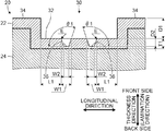
- FIG. 3 is a side sectional view showing a schematic configuration of a second concave portion.
- the cutting position corresponds to the line F-F shown in the lower row of FIG. 1 .
- the base material shows a part in a thickness direction.
- FIG. 4 is a side view showing an example of a schematic configuration of an emboss processing apparatus.
- An emboss processing mold and an emboss receiving mold have roll shapes.
- the base material and the decorative sheet show portions corresponding to the emboss processing apparatus.
- FIG. 5 is a partial perspective view showing an example of a schematic configuration of the emboss processing mold. A range of the emboss processing mold corresponding to a second reference region is shown.
- FIG. 6 is a side view showing an example of a schematic configuration of a third mold portion.
- FIG. 7 is a side view showing another example of a schematic configuration of an emboss processing apparatus.
- An emboss processing mold and an emboss receiving mold have flat plate shapes.
- the emboss processing mold is shown in a moved state to a first side in an arrangement direction with respect to the emboss receiving mold.
- a base material and a decorative sheet show portions corresponding to the emboss processing apparatus.
- Each drawing of the embodiment schematically shows predetermined configurations. Therefore, in each drawing of the embodiment, correspondence with another drawing or correspondence with a numerical value to be described later specifying the configuration in the drawing may not be accurate in some cases.
- hatching indicates a cross section.
- the decorative sheet 10 includes a base material 20 and a concavo-convex pattern 30 .
- the concavo-convex pattern 30 is provided on a front surface of the base material 20 .
- the decorative sheet 10 and the base material 20 are elongated sheet materials.
- the concavo-convex pattern 30 is formed on the front surface of the base material 20 by carrying out an emboss processing method by an emboss processing apparatus 50 .
- the emboss processing apparatus 50 and the emboss processing method will be described later.
- a longitudinal direction of the base material 20 is the longitudinal direction of the decorative sheet 10
- a transverse direction of the base material 20 is the transverse direction of the decorative sheet 10 .
- the longitudinal direction of the decorative sheet 10 and the base material 20 is simply referred to as “longitudinal direction”
- the transverse direction of the decorative sheet 10 and the base material 20 is simply referred to as “transverse direction” (see FIG. 1 ).
- the longitudinal direction and the transverse direction are orthogonal to each other.
- the base material 20 various sheet materials are adopted. For example, various sheet materials having different thicknesses are adopted as the base material 20 .
- the base material 20 is a laminate body having two or more layers.
- the decorative sheet 10 is also a laminated body which has the same number of laminations as the base material 20 .
- the base material 20 is a three-layer laminate body having a first sheet 22 , a second sheet 24 and a third sheet 26 (see the upper row of FIG. 1 ).
- the base material 20 has cushioning properties.
- the decorative sheet 10 is also a three-layer laminate body having cushioning properties (see the lower row of FIG. 1 ).
- the base material may be a laminate body of two layers or four or more layers.
- this base material may be a laminate body including the first sheet 22 and the second sheet 24 .
- the side on which the first sheet 22 is provided in a thickness direction, is referred to as “front side”.
- the side on which the third sheet 26 is provided is referred to as “back side”.
- the thickness direction coincides with the direction in which the first sheet 22 , the second sheet 24 and the third sheet 26 are laminated on the base material 20 .
- front surfaces are the surfaces which are on the front side in the thickness direction and back surfaces are the surfaces which are on the back side in the thickness direction.
- the front surface of the base material 20 becomes the front surface of the decorative sheet 10 and the back surface of the base material 20 becomes the back surface of the decorative sheet 10 . That is, in the state of the decorative sheet 10 , the front surface of the decorative sheet 10 and the front surface of the base material 20 means the same surface. Similarly, in the state of the decorative sheet 10 , the back surface of the decorative sheet 10 and the back surface of the base material 20 means the same surface.
- the decorative sheet 10 serves as an outer material of an interior article for a vehicle
- the front surface of the decorative sheet 10 will become the front surface of the aforementioned interior article.
- a user of the vehicle visually recognizes the front surface of the decorative sheet 10 forming the front surface of the interior article.
- a thickness T (see the upper row of FIG. 1 ) of the base material 20 is appropriately determined in consideration of various conditions. However, preferably, the thickness T of the base material 20 is set to a predetermined value in the range of 1.3 to 15.5 mm. As a result, a clear concavo-convex pattern 30 can be formed on the front surface of the base material 20 .
- the base material 20 is formed by bonding the first sheet 22 to the front surface of the second sheet 24 and bonding the third sheet 26 to the back surface of the second sheet 24 .
- Known methods are adopted for bonding the second sheet 24 and the first sheet 22 and bonding the second sheet 24 and the third sheet 26 . For example, the aforementioned bonding is performed via an adhesive.
- the aforementioned bonding is performed by frame lamination.
- frame lamination is preferable from the viewpoint of process load at the time of manufacturing the base material 20 and weight reduction of the base material 20 .
- Frame lamination is a technology already put into practical use. Therefore, explanation on frame lamination will be omitted.
- the first sheet 22 various sheet materials are adopted.
- a fibrous sheet material is adopted as the fibrous sheet material.
- a woven fabric, a knitted fabric, a nonwoven fabric or a natural leather is exemplified.
- Natural leather includes split leather.
- the following sheet material is adopted as the first sheet 22 .
- the aforementioned sheet material is a sheet material impregnated or laminated with a synthetic resin in a fibrous sheet material.
- artificial leather, synthetic leather or polyvinyl chloride leather is exemplified.
- a thickness T 1 (see the upper row of FIG. 1 ) of the first sheet 22 is preferably set to a predetermined value in the range of 0.3 to 1.5 mm.
- the thickness T 1 of the first sheet 22 is set to a predetermined value in the range of 0.5 to 1 mm.
- the thickness T 1 of the first sheet 22 may be different from the aforementioned range.
- the thickness T 1 of the first sheet 22 is appropriately determined in consideration of various conditions.
- the fibrous sheet material is preferably a sheet material made of a thermoplastic resin fiber as a material from the viewpoint of processability in emboss processing.
- a thermoplastic resin polyolefin resin, polyester resin, polyamide resin, vinyl chloride resin or polyvinylidene chloride is exemplified.
- polyolefin resin polyethylene or polypropylene is exemplified.
- polyester resin polyethylene terephthalate is exemplified.
- nylon 6 or nylon 66 is exemplified.
- the fibrous sheet material can be formed from one or more thermoplastic resin fibers selected from the group including the aforementioned plurality of resins.
- the first sheet 22 is a sheet material impregnated or laminated with a synthetic resin on a fibrous sheet material.
- a synthetic resin is adopted as the resin to be impregnated or laminated.
- the aforementioned synthetic resin polyurethane resin or vinyl chloride resin is exemplified.
- the fibrous sheet material may be colored with known dyes or pigments. Dyes or pigments are appropriately determined in consideration of various conditions.
- the second sheet 24 has cushioning properties. Therefore, the base material 20 has cushioning properties as described above.
- various sheet materials having cushioning properties are adopted.
- synthetic resin foam, nonwoven fabric, multilayer woven fabric or multilayer knitted fabric is exemplified.
- the inventor believes that synthetic resin foams are preferable among the aforementioned sheet materials having cushioning properties from the viewpoint of processability in emboss processing.
- polyurethane foam is preferable from the viewpoint of versatility.
- a thickness T 2 (see the upper row of FIG. 1 ) of the second sheet 24 is preferably set to a predetermined value in the range of 1 to 14 mm.
- the third sheet 26 various sheet materials are adopted.
- a woven fabric, a knitted fabric or a nonwoven fabric is adopted.
- basis weight of the sheet material is appropriately determined in consideration of various conditions.
- the basis weight of the woven or knitted fabric is preferably set to a predetermined value in the range of 10 to 80 g/m2.
- the basis weight of the nonwoven fabric is preferably set to a predetermined value in the range of 10 to 40 g/m2.
- the third sheet 26 is preferably a sheet material made of a thermoplastic resin fiber as a material from the viewpoint of processability in emboss processing.
- the thermoplastic resin serving as a material the above-described resin related to the first sheet 22 is exemplified.
- the concavo-convex pattern 30 includes a first concave portion 32 , a convex portion 34 and a second concave portion 36 (see the lower row of FIG. 1 and FIGS. 2 and 3 ).
- the first concave portion 32 is a bottomed concave portion (see the lower row of FIG. 1 and FIG. 3 ). Furthermore, the first concave portion 32 is a concave portion whose depth direction coincides with the thickness direction.
- the convex portion 34 is a convex portion which is adjacent to the first concave portion 32 and whose height direction coincides with the thickness direction.
- the second concave portion 36 is a bottomed concave portion (see FIG. 3 ).
- the second concave portion 36 is a concave portion which opens at the bottom surface of the first concave portion 32 and whose depth direction coincides with the thickness direction.
- the second concave portion 36 is provided in a first region R 1 of the bottom surface of the first concave portion 32 (see FIG. 2 ).
- the first region R 1 is a region of the bottom surface of the first concave portion 32 which is a region spaced apart from a boundary between the first concave portion 32 and the convex portion 34 not less than a maximum dimension W 1 .
- the maximum dimension W 1 is a maximum dimension in an opening direction of an opening end of the second concave portion 36 on the side of the bottom surface of the first concave portion 32 in the thickness direction (see FIG. 3 ).
- the opening direction is orthogonal to the thickness direction.
- the maximum dimension W 1 is the diameter of the circle.
- the maximum dimension W 1 is the major axis of the ellipse.
- the maximum dimension W 1 is the dimension of the diagonal line which becomes longer among the two diagonal lines.
- the relationship between a following distance L 1 and the maximum dimension W 1 is “distance L 1 ⁇ maximum dimension W 1 ”.
- the distance L 1 is a distance in the longitudinal direction from the boundary between the first concave portion 32 and the convex portion 34 to the second concave portion 36 (see FIG. 2 ).
- the concavo-convex pattern 30 is a concavo-convex pattern in which a plurality of first concave portions 32 and a plurality of convex portions 34 are alternately repeated in the longitudinal direction (see FIGS. 1 and 2 ).
- the first concave portion 32 has a rectangular shape in which the bottom surface traverses the base material 20 in the transverse direction.
- the convex portion 34 has a rectangular shape in which the top surface traverses the base material 20 in the transverse direction.
- the concavo-convex pattern 30 is a pattern in which a plurality of second concave portion rows are provided in the longitudinal direction.
- One second concave portion row is formed by arranging a plurality of second concave portions 36 in the transverse direction.
- the second concave portion row has two rows.
- the two second concave portion rows are provided so as to be adjacent to each other in the longitudinal direction in a state shifted by a predetermined amount in the transverse direction.
- the second concave portion 36 is a truncated cone-shaped concave portion which is as the following first aspect and second aspect.
- the opening end and the bottom surface are circular shapes.
- the bottom surface is parallel to the bottom surface of the first concave portion 32 .
- the following second concave portion is denoted by reference numeral “ 36 ”.
- the aforementioned second concave portion is one second concave portion among a plurality of second concave portions 36 provided on the bottom surface of one first concave portion 32 .
- the concavo-convex pattern 30 is an example.
- various concavo-convex patterns are adopted as the concavo-convex pattern 30 .
- the first concave portion 32 and the convex portion 34 and the second concave portion 36 may have shapes different from the above-described shapes.
- the first concave portion 32 may be a concave portion whose bottom surface is any one of, for example, a circular shape, an elliptical shape, a polygonal shape, a star shape and a flower shape.
- the convex portion 34 has a shape corresponding to the shape of the first concave portion 32 , and forms a space between the plurality of first concave portions 32 .
- the second concave portion 36 may be a concave portion in which the opening end and the bottom surface are any one of, for example, an elliptical shape, a polygonal shape, a star shape and a flower shape.
- the first concave portion 32 is preferably a concave portion having a third area of 25 mm2 or more in view of design properties of the concavo-convex pattern 30 .
- the third area is a sum of a first area and a second area.
- the first area is an area of the bottom surface of the first concave portion 32 excluding an opening region.
- the opening region is a region where the second concave portion 36 opens at the bottom surface of the first concave portion 32 (the opening end of the second concave portion 36 ).
- the second area is an area of the opening region.
- N second concave portions 36 are provided on the bottom surface of one first concave portion 32 .
- the area of the region where the second concave portion 36 opens at the bottom surface of the first concave portion 32 is assumed to be M.
- the second area is a product of N and M.
- Each of the first area, the second area and the third area considers the bottom surface of one first concave portion 32 .
- the first concave portion 32 is preferably an area ratio of 5 to 60% with respect to a first reference region RA.
- the aforementioned area ratio is based on the area of each range of the first concave portion 32 and the first reference region RA which can be visually recognized in the following state.
- the aforementioned state is a state in which the decorative sheet 10 is viewed from above in the thickness direction from the front side (see FIG. 2 ).
- the first reference region RA is a region formed by a pair of adjacent first concave portion 32 and convex portion 34 (see the lower row of FIG. 1 , and FIG. 2 ).
- the concavo-convex pattern 30 having a three-dimensional effect.
- the convex portion 34 having a height.
- the two first concave portions 32 adjacent to each other via the convex portion 34 is preferably spaced apart by about twice the thickness T of the base material 20 before emboss processing.
- the entrainment is a drawback in which the first sheet 22 is pulled toward the bottom surface of the first concave portion 32 at the following portion.
- the aforementioned portion is a portion of the first concave portion 32 continuing from the top surface of the convex portion 34 to the first concave portion 32 .
- Depth D 1 (see FIG. 3 ) of the first concave portion 32 is appropriately determined in consideration of various conditions. However, it is preferable that the first concave portion 32 is a concave portion whose depth D 1 is set to a predetermined value in the range of 1 to 15 mm. By setting the depth D 1 to 1 mm or more, the concavo-convex pattern 30 having a three-dimensional effect can be obtained. By setting the depth D 1 to 15 mm or less, it is possible to ensure good processability in the emboss processing method implementation. Productivity of the decorative sheet 10 can be enhanced.
- Depth D 2 (see FIG. 3 ) of the second concave portion 36 is preferably 50% or more and less than 100% with respect to the thickness T 1 of the first sheet 22 .
- the depth D 2 By setting the depth D 2 to 50% or more with respect to the thickness T 1 , the visibility of the second concave portion 36 can be improved. The viewer of the decorative sheet 10 can visually recognize the second concave portion 36 .
- the depth D 2 By setting the depth D 2 to less than 100% with respect to the thickness T 1 , the bottom surface of the second concave portion 36 can be included in the first sheet 22 .
- the concavo-convex pattern 30 having preferable design properties can be obtained.
- the second concave portion 36 is preferably a concave portion whose maximum dimension W 1 is set to a predetermined value in the range of 0.5 to 2 mm.
- the maximum dimension W 1 is set to 0.5 mm or more, the visibility of the second concave portion 36 can be improved.
- the viewer of the decorative sheet 10 can visually recognize the second concave portion 36 .
- the maximum dimension W 1 is set to 2 mm or less, the degree of freedom of the following point can be increased. As a result, it is possible to obtain the concavo-convex pattern 30 having preferable design properties.
- the aforementioned point is the point of arrangement of the second concave portion 36 with respect to the bottom surface of the first concave portion 32 .
- the second concave portion 36 may be a concave portion in which the opening area of the opening end is set to a predetermined value in the range of 0.19 to 3.2 mm2.
- the second concave 36 is preferably provided in the first region R 1 in a state in which the ratio of the second area to the third area is 5% or more and 35% or less.
- the ratio of the second area to the third area is 5% or more and 35% or less.
- the second concave portion 36 is preferably a concave portion in which an angle ⁇ 1 is set to a predetermined value in the range of 90 to 120°.
- the angle ⁇ 1 is an angle between a wall surface of the second concave portion 36 and the bottom surface of the second concave portion 36 (see FIG. 3 ).
- a corner portion E at the opening end of the second concave portion 36 can have a sharp shape.
- the second concave portion 36 can be made to look like a through hole.
- the following impression can be given to the viewer of the decorative sheet 10 .
- the aforementioned impression is an impression that the following portion is a pattern including a plurality of through holes.
- the aforementioned portion is the bottom surface of the first concave portion 32 provided with the plurality of second concave portions 36 .
- the second concave portion 36 is preferably a concave portion in which the ratio of a maximum dimension W 2 to the maximum dimension W 1 is set to a predetermined value in the range of 30 to 80%.
- the maximum dimension W 2 is a maximum dimension of the bottom surface of the second concave portion 36 in the opening direction (see FIG. 3 ).
- the maximum dimension W 2 is the diameter of the circle.
- the maximum dimension W 2 is the major diameter of the ellipse.
- the maximum dimension W 2 is the dimension of the diagonal which becomes longer among the two diagonal lines.
- the corner portion E at the opening end of the second concave portion 36 can have a sharp shape.
- the second concave portion 36 can be made to look like a through hole.
- the following impression can be given to the viewer of the decorative sheet 10 .
- the aforementioned impression is an impression that the following portion is a pattern including a plurality of through holes.
- the aforementioned portion is the bottom surface of the first concave portion 32 provided with the plurality of second concave portions 36 .
- the emboss processing apparatus 50 will be described with reference to FIGS. 4 and 5 .
- the emboss processing apparatus 50 is a processing apparatus for manufacturing the decorative sheet 10 .
- the emboss processing apparatus 50 conveys the elongated base material 20 fed out from a supply device 95 and carries out emboss processing to the base material 20 (see FIG. 4 ).
- emboss processing is performed continuously.
- the base material 20 is recovered in a recovery device 96 as the decorative sheet 10 .
- each of the aforementioned parts is the base material 20 and the decorative sheet 10 , the supply device 95 and the recovery device 96 .
- the base material 20 and the decorative sheet 10 have an aspect of a continuous elongated sheet material from the supply device 95 to the recovery device 96 .
- As the supply device 95 a supply device provided in a known emboss processing apparatus can be adopted.
- As the recovery device 96 a recovery device provided in a known emboss processing apparatus can be adopted. Therefore, the descriptions of the supply device 95 and the recovery device 96 will be omitted.
- the direction in which the base material 20 and the decorative sheet 10 are conveyed from the supply device 95 to the recovery device 96 is referred to as a “conveying direction”.
- the conveying direction is a direction along the longitudinal direction.
- the emboss processing apparatus 50 includes an emboss processing mold 60 , an emboss receiving mold 80 , and heating portions 90 , 92 .
- the emboss processing mold 60 has a roll shape. In this case, the emboss processing mold 60 may be referred to as an emboss roll.
- the emboss receiving mold 80 has a roll shape. In this case, the emboss receiving mold 80 may be referred to as a receiving roll or a backup roll.
- the emboss processing mold 60 and the emboss receiving mold 80 are provided side by side in an arrangement direction.
- the emboss processing mold 60 is provided on a first side in the arrangement direction.
- the emboss receiving mold 80 is provided on a second side in the arrangement direction.
- the arrangement direction is the vertical direction and the conveying direction is the horizontal direction. Further, the first side in the arrangement direction is the upper side in the vertical direction and the second side in the arrangement direction is the lower side in the vertical direction. In this case, the thickness direction (lamination direction) of the base material 20 coincides with the vertical direction.
- the arrangement direction may be a direction different from the vertical direction.
- the conveying direction may be a direction different from the horizontal direction.
- the conveying direction is preferably a direction orthogonal to the arrangement direction.
- the emboss processing mold 60 rotates in a direction corresponding to the conveying direction with a shaft 62 as a rotation axis.
- the emboss processing mold 60 is imparted with a driving force from a driving portion.
- the driving portion is attached to the shaft 62 . Accordingly, as aforementioned, the emboss processing mold 60 rotates.
- FIG. 4 illustration of the driving portion is omitted.
- a motor is exemplified.
- the following arrow shown in FIG. 4 indicates a rotation direction of the emboss processing mold 60 .
- the aforementioned arrow is an arrow of a single arrow indicated inside the emboss processing mold 60 .
- the emboss processing mold 60 is formed of the same material as a known emboss processing mold.
- the emboss processing mold 60 is made of metal.
- a steel material is exemplified.
- the emboss processing mold 60 includes a molding portion 70 .
- the molding portion 70 has a concavo-convex shape corresponding to the concavo-convex pattern 30 .
- the molding portion 70 is in contact with the front surface of the base material 20 and presses the front surface of the base material 20 .
- the molding portion 70 includes a first mold portion 72 , a second mold portion 74 and a third mold portion 76 (see FIGS. 4 and 5 ).
- the first mold portion 72 is a convex portion corresponding to the first concave portion 32 of the molding portion 70 .
- the second mold portion 74 is a concave portion corresponding to the convex portion 34 of the molding portion 70 .
- the third mold portion 76 is a convex portion corresponding to the second concave portion 36 of the molding portion 70 .
- the third mold portion 76 is provided in a second region R 2 of a top surface of the first mold portion 72 (see FIG. 5 ).
- the second region R 2 is a region of the top surface of the first mold portion 72 which is a region spaced apart from the following portion not less than a maximum dimension W 3 .
- the aforementioned portion is an outer edge portion of the top surface of the first mold portion 72 . This outer edge portion is a position corresponding to the boundary between the first concave portion 32 and the convex portion 34 in the top surface of the first mold portion 72 .
- the maximum dimension W 3 is a maximum dimension in a following direction of a rear end of the third mold portion 76 (see FIGS. 5 and 6 ).
- the rear end of the third mold portion 76 is the end of the third mold portion 76 on the side of the top surface of the first mold portion 72 .
- the aforementioned direction is a direction along the top surface of the first mold portion 72 .
- the second concave portion 36 is a truncated cone-shaped concave portion as described above. Therefore, the rear end of the third mold portion 76 has a circular shape.
- the maximum dimension W 3 is the diameter of the circle.
- the maximum dimension W 3 is the major diameter of the ellipse.
- the maximum dimension W 3 is the dimension of the diagonal line which becomes longer among the two diagonal lines.
- the relationship between a following distance L 2 and the maximum dimension W 3 is “distance L 2 ⁇ maximum dimension W 3 ”.
- the distance L 2 is the shortest distance in the aforementioned direction from the outer edge portion of the top surface of the first mold portion 72 to the third mold portion 76 (see FIG. 5 ).
- the molding portion 70 includes a plurality of first mold portions 72 and a plurality of second mold portions 74 corresponding to the concavo-convex pattern 30 (see FIGS. 1 and 2 ) of the following aspect mentioned above (see FIG. 4 ).
- the aforementioned aspect is an aspect which the plurality of first concave portions 32 and the plurality of convex portions 34 are alternately repeated in the longitudinal direction. Therefore, in the molding portion 70 , the plurality of first mold portions 72 and the plurality of second mold portions 74 are alternately repeated in a circumferential direction.
- the circumferential direction coincides with the rotation direction of the emboss processing mold 60 and the opposite direction thereof (see FIGS. 4 and 5 ).
- the molding portion 70 includes a plurality of third mold portions 76 (see FIG. 5 ).
- the plurality of third mold portions 76 are provided at respective positions corresponding to the aforementioned arrangement of the plurality of second concave portions 36 in the second region R 2 .
- the following third mold portion is denoted by reference numeral “ 76 ”.
- the aforementioned third mold portion is one third mold portion among the plurality of third mold portions 76 corresponding to one first mold portion 72 .
- the first mold portion 72 is formed in a convex shape whose top surface is a rectangular shape corresponding to the bottom surface of the first concave portion 32 (see FIG. 5 ). Unlike this, it is assumed that the bottom surface of the first concave portion 32 is any one of the circular shape, the elliptical shape, the polygonal shape, the star shape and the flower shape exemplified above.
- the first mold portion 72 is formed in a convex shape whose top surface is any one of a circular shape, an elliptical shape, a polygonal shape, a star shape and a flower shape corresponding to the bottom surface of the first concave portion 32 .
- the first mold portion 72 is preferably a convex shape having an area of the top surface is 25 mm2 or more.
- the first concave portion 32 can be a concave portion having the third area of 25 mm2 or more. In the case of manufacturing the emboss processing mold 60 , the formation of the third mold portion 76 becomes easy.
- the first mold portion 72 is preferably 5 to 60% in area ratio with respect to a second reference region RB.
- the aforementioned area ratio corresponds to the area ratio of the first concave portion 32 with respect to the first reference region RA described above.
- the second reference region RB is a region formed by a pair of adjacent first mold portions 72 and second mold portions 74 (see FIG. 5 ). This makes it possible to set the first concave portion 32 to the area ratio of 5 to 60% with respect to the first reference region RA.
- the concavo-convex pattern 30 having a three-dimensional effect can be formed on the front surface of the base material 20 .
- the convex part 34 having a height.
- the concavo-convex pattern 30 having a three-dimensional effect can be formed on the front surface of the base material 20 .
- the first mold portion 72 has a convex shape in which the height H 1 is set to a predetermined value in the range of 1 to 15 mm.
- the concavo-convex pattern 30 having a three-dimensional effect can be formed on the front surface of the base material 20 .
- the height H 1 By setting the height H 1 to 15 mm or less, it is possible to ensure good processability in the emboss processing method implementation. It is possible to prevent the processing speed from being lowered. As a result, the productivity of the decorative sheet 10 can be enhanced.
- the third mold portion 76 is formed in a convex shape in which the rear end and a top surface are in a circular shape corresponding to the opening end and the bottom surface of the second concave portion 36 (see FIG. 5 ). Unlike this, it is assumed that the opening end and the bottom surface of the second concave portion 36 are any of the elliptical shape, the polygonal shape, the star shape and the flower shape exemplified above.
- the third mold portion 76 is formed in a convex shape in which the rear end and the top surface are any one of an elliptical shape, a polygonal shape, a star shape and a flower shape corresponding to the opening end and the bottom surface of the second concave portion 36 .
- Height H 2 (see FIG. 6 ) of the third mold portion 76 is preferably 50% or more and less than 100% with respect to the thickness T 1 of the first sheet 22 .
- the depth D 2 of the second concave portion 36 can be set to 50% or more and less than 100% with respect to the thickness T 1 of the first sheet 22 .
- the height H 2 By setting the height H 2 to 50% or more with respect to the thickness T 1 , it is possible to form the second concave portion 36 having a preferable visibility on the front surface of the base material 20 (the bottom surface of the first concave portion 32 ).
- the bottom surface of the second concave portion 36 can be included in the first sheet 22 .
- the third mold portion 76 has a convex shape in which the maximum dimension W 3 is set to a predetermined value in the range of 0.5 to 2 mm (see FIG. 6 ).
- the third mold portion 76 may have a convex shape in which an area of the rear end of the third mold portion 76 is set to a predetermined value in the range of 0.19 to 3.2 mm2.
- the third mold portion 76 is preferably provided in the second region R 2 in a state in which a ratio of a fifth area to a sixth area is 5% or more and 35% or less.
- the sixth area is a sum of a fourth area and the fifth area.
- the fourth area is an area of the top surface of the first mold portion 72 excluding a non-exposed region.
- the non-exposed region is a region which is not exposed by the third mold portion 76 on the top surface of the first mold portion 72 .
- the fifth area is an area of the non-exposed area. It is assumed that a number of N third mold portions 76 are provided on the top surface of one first mold portion 72 . For one third mold portion 76 , the area of the rear end of the third mold portion 76 is assumed to be M.
- the third mold portion 76 is preferably formed in a convex shape in which an angle ⁇ 2 is set to a predetermined value in the range of 90 to 120°.
- the angle ⁇ 2 is an angle between a side surface of the third mold portion 76 and the top surface of the third mold portion 76 (see FIG. 6 ).
- the second concave portion 36 can be a concave portion whose angle ⁇ 1 is set to a predetermined value in the range of 90 to 120°.
- the corner portion Eat the opening end of the second concave portion 36 can have a sharp shape.
- the second concave portion 36 can be made to look like a through hole.
- the third mold portion 76 is preferably formed in a convex shape in which a ratio of a maximum dimension W 4 to the maximum dimension W 3 is set to a predetermined value in the range of 30 to 80%.
- the maximum dimension W 4 is a maximum dimension of the top surface of the third mold portion 76 in the following direction (see FIG. 6 ).
- the aforementioned direction is a direction along the top surface of the first mold portion 72 , as like the maximum dimension W 3 .
- the second concave portion 36 is a truncated cone-shaped concave portion as described above, the top surface (tip end) of the third mold portion 76 has a circular shape. Therefore, the maximum dimension W 4 is the diameter of the circle.
- the second concave portion 36 when the second concave portion 36 is in the shape of an elliptical frustum, the maximum dimension W 4 is the major diameter of the ellipse.
- the maximum dimension W 4 is the dimension of the diagonal line which becomes longer among the two diagonal lines.
- the second concave portion 36 can be a concave portion in which the ratio of the maximum dimension W 2 to the maximum dimension W 1 is set to a predetermined value in the range of 30 to 80%.
- the corner portion E at the opening end of the second concave portion 36 can have a sharp shape.
- the second concave portion 36 can be made to look like a through hole.
- the emboss receiving mold 80 rotates in a direction corresponding to the conveying direction with a shaft 82 as a rotation axis.
- the rotation direction of the emboss receiving mold 80 is opposite to the rotation direction of the emboss processing mold 60 .
- the emboss receiving mold 80 is in contact with the back surface of the base material 20 .
- the emboss processing mold 60 and the emboss receiving mold 80 sandwich the base material 20 .
- the emboss receiving mold 80 rotates following the rotation of the emboss processing mold 60 in a state of being in contact with the back surface of the base material 20 .
- the following arrow shown in FIG. 4 shows a rotation direction of the emboss receiving mold 80 .
- the aforementioned arrow is an arrow of a single arrow indicated inside the emboss receiving mold 80 .
- the emboss receiving mold 80 an emboss receiving mold provided in a known emboss processing apparatus can be adopted. Therefore, other explanation on the emboss receiving mold 80 will be omitted.
- the heating portion 90 is embedded in the emboss processing mold 60 .
- the heating portion 90 heats the emboss processing mold 60 to a predetermined temperature.
- the heating portion 92 is embedded in the emboss receiving mold 80 .
- the heating portion 92 heats the emboss receiving mold 80 to a predetermined temperature.
- the heating portions 90 , 92 are electric heaters. In the embodiment, with respect to the emboss processing mold 60 , four heating portions 90 formed by electric heaters are embedded therein at equiangular intervals and with respect to the emboss receiving mold 80 , four heating portions 92 formed by electric heaters are embedded therein at equiangular intervals. However, the heating portions 90 , 92 may be heating portions of a different type from that of the electric heater.
- the number of the heating portions 90 with respect to the emboss processing mold 60 may be three or less, or five or more.
- the number of the heating portions 92 with respect to the emboss receiving mold 80 may be three or less, or five or more.
- the type and number of the heating portions 90 , 92 are appropriately determined in consideration of various conditions.
- the arrangement of the heating portions 90 in the emboss processing mold 60 is appropriately determined in consideration of various conditions.
- the arrangement of the heating portions 92 in the emboss receiving mold 80 is appropriately determined in consideration of various conditions.
- the temperature of the emboss processing mold 60 heated by the heating portions 90 is appropriately set according to the type of the base material 20 .
- the aforementioned temperature is appropriately set in consideration of the material of either or both of the first sheet 22 and the second sheet 24 .
- the first sheet 22 is polyethylene terephthalate.
- the melting point of polyethylene terephthalate is 260° C.
- the heating portions 90 heat the emboss processing mold 60 to a predetermined value in the range of 60 to 210° C.
- the heating portions 90 heat the emboss processing mold 60 to a predetermined value in the range of 80 to 180° C.
- a clear concavo-convex pattern 30 can be formed on the front surface of the base material 20 .
- the front surface quality of the first sheet 22 can be made preferable. As a result, the decorative sheet 10 with good texture can be obtained.
- the emboss processing method will be described with reference to FIGS. 1 and 4 .
- the emboss processing method is performed by the emboss processing apparatus 50 .
- the emboss processing method includes a supplying process, an embossing process and a recovering process (see FIG. 4 ).
- the emboss processing method By the emboss processing method, the decorative sheet 10 shown in the lower row of FIG. 1 is manufactured from the base material 20 shown in the upper row of FIG. 1 . Therefore, the emboss processing method can be said to be a manufacturing method of the decorative sheet 10 .
- the emboss processing method while continuously conveying the base material 20 in the conveying direction, the supplying process, the embossing process and the recovering process are successively carried out.
- the supplying process is carried out continuously with respect to the continuously conveyed base material 20 .
- the embossing process is carried out continuously with respect to the continuously conveyed base material 20 .
- the recovering process is carried out continuously with respect to the continuously conveyed base material 20 .
- the emboss processing apparatus 50 when the emboss processing method is carried out, the driving portion for the emboss processing mold 60 is continuously driven.
- the concavo-convex pattern 30 is formed on the front surface of the base material 20 (see FIG. 1 ).
- the heating portion 90 heats the emboss processing mold 60 .
- the heating portion 92 heats the emboss receiving mold 80 .
- the emboss processing method is carried out in a state in which the emboss processing mold 60 is heated to the above-described predetermined temperature and the emboss receiving mold 80 is heated to a predetermined temperature.
- the temperature of the emboss receiving mold 80 is appropriately set in consideration of various conditions.
- the heating portion 92 may be omitted.
- the emboss processing method is carried out in a state in which the emboss receiving mold 80 is not directly heated.
- the supplying process is a process of supplying the base material 20 to the emboss processing apparatus 50 (see FIG. 4 ). That is, in the supplying process, the base material 20 is fed out from the supplying device 95 . The base material 20 fed out from the supplying device 95 is conveyed in the conveying direction and reaches the emboss processing apparatus 50 .
- the embossing process is a process of forming the concavo-convex pattern 30 on the front surface of the base material 20 (see FIG. 4 ).
- emboss processing is applied to the base material 20 that has reached the emboss processing apparatus 50 .
- the embossing process includes a first concave portion process, a convex portion process, and a second concave portion process.
- the first concave portion process is a process of forming the first concave portions 32 .
- the convex portion process is a process of forming the convex portions 34 .
- the second concave portion process is a process of forming the second concave portions 36 .
- the second concave portions 36 are formed in the first regions R 1 of the bottom surfaces of the first concave portions 32 .
- the second concave portion process is carried out together with the first concave portion process. That is, the base material 20 conveyed in the conveying direction passes between the emboss processing mold 60 and the emboss receiving mold 80 during conveyance. At this time, the base material 20 is in contact with the outer surface of the emboss receiving mold 80 on the back surface and is supported by the emboss receiving mold 80 from the back side. The base material 20 is brought into contact with the molding portion 70 on the front surface and is pressed by the molding portion 70 .
- the base material 20 is heated by the heat from the emboss processing mold 60 heated by the heating portion 90 .
- the base material 20 is formed into the decorative sheet 10 (see FIG. 1 ).
- the base material 20 is in contact with the second mold portions 74 during the embossing process.
- the base material 20 may not contact the second mold portions 74 in some cases.
- the recovering process is a process of recovering the base material 20 that has passed through the emboss processing apparatus 50 (see FIG. 4 ). That is, in the recovering process, the decorative sheet 10 is recovered from the emboss processing apparatus 50 by the recovering device 96 .
- the back surface has a concavo-convex shape corresponding to the first concave portion 32 and the convex portion 34 on the front surface.
- a back surface of a decorative sheet may not have a concavo-convex shape corresponding to a concavo-convex pattern of a front surface.
- the aforementioned case is case where the emboss processing method is performed in the emboss processing apparatus 50 in the same manner as above.
- the back surface of the decorative sheet becomes concavo-convex shaped (see the lower row of FIG. 1 ) or flat shaped (not shown), it is determined by the characteristics of the base material 20 .
- the characteristics of the base material 20 means the characteristics of some or all of the characteristics of the respective materials of the first sheet 22 , the second sheet 24 and the third sheet 26 .
- the decorative sheet may not have the concavo-convex shape on the back surface.
- the aforementioned characteristics are the characteristics that it is difficult to stretch and that thermal shrinkage is large.
- the point that the back surface of the base material 20 is deformed into a concavo-convex shape is a known event.
- the aforementioned point is described in Japanese Patent No. 5913755 described above.
- a conveying speed of the base material 20 is preferably set to a predetermined value in the range of 0.1 to 10 m/min.
- the conveying speed of the base material 20 is set to a predetermined value in the range of 0.3 to 5 m/min.
- a pressing time of the base material 20 is preferably set to a predetermined value in the range of 0.01 to 5 seconds.
- the pressing time of the base material 20 is set to a predetermined value in the range of 0.1 to 2 seconds.
- the pressing force to the base material 20 is preferably set to a predetermined value in the range of 0.7 to 7 kgf/cm2.
- the pressing force to the base material 20 is set to a predetermined value in the range of 1.4 to 3.5 kgf/cm2.
- the inventor conducted experiments to confirm the effectiveness of the emboss process method and the emboss processing mold 60 of the emboss processing apparatus 50 of the embodiment.
- the experimental results obtained by the experiments will be described below.
- the reference numerals for each part are the same as above.
- the emboss processing apparatus 50 is referred to as “emboss processing apparatuses 51 , 52 , 53 ”.
- Samples 1, 2, and 3 were evaluated.
- Sample 1 was produced by the emboss processing apparatus 51 .
- Sample 2 was produced by the emboss processing apparatus 52 .
- Sample 3 was produced by the emboss processing apparatus 53 .
- Samples 1, 2, and 3 correspond to the decorative sheet 10 .
- the concavo-convex pattern 30 was a concavo-convex pattern (stripe pattern) in which a plurality of first concave portions 32 and a plurality of convex portions 34 were alternately repeated in the longitudinal direction (see the lower row of FIG. 1 ).
- the same base material 20 was used.
- the base material 20 was a three-layer laminate body (see the upper row of FIG. 1 ).
- the configurations of the first sheet 22 , the second sheet 24 and the third sheet 26 were as follows.
- the first sheet 22 , the second sheet 24 and the third sheet 26 were laminated by frame laminating.
- First sheet 22 (material, thickness T 1 ): Synthetic leather (laminate polyurethane resin layer on tricot knitted fabric), 1 mm
- Second sheet 24 (material, thickness T 2 ): Flexible polyurethane foam sheet (INOAC CORPORATION, trade name of product: EL67), 5 mm
- Third sheet 26 (material, basis weight): Nonwoven fabric (polyester nonwoven fabric), 40 g/m2
- the emboss processing apparatuses 51 , 52 , 53 are emboss processing apparatuses corresponding to the emboss processing apparatus 50 .
- the difference between the emboss processing apparatuses 51 , 52 , 53 is the emboss processing mold 60 .
- the emboss processing mold 60 and the emboss receiving mold 80 both have roll shapes (see FIG. 4 ).
- the specifications of the emboss processing molds 60 of the emboss processing apparatuses 51 , 52 , 53 and the processing conditions of the emboss processing method at the time of producing the Samples 1, 2, 3 are as follows: regarding the specification of the emboss processing mold 60 , the emboss processing apparatus 51 is used as a reference. In this case, the point that the emboss processing molds 60 of the emboss processing apparatuses 52 , 53 are different from the emboss processing mold 60 of the emboss processing apparatus 51 is the “specification of the third mold portion 76 ”.
- each shape of the first mold portion 72 and the third mold portion 76 correspond to the shapes when the following first mold portions 72 and the following third mold portions 76 shown in FIG. 4 are respectively viewed from directly in front of the drawing in a state in which the viewing direction is “Z 2 direction” shown in FIG. 4 .
- the aforementioned first mold portion 72 is the first mold portion 72 shown in FIG. 4 in a state of biting into the base material 20 on the second side in the arrangement direction.
- the aforementioned third mold portions 76 are each third mold portion 76 shown on the top surface of the aforementioned first mold portion 72 .
- a width direction coincides with the direction of the axis of the shaft 62 .
- the width direction is a direction perpendicular to the paper showing FIG. 4 and coincides with the transvers direction of the base material 20 .
- the concavo-convex pattern 30 formed on the front surface of the base material 20 was as follows.
- Each shape of the first concave portion 32 and the second concave portion 36 correspond to the shapes when the first concave portion 32 and the second concave portion 36 to be evaluated are respectively viewed from directly in front in a state in which the viewing direction is “Z 1 direction” shown in the lower row of FIG. 1 .
- Condition 1 the corner portions E of the second concave portions 36 are good and sharp
- the second concave portions 36 look like through holes, and it can be visually recognized that a pattern in which a plurality of through holes are arranged on the bottom surfaces of the first concave portions 32 is provided
- the decorative sheet 10 includes the base material 20 and the concavo-convex pattern 30 (see the lower row of FIG. 1 ).
- the concavo-convex pattern 30 is provided on the front surface of the base material 20 .
- the base material 20 includes the first sheet 22 and the second sheet 24 and further includes the third sheet 26 .
- the first sheet 22 , the second sheet 24 and the third sheet 26 are laminated.
- the concavo-convex pattern 30 includes the first concave portions 32 , the convex portions 34 and the second concave portions 36 .
- the second concave portion 36 are provided in the first regions R 1 of the bottom surfaces of the first concave portions 32 (see FIG. 2 ).
- the visibility of the second concave portions 36 provided on the bottom surfaces of the first concave portions 32 can be improved.
- the viewer of the decorative sheet 10 can visually recognize the second concave portions 36 from the obliquely upper side of the front side of the decorative sheet 10 .
- all of the plurality of second concave portions 36 provided on the bottom surfaces of all of the first concave portions 32 can be visually recognized.
- the second concave portions 36 are provided on the first sheet 22 in a state that the bottom surface is included in the first sheet 22 (see FIG. 3 ). Therefore, the second sheet 24 can be covered with the first sheet 22 . The second sheet 24 cannot be visually recognized from the front side of the decorative sheet 10 . Exposure of the second sheet 24 on the front surface of the decorative sheet 10 can be prevented.
- the embodiment can also be configured as follows. Some configurations of modifications illustrated below may also be employed in combination as appropriate. In the following description, points different from the above description are described, and the description of similar points is omitted as appropriate.
- the concavo-convex pattern 30 includes a plurality of second concave portions 36 on the bottom surface of the first concave portion 32 (see the lower row of FIG. 1 and FIG. 2 ).
- the concavo-convex pattern may be a pattern in which the number of the second concave portion with respect to one first concave portion is one.
- one third mold portion is provided on the top surface of the first mold portion.
- the opening region at the bottom surface of the first concave portion is equivalent to one second concave portion.
- the second area is an area of the region where one second concave portion opens at the bottom surface of the first concave portion.
- the non-exposed region on the top surface of the first mold portion is equivalent to one third mold portion.
- the fifth area is an area of the non-exposed region by one third mold portion on the top surface of the first mold portion.
- the emboss processing mold 60 and the emboss receiving mold 80 have roll shapes and are rotatably supported in a direction corresponding to the conveying direction (see FIG. 4 ).
- the emboss processing mold and the emboss receiving mold may have shapes different from the roll shape.
- an emboss processing mold 60 and an emboss receiving mold 80 may have flat plate shapes.
- the reference numerals with respect to each part are the same as those described above.
- the emboss processing mold 60 relatively reciprocates with respect to the emboss receiving mold 80 .
- this relative reciprocating movement a movement from a first side to a second side in an arrangement direction and a movement from the second side to the first side in the arrangement direction are repeated.
- a base material 20 is intermittently conveyed in a conveying direction in a state in which the emboss processing mold 60 has moved to the first side in the arrangement direction with respect to the emboss receiving mold 80 .
- An amount of conveyance per time is set to an amount that is a multiple number of an installation number of a dimension of a second reference region RB in a longitudinal direction.
- the installation number corresponds to a number of first mold portions 72 provided in a molding portion 70 .
- the emboss processing mold 60 is provided with two first mold portions 72 .
- the installation number is “2”. Therefore, the amount of conveyance at one time is twice the dimension of the second reference region RB in the longitudinal direction.
- a conveying speed of the base material 20 is preferably set to a predetermined value in the range of 0.5 to 6 m/min.
- the conveying speed of the base material 20 is set to a predetermined value in the range of 0.6 to 3 m/min.
- the emboss processing mold 60 is provided with heating portions 90 .
- the emboss receiving mold 80 is provided with heating portions 92 .
- the heating portions 90 heat the emboss processing mold 60 and the heating portions 92 heat the emboss receiving mold 80 .
- the heating portions 92 may be omitted.
- the base material 20 is sandwiched between the emboss processing mold 60 and the emboss receiving mold 80 .
- the base material 20 is in contact with an outer surface of the emboss receiving mold 80 on a back surface and is supported by the emboss receiving mold 80 from a back side.
- the base material 20 is brought into contact with the molding portion 70 on a front surface and is pressed by the molding portion 70 .
- the first mold portions 72 and third mold portions 76 of the molding portion 70 bite into the base material 20 .
- a concavo-convex pattern 30 is formed on the front surface of the base material 20 in the same manner as described above.
- a pressing time of the base material 20 is preferably set to a predetermined value in the range of 30 to 120 seconds.
- the pressing time of the base material 20 is set to a predetermined value in the range of 50 to 90 seconds. The same effect as described above can be obtained.
- the relative movement between the emboss processing mold 60 and the emboss receiving mold 80 preferably carried out such that the emboss processing mold 60 is reciprocated in the arrangement direction with the position of the emboss receiving mold 80 being fixed (see FIG. 7 ).
- relative movement between the emboss processing mold 60 and the emboss receiving mold 80 may be different from this aspect.
- the relative movement between the emboss processing mold 60 and the emboss receiving mold 80 may be carried out by reciprocating the emboss processing mold 60 and the emboss receiving mold 80 respectively in the arrangement direction.
- the emboss processing mold and the emboss receiving mold may be, for example, as follows. That is, the emboss processing apparatus may be provided with the roll-shaped emboss processing mold 60 shown in FIG. 4 and the flat-plate-shaped emboss receiving mold 80 shown in FIG. 7 .
- the base material 20 which is a three-layer laminate body was exemplified (see the upper row of FIG. 1 ). Further, it was explained that a two-layer laminate body or a laminate body of four or more layers can be adopted as the base material.
- the base material may be a single layer sheet material which is not a laminate body. That is, the base material may be a thick sheet material having cushioning properties.
Landscapes
- Engineering & Computer Science (AREA)
- Mechanical Engineering (AREA)
- Textile Engineering (AREA)
- Ceramic Engineering (AREA)
- Laminated Bodies (AREA)
- Shaping Of Tube Ends By Bending Or Straightening (AREA)
- Seats For Vehicles (AREA)
- Finishing Walls (AREA)
Abstract
Description
- Shape: Rectangular
- Dimensions (top surface, height H1): 9 mm×1500 mm (circumferential direction×width direction), 10 mm
- Area of the top surface (sixth area): 13500 mm2
- Ratio of the
first mold portion 72 to the second reference region RB: 25%
Specification ofThird Mold Portion 76 - Shape: Circular
- Dimensions (maximum dimensions W3, W4, height H2): 1 mm, 0.5 mm, 0.7 mm
- Angle θ2: 104°
- Ratio of the maximum dimension W4 to the maximum dimension W3: 50%
- Ratio of the fifth area to the sixth area: 32%
- Shape: Circular
- Dimensions (maximum dimensions W3, W4, height H2): 1 mm, 0.1 mm, 0.7 mm
- Angle θ2: 114°
- Ratio of the maximum dimension W4 to the maximum dimension W3: 10%
- Ratio of the fifth area to the sixth area: 32%
- Shape: Circular
- Dimensions (maximum dimensions W3, W4, height H2): 1 mm, 1 mm, 0.7 mm
- Angle θ2: 90°
- Ratio of the maximum dimension W4 to the maximum dimension W3: 100%
- Ratio of the fifth area to the sixth area: 32%
- Surface temperature of the emboss processing mold 60: 180° C.
- Surface temperature of the emboss receiving mold 80: 230° C.
- Conveying speed: 2 m/min
- Pressing force: 1.4 kgf/cm2
- Shape: Rectangular
- Dimensions (bottom surface, depth D1): 9 mm×1500 mm (longitudinal direction×transverse direction), 10 mm
- Area of the bottom surface (third area): 13500 mm2
- Ratio of the first
concave portion 32 to the first reference region RA: 25%
- Shape: Circular
- Dimensions (maximum dimension W1, W2, depth D2): 1 mm, 0.5 mm, 0.7 mm
- Angle θ1: 104°
- Ratio of the maximum dimension W2 to the maximum dimension W1: 50%
- Ratio of the second area to the third area: 32%
- Shape: Rectangular
- Dimensions (bottom surface, depth D1): 9 mm×1500 mm (longitudinal direction×transverse direction), 10 mm
- Area of the bottom surface (third area): 13500 mm2
- Ratio of the first
concave portion 32 to the first reference region RA: 25%
- Shape: Circular
- Dimensions (maximum dimension W1, W2, depth D2): 1 mm, 0.1 mm, 0.7 mm
- Angle θ1: 114°
- Ratio of the maximum dimension W2 to the maximum dimension W1: 10%
- Ratio of the second area to the third area: 32%
- Shape: Rectangular
- Dimensions (bottom surface, depth D1): 9 mm×1500 mm (longitudinal direction×transverse direction), 10 mm
- Area of the bottom surface (third area): 13500 mm2
- Ratio of the first
concave portion 32 to the first reference region RA: 25%
- Shape: Circular
- Dimensions (maximum dimension W1, W2, depth D2): 1 mm, 1 mm, 0.7 mm
- Angle θ1: 90°
- Ratio of the maximum dimension W2 to the maximum dimension W1: 100%
- Ratio of the second area to the third area: 32%
Claims (12)
Applications Claiming Priority (3)
| Application Number | Priority Date | Filing Date | Title |
|---|---|---|---|
| JP2017-203003 | 2017-10-19 | ||
| JPJP2017-203003 | 2017-10-19 | ||
| JP2017203003A JP7002280B2 (en) | 2017-10-19 | 2017-10-19 | Decorative sheet, embossing method and embossing type |
Publications (2)
| Publication Number | Publication Date |
|---|---|
| US20190118505A1 US20190118505A1 (en) | 2019-04-25 |
| US11046041B2 true US11046041B2 (en) | 2021-06-29 |
Family
ID=66170950
Family Applications (1)
| Application Number | Title | Priority Date | Filing Date |
|---|---|---|---|
| US16/164,218 Active 2038-12-25 US11046041B2 (en) | 2017-10-19 | 2018-10-18 | Decorative sheet, emboss processing method and emboss processing mold |
Country Status (3)
| Country | Link |
|---|---|
| US (1) | US11046041B2 (en) |
| JP (1) | JP7002280B2 (en) |
| CN (1) | CN109677084A (en) |
Families Citing this family (4)
| Publication number | Priority date | Publication date | Assignee | Title |
|---|---|---|---|---|
| JP7272081B2 (en) | 2019-04-17 | 2023-05-12 | トヨタ紡織株式会社 | Skin material manufacturing method |
| JP6815680B1 (en) * | 2020-08-31 | 2021-01-20 | スミノエ テイジン テクノ株式会社 | Vehicle interior materials, vehicle interior material manufacturing methods, and embossed rolls |
| JP7121242B2 (en) * | 2020-12-08 | 2022-08-18 | スミノエ テイジン テクノ株式会社 | Vehicle interior material and manufacturing method thereof |
| JP7403838B2 (en) | 2021-05-19 | 2023-12-25 | スミノエ テイジン テクノ株式会社 | Seat skin material, method for manufacturing seat skin material, and embossing device used for manufacturing seat skin material |
Citations (10)
| Publication number | Priority date | Publication date | Assignee | Title |
|---|---|---|---|---|
| US3629035A (en) * | 1966-12-19 | 1971-12-21 | Minoru Kuroda | Method of forming applique designs |
| US4393116A (en) * | 1979-07-24 | 1983-07-12 | Fastbac Research Limited | Shaped materials |
| US4561917A (en) * | 1984-07-05 | 1985-12-31 | Tachikawa Spring Co., Ltd. | Method of making a cushion body of synthetic resin |
| US20040185247A1 (en) * | 2003-03-21 | 2004-09-23 | Fenton Timm J. | Shoulder strap pad |
| JP2005261581A (en) | 2004-03-17 | 2005-09-29 | Achilles Corp | Sheet material for seat |
| JP2007276285A (en) | 2006-04-07 | 2007-10-25 | Suminoe Textile Co Ltd | Skin material for seat of vehicle having uneven pattern and method for manufacturing the same |
| US20090267401A1 (en) * | 2006-03-31 | 2009-10-29 | Mika Ito | Cushion body, seat, and method of manufacturing the same |
| US20140052041A1 (en) * | 2012-08-20 | 2014-02-20 | Alessandro Barberio | Medical protruded pads or dressings for wound care including use with orthopedic and prosthetic devices |
| JP5913755B1 (en) | 2014-11-18 | 2016-05-11 | 住江織物株式会社 | Seat skin material, manufacturing method of seat skin material, and embossing roll |
| JP1561835S (en) | 2015-10-27 | 2016-10-31 |
Family Cites Families (4)
| Publication number | Priority date | Publication date | Assignee | Title |
|---|---|---|---|---|
| US587930A (en) * | 1897-08-10 | Indicator for lathes or planers | ||
| US5897930A (en) * | 1996-12-31 | 1999-04-27 | Minnesota Mining And Manufacturing Company | Multiple embossed webs |
| WO2014181389A1 (en) * | 2013-05-07 | 2014-11-13 | Yamada Kikuo | Water-disintegrable paper manufacturing method |
| JP2016196102A (en) * | 2015-04-02 | 2016-11-24 | 共和レザー株式会社 | Synthetic resin skin material and method for producing the same |
-
2017
- 2017-10-19 JP JP2017203003A patent/JP7002280B2/en active Active
-
2018
- 2018-10-18 US US16/164,218 patent/US11046041B2/en active Active
- 2018-10-18 CN CN201811217547.1A patent/CN109677084A/en active Pending
Patent Citations (11)
| Publication number | Priority date | Publication date | Assignee | Title |
|---|---|---|---|---|
| US3629035A (en) * | 1966-12-19 | 1971-12-21 | Minoru Kuroda | Method of forming applique designs |
| US4393116A (en) * | 1979-07-24 | 1983-07-12 | Fastbac Research Limited | Shaped materials |
| US4561917A (en) * | 1984-07-05 | 1985-12-31 | Tachikawa Spring Co., Ltd. | Method of making a cushion body of synthetic resin |
| US20040185247A1 (en) * | 2003-03-21 | 2004-09-23 | Fenton Timm J. | Shoulder strap pad |
| JP2005261581A (en) | 2004-03-17 | 2005-09-29 | Achilles Corp | Sheet material for seat |
| US20090267401A1 (en) * | 2006-03-31 | 2009-10-29 | Mika Ito | Cushion body, seat, and method of manufacturing the same |
| JP2007276285A (en) | 2006-04-07 | 2007-10-25 | Suminoe Textile Co Ltd | Skin material for seat of vehicle having uneven pattern and method for manufacturing the same |
| US20140052041A1 (en) * | 2012-08-20 | 2014-02-20 | Alessandro Barberio | Medical protruded pads or dressings for wound care including use with orthopedic and prosthetic devices |
| JP5913755B1 (en) | 2014-11-18 | 2016-05-11 | 住江織物株式会社 | Seat skin material, manufacturing method of seat skin material, and embossing roll |
| US20170334127A1 (en) | 2014-11-18 | 2017-11-23 | Suminoe Textile Co., Ltd. | Seat covering material, method for manufacturing the seat covering material, and embossing roll |
| JP1561835S (en) | 2015-10-27 | 2016-10-31 |
Also Published As
| Publication number | Publication date |
|---|---|
| US20190118505A1 (en) | 2019-04-25 |
| CN109677084A (en) | 2019-04-26 |
| JP7002280B2 (en) | 2022-01-20 |
| JP2019077040A (en) | 2019-05-23 |
Similar Documents
| Publication | Publication Date | Title |
|---|---|---|
| US11046041B2 (en) | Decorative sheet, emboss processing method and emboss processing mold | |
| EP3524429B1 (en) | Method for manufacturing a floor covering product | |
| US11987023B2 (en) | Method for producing a composite material and composite material | |
| JP2019077040A5 (en) | ||
| US20200316846A1 (en) | Embossing Apparatus | |
| JP6629310B2 (en) | Dimensional improvement of artificial leather polyurethane composite | |
| JP5447902B1 (en) | Method for producing laminated sheet material and laminated sheet material | |
| JP7360805B2 (en) | Laminated foam sheet and method for manufacturing the same | |
| US11884048B2 (en) | Decorative sheet, embossing method and embossing die | |
| US11254246B2 (en) | Decorative sheet | |
| JP7107941B2 (en) | Embossing device and embossing method | |
| US11529759B2 (en) | Decorative sheet, embossing method and embossing die | |
| US11458670B2 (en) | Embossing die, embossing apparatus and embossing method | |
| JP2016128217A (en) | Decorative sheet, method for production thereof, and production method for tatami | |
| JP2022180015A (en) | Skin material |
Legal Events
| Date | Code | Title | Description |
|---|---|---|---|
| FEPP | Fee payment procedure |
Free format text: ENTITY STATUS SET TO UNDISCOUNTED (ORIGINAL EVENT CODE: BIG.); ENTITY STATUS OF PATENT OWNER: LARGE ENTITY |
|
| AS | Assignment |
Owner name: SEIREN CO., LTD., JAPAN Free format text: ASSIGNMENT OF ASSIGNORS INTEREST;ASSIGNOR:SHIRASAKI, TATSUYA;REEL/FRAME:047235/0652 Effective date: 20181011 |
|
| STPP | Information on status: patent application and granting procedure in general |
Free format text: DOCKETED NEW CASE - READY FOR EXAMINATION |
|
| STPP | Information on status: patent application and granting procedure in general |
Free format text: NON FINAL ACTION MAILED |
|
| STPP | Information on status: patent application and granting procedure in general |
Free format text: RESPONSE TO NON-FINAL OFFICE ACTION ENTERED AND FORWARDED TO EXAMINER |
|
| STPP | Information on status: patent application and granting procedure in general |
Free format text: FINAL REJECTION MAILED |
|
| STPP | Information on status: patent application and granting procedure in general |
Free format text: ADVISORY ACTION MAILED |
|
| STPP | Information on status: patent application and granting procedure in general |
Free format text: DOCKETED NEW CASE - READY FOR EXAMINATION |
|
| STPP | Information on status: patent application and granting procedure in general |
Free format text: NOTICE OF ALLOWANCE MAILED -- APPLICATION RECEIVED IN OFFICE OF PUBLICATIONS |
|
| STPP | Information on status: patent application and granting procedure in general |
Free format text: PUBLICATIONS -- ISSUE FEE PAYMENT RECEIVED |
|
| STPP | Information on status: patent application and granting procedure in general |
Free format text: PUBLICATIONS -- ISSUE FEE PAYMENT VERIFIED |
|
| STCF | Information on status: patent grant |
Free format text: PATENTED CASE |