US11026147B2 - Dynamic adaptation of maximum packet loss rate (PLR) for single radio voice call continuity (SRVCC) handover optimization using session description protocol (SDP) - Google Patents
Dynamic adaptation of maximum packet loss rate (PLR) for single radio voice call continuity (SRVCC) handover optimization using session description protocol (SDP) Download PDFInfo
- Publication number
- US11026147B2 US11026147B2 US16/274,901 US201916274901A US11026147B2 US 11026147 B2 US11026147 B2 US 11026147B2 US 201916274901 A US201916274901 A US 201916274901A US 11026147 B2 US11026147 B2 US 11026147B2
- Authority
- US
- United States
- Prior art keywords
- plr
- base station
- network
- voice communication
- sdp
- Prior art date
- Legal status (The legal status is an assumption and is not a legal conclusion. Google has not performed a legal analysis and makes no representation as to the accuracy of the status listed.)
- Active, expires
Links
- 230000006978 adaptation Effects 0.000 title description 12
- 238000005457 optimization Methods 0.000 title description 10
- 238000004891 communication Methods 0.000 claims abstract description 126
- 230000005540 biological transmission Effects 0.000 claims abstract description 22
- 238000012545 processing Methods 0.000 claims abstract description 10
- 238000003860 storage Methods 0.000 claims description 13
- 238000011156 evaluation Methods 0.000 claims description 4
- 230000006870 function Effects 0.000 description 32
- 238000000034 method Methods 0.000 description 31
- 238000001228 spectrum Methods 0.000 description 23
- 238000007726 management method Methods 0.000 description 19
- 230000011664 signaling Effects 0.000 description 12
- 230000015654 memory Effects 0.000 description 10
- 238000010586 diagram Methods 0.000 description 8
- 230000009977 dual effect Effects 0.000 description 6
- 238000005516 engineering process Methods 0.000 description 6
- 230000001413 cellular effect Effects 0.000 description 5
- 230000007246 mechanism Effects 0.000 description 5
- 230000002776 aggregation Effects 0.000 description 4
- 238000004220 aggregation Methods 0.000 description 4
- 238000013507 mapping Methods 0.000 description 4
- 238000013468 resource allocation Methods 0.000 description 4
- 238000005259 measurement Methods 0.000 description 3
- 230000003068 static effect Effects 0.000 description 3
- 238000013475 authorization Methods 0.000 description 2
- 230000008901 benefit Effects 0.000 description 2
- 238000004364 calculation method Methods 0.000 description 2
- 238000009795 derivation Methods 0.000 description 2
- 238000013461 design Methods 0.000 description 2
- 230000007774 longterm Effects 0.000 description 2
- 230000005291 magnetic effect Effects 0.000 description 2
- 238000010295 mobile communication Methods 0.000 description 2
- 101100396152 Arabidopsis thaliana IAA19 gene Proteins 0.000 description 1
- 101100150275 Caenorhabditis elegans srb-3 gene Proteins 0.000 description 1
- 101100274486 Mus musculus Cited2 gene Proteins 0.000 description 1
- 101150071746 Pbsn gene Proteins 0.000 description 1
- 108010007100 Pulmonary Surfactant-Associated Protein A Proteins 0.000 description 1
- 102100027773 Pulmonary surfactant-associated protein A2 Human genes 0.000 description 1
- 101150096622 Smr2 gene Proteins 0.000 description 1
- 230000009471 action Effects 0.000 description 1
- 238000004873 anchoring Methods 0.000 description 1
- 230000006399 behavior Effects 0.000 description 1
- 230000009286 beneficial effect Effects 0.000 description 1
- 230000003139 buffering effect Effects 0.000 description 1
- 239000000969 carrier Substances 0.000 description 1
- 230000010267 cellular communication Effects 0.000 description 1
- 230000008859 change Effects 0.000 description 1
- 230000006835 compression Effects 0.000 description 1
- 238000007906 compression Methods 0.000 description 1
- 239000004020 conductor Substances 0.000 description 1
- 239000000470 constituent Substances 0.000 description 1
- 230000008878 coupling Effects 0.000 description 1
- 238000010168 coupling process Methods 0.000 description 1
- 238000005859 coupling reaction Methods 0.000 description 1
- 238000013480 data collection Methods 0.000 description 1
- 238000013523 data management Methods 0.000 description 1
- 230000001419 dependent effect Effects 0.000 description 1
- 238000005315 distribution function Methods 0.000 description 1
- 238000001914 filtration Methods 0.000 description 1
- 239000000796 flavoring agent Substances 0.000 description 1
- 235000019634 flavors Nutrition 0.000 description 1
- 238000005755 formation reaction Methods 0.000 description 1
- 230000007274 generation of a signal involved in cell-cell signaling Effects 0.000 description 1
- 230000036541 health Effects 0.000 description 1
- 238000007689 inspection Methods 0.000 description 1
- 239000012212 insulator Substances 0.000 description 1
- 230000003993 interaction Effects 0.000 description 1
- 230000000670 limiting effect Effects 0.000 description 1
- 238000012423 maintenance Methods 0.000 description 1
- 238000012986 modification Methods 0.000 description 1
- 230000004048 modification Effects 0.000 description 1
- 230000006855 networking Effects 0.000 description 1
- 230000003287 optical effect Effects 0.000 description 1
- 230000008520 organization Effects 0.000 description 1
- 238000004806 packaging method and process Methods 0.000 description 1
- 230000036961 partial effect Effects 0.000 description 1
- 239000002245 particle Substances 0.000 description 1
- 238000005192 partition Methods 0.000 description 1
- 230000035515 penetration Effects 0.000 description 1
- 230000002093 peripheral effect Effects 0.000 description 1
- 230000010363 phase shift Effects 0.000 description 1
- 230000008569 process Effects 0.000 description 1
- 230000001902 propagating effect Effects 0.000 description 1
- 230000009467 reduction Effects 0.000 description 1
- 230000002829 reductive effect Effects 0.000 description 1
- 230000004044 response Effects 0.000 description 1
- 230000002441 reversible effect Effects 0.000 description 1
- 229920006395 saturated elastomer Polymers 0.000 description 1
- 239000004065 semiconductor Substances 0.000 description 1
- 238000001356 surgical procedure Methods 0.000 description 1
- 238000012546 transfer Methods 0.000 description 1
- 239000013598 vector Substances 0.000 description 1
- 238000012795 verification Methods 0.000 description 1
- CVMUWVCGBFJJFI-UHFFFAOYSA-N xanthohumol C Natural products COC1=CC=2OC(C)(C)C=CC=2C(O)=C1C(=O)C=CC1=CC=C(O)C=C1 CVMUWVCGBFJJFI-UHFFFAOYSA-N 0.000 description 1
Images


Classifications
-
- H—ELECTRICITY
- H04—ELECTRIC COMMUNICATION TECHNIQUE
- H04W—WIRELESS COMMUNICATION NETWORKS
- H04W36/00—Hand-off or reselection arrangements
- H04W36/24—Reselection being triggered by specific parameters
- H04W36/30—Reselection being triggered by specific parameters by measured or perceived connection quality data
-
- H—ELECTRICITY
- H04—ELECTRIC COMMUNICATION TECHNIQUE
- H04L—TRANSMISSION OF DIGITAL INFORMATION, e.g. TELEGRAPHIC COMMUNICATION
- H04L12/00—Data switching networks
- H04L12/02—Details
- H04L12/14—Charging, metering or billing arrangements for data wireline or wireless communications
- H04L12/1403—Architecture for metering, charging or billing
- H04L12/1407—Policy-and-charging control [PCC] architecture
-
- H—ELECTRICITY
- H04—ELECTRIC COMMUNICATION TECHNIQUE
- H04L—TRANSMISSION OF DIGITAL INFORMATION, e.g. TELEGRAPHIC COMMUNICATION
- H04L43/00—Arrangements for monitoring or testing data switching networks
- H04L43/08—Monitoring or testing based on specific metrics, e.g. QoS, energy consumption or environmental parameters
- H04L43/0823—Errors, e.g. transmission errors
- H04L43/0829—Packet loss
-
- H—ELECTRICITY
- H04—ELECTRIC COMMUNICATION TECHNIQUE
- H04L—TRANSMISSION OF DIGITAL INFORMATION, e.g. TELEGRAPHIC COMMUNICATION
- H04L43/00—Arrangements for monitoring or testing data switching networks
- H04L43/16—Threshold monitoring
-
- H—ELECTRICITY
- H04—ELECTRIC COMMUNICATION TECHNIQUE
- H04L—TRANSMISSION OF DIGITAL INFORMATION, e.g. TELEGRAPHIC COMMUNICATION
- H04L65/00—Network arrangements, protocols or services for supporting real-time applications in data packet communication
- H04L65/1066—Session management
- H04L65/1069—Session establishment or de-establishment
-
- H—ELECTRICITY
- H04—ELECTRIC COMMUNICATION TECHNIQUE
- H04L—TRANSMISSION OF DIGITAL INFORMATION, e.g. TELEGRAPHIC COMMUNICATION
- H04L65/00—Network arrangements, protocols or services for supporting real-time applications in data packet communication
- H04L65/80—Responding to QoS
-
- H—ELECTRICITY
- H04—ELECTRIC COMMUNICATION TECHNIQUE
- H04M—TELEPHONIC COMMUNICATION
- H04M15/00—Arrangements for metering, time-control or time indication ; Metering, charging or billing arrangements for voice wireline or wireless communications, e.g. VoIP
- H04M15/66—Policy and charging system
-
- H—ELECTRICITY
- H04—ELECTRIC COMMUNICATION TECHNIQUE
- H04M—TELEPHONIC COMMUNICATION
- H04M15/00—Arrangements for metering, time-control or time indication ; Metering, charging or billing arrangements for voice wireline or wireless communications, e.g. VoIP
- H04M15/80—Rating or billing plans; Tariff determination aspects
- H04M15/8038—Roaming or handoff
-
- H—ELECTRICITY
- H04—ELECTRIC COMMUNICATION TECHNIQUE
- H04M—TELEPHONIC COMMUNICATION
- H04M15/00—Arrangements for metering, time-control or time indication ; Metering, charging or billing arrangements for voice wireline or wireless communications, e.g. VoIP
- H04M15/82—Criteria or parameters used for performing billing operations
- H04M15/8228—Session based
-
- H—ELECTRICITY
- H04—ELECTRIC COMMUNICATION TECHNIQUE
- H04M—TELEPHONIC COMMUNICATION
- H04M15/00—Arrangements for metering, time-control or time indication ; Metering, charging or billing arrangements for voice wireline or wireless communications, e.g. VoIP
- H04M15/83—Notification aspects
- H04M15/85—Notification aspects characterised by the type of condition triggering a notification
- H04M15/851—Determined tariff
-
- H—ELECTRICITY
- H04—ELECTRIC COMMUNICATION TECHNIQUE
- H04M—TELEPHONIC COMMUNICATION
- H04M15/00—Arrangements for metering, time-control or time indication ; Metering, charging or billing arrangements for voice wireline or wireless communications, e.g. VoIP
- H04M15/83—Notification aspects
- H04M15/85—Notification aspects characterised by the type of condition triggering a notification
- H04M15/852—Low balance or limit reached
-
- H—ELECTRICITY
- H04—ELECTRIC COMMUNICATION TECHNIQUE
- H04M—TELEPHONIC COMMUNICATION
- H04M15/00—Arrangements for metering, time-control or time indication ; Metering, charging or billing arrangements for voice wireline or wireless communications, e.g. VoIP
- H04M15/83—Notification aspects
- H04M15/85—Notification aspects characterised by the type of condition triggering a notification
- H04M15/853—Calculate maximum communication time or volume
-
- H—ELECTRICITY
- H04—ELECTRIC COMMUNICATION TECHNIQUE
- H04M—TELEPHONIC COMMUNICATION
- H04M15/00—Arrangements for metering, time-control or time indication ; Metering, charging or billing arrangements for voice wireline or wireless communications, e.g. VoIP
- H04M15/88—Provision for limiting connection, or expenditure
- H04M15/882—Provision for limiting connection, or expenditure for continuing the call beyond the limit using an alternative, e.g. alternative account
-
- H—ELECTRICITY
- H04—ELECTRIC COMMUNICATION TECHNIQUE
- H04W—WIRELESS COMMUNICATION NETWORKS
- H04W28/00—Network traffic management; Network resource management
- H04W28/02—Traffic management, e.g. flow control or congestion control
- H04W28/0231—Traffic management, e.g. flow control or congestion control based on communication conditions
- H04W28/0242—Determining whether packet losses are due to overload or to deterioration of radio communication conditions
-
- H—ELECTRICITY
- H04—ELECTRIC COMMUNICATION TECHNIQUE
- H04W—WIRELESS COMMUNICATION NETWORKS
- H04W28/00—Network traffic management; Network resource management
- H04W28/02—Traffic management, e.g. flow control or congestion control
- H04W28/10—Flow control between communication endpoints
- H04W28/12—Flow control between communication endpoints using signalling between network elements
-
- H—ELECTRICITY
- H04—ELECTRIC COMMUNICATION TECHNIQUE
- H04W—WIRELESS COMMUNICATION NETWORKS
- H04W36/00—Hand-off or reselection arrangements
- H04W36/0005—Control or signalling for completing the hand-off
- H04W36/0011—Control or signalling for completing the hand-off for data sessions of end-to-end connection
- H04W36/0022—Control or signalling for completing the hand-off for data sessions of end-to-end connection for transferring data sessions between adjacent core network technologies
- H04W36/00224—Control or signalling for completing the hand-off for data sessions of end-to-end connection for transferring data sessions between adjacent core network technologies between packet switched [PS] and circuit switched [CS] network technologies, e.g. circuit switched fallback [CSFB]
- H04W36/00226—Control or signalling for completing the hand-off for data sessions of end-to-end connection for transferring data sessions between adjacent core network technologies between packet switched [PS] and circuit switched [CS] network technologies, e.g. circuit switched fallback [CSFB] wherein the core network technologies comprise IP multimedia system [IMS], e.g. single radio voice call continuity [SRVCC]
-
- H—ELECTRICITY
- H04—ELECTRIC COMMUNICATION TECHNIQUE
- H04W—WIRELESS COMMUNICATION NETWORKS
- H04W36/00—Hand-off or reselection arrangements
- H04W36/0005—Control or signalling for completing the hand-off
- H04W36/0011—Control or signalling for completing the hand-off for data sessions of end-to-end connection
- H04W36/0027—Control or signalling for completing the hand-off for data sessions of end-to-end connection for a plurality of data sessions of end-to-end connections, e.g. multi-call or multi-bearer end-to-end data connections
-
- H—ELECTRICITY
- H04—ELECTRIC COMMUNICATION TECHNIQUE
- H04W—WIRELESS COMMUNICATION NETWORKS
- H04W36/00—Hand-off or reselection arrangements
- H04W36/08—Reselecting an access point
- H04W36/083—Reselecting an access point wherein at least one of the access points is a moving node
-
- H—ELECTRICITY
- H04—ELECTRIC COMMUNICATION TECHNIQUE
- H04W—WIRELESS COMMUNICATION NETWORKS
- H04W36/00—Hand-off or reselection arrangements
- H04W36/24—Reselection being triggered by specific parameters
- H04W36/30—Reselection being triggered by specific parameters by measured or perceived connection quality data
- H04W36/304—Reselection being triggered by specific parameters by measured or perceived connection quality data due to measured or perceived resources with higher communication quality
-
- H—ELECTRICITY
- H04—ELECTRIC COMMUNICATION TECHNIQUE
- H04W—WIRELESS COMMUNICATION NETWORKS
- H04W4/00—Services specially adapted for wireless communication networks; Facilities therefor
- H04W4/24—Accounting or billing
-
- H—ELECTRICITY
- H04—ELECTRIC COMMUNICATION TECHNIQUE
- H04W—WIRELESS COMMUNICATION NETWORKS
- H04W88/00—Devices specially adapted for wireless communication networks, e.g. terminals, base stations or access point devices
- H04W88/02—Terminal devices
- H04W88/06—Terminal devices adapted for operation in multiple networks or having at least two operational modes, e.g. multi-mode terminals
-
- H—ELECTRICITY
- H04—ELECTRIC COMMUNICATION TECHNIQUE
- H04W—WIRELESS COMMUNICATION NETWORKS
- H04W28/00—Network traffic management; Network resource management
- H04W28/02—Traffic management, e.g. flow control or congestion control
- H04W28/0231—Traffic management, e.g. flow control or congestion control based on communication conditions
- H04W28/0236—Traffic management, e.g. flow control or congestion control based on communication conditions radio quality, e.g. interference, losses or delay
-
- H—ELECTRICITY
- H04—ELECTRIC COMMUNICATION TECHNIQUE
- H04W—WIRELESS COMMUNICATION NETWORKS
- H04W36/00—Hand-off or reselection arrangements
- H04W36/08—Reselecting an access point
Definitions
- aspects pertain to wireless communications. Some aspects relate to wireless networks including 3GPP (Third Generation Partnership Project) networks, 3GPP LTE (Long Term Evolution) networks, 3GPP LTE-A (LTE Advanced) networks, and fifth-generation (5G) networks including 5G new radio (NR) (or 5G-NR) networks and 5G-LTE networks. Other aspects are directed to systems and methods for dynamic adaptation of packet loss rate (PLR) for single radio voice call continuity (SRVCC) handover optimization using session description protocol (SDP).
- PLR packet loss rate
- SDP session description protocol
- Next generation 5G networks (or NR networks) are expected to increase throughput, coverage, and robustness and reduce latency and operational and capital expenditures.
- 5G-NR networks will continue to evolve based on 3GPP LTE-Advanced with additional potential new radio access technologies (RATs) to enrich people's lives with seamless wireless connectivity solutions delivering fast, rich content and services.
- RATs new radio access technologies
- mmWave millimeter wave
- LTE operation in the unlicensed spectrum includes (and is not limited to) the LTE operation in the unlicensed spectrum via dual connectivity (DC), or DC-based LAA, and the standalone LTE system in the unlicensed spectrum, according to which LTE-based technology solely operates in unlicensed spectrum without requiring an “anchor” in the licensed spectrum, called MulteFire.
- MulteFire combines the performance benefits of LTE technology with the simplicity of Wi-Fi-like deployments.
- Such enhanced operations can include techniques to address dynamic adaptation of PLR for SRVCC handover optimization using SDP.
- FIG. 1A illustrates an architecture of a network, in accordance with some aspects.
- FIG. 1B is a simplified diagram of an overall next generation (NG) system architecture, in accordance with some aspects.
- FIG. 1C illustrates a functional split between next generation radio access network (NG-RAN) and the 5G Core network (5GC), in accordance with some aspects.
- NG-RAN next generation radio access network
- 5GC 5G Core network
- FIG. 1D illustrates an example Evolved Universal Terrestrial Radio Access (E-UTRA) New Radio Dual Connectivity (EN-DC) architecture, in accordance with some aspects.
- E-UTRA Evolved Universal Terrestrial Radio Access
- EN-DC New Radio Dual Connectivity
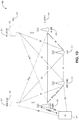
- FIG. 1E illustrates a non-roaming 5G system architecture in accordance with some aspects.
- FIG. 2 illustrates a network-based solution for signal robustness information communicated to eNB for SRVCC handover determination, in accordance with some aspects.
- FIG. 3 illustrates example SDP communications which can be used for dynamic adaptation of maximum PLR for SRVCC handover optimization, in accordance with some aspects.
- FIG. 4 illustrates example PLR splits for downlink and uplink paths between two UEs in an LTE network, in accordance with some aspects.
- FIG. 5 illustrates a block diagram of a communication device such as an evolved Node-B (eNB), a new generation Node-B (gNB), an access point (AP), a wireless station (STA), a mobile station (MS), or a user equipment (UE), in accordance with some aspects.
- eNB evolved Node-B
- gNB new generation Node-B
- AP access point
- STA wireless station
- MS mobile station
- UE user equipment
- FIG. 1A illustrates an architecture of a network in accordance with some aspects.
- the network 140 A is shown to include user equipment (UE) 101 and UE 102 .
- the UEs 101 and 102 are illustrated as smartphones (e.g., handheld touchscreen mobile computing devices connectable to one or more cellular networks) but may also include any mobile or non-mobile computing device, such as Personal Data Assistants (PDAs), pagers, laptop computers, desktop computers, wireless handsets, drones, or any other computing device including a wired and/or wireless communications interface.
- PDAs Personal Data Assistants
- the UEs 101 and 102 can be collectively referred to herein as UE 101 , and UE 101 can be used to perform one or more of the techniques disclosed herein.
- radio links described herein may operate according to any exemplary radio communication technology and/or standard.
- LTE and LTE-Advanced are standards for wireless communications of high-speed data for UE such as mobile telephones.
- carrier aggregation is a technology according to which multiple carrier signals operating on different frequencies may be used to carry communications for a single UE, thus increasing the bandwidth available to a single device.
- carrier aggregation may be used where one or more component carriers operate on unlicensed frequencies.
- LAA Licensed-Assisted Access
- CA flexible carrier aggregation
- Rel-13 LAA system focuses on the design of downlink operation on unlicensed spectrum via CA
- Rel-14 enhanced LAA (eLAA) system focuses on the design of uplink operation on unlicensed spectrum via CA.
- aspects described herein can be used in the context of any spectrum management scheme including, for example, dedicated licensed spectrum, unlicensed spectrum, (licensed) shared spectrum (such as Licensed Shared Access (LSA) in 2.3-2.4 GHz, 3.4-3.6 GHz, 3.6-3.8 GHz, and further frequencies and Spectrum Access System (SAS) in 3.55-3.7 GHz and further frequencies).
- LSA Licensed Shared Access
- SAS Spectrum Access System
- Applicable exemplary spectrum bands include IMT (International Mobile Telecommunications) spectrum (including 450-470 MHz, 790-960 MHz, 1710-2025 MHz, 2110-2200 MHz, 2300-2400 MHz, 2500-2690 MHz, 698-790 MHz, 610-790 MHz, 3400-3600 MHz, to name a few), IMT-advanced spectrum, IMT-2020 spectrum (expected to include 3600-3800 MHz, 3.5 GHz bands, 700 MHz bands, bands within the 24.25-86 GHz range, for example), spectrum made available under the Federal Communications Commission's “Spectrum Frontier” 5G initiative (including 27.5-28.35 GHz, 29.1-29.25 GHz, 31-31.3 GHz, 37-38.6 GHz, 38.6-40 GHz, 42-42.5 GHz, 57-64 GHz, 71-76 GHz, 81-86 GHz and 92-94 GHz, etc), the ITS (Intelligent Transport Systems) band of 5.9 GHz (
- the scheme can be used on a secondary basis on bands such as the TV White Space bands (typically below 790 MHz) wherein particular the 400 MHz and 700 MHz bands can be employed.
- TV White Space bands typically below 790 MHz
- 400 MHz and 700 MHz bands can be employed.
- PMSE Program Making and Special Events
- medical, health, surgery, automotive, low-latency, drones, and the like are examples of vertical markets.
- any of the UEs 101 and 102 can comprise an Internet-of-Things (IoT) UE or a Cellular IoT (CIoT) UE, which can comprise a network access layer designed for low-power IoT applications utilizing short-lived UE connections.
- IoT Internet-of-Things
- CIoT Cellular IoT
- any of the UEs 101 and 102 can include a narrowband (NB) IoT UE (e.g., such as an enhanced NB-IoT (eNB-IoT) UE and Further Enhanced (FeNB-IoT) UE).
- NB narrowband
- eNB-IoT enhanced NB-IoT
- FeNB-IoT Further Enhanced
- An IoT UE can utilize technologies such as machine-to-machine (M2M) or machine-type communications (MTC) for exchanging data with an MTC server or device via a public land mobile network (PLMN), Proximity-Based Service (ProSe) or device-to-device (D2D) communication, sensor networks, or IoT networks.
- M2M or MTC exchange of data may be a machine-initiated exchange of data.
- An IoT network includes interconnecting IoT UEs, which may include uniquely identifiable embedded computing devices (within the Internet infrastructure), with short-lived connections.
- the IoT UEs may execute background applications (e.g., keep-alive messages, status updates, etc.) to facilitate the connections of the IoT network.
- NB-IoT devices can be configured to operate in a single physical resource block (PRB) and may be instructed to retune two different PRBs within the system bandwidth.
- an eNB-IoT UE can be configured to acquire system information in one PRB, and then it can retune to a different PRB to receive or transmit data.
- any of the UEs 101 and 102 can include enhanced MTC (eMTC) UEs or further enhanced MTC (FeMTC) UEs.
- eMTC enhanced MTC
- FeMTC enhanced MTC
- the UEs 101 and 102 may be configured to connect, e.g., communicatively couple, with a radio access network (RAN) 110 .
- the RAN 110 may be, for example, an Evolved Universal Mobile Telecommunications System (UMTS) Terrestrial Radio Access Network (E-UTRAN), a NextGen RAN (NG RAN), or some other type of RAN.
- UMTS Evolved Universal Mobile Telecommunications System
- E-UTRAN Evolved Universal Mobile Telecommunications System
- NG RAN NextGen RAN
- the UEs 101 and 102 utilize connections 103 and 104 , respectively, each of which comprises a physical communications interface or layer (discussed in further detail below); in this example, the connections 103 and 104 are illustrated as an air interface to enable communicative coupling, and can be consistent with cellular communications protocols, such as a Global System for Mobile Communications (GSM) protocol, a code-division multiple access (CDMA) network protocol, a Push-to-Talk (PTT) protocol, a PTT over Cellular (POC) protocol, a Universal Mobile Telecommunications System (UMTS) protocol, a 3GPP Long Term Evolution (LTE) protocol, a fifth generation (5G) protocol, a New Radio (NR) protocol, and the like.
- GSM Global System for Mobile Communications
- CDMA code-division multiple access
- PTT Push-to-Talk
- POC PTT over Cellular
- UMTS Universal Mobile Telecommunications System
- LTE Long Term Evolution
- 5G fifth generation
- NR New Radio
- the network 140 A can include a core network (CN) 120 .
- CN core network
- NG RAN and NG Core are discussed herein in reference to, e.g., FIG. 1B , FIG. 1C , FIG. 1D , and FIG. 1E .
- the UEs 101 and 102 may further directly exchange communication data via a ProSe interface 105 .
- the ProSe interface 105 may alternatively be referred to as a sidelink interface comprising one or more logical channels, including but not limited to a Physical Sidelink Control Channel (PSCCH), a Physical Sidelink Shared Channel (PSSCH), a Physical Sidelink Discovery Channel (PSDCH), and a Physical Sidelink Broadcast Channel (PSBCH).
- PSCCH Physical Sidelink Control Channel
- PSSCH Physical Sidelink Shared Channel
- PSDCH Physical Sidelink Discovery Channel
- PSBCH Physical Sidelink Broadcast Channel
- the UE 102 is shown to be configured to access an access point (AP) 106 via connection 107 .
- the connection 107 can comprise a local wireless connection, such as, for example, a connection consistent with any IEEE 802.11 protocol, according to which the AP 106 can comprise a wireless fidelity (WiFi®) router.
- WiFi® wireless fidelity
- the AP 106 is shown to be connected to the Internet without connecting to the core network of the wireless system (described in further detail below).
- the RAN 110 can include one or more access nodes that enable the connections 103 and 104 .
- These access nodes can be referred to as base stations (BSs), NodeBs, evolved NodeBs (eNBs), Next Generation NodeBs (gNBs), RAN nodes, and the like, and can comprise ground stations (e.g., terrestrial access points) or satellite stations providing coverage within a geographic area (e.g., a cell).
- the communication nodes 111 and 112 can be transmission/reception points (TRPs). In instances when the communication nodes 111 and 112 are NodeBs (e.g., eNBs or gNBs), one or more TRPs can function within the communication cell of the NodeBs.
- TRPs transmission/reception points
- the RAN 110 may include one or more RAN nodes for providing macrocells, e.g., macro RAN node 111 , and one or more RAN nodes for providing femtocells or picocells (e.g., cells having smaller coverage areas, smaller user capacity, or higher bandwidth compared to macrocells), e.g., low power (LP) RAN node 112 .
- macro RAN node 111 e.g., macro RAN node 111
- femtocells or picocells e.g., cells having smaller coverage areas, smaller user capacity, or higher bandwidth compared to macrocells
- LP low power
- any of the RAN nodes 111 and 112 can terminate the air interface protocol and can be the first point of contact for the UEs 101 and 102 .
- any of the RAN nodes 111 and 112 can fulfill various logical functions for the RAN 110 including, but not limited to, radio network controller (RNC) functions such as radio bearer management, uplink and downlink dynamic radio resource management and data packet scheduling, and mobility management.
- RNC radio network controller
- any of the nodes 111 and/or 112 can be a new generation node-B (gNB), an evolved node-B (eNB), or another type of RAN node.
- gNB new generation node-B
- eNB evolved node-B
- the UEs 101 and 102 can be configured to communicate using Orthogonal Frequency-Division Multiplexing (OFDM) communication signals with each other or with any of the RAN nodes 111 and 112 over a multicarrier communication channel in accordance various communication techniques, such as, but not limited to, an Orthogonal Frequency-Division Multiple Access (OFDMA) communication technique (e.g., for downlink communications) or a Single Carrier Frequency Division Multiple Access (SC-FDMA) communication technique (e.g., for uplink and ProSe for sidelink communications), although such aspects are not required.
- OFDM signals can comprise a plurality of orthogonal subcarriers.
- a downlink resource grid can be used for downlink transmissions from any of the RAN nodes 111 and 112 to the UEs 101 and 102 , while uplink transmissions can utilize similar techniques.
- the grid can be a time-frequency grid, called a resource grid or time-frequency resource grid, which is the physical resource in the downlink in each slot.
- a time-frequency plane representation may be used for OFDM systems, which makes it applicable for radio resource allocation.
- Each column and each row of the resource grid may correspond to one OFDM symbol and one OFDM subcarrier, respectively.
- the duration of the resource grid in the time domain may correspond to one slot in a radio frame.
- the smallest time-frequency unit in a resource grid may be denoted as a resource element.
- Each resource grid may comprise a number of resource blocks, which describe the mapping of certain physical channels to resource elements.
- Each resource block may comprise a collection of resource elements; in the frequency domain, this may, in some aspects, represent the smallest quantity of resources that currently can be allocated. There may be several different physical downlink channels that are conveyed using such resource blocks.
- the physical downlink shared channel may carry user data and higher-layer signaling to the UEs 101 and 102 .
- the physical downlink control channel (PDCCH) may carry information about the transport format and resource allocations related to the PDSCH channel, among other things. It may also inform the UEs 101 and 102 about the transport format, resource allocation, and H-ARQ (Hybrid Automatic Repeat Request) information related to the uplink shared channel.
- downlink scheduling (assigning control and shared channel resource blocks to the UE 102 within a cell) may be performed at any of the RAN nodes 111 and 112 based on channel quality information fed back from any of the UEs 101 and 102 .
- the downlink resource assignment information may be sent on the PDCCH used for (e.g., assigned to) each of the UEs 101 and 102 .
- the PDCCH may use control channel elements (CCEs) to convey the control information.
- CCEs control channel elements
- the PDCCH complex-valued symbols may first be organized into quadruplets, which may then be permuted using a sub-block interleaver for rate matching.
- Each PDCCH may be transmitted using one or more of these CCEs, where each CCE may correspond to nine sets of four physical resource elements known as resource element groups (REGs).
- RAGs resource element groups
- QPSK Quadrature Phase Shift Keying
- the PDCCH can be transmitted using one or more CCEs, depending on the size of the downlink control information (DCI) and the channel condition.
- DCI downlink control information
- There can be four or more different PDCCH formats defined in LTE with different numbers of CCEs (e.g., aggregation level, L 1, 2, 4, or 8).
- Some aspects may use concepts for resource allocation for control channel information that are an extension of the above-described concepts.
- some aspects may utilize an enhanced physical downlink control channel (EPDCCH) that uses PDSCH resources for control information transmission.
- the EPDCCH may be transmitted using one or more enhanced control channel elements (ECCEs). Similar to above, each ECCE may correspond to nine sets of four physical resource elements known as an enhanced resource element groups (EREGs). An ECCE may have other numbers of EREGs according to some arrangements.
- EPCCH enhanced physical downlink control channel
- ECCEs enhanced control channel elements
- each ECCE may correspond to nine sets of four physical resource elements known as an enhanced resource element groups (EREGs).
- EREGs enhanced resource element groups
- An ECCE may have other numbers of EREGs according to some arrangements.
- the RAN 110 is shown to be communicatively coupled to a core network (CN) 120 via an S1 interface 113 .
- the CN 120 may be an evolved packet core (EPC) network, a NextGen Packet Core (NPC) network, or some other type of CN (e.g., as illustrated in reference to FIGS. 1B-1I ).
- EPC evolved packet core
- NPC NextGen Packet Core
- the S1 interface 113 is split into two parts: the S1-U interface 114 , which carries traffic data between the RAN nodes 111 and 112 and the serving gateway (S-GW) 122 , and the S1-mobility management entity (MME) interface 115 , which is a signaling interface between the RAN nodes 111 and 112 and MMEs 121 .
- MME S1-mobility management entity
- the CN 120 comprises the MMEs 121 , the S-GW 122 , the Packet Data Network (PDN) Gateway (P-GW) 123 , and a home subscriber server (HSS) 124 .
- the MMEs 121 may be similar in function to the control plane of legacy Serving General Packet Radio Service (GPRS) Support Nodes (SGSN).
- the MMEs 121 may manage mobility aspects in access such as gateway selection and tracking area list management.
- the HSS 124 may comprise a database for network users, including subscription-related information to support the network entities' handling of communication sessions.
- the CN 120 may comprise one or several HSSs 124 , depending on the number of mobile subscribers, on the capacity of the equipment, on the organization of the network, etc.
- the HSS 124 can provide support for routing/roaming, authentication, authorization, naming/addressing resolution, location dependencies, etc.
- the S-GW 122 may terminate the S1 interface 113 towards the RAN 110 , and routes data packets between the RAN 110 and the CN 120 .
- the S-GW 122 may be a local mobility anchor point for inter-RAN node handovers and also may provide an anchor for inter-3GPP mobility.
- Other responsibilities of the S-GW 122 may include a lawful intercept, charging, and some policy enforcement.
- the P-GW 123 may terminate an SGi interface toward a PDN.
- the P-GW 123 may route data packets between the EPC network 120 and external networks such as a network including the application server 184 (alternatively referred to as application function (AF)) via an Internet Protocol (IP) interface 125 .
- the P-GW 123 can also communicate data to other external networks 131 A, which can include the Internet, IP multimedia subsystem (IPS) network, and other networks.
- the application server 184 may be an element offering applications that use IP bearer resources with the core network (e.g., UMTS Packet Services (PS) domain, LTE PS data services, etc.).
- PS UMTS Packet Services
- the P-GW 123 is shown to be communicatively coupled to an application server 184 via an IP interface 125 .
- the application server 184 can also be configured to support one or more communication services (e.g., Voice-over-Internet Protocol (VoIP) sessions, PTT sessions, group communication sessions, social networking services, etc.) for the UEs 101 and 102 via the CN 120 .
- VoIP Voice-over-Internet Protocol
- the P-GW 123 may further be a node for policy enforcement and charging data collection.
- Policy and Charging Rules Function (PCRF) 126 is the policy and charging control element of the CN 120 .
- PCRF Policy and Charging Rules Function
- HPLMN Home Public Land Mobile Network
- IP-CAN Internet Protocol Connectivity Access Network
- H-PCRF Home PCRF
- V-PCRF Visited PCRF
- the PCRF 126 may be communicatively coupled to the application server 184 via the P-GW 123 .
- the application server 184 may signal the PCRF 126 to indicate a new service flow and select the appropriate Quality of Service (QoS) and charging parameters.
- the PCRF 126 may provision this rule into a Policy and Charging Enforcement Function (PCEF) (not shown) with the appropriate traffic flow template (TFT) and QoS class of identifier (QCI), which commences the QoS and charging as specified by the application server 184 .
- PCEF Policy and Charging Enforcement Function
- TFT traffic flow template
- QCI QoS class of identifier
- any of the nodes 111 or 112 can be configured to communicate to the UEs 101 , 102 (e.g., dynamically) an antenna panel selection and a receive (Rx) beam selection that can be used by the UE for data reception on a physical downlink shared channel (PDSCH) as well as for channel state information reference signal (CSI-RS) measurements and channel state information (CSI) calculation.
- PDSCH physical downlink shared channel
- CSI-RS channel state information reference signal
- CSI channel state information
- any of the nodes 111 or 112 can be configured to communicate to the UEs 101 , 102 (e.g., dynamically) an antenna panel selection and a transmit (Tx) beam selection that can be used by the UE for data transmission on a physical uplink shared channel (PUSCH) as well as for sounding reference signal (SRS) transmission.
- Tx transmit
- PUSCH physical uplink shared channel
- SRS sounding reference signal
- the communication network 140 A can be an IoT network.
- One of the current enablers of IoT is the narrowband-IoT (NB-IoT).
- NB-IoT has objectives such as coverage extension, UE complexity reduction, long battery lifetime, and backward compatibility with the LTE network.
- NB-IoT aims to offer deployment flexibility allowing an operator to introduce NB-IoT using a small portion of its existing available spectrum, and operate in one of the following three modalities: (a) standalone deployment (the network operates in re-farmed GSM spectrum); (b) in-band deployment (the network operates within the LTE channel); and (c) guard-band deployment (the network operates in the guard band of legacy LTE channels).
- NB-IoT further enhanced NB-IoT
- support for NB-IoT in small cells can be provided (e.g., in microcell, picocell or femtocell deployments).
- NB-IoT systems face for small cell support is the UL/DL link imbalance, where for small cells the base stations have lower power available compared to macro-cells, and, consequently, the DL coverage can be affected and/or reduced.
- some NB-IoT UEs can be configured to transmit at maximum power if repetitions are used for UL transmission. This may result in large inter-cell interference in dense small cell deployments.
- the UE 101 can support connectivity to a 5G core network (5GCN) and can be configured to operate with Early Data Transmission (EDT) in a communication architecture that supports one or more of Machine Type Communications (MTC), enhanced MTC (eMTC), further enhanced MTC (feMTC), even further enhanced MTC (efeMTC), and narrowband Internet-of-Things (NB-IoT) communications.
- EDT Early Data Transmission
- MTC Machine Type Communications
- eMTC enhanced MTC
- feMTC further enhanced MTC
- efeMTC even further enhanced MTC
- NB-IoT narrowband Internet-of-Things
- a UE When a UE wants to make a new RRC connection, it first transmits one or more preambles, which can be referred to as PRACH procedure message 1 (MSG1).
- MSG4 can also indicate UE to immediately go to IDLE mode.
- TBS transport block size
- the transport block size (TBS) scheduled by the UL grant received for the MSG3 to transmit UL data for EDT needs to be larger than the TBS scheduled by the legacy grant.
- the UE can indicate its intention of using the early data transmission via MSG1 using a separate PRACH resource partition.
- eNB From MSG1, eNB knows that it has to provide a grant scheduling TBS values that may differ from legacy TBS for MSG3 in the random-access response (RAR or MSG2) so that the UE can transmit UL data in MSG3 for EDT.
- RAR random-access response
- the eNB may not exactly know what would be the size of UL data the UE wants to transmit for EDT and how large a UL grant for MSG3 would be needed, though a minimum and a maximum TBS for the UL grant could be defined.
- the following two scenarios may occur: (a) The UL grant provided in RAR is larger than the UL data plus header. In this case, layer 1 needs to add one or more padding bits in the remaining grant.
- PRACH procedure can be used interchangeably with the term “Random Access procedure” or “RA procedure”.
- UE 101 can be configured for dynamic adaptation of maximum packet loss rate (PLR) for SRVCC handover using session description protocol (SDP). More specifically, UE 101 can include PLR preferences 190 A and one or more SDP messages exchanged with another UE during an SDP negotiation.
- the PLR preferences 190 A can be detected by a core network function such as PCRF 126 , and PCRF can provide one or more PLR thresholds to the corresponding eNB (e.g., 111 ) for use in determining whether to send an SRVCC handover command 192 A two UE 101 . Further description of techniques for dynamic adaptation of maximum PLR for SRVCC handover optimization using SDP is disclosed hereinbelow.
- FIG. 1B is a simplified diagram of a next generation (NG) system architecture 140 B in accordance with some aspects.
- the NG system architecture 140 B includes RAN 110 and a 5G network core (5GC) 120 .
- the NG-RAN 110 can include a plurality of nodes, such as gNBs 128 and NG-eNBs 130 .
- the core network 120 can include an access and mobility function (AMF) 132 and/or a user plane function (UPF) 134 .
- the AMF 132 and the UPF 134 can be communicatively coupled to the gNBs 128 and the NG-eNBs 130 via NG interfaces. More specifically, in some aspects, the gNBs 128 and the NG-eNBs 130 can be connected to the AMF 132 by NG-C interfaces, and to the UPF 134 by NG-U interfaces.
- the gNBs 128 and the NG-eNBs 130 can be coupled to each other via Xn interfaces.
- a gNB 128 can include a node providing new radio (NR) user plane and control plane protocol termination towards the UE and is connected via the NG interface to the 5GC 120 .
- an NG-eNB 130 can include a node providing evolved universal terrestrial radio access (E-UTRA) user plane and control plane protocol terminations towards the UE and is connected via the NG interface to the 5GC 120 .
- E-UTRA evolved universal terrestrial radio access
- the NG system architecture 140 B can use reference points between various nodes as provided by 3GPP Technical Specification (TS) 23.501 (e.g., V15.4.0, 2018-12).
- TS 3GPP Technical Specification
- each of the gNBs 128 and the NG-eNBs 130 can be implemented as a base station, a mobile edge server, a small cell, a home eNB, and so forth.
- node 128 can be a master node (MN) and node 130 can be a secondary node (SN) in a 5G architecture.
- the MN 128 can be connected to the AMF 132 via an NG-C interface and to the SN 128 via an XN-C interface.
- the MN 128 can be connected to the UPF 134 via an NG-U interface and to the SN 128 via an XN-U interface.
- FIG. 1C illustrates a functional split between NG-RAN and the 5G Core (5GC) in accordance with some aspects.
- 5GC 5G Core
- FIG. 1C there is illustrated a more detailed diagram of the functionalities that can be performed by the gNBs 128 and the NG-eNBs 130 within the NG-RAN 110 , as well as the AMF 132 , the UPF 134 , and the SMF 136 within the 5GC 120 .
- the 5GC 120 can provide access to the Internet 138 to one or more devices via the NG-RAN 110 .
- the gNBs 128 and the NG-eNBs 130 can be configured to host the following functions: functions for Radio Resource Management (e.g., inter-cell radio resource management 129 A, radio bearer control 129 B, connection mobility control 129 C, radio admission control 129 D, dynamic allocation of resources to UEs in both uplink and downlink (scheduling) 129 F); IP header compression, encryption and integrity protection of data; selection of an AMF at UE attachment when no routing to an AMF can be determined from the information provided by the UE; routing of User Plane data towards UPF(s); routing of Control Plane information towards AMF; connection setup and release; scheduling and transmission of paging messages (originated from the AMF); scheduling and transmission of system broadcast information (originated from the AMF or Operation and Maintenance); measurement and measurement reporting configuration for mobility and scheduling 129 E; transport level packet marking in the uplink; session management; support of network slicing; QoS flow management and mapping to data radio bearers; support of UEs in RRC
- the AMF 132 can be configured to host the following functions, for example: NAS signaling termination; NAS signaling security 133 A; access stratum (AS) security control; inter-core network (CN) node signaling for mobility between 3GPP access networks; idle state/mode mobility handling 133 B, including mobile device, such as a UE reachability (e.g., control and execution of paging retransmission); registration area management; support of intra-system and inter-system mobility; access authentication; access authorization including check of roaming rights; mobility management control (subscription and policies); support of network slicing; and/or SMF selection, among other functions.
- NAS signaling termination NAS signaling security 133 A
- AS access stratum
- CN inter-core network
- the UPF 134 can be configured to host the following functions, for example: mobility anchoring 135 A (e.g., anchor point for Intra-/Inter-RAT mobility); packet data unit (PDU) handling 135 B (e.g., external PDU session point of interconnect to data network); packet routing and forwarding; packet inspection and user plane part of policy rule enforcement; traffic usage reporting; uplink classifier to support routing traffic flows to a data network; branching point to support multi-homed PDU session; QoS handling for user plane, e.g., packet filtering, gating, UL/DL rate enforcement; uplink traffic verification (SDF to QoS flow mapping); and/or downlink packet buffering and downlink data notification triggering, among other functions.
- mobility anchoring 135 A e.g., anchor point for Intra-/Inter-RAT mobility
- PDU packet data unit
- PDU packet data unit
- packet routing and forwarding packet inspection and user plane part of policy rule enforcement
- traffic usage reporting uplink classifier to support routing traffic flows to
- the Session Management function (SMF) 136 can be configured to host the following functions, for example: session management; UE IP address allocation and management 137 A; selection and control of user plane function (UPF); PDU session control 137 B, including configuring traffic steering at UPF 134 to route traffic to proper destination; control part of policy enforcement and QoS; and/or downlink data notification, among other functions.
- SMF Session Management function
- UPF user plane function
- PDU session control 137 B including configuring traffic steering at UPF 134 to route traffic to proper destination; control part of policy enforcement and QoS; and/or downlink data notification, among other functions.
- FIG. 1D illustrates an example Evolved Universal Terrestrial Radio Access (E-UTRA) New Radio Dual Connectivity (EN-DC) architecture, in accordance with some aspects.
- the EN-DC architecture 140 D includes radio access network (or E-TRA network, or E-TRAN) 110 and EPC 120 .
- the EPC 120 can include MMEs 121 and S-GWs 122 .
- the E-UTRAN 110 can include nodes 111 (e.g., eNBs) as well as Evolved Universal Terrestrial Radio Access New Radio (EN) next generation evolved Node-Bs (en-gNBs) 128 .
- nodes 111 e.g., eNBs
- EN Evolved Universal Terrestrial Radio Access New Radio
- en-gNBs next generation evolved Node-Bs
- en-gNBs 128 can be configured to provide NR user plane and control plane protocol terminations towards the UE 102 and acting as Secondary Nodes (or SgNBs) in the EN-DC communication architecture 140 D.
- the eNBs 111 can be configured as master nodes (or MeNBs) and the eNBs 128 can be configured as secondary nodes (or SgNBs) in the EN-DC communication architecture 140 D. As illustrated in FIG. 1D , the eNBs 111 are connected to the EPC 120 via the S1 interface and to the EN-gNBs 128 via the X2 interface.
- the EN-gNBs (or SgNBs) 128 may be connected to the EPC 120 via the S1-U interface, and to other EN-gNBs via the X2-U interface.
- the SgNB 128 can communicate with the UE 102 via a UU interface (e.g., using signaling radio bearer type 3, or SRB3 communications as illustrated in FIG. 1D ), and with the MeNB 111 via an X2 interface (e.g., X2-C interface).
- the MeNB 111 can communicate with the UE 102 via a UU interface.
- FIG. 1D is described in connection with EN-DC communication environment, other types of dual connectivity communication architectures (e.g., when the UE 102 is connected to a master node and a secondary node) can also use the techniques disclosed herein.
- the MeNB 111 can be connected to the MME 121 via S1-MME interface and to the SgNB 128 via an X2-C interface. In some aspects, the MeNB 111 can be connected to the SGW 122 via S1-U interface and to the SgNB 128 via an X2-U interface. In some aspects associated with dual connectivity (DC) and/or MultiRate-DC (MR-DC), the Master eNB (MeNB) can offload user plane traffic to the Secondary gNB (SgNB) via split bearer or SCG (Secondary Cell Group) split bearer.
- DC dual connectivity
- MR-DC MultiRate-DC
- the Master eNB can offload user plane traffic to the Secondary gNB (SgNB) via split bearer or SCG (Secondary Cell Group) split bearer.
- FIG. 1E illustrates a non-roaming 5G system architecture in accordance with some aspects.
- a 5G system architecture 140 E in a reference point representation. More specifically, UE 102 can be in communication with RAN 110 as well as one or more other 5G core (5GC) network entities.
- 5GC 5G core
- the 5G system architecture 140 E includes a plurality of network functions (NFs), such as access and mobility management function (AMF) 132 , session management function (SMF) 136 , policy control function (PCF) 148 , application function (AF) 150 , user plane function (UPF) 134 , network slice selection function (NSSF) 142 , authentication server function (AUSF) 144 , and unified data management (UDM)/home subscriber server (HSS) 146 .
- the UPF 134 can provide a connection to a data network (DN) 152 , which can include, for example, operator services, Internet access, or third-party services.
- DN data network
- the AMF 132 can be used to manage access control and mobility and can also include network slice selection functionality.
- the SMF 136 can be configured to set up and manage various sessions according to a network policy.
- the UPF 134 can be deployed in one or more configurations according to a desired service type.
- the PCF 148 can be configured to provide a policy framework using network slicing, mobility management, and roaming (similar to PCRF in a 4G communication system).
- the UDM can be configured to store subscriber profiles and data (similar to an HSS in a 4G communication system).
- the 5G system architecture 140 E includes an IP multimedia subsystem (IMS) 168 E as well as a plurality of IP multimedia core network subsystem entities, such as call session control functions (CSCFs). More specifically, the IMS 168 E includes a CSCF, which can act as a proxy CSCF (P-CSCF) 162 E, a serving CSCF (S-CSCF) 164 E, an emergency CSCF (E-CSCF) (not illustrated in FIG. 1E ), or interrogating CSCF (I-CSCF) 166 E.
- P-CSCF 162 E can be configured to be the first contact point for the UE 102 within the IM subsystem (IMS) 168 E.
- the S-CSCF 164 E can be configured to handle the session states in the network, and the E-CSCF can be configured to handle certain aspects of emergency sessions such as routing an emergency request to the correct emergency center or PSAP.
- the I-CSCF 166 E can be configured to function as the contact point within an operator's network for all IMS connections destined to a subscriber of that network operator, or a roaming subscriber currently located within that network operator's service area.
- the I-CSCF 166 E can be connected to another IP multimedia network 170 E, e.g. an IMS operated by a different network operator.
- the UDM/HSS 146 can be coupled to an application server 160 E, which can include a telephony application server (TAS) or another application server (AS).
- the AS 160 E can be coupled to the IMS 168 E via the S-CSCF 164 E or the I-CSCF 166 E.
- the 5G system architecture 140 E can use unified access barring mechanism using one or more of the techniques described herein, which access barring mechanism can be applied for all RRC states of the UE 102 , such as RRC_IDLE, RRC_CONNECTED, and RRC_INACTIVE states.
- the 5G system architecture 140 E can be configured to use 5G access control mechanism techniques described herein, based on access categories that can be categorized by a minimum default set of access categories, which are common across all networks.
- This functionality can allow the public land mobile network PLMN, such as a visited PLMN (VPLMN) to protect the network against different types of registration attempts, enable acceptable service for the roaming subscriber and enable the VPLMN to control access attempts aiming at receiving certain basic services. It also provides more options and flexibility to individual operators by providing a set of access categories, which can be configured and used in operator-specific ways.
- PLMN public land mobile network
- VPN visited PLMN
- FIG. 1E illustrates the following reference points: N 1 (between the UE 102 and the AMF 132 ), N 2 (between the RAN 110 and the AMF 132 ), N 3 (between the RAN 110 and the UPF 134 ), N 4 (between the SMF 136 and the UPF 134 ), N 5 (between the PCF 148 and the AF 150 , not shown), N 6 (between the UPF 134 and the DN 152 ), N 7 (between the SMF 136 and the PCF 148 , not shown), N 8 (between the UDM 146 and the AMF 132 , not shown), N 9 (between two UPFs 134 , not shown), N 10 (between the UDM 146 and the SMF 136 , not shown), N 11 (between the AMF 132 and the SMF 136 , not shown), N 12 (between the AUSF 144 and the AMF 132 , not shown), N 13 (between the AU
- Techniques disclosed herein can be used to enable dynamically adapting the PLR thresholds at the eNB toward enabling SRVCC handover optimization for VoLTE calls. More specifically, techniques disclosed herein take into account the dynamically varying coverage conditions on both ends of the communication link to be able to optimize the SRVCC handover thresholds. In addition to the negotiated codecs and codec modes, the end-to-end quality and robustness of the VoLTE connection also depend on the dynamic radio conditions on both ends of the communication link.
- the PLR parameter e.g., PLR threshold
- PCRF e.g., maxPLR, as illustrated in FIG. 2
- techniques disclosed herein can be used for further refinement on PLR thresholds determination and can be considered on a per session basis depending on the dynamic radio conditions.
- techniques disclosed herein can be used to improve enhanced voice over LTE performance (EVOLP). It is important to maintain voice quality on LTE as high as possible and, therefore, avoiding or delaying SRVCC in order to minimize the negative impact on user experience for VoLTE subscribers in areas with weak LTE coverage.
- VoLTE calls could be handed over to 2/3G circuit switched (CS) network (e.g., a legacy network such as WCDMA network) unnecessarily via SRVCC handover (HO) even though the VoLTE call can survive weak coverage in the LTE (packet switched or PS) network.
- CS circuit switched
- HO SRVCC handover
- increased robustness of speech calls can be enabled by the selection of codecs and their configuration, in-call dynamic rate, mode adaptation, and application layer full redundancy.
- the EVS codec can be used for higher robustness against transmission errors in comparison to the AMR and AMR-WB codecs by application-layer partial redundancy.
- a PLR threshold parameter e.g., maxPLR
- maxPLR can be used (e.g., as a maximum tolerable PLR threshold) to inform the eNB about the robustness of the selected codec.
- the robustness (i.e., maxPLR) information can be conveyed to the eNB using either the signaling from the network (e.g., signaling from the PCRF) or signaling from the UE.
- the eNB can derive the related SRVCC thresholds (which can be implementation dependent) from the maxPLR parameter.
- different codec modes can be associated with different maxPLR values, i.e., different robustness can be associated with different codecs or codec modes used by a UE for voice communication via VoLTE.
- FIG. 2 illustrates a network-based solution for signal robustness information communicated to eNB for SRVCC handover determination, in accordance with some aspects.
- diagram 200 illustrates various communications between network entities in connection with dynamic adaptation of PLR for SRVCC handover optimization.
- the network entities illustrated in FIG. 2 can include an IP multimedia subsystem (IMS) 208 , a first UE 101 associated with a first eNB 111 and a first PCRF 126 , as well as a second UE 202 associated with a second eNB 204 and a second PCRF 206 .
- IMS IP multimedia subsystem
- the network-based solution illustrated in FIG. 2 relies on the fact that the information on the negotiated codecs and configurations (or codec modes) for the session is available in the PCRFs (e.g., 126 and 206 ) through its knowledge of the SDP that contains the negotiated session parameters. More specifically, during an SDP negotiation procedure 218 , SDP messages such as an SDP offer 212 and an SDP answer 216 are exchanged between UE 101 and UE 202 . Such SDP communication exchanges can be accessed by the PCRF entities 126 and 206 , and the PCRF entities would have knowledge of the information contained in the SDP messages.
- the PCRF entities 126 and 206 can derive the relevant robustness parameter information (e.g., Maximum Packet Loss Rate or maxPLR) and signal this information to the corresponding eNBs 111 and 204 during operations 215 and 217 .
- the derivation of the robustness parameter information (maxPLR) can be based on the negotiated codec modes (which can be obtained from the SDP messages) or can be performed subject to a standardized mapping rule, e.g., with an indication of packet loss rate for each codec mode and calculation of the maxPLR based on the negotiated codec modes.
- the PCRF entities 126 and 206 by default do not know the multimedia telephony service for IMS (MTSI) client (e.g., UEs 101 and 202 ) adaptation behavior, and would, therefore, set the robustness parameter maxPLR based on the least robust codec mode among the negotiated codec configurations.
- MMSI multimedia telephony service for IMS
- the PCRF entities 126 and 206 could set the robustness parameter based on the most robust codec mode, and thereby enabling a more optimized SRVCC handover performance.
- indication to the PCRF entities can be enabled via an SDP parameter (e.g., SDP parameter “adapt”).
- SRVCC enhancements rely on the fixed allocation of PLR associated with an uplink (UL) communication link (e.g., UL PLR) and PLR associated with a downlink (DL) communication link (e.g., DL PLR) across the eNBs.
- UL PLR uplink
- DL PLR downlink
- Such enhancements may not always provide the most optimal results in adjusting the SRVCC handover thresholds (e.g., when one of the eNBs enjoys very good radio conditions it is unable to dynamically raise the packet loss rates that can be tolerated at the far-end eNB which would allow the far-end eNB to delay the SRVCC handover for the negotiated codec configurations).
- a more dynamic allocation policy on UL PLR and DL PLR that considers the local RAN conditions on both ends of the link may, therefore, allow realizing further optimizations on the SRVCC handover thresholds.
- the end-to-end quality and robustness of the VoLTE connection between UEs 101 and 202 also depend on the radio conditions on both ends of the link.
- the maxPLR parameter derived by the PCRF entities 126 and 206 i.e., in the network-based architecture in FIG. 2
- the corresponding eNBs e.g., at operations 215 and 217
- further refinements related to maxPLR determination can be considered on a per session basis depending on the dynamic radio conditions.
- each of the UEs may consider its de-jitter buffer management (JBM) and/or packet loss concealment (PLC) capabilities to derive a recommended maximum end-to-end packet loss rate (e.g., E2E MAXPLR_A for UE 101 and E2E MAXPLR_B for UE 202 ) that the UE can tolerate for a given codec/mode when using its JBM and PLC implementation, and signal this parameter, or some indication derived from it, to the network.
- JBM de-jitter buffer management
- PLC packet loss concealment
- UE PLR preferences e.g., 240 and 230
- E2E MAXPLR value can be included in the corresponding SDP messages (e.g., 212 and 216 ) which can be intercepted by the PCRF entities 126 and 206 at operations 219 and 221 respectively.
- the robustness parameter values used by the eNBs 111 and 204 may then use, or be refined based on, the E2E MAXPLR recommendations provided by the UEs.
- a UE with advanced JBM and PLC capabilities may determine a recommended E2E MAXPLR value that is higher than the maxPLR determined by the PCRF entities and corresponding to the most robust codec configuration.
- the PLC and JBM capabilities of the UEs 101 and 202 may be delivering further robustness on top of that delivered by the most robust codec configuration.
- the eNBs 111 and 204 may further delay the SRVCC handover decision even when the PCRF-provided maxPLR value (based on the most robust codec configuration) is exceeded, leading to more optimized SRVCC handovers. Furthermore, since there are typically two radio links in the end-to-end path from the sending terminal to the receiving terminal, the information has to ultimately be shared with the two eNBs ( 111 and 204 ) in the transport path to determine how to set their SRVCC handover thresholds and to achieve the appropriate PLR targets.
- the PLR preferences 240 and 230 with the UE recommended E2E MAXPLR values are additional parameters for consideration by the eNBs, on top of the maxPLR value the eNBs would receive from the PCRF entities 126 and 206 at operations 215 and 217 (in case of the network-based architecture) or from the UE (in case of the UE-based architecture). If this information, or any other information derived from it, is to be signaled to the eNB, defining suitable RAN-level signaling from UE to eNB may be used, e.g., RRC level signaling can be used for communicating the PLR preferences 240 and 230 from the UEs to the corresponding eNBs.
- FIG. 3 illustrates example SDP communications which can be used for dynamic adaptation of maximum PLR for SRVCC handover optimization, in accordance with some aspects.
- SDP message 212 can include an indication of a voice codec 302 and a codec mode 308 for use by UE 101 during a VoLTE call with UE 202 .
- SDP message 212 can include an end to end maximum recommended PLR value (e.g., E2E MAXPLR_A 306 ) that can be tolerated by the UE 101 when receiving voice communication traffic from UE 202 .
- E2E MAXPLR_A 306 an end to end maximum recommended PLR value
- the SDP message 212 can further include a PLR split of the E2E MAXPLR_A 306 indicating PLR values that can be tolerated by UE 101 for the uplink communication traffic from UE 202 to eNB 204 (e.g., ENB_B_UL_PLR 310 ) and the downlink communication traffic from eNB 111 to UE 101 (e.g., ENB_A_DL_PLR 308 ).
- the SDP message 212 can further include a PLR ratio 312 which can be a ratio of the PLR values 308 and 310 .
- the uplink and downlink split of the communication traffic is illustrated in greater detail in FIG. 4 .
- SDP message 216 can include an indication of a voice codec 314 and a codec mode 316 for use by UE 202 during a VoLTE call with UE 101 . Additionally, SDP message 216 can include an end to end maximum recommended PLR value (e.g., E2E MAXPLR_B 318 ) that can be tolerated by the UE 202 when receiving voice communication traffic from UE 101 .
- E2E MAXPLR_B 318 an end to end maximum recommended PLR value
- the SDP message 216 can further include a PLR split of the E2E MAXPLR_B 318 indicating PLR values that can be tolerated by UE 202 for the uplink communication traffic from UE 101 to eNB 111 (e.g., ENB_A_UL_PLR 324 ) and the downlink communication traffic from eNB 204 to UE 202 (e.g., ENB_B_DL_PLR 320 ).
- the SDP message 216 can further include a PLR ratio 324 which can be a ratio of the PLR values 320 and 322 .
- FIG. 4 illustrates example PLR splits for downlink and uplink paths between two UEs in an LTE network, in accordance with some aspects.
- diagram 400 illustrates example voice communication traffic paths 402 and 4044 voice data that is received by the UE 101 and the UE 202 respectively.
- the PCRF entities 126 and 206 can use the PLR preferences 240 and 230 included by the UEs within corresponding SDP messages such as 212 and 216 to generate PLR threshold values 242 / 244 for communication to eNB 111 (e.g., at operation 223 ) and PLR threshold values 232 / 234 for communication to eNB 204 (e.g., at operation 225 ).
- the PLR threshold values associated with communication traffic path 402 includes a PLR threshold value for uplink traffic between the UE 202 and eNB 204 (e.g., PLR_UL_B 242 ) and a PLR threshold value for downlink traffic between eNB 111 and the UE 101 (e.g., PLR_DL_A 244 ).
- the PLR threshold values associated with communication traffic path 404 includes a PLR threshold value for uplink traffic between the UE 101 and eNB 111 (e.g., PLR_UL_A 234 ) and a PLR threshold value for downlink traffic between eNB 204 and the UE 202 (e.g., PLR_DL_B 232 ).
- the determination of the PLR threshold values 232 , 234 , 242 , and 244 by the PCRF entities can be based on the UE preferences 240 and 230 as included within the SDP messages 212 and 216 .
- One of the challenges in setting the handover thresholds is to ensure that the end-to-end error rate across the transport path from the media sender to receiver does not exceed the maximum packet loss rate (maxPLR) that the codec, the PLC implementation, and/or the JBM implementation in the receiving UE can handle.
- maxPLR maximum packet loss rate
- ENB_A_DL_PLR e.g., 308
- ENB_B_UL_PLR e.g., 310
- E2E MAXPLR_A e.g., 306
- ENB_A_DL_PLR 308 is the maximum PLR value to be set as the threshold to trigger SRVCC for the DL connection between eNB 111 and UE 101
- ENB_B_UL_PLR 310 is the maximum PLR value to be set as the threshold to trigger SRVCC for the UL connection between eNB 204 and UE 202 .
- UE 101 can determine the maximum PLR it can tolerate (e.g., E2E MAXPLR_A 306 ) based on its PLC and JBM implementation and then decide how this PLR can be distributed between ENB_A_DL_PLR 308 (PLR for downlink from eNB 111 to UE 101 ) and ENB_B_UL_PLR 310 (PLR for the uplink from UE 202 to eNB 204 .
- E2E MAXPLR_A 306 e.g., E2E MAXPLR_A 306
- ENB_B_UL_PLR 310 PLR for the uplink from UE 202 to eNB 204 .
- UE 101 can decide on the value of eNB_A_DL_PLR 308 based on the evaluation of the local downlink radio conditions between UE 101 and eNB 111 and then determine ENB_B_UL_PLR 310 by subtracting ENB_A_DL_PLR from the maximum end-to-end PLR (E2E MAXPLR_A 306 ).
- the UE 101 can offer its recommended values for maximum end-to-end PLR (E2E MAXPLR_A 306 ), ENB_A_DL_PLR 308 , and ENB_B_UL_PLR 310 in the SDP message (e.g., 212 ).
- both the media receiver and the media sender have means to exchange UL PLR information, in order to dynamically optimize the allocation of DL PLR and UL PLR, and lead to the most optimal selection of the SRVCC handover thresholds on both ends of the link.
- ENB_A_UL_PLR e.g., 322
- ENB_B_DL_PLR e.g., 320
- E2E MAXPLR_B e.g., 318
- ENB_A_UL_PLR 322 is the maximum PLR value to be set as the threshold to trigger SRVCC for the UL connection between eNB 111 and UE 101
- ENB_B_DL_PLR 320 is the maximum PLR value to be set as the threshold to trigger SRVCC for the DL connection between eNB 204 and UE 202 .
- UE 202 can determine the maximum PLR it can tolerate (e.g., E2E MAXPLR_B 318 ) based on its PLC and JBM implementation, and then decide how this PLR can be distributed between ENB_A_UL_PLR 322 and ENB_B_DL_PLR 320 .
- UE 202 can decide on the value of ENB_B_DL_PLR 320 based on the evaluation of the local downlink radio conditions between UE 202 and eNB 204 and then determine ENB_A_UL_PLR 322 by subtracting ENB_B_B_DL_PLR 320 from the maximum end-to-end PLR (E2E MAXPLR_B 318 ).
- UE 202 may then signal its recommended values on maximum end-to-end PLR (E2E MAXPLR_B 318 at UE 202 ), ENB_A_UL_PLR 322 , and ENB_B_DL_PLR 320 in the SDP message (e.g., 216 ).
- E2E MAXPLR_B 318 at UE 202 ENB_A_UL_PLR 322 , and ENB_B_DL_PLR 320 in the SDP message (e.g., 216 ).
- the UEs can be configured to agree on the four values on DL/UL PLR thresholds, namely ENB_A_DL_PLR 308 , ENB_A_UL_PLR 322 , ENB_B_DL_PLR 320 , and ENB_B_UL_PLR 310 .
- the PCRF entities 126 and 206 can signal (e.g., at operations 223 and 225 ) the agreed-upon values to the respective eNBs and configure the DL/UL PLR thresholds (e.g., 242 , 244 , 232 , and 234 ) for SRVCC handover accordingly.
- the following SDP signaling framework can be considered in order to exchange PLR information based on dynamic radio conditions as described hereinabove:
- a new SDP parameter can be included in SDP messages (e.g., 212 ) to indicate the ratio of UL PLR and DL PLR values, e.g., UL_DL_PLR_Ratio 1 for the sent RTP stream, e.g. from UE 101 to UE 202 . Based on the above, this ratio can be PLR ratio 324 , which can be ENB_A_UL_PLR (e.g., 322 )/ENB_B_DL_PLR (e.g., 320 ).
- a new SDP parameter can be included in SDP messages (e.g., 212 ) to indicate the ratio of UL PLR and DL PLR values, e.g., UL_DL_PLR_Ratio 2 for the received RTP stream, e.g. from UE 202 to UE 101 .
- this ratio can be PLR ratio 312 , which can be ENB_B_UL_PLR (e.g., 310 )/ENB_A_DL_PLR (e.g., 308 ).
- the values on UL_DL_PLR_Ratio 1 and UL_DL_PLR_Ratio 2 can be simultaneously negotiated in the SDP message exchange for a multimedia telephony session that involves bi-directional streaming of media over the forward and reverse links.
- the PCRF entities can first configure the maximum end-to-end PLR from the negotiated codecs and then compute the respective DL/UL PLR thresholds based on the agreed-upon values for UL_DL_PLR_Ratio 1 and UL_DL_PLR_Ratio 2 . Then the PCRF entities can use the maximum end-to-end PLR and UL_DL_PLR_Ratio 1 values to configure ENB_A_UL_PLR at eNB 111 and ENB_B_DL_PLR at eNB 204 .
- the PCRF entities may also use the maximum end-to-end PLR and UL_DL_PLR_Ratio 2 values to configure ENB_A_DL_PLR at eNB 111 and ENB_B_UL_PLR at eNB 204 .
- UE 101 or UE 202 may re-negotiate (e.g., using an SDP message exchange) the values on UL_DL_PLR_Ratio 1 and UL_DL_PLR_Ratio 2 .
- FIG. 5 illustrates a block diagram of a communication device such as an evolved Node-B (eNB), a next generation Node-B (gNB), an access point (AP), a wireless station (STA), a mobile station (MS), or a user equipment (UE), in accordance with some aspects and to perform one or more of the techniques disclosed herein.
- the communication device 500 may operate as a standalone device or may be connected (e.g., networked) to other communication devices.
- Circuitry is a collection of circuits implemented intangible entities of the device 500 that include hardware (e.g., simple circuits, gates, logic, etc.). Circuitry membership may be flexible over time. Circuitries include members that may, alone or in combination, perform specified operations when operating.
- the hardware of the circuitry may be immutably designed to carry out a specific operation (e.g., hardwired).
- the hardware of the circuitry may include variably connected physical components (e.g., execution units, transistors, simple circuits, etc.) including a machine-readable medium physically modified (e.g., magnetically, electrically, moveable placement of invariant massed particles, etc.) to encode instructions of the specific operation.
- the underlying electrical properties of a hardware constituent are changed, for example, from an insulator to a conductor or vice versa.
- the instructions enable embedded hardware (e.g., the execution units or a loading mechanism) to create members of the circuitry in hardware via the variable connections to carry out portions of the specific operation when in operation.
- the machine-readable medium elements are part of the circuitry or are communicatively coupled to the other components of the circuitry when the device is operating.
- any of the physical components may be used in more than one member of more than one circuitry.
- execution units may be used in a first circuit of a first circuitry at one point in time and reused by a second circuit in the first circuitry, or by a third circuit in a second circuitry at a different time. Additional examples of these components with respect to the device 500 follow.
- the device 500 may operate as a standalone device or may be connected (e.g., networked) to other devices.
- the communication device 500 may operate in the capacity of a server communication device, a client communication device, or both in server-client network environments.
- the communication device 500 may act as a peer communication device in peer-to-peer (P2P) (or other distributed) network environment.
- P2P peer-to-peer
- the communication device 500 may be a UE, eNB, PC, a tablet PC, a STB, a PDA, a mobile telephone, a smartphone, a web appliance, a network router, switch or bridge, or any communication device capable of executing instructions (sequential or otherwise) that specify actions to be taken by that communication device.
- communication device shall also be taken to include any collection of communication devices that individually or jointly execute a set (or multiple sets) of instructions to perform any one or more of the methodologies discussed herein, such as cloud computing, software as a service (SaaS), and other computer cluster configurations.
- cloud computing software as a service
- SaaS software as a service
- Examples, as described herein, may include, or may operate on, logic or a number of components, modules, or mechanisms.
- Modules are tangible entities (e.g., hardware) capable of performing specified operations and may be configured or arranged in a certain manner.
- circuits may be arranged (e.g., internally or with respect to external entities such as other circuits) in a specified manner as a module.
- the whole or part of one or more computer systems (e.g., a standalone, client or server computer system) or one or more hardware processors may be configured by firmware or software (e.g., instructions, an application portion, or an application) as a module that operates to perform specified operations.
- the software may reside on a communication device-readable medium.
- the software when executed by the underlying hardware of the module, causes the hardware to perform the specified operations.
- module is understood to encompass a tangible entity, be that an entity that is physically constructed, specifically configured (e.g., hardwired), or temporarily (e.g., transitorily) configured (e.g., programmed) to operate in a specified manner or to perform part or all of any operation described herein.
- each of the modules need not be instantiated at any one moment in time.
- the modules comprise a general-purpose hardware processor configured using software
- the general-purpose hardware processor may be configured as respective different modules at different times.
- the software may accordingly configure a hardware processor, for example, to constitute a particular module at one instance of time and to constitute a different module at a different instance of time.
- Communication device e.g., UE 500 may include a hardware processor 502 (e.g., a central processing unit (CPU), a graphics processing unit (GPU), a hardware processor core, or any combination thereof), a main memory 504 , a static memory 506 , and mass storage 507 (e.g., hard drive, tape drive, flash storage, or other block or storage devices), some or all of which may communicate with each other via an interlink (e.g., bus) 508 .
- a hardware processor 502 e.g., a central processing unit (CPU), a graphics processing unit (GPU), a hardware processor core, or any combination thereof
- main memory 504 e.g., main memory 504
- static memory 506 e.g., static memory 506
- mass storage 507 e.g., hard drive, tape drive, flash storage, or other block or storage devices
- the communication device 500 may further include a display device 510 , an alphanumeric input device 512 (e.g., a keyboard), and a user interface (UI) navigation device 514 (e.g., a mouse).
- UI user interface
- the display device 510 , input device 512 and UI navigation device 514 may be a touchscreen display.
- the communication device 500 may additionally include a signal generation device 518 (e.g., a speaker), a network interface device 520 , and one or more sensors 521 , such as a global positioning system (GPS) sensor, compass, accelerometer, or another sensor.
- GPS global positioning system
- the communication device 500 may include an output controller 528 , such as a serial (e.g., universal serial bus (USB), parallel, or other wired or wireless (e.g., infrared (IR), near field communication (NFC), etc.) connection to communicate or control one or more peripheral devices (e.g., a printer, card reader, etc.).
- a serial e.g., universal serial bus (USB), parallel, or other wired or wireless (e.g., infrared (IR), near field communication (NFC), etc.) connection to communicate or control one or more peripheral devices (e.g., a printer, card reader, etc.).
- USB universal serial bus
- IR infrared
- NFC near field communication
- the storage device 507 may include a communication device-readable medium 522 , on which is stored one or more sets of data structures or instructions 524 (e.g., software) embodying or utilized by any one or more of the techniques or functions described herein.
- registers of the processor 502 , the main memory 504 , the static memory 506 , and/or the mass storage 507 may be, or include (completely or at least partially), the device-readable medium 522 , on which is stored the one or more sets of data structures or instructions 524 , embodying or utilized by any one or more of the techniques or functions described herein.
- one or any combination of the hardware processor 502 , the main memory 504 , the static memory 506 , or the mass storage 516 may constitute the device-readable medium 522 .
- the term “device-readable medium” is interchangeable with “computer-readable medium” or “machine-readable medium”. While the communication device-readable medium 522 is illustrated as a single medium, the term “communication device-readable medium” may include a single medium or multiple media (e.g., a centralized or distributed database, and/or associated caches and servers) configured to store the one or more instructions 524 .
- communication device-readable medium is inclusive of the terms “machine-readable medium” or “computer-readable medium”, and may include any medium that is capable of storing, encoding, or carrying instructions (e.g., instructions 524 ) for execution by the communication device 500 and that cause the communication device 500 to perform any one or more of the techniques of the present disclosure, or that is capable of storing, encoding or carrying data structures used by or associated with such instructions.
- Non-limiting communication device-readable medium examples may include solid-state memories and optical and magnetic media.
- communication device-readable media may include: non-volatile memory, such as semiconductor memory devices (e.g., Electrically Programmable Read-Only Memory (EPROM), Electrically Erasable Programmable Read-Only Memory (EEPROM)) and flash memory devices; magnetic disks, such as internal hard disks and removable disks; magneto-optical disks; Random Access Memory (RAM); and CD-ROM and DVD-ROM disks.
- non-volatile memory such as semiconductor memory devices (e.g., Electrically Programmable Read-Only Memory (EPROM), Electrically Erasable Programmable Read-Only Memory (EEPROM)) and flash memory devices
- magnetic disks such as internal hard disks and removable disks
- magneto-optical disks such as internal hard disks and removable disks
- RAM Random Access Memory
- CD-ROM and DVD-ROM disks CD-ROM and DVD-ROM disks.
- communication device-readable media may include non-transitory communication device-readable media.
- communication device-readable media may include communication device-readable media that is not
- the instructions 524 may further be transmitted or received over a communications network 526 using a transmission medium via the network interface device 520 utilizing any one of a number of transfer protocols.
- the network interface device 520 may include one or more physical jacks (e.g., Ethernet, coaxial, or phone jacks) or one or more antennas to connect to the communications network 526 .
- the network interface device 520 may include a plurality of antennas to wirelessly communicate using at least one of single-input-multiple-output (SIMO), MIMO, or multiple-input-single-output (MISO) techniques.
- SIMO single-input-multiple-output
- MIMO multiple-input-single-output
- MISO multiple-input-single-output
- the network interface device 520 may wirelessly communicate using Multiple User MIMO techniques.
- transmission medium shall be taken to include any intangible medium that is capable of storing, encoding or carrying instructions for execution by the communication device 500 , and includes digital or analog communications signals or another intangible medium to facilitate communication of such software.
- a transmission medium in the context of this disclosure is a device-readable medium.
- a communication device-readable medium may be provided by a storage device or other apparatus which is capable of hosting data in a non-transitory format.
- information stored or otherwise provided on a communication device-readable medium may be representative of instructions, such as instructions themselves or a format from which the instructions may be derived. This format from which the instructions may be derived may include source code, encoded instructions (e.g., in compressed or encrypted form), packaged instructions (e.g., split into multiple packages), or the like.
- the information representative of the instructions in the communication device-readable medium may be processed by processing circuitry into the instructions to implement any of the operations discussed herein.
- deriving the instructions from the information may include: compiling (e.g., from source code, object code, etc.), interpreting, loading, organizing (e.g., dynamically or statically linking), encoding, decoding, encrypting, unencrypting, packaging, unpackaging, or otherwise manipulating the information into the instructions.
- the derivation of the instructions may include assembly, compilation, or interpretation of the information (e.g., by the processing circuitry) to create the instructions from some intermediate or preprocessed format provided by the machine-readable medium.
- the information when provided in multiple parts, may be combined, unpacked, and modified to create the instructions.
- the information may be in multiple compressed source code packages (or object code, or binary executable code, etc.) on one or several remote servers.
- the source code packages may be encrypted when in transit over a network and decrypted, uncompressed, assembled (e.g., linked) if necessary, and compiled or interpreted (e.g., into a library, stand-alone executable etc.) at a local machine, and executed by the local machine.
Landscapes
- Engineering & Computer Science (AREA)
- Computer Networks & Wireless Communication (AREA)
- Signal Processing (AREA)
- Business, Economics & Management (AREA)
- Multimedia (AREA)
- Environmental & Geological Engineering (AREA)
- Accounting & Taxation (AREA)
- General Business, Economics & Management (AREA)
- Mobile Radio Communication Systems (AREA)
Abstract
Description
Claims (19)
Priority Applications (1)
| Application Number | Priority Date | Filing Date | Title |
|---|---|---|---|
| US16/274,901 US11026147B2 (en) | 2018-02-13 | 2019-02-13 | Dynamic adaptation of maximum packet loss rate (PLR) for single radio voice call continuity (SRVCC) handover optimization using session description protocol (SDP) |
Applications Claiming Priority (2)
| Application Number | Priority Date | Filing Date | Title |
|---|---|---|---|
| US201862630104P | 2018-02-13 | 2018-02-13 | |
| US16/274,901 US11026147B2 (en) | 2018-02-13 | 2019-02-13 | Dynamic adaptation of maximum packet loss rate (PLR) for single radio voice call continuity (SRVCC) handover optimization using session description protocol (SDP) |
Publications (2)
| Publication Number | Publication Date |
|---|---|
| US20190182741A1 US20190182741A1 (en) | 2019-06-13 |
| US11026147B2 true US11026147B2 (en) | 2021-06-01 |
Family
ID=66697631
Family Applications (1)
| Application Number | Title | Priority Date | Filing Date |
|---|---|---|---|
| US16/274,901 Active 2039-08-08 US11026147B2 (en) | 2018-02-13 | 2019-02-13 | Dynamic adaptation of maximum packet loss rate (PLR) for single radio voice call continuity (SRVCC) handover optimization using session description protocol (SDP) |
Country Status (1)
| Country | Link |
|---|---|
| US (1) | US11026147B2 (en) |
Families Citing this family (10)
| Publication number | Priority date | Publication date | Assignee | Title |
|---|---|---|---|---|
| CN112997464B (en) * | 2018-11-02 | 2023-09-05 | 苹果公司 | CODEC mode notification for signaling multimedia telephony sessions |
| US11509772B2 (en) * | 2018-11-13 | 2022-11-22 | Qualcomm Incorporated | Methods for increasing Voice-over-Internet Protocol (VoIP) network coverage |
| US11096094B1 (en) * | 2019-01-02 | 2021-08-17 | Sprint Spectrum L.P. | Control of connectivity for a voice-capable UE that will be served by a node that does not support voice-over-packet service |
| US10819434B1 (en) * | 2019-04-10 | 2020-10-27 | At&T Intellectual Property I, L.P. | Hybrid fiber coaxial fed 5G small cell surveillance with hybrid fiber coaxial hosted mobile edge computing |
| US11197206B1 (en) * | 2019-04-16 | 2021-12-07 | Sprint Spectrum L.P. | De-configuring of dual-connectivity service to facilitate voice call continuity |
| US10848988B1 (en) | 2019-05-24 | 2020-11-24 | At&T Intellectual Property I, L.P. | Dynamic cloudlet fog node deployment architecture |
| US20220158920A1 (en) * | 2019-06-21 | 2022-05-19 | Apple Inc. | Configuration of packet loss rate (plr) based adaptation |
| US20210112439A1 (en) * | 2019-10-15 | 2021-04-15 | Qualcomm Incorporated | Considerations on quality of service (qos) hints for an uplink streaming service |
| CN110719616A (en) * | 2019-11-04 | 2020-01-21 | RealMe重庆移动通信有限公司 | Network switching method and device, storage medium and electronic equipment |
| US11606807B2 (en) * | 2020-03-11 | 2023-03-14 | Qualcomm Incorporated | Techniques for configuring and indicating radio resource control (RRC) messages in wireless communications |
Citations (2)
| Publication number | Priority date | Publication date | Assignee | Title |
|---|---|---|---|---|
| US20160044552A1 (en) * | 2014-08-07 | 2016-02-11 | Intel IP Corporation | Systems, methods, and devices for proximity services for multi-carrier capable mobile devices |
| US20180352092A1 (en) * | 2017-06-05 | 2018-12-06 | Qualcomm Incorporated | Methods for increasing voip network coverage |
-
2019
- 2019-02-13 US US16/274,901 patent/US11026147B2/en active Active
Patent Citations (2)
| Publication number | Priority date | Publication date | Assignee | Title |
|---|---|---|---|---|
| US20160044552A1 (en) * | 2014-08-07 | 2016-02-11 | Intel IP Corporation | Systems, methods, and devices for proximity services for multi-carrier capable mobile devices |
| US20180352092A1 (en) * | 2017-06-05 | 2018-12-06 | Qualcomm Incorporated | Methods for increasing voip network coverage |
Also Published As
| Publication number | Publication date |
|---|---|
| US20190182741A1 (en) | 2019-06-13 |
Similar Documents
| Publication | Publication Date | Title |
|---|---|---|
| US11558790B2 (en) | Configuration of multiple measurement gap patterns | |
| US11129057B2 (en) | Bandwidth part (BWP) switching | |
| US11601824B2 (en) | TCI and QCL configuration in 5G networks | |
| US10993216B2 (en) | Flexible slot format indication (SFI) monitoring for new radio unlicensed communications | |
| US11115098B2 (en) | Configuration and design of CQI and MCS tables for 5G communications | |
| US11102764B2 (en) | Minimization of padding and resource wastage in message 3 (MSG3) for early data transmission (EDT) | |
| US11026233B2 (en) | Emission and panel aware beam selection | |
| US11026147B2 (en) | Dynamic adaptation of maximum packet loss rate (PLR) for single radio voice call continuity (SRVCC) handover optimization using session description protocol (SDP) | |
| US10925116B2 (en) | Beam indication for semi-persistent and grant-free transmissions | |
| US11051363B2 (en) | Management of enhanced coverage (EC) in fifth generation (5G) systems | |
| US20200186226A1 (en) | Phase Tracking Reference Signal (PT-RS) Power Boosting | |
| US11304157B2 (en) | Collision handling of synchronization signal (SS) blocks | |
| US10772018B2 (en) | Signaling design of enhanced handover support for drones in a cellular network | |
| US20190342874A1 (en) | Interlace-Based Uplink Physical Channel Design for New Radio-Unlicensed (NR-U) | |
| US20190075552A1 (en) | Enabling network slicing in a 5g network with cp/up separation | |
| US20210092668A1 (en) | Access control mechanism | |
| US20210409173A1 (en) | Collision Handling of Reference Signals | |
| US11765608B2 (en) | End-to-end (E2E) performance measurements in 5G networks | |
| US11147124B2 (en) | Flexible resource allocation for even further enhanced machine type communication (EFEMTC) | |
| US10470044B2 (en) | Resolving bidding down attacks for multi-connectivity | |
| US11303340B2 (en) | Beam combining based channel state information (CSI) feedback | |
| US11949613B2 (en) | Scheduling for new radio in unlicensed spectrum (NR-U) | |
| WO2020033730A1 (en) | Wi-fi compatible new radio preamble |
Legal Events
| Date | Code | Title | Description |
|---|---|---|---|
| FEPP | Fee payment procedure |
Free format text: ENTITY STATUS SET TO UNDISCOUNTED (ORIGINAL EVENT CODE: BIG.); ENTITY STATUS OF PATENT OWNER: LARGE ENTITY |
|
| STPP | Information on status: patent application and granting procedure in general |
Free format text: DOCKETED NEW CASE - READY FOR EXAMINATION |
|
| AS | Assignment |
Owner name: INTEL CORPORATION, CALIFORNIA Free format text: ASSIGNMENT OF ASSIGNORS INTEREST;ASSIGNOR:OYMAN, OZGUR;REEL/FRAME:050623/0330 Effective date: 20190831 |
|
| AS | Assignment |
Owner name: APPLE INC., CALIFORNIA Free format text: ASSIGNMENT OF ASSIGNORS INTEREST;ASSIGNOR:INTEL CORPORATION;REEL/FRAME:052916/0308 Effective date: 20191130 |
|
| STPP | Information on status: patent application and granting procedure in general |
Free format text: NOTICE OF ALLOWANCE MAILED -- APPLICATION RECEIVED IN OFFICE OF PUBLICATIONS |
|
| STPP | Information on status: patent application and granting procedure in general |
Free format text: PUBLICATIONS -- ISSUE FEE PAYMENT RECEIVED |
|
| STPP | Information on status: patent application and granting procedure in general |
Free format text: PUBLICATIONS -- ISSUE FEE PAYMENT VERIFIED |
|
| STCF | Information on status: patent grant |
Free format text: PATENTED CASE |