US10963151B2 - Image display apparatus - Google Patents
Image display apparatus Download PDFInfo
- Publication number
- US10963151B2 US10963151B2 US16/012,122 US201816012122A US10963151B2 US 10963151 B2 US10963151 B2 US 10963151B2 US 201816012122 A US201816012122 A US 201816012122A US 10963151 B2 US10963151 B2 US 10963151B2
- Authority
- US
- United States
- Prior art keywords
- image
- display
- area
- mirrored
- zoomed
- Prior art date
- Legal status (The legal status is an assumption and is not a legal conclusion. Google has not performed a legal analysis and makes no representation as to the accuracy of the status listed.)
- Active, expires
Links
- 230000005540 biological transmission Effects 0.000 claims description 8
- 230000008859 change Effects 0.000 claims description 8
- 238000004891 communication Methods 0.000 description 28
- 230000033001 locomotion Effects 0.000 description 28
- 238000000034 method Methods 0.000 description 18
- 230000005236 sound signal Effects 0.000 description 15
- 230000004044 response Effects 0.000 description 13
- 238000010586 diagram Methods 0.000 description 11
- 238000001514 detection method Methods 0.000 description 8
- 230000008569 process Effects 0.000 description 8
- 238000012545 processing Methods 0.000 description 7
- 230000006870 function Effects 0.000 description 5
- 230000000694 effects Effects 0.000 description 4
- 238000010295 mobile communication Methods 0.000 description 3
- 206010044565 Tremor Diseases 0.000 description 2
- 230000001133 acceleration Effects 0.000 description 2
- 238000013459 approach Methods 0.000 description 2
- 230000008901 benefit Effects 0.000 description 2
- 238000003825 pressing Methods 0.000 description 2
- 238000006243 chemical reaction Methods 0.000 description 1
- 238000013500 data storage Methods 0.000 description 1
- 230000003247 decreasing effect Effects 0.000 description 1
- 230000008034 disappearance Effects 0.000 description 1
- 230000002708 enhancing effect Effects 0.000 description 1
- 239000011521 glass Substances 0.000 description 1
- 230000005484 gravity Effects 0.000 description 1
- 239000004973 liquid crystal related substance Substances 0.000 description 1
- 238000007726 management method Methods 0.000 description 1
- 239000000203 mixture Substances 0.000 description 1
- 230000003287 optical effect Effects 0.000 description 1
- 238000011160 research Methods 0.000 description 1
- 238000013341 scale-up Methods 0.000 description 1
- 238000012546 transfer Methods 0.000 description 1
Images


Classifications
-
- G—PHYSICS
- G06—COMPUTING; CALCULATING OR COUNTING
- G06F—ELECTRIC DIGITAL DATA PROCESSING
- G06F3/00—Input arrangements for transferring data to be processed into a form capable of being handled by the computer; Output arrangements for transferring data from processing unit to output unit, e.g. interface arrangements
- G06F3/01—Input arrangements or combined input and output arrangements for interaction between user and computer
- G06F3/048—Interaction techniques based on graphical user interfaces [GUI]
- G06F3/0484—Interaction techniques based on graphical user interfaces [GUI] for the control of specific functions or operations, e.g. selecting or manipulating an object, an image or a displayed text element, setting a parameter value or selecting a range
- G06F3/0485—Scrolling or panning
-
- H—ELECTRICITY
- H04—ELECTRIC COMMUNICATION TECHNIQUE
- H04N—PICTORIAL COMMUNICATION, e.g. TELEVISION
- H04N21/00—Selective content distribution, e.g. interactive television or video on demand [VOD]
- H04N21/40—Client devices specifically adapted for the reception of or interaction with content, e.g. set-top-box [STB]; Operations thereof
- H04N21/43—Processing of content or additional data, e.g. demultiplexing additional data from a digital video stream; Elementary client operations, e.g. monitoring of home network or synchronising decoder's clock; Client middleware
- H04N21/436—Interfacing a local distribution network, e.g. communicating with another STB or one or more peripheral devices inside the home
- H04N21/43615—Interfacing a Home Network, e.g. for connecting the client to a plurality of peripherals
-
- G—PHYSICS
- G06—COMPUTING; CALCULATING OR COUNTING
- G06F—ELECTRIC DIGITAL DATA PROCESSING
- G06F3/00—Input arrangements for transferring data to be processed into a form capable of being handled by the computer; Output arrangements for transferring data from processing unit to output unit, e.g. interface arrangements
- G06F3/01—Input arrangements or combined input and output arrangements for interaction between user and computer
- G06F3/048—Interaction techniques based on graphical user interfaces [GUI]
- G06F3/0481—Interaction techniques based on graphical user interfaces [GUI] based on specific properties of the displayed interaction object or a metaphor-based environment, e.g. interaction with desktop elements like windows or icons, or assisted by a cursor's changing behaviour or appearance
-
- G—PHYSICS
- G06—COMPUTING; CALCULATING OR COUNTING
- G06F—ELECTRIC DIGITAL DATA PROCESSING
- G06F3/00—Input arrangements for transferring data to be processed into a form capable of being handled by the computer; Output arrangements for transferring data from processing unit to output unit, e.g. interface arrangements
- G06F3/01—Input arrangements or combined input and output arrangements for interaction between user and computer
- G06F3/048—Interaction techniques based on graphical user interfaces [GUI]
- G06F3/0484—Interaction techniques based on graphical user interfaces [GUI] for the control of specific functions or operations, e.g. selecting or manipulating an object, an image or a displayed text element, setting a parameter value or selecting a range
-
- G—PHYSICS
- G06—COMPUTING; CALCULATING OR COUNTING
- G06F—ELECTRIC DIGITAL DATA PROCESSING
- G06F3/00—Input arrangements for transferring data to be processed into a form capable of being handled by the computer; Output arrangements for transferring data from processing unit to output unit, e.g. interface arrangements
- G06F3/01—Input arrangements or combined input and output arrangements for interaction between user and computer
- G06F3/048—Interaction techniques based on graphical user interfaces [GUI]
- G06F3/0487—Interaction techniques based on graphical user interfaces [GUI] using specific features provided by the input device, e.g. functions controlled by the rotation of a mouse with dual sensing arrangements, or of the nature of the input device, e.g. tap gestures based on pressure sensed by a digitiser
- G06F3/0488—Interaction techniques based on graphical user interfaces [GUI] using specific features provided by the input device, e.g. functions controlled by the rotation of a mouse with dual sensing arrangements, or of the nature of the input device, e.g. tap gestures based on pressure sensed by a digitiser using a touch-screen or digitiser, e.g. input of commands through traced gestures
- G06F3/04886—Interaction techniques based on graphical user interfaces [GUI] using specific features provided by the input device, e.g. functions controlled by the rotation of a mouse with dual sensing arrangements, or of the nature of the input device, e.g. tap gestures based on pressure sensed by a digitiser using a touch-screen or digitiser, e.g. input of commands through traced gestures by partitioning the display area of the touch-screen or the surface of the digitising tablet into independently controllable areas, e.g. virtual keyboards or menus
-
- G—PHYSICS
- G06—COMPUTING; CALCULATING OR COUNTING
- G06F—ELECTRIC DIGITAL DATA PROCESSING
- G06F3/00—Input arrangements for transferring data to be processed into a form capable of being handled by the computer; Output arrangements for transferring data from processing unit to output unit, e.g. interface arrangements
- G06F3/14—Digital output to display device ; Cooperation and interconnection of the display device with other functional units
- G06F3/1454—Digital output to display device ; Cooperation and interconnection of the display device with other functional units involving copying of the display data of a local workstation or window to a remote workstation or window so that an actual copy of the data is displayed simultaneously on two or more displays, e.g. teledisplay
-
- H—ELECTRICITY
- H04—ELECTRIC COMMUNICATION TECHNIQUE
- H04N—PICTORIAL COMMUNICATION, e.g. TELEVISION
- H04N21/00—Selective content distribution, e.g. interactive television or video on demand [VOD]
- H04N21/40—Client devices specifically adapted for the reception of or interaction with content, e.g. set-top-box [STB]; Operations thereof
- H04N21/41—Structure of client; Structure of client peripherals
- H04N21/4104—Peripherals receiving signals from specially adapted client devices
- H04N21/4126—The peripheral being portable, e.g. PDAs or mobile phones
- H04N21/41265—The peripheral being portable, e.g. PDAs or mobile phones having a remote control device for bidirectional communication between the remote control device and client device
-
- H—ELECTRICITY
- H04—ELECTRIC COMMUNICATION TECHNIQUE
- H04N—PICTORIAL COMMUNICATION, e.g. TELEVISION
- H04N21/00—Selective content distribution, e.g. interactive television or video on demand [VOD]
- H04N21/40—Client devices specifically adapted for the reception of or interaction with content, e.g. set-top-box [STB]; Operations thereof
- H04N21/41—Structure of client; Structure of client peripherals
- H04N21/422—Input-only peripherals, i.e. input devices connected to specially adapted client devices, e.g. global positioning system [GPS]
- H04N21/42204—User interfaces specially adapted for controlling a client device through a remote control device; Remote control devices therefor
- H04N21/42206—User interfaces specially adapted for controlling a client device through a remote control device; Remote control devices therefor characterized by hardware details
- H04N21/42208—Display device provided on the remote control
- H04N21/42209—Display device provided on the remote control for displaying non-command information, e.g. electronic program guide [EPG], e-mail, messages or a second television channel
-
- H—ELECTRICITY
- H04—ELECTRIC COMMUNICATION TECHNIQUE
- H04N—PICTORIAL COMMUNICATION, e.g. TELEVISION
- H04N21/00—Selective content distribution, e.g. interactive television or video on demand [VOD]
- H04N21/40—Client devices specifically adapted for the reception of or interaction with content, e.g. set-top-box [STB]; Operations thereof
- H04N21/43—Processing of content or additional data, e.g. demultiplexing additional data from a digital video stream; Elementary client operations, e.g. monitoring of home network or synchronising decoder's clock; Client middleware
- H04N21/431—Generation of visual interfaces for content selection or interaction; Content or additional data rendering
- H04N21/4312—Generation of visual interfaces for content selection or interaction; Content or additional data rendering involving specific graphical features, e.g. screen layout, special fonts or colors, blinking icons, highlights or animations
- H04N21/4316—Generation of visual interfaces for content selection or interaction; Content or additional data rendering involving specific graphical features, e.g. screen layout, special fonts or colors, blinking icons, highlights or animations for displaying supplemental content in a region of the screen, e.g. an advertisement in a separate window
-
- H—ELECTRICITY
- H04—ELECTRIC COMMUNICATION TECHNIQUE
- H04N—PICTORIAL COMMUNICATION, e.g. TELEVISION
- H04N21/00—Selective content distribution, e.g. interactive television or video on demand [VOD]
- H04N21/40—Client devices specifically adapted for the reception of or interaction with content, e.g. set-top-box [STB]; Operations thereof
- H04N21/43—Processing of content or additional data, e.g. demultiplexing additional data from a digital video stream; Elementary client operations, e.g. monitoring of home network or synchronising decoder's clock; Client middleware
- H04N21/436—Interfacing a local distribution network, e.g. communicating with another STB or one or more peripheral devices inside the home
- H04N21/4363—Adapting the video stream to a specific local network, e.g. a Bluetooth® network
-
- H—ELECTRICITY
- H04—ELECTRIC COMMUNICATION TECHNIQUE
- H04N—PICTORIAL COMMUNICATION, e.g. TELEVISION
- H04N21/00—Selective content distribution, e.g. interactive television or video on demand [VOD]
- H04N21/40—Client devices specifically adapted for the reception of or interaction with content, e.g. set-top-box [STB]; Operations thereof
- H04N21/43—Processing of content or additional data, e.g. demultiplexing additional data from a digital video stream; Elementary client operations, e.g. monitoring of home network or synchronising decoder's clock; Client middleware
- H04N21/44—Processing of video elementary streams, e.g. splicing a video clip retrieved from local storage with an incoming video stream or rendering scenes according to encoded video stream scene graphs
- H04N21/4402—Processing of video elementary streams, e.g. splicing a video clip retrieved from local storage with an incoming video stream or rendering scenes according to encoded video stream scene graphs involving reformatting operations of video signals for household redistribution, storage or real-time display
- H04N21/440245—Processing of video elementary streams, e.g. splicing a video clip retrieved from local storage with an incoming video stream or rendering scenes according to encoded video stream scene graphs involving reformatting operations of video signals for household redistribution, storage or real-time display the reformatting operation being performed only on part of the stream, e.g. a region of the image or a time segment
-
- H—ELECTRICITY
- H04—ELECTRIC COMMUNICATION TECHNIQUE
- H04N—PICTORIAL COMMUNICATION, e.g. TELEVISION
- H04N21/00—Selective content distribution, e.g. interactive television or video on demand [VOD]
- H04N21/40—Client devices specifically adapted for the reception of or interaction with content, e.g. set-top-box [STB]; Operations thereof
- H04N21/43—Processing of content or additional data, e.g. demultiplexing additional data from a digital video stream; Elementary client operations, e.g. monitoring of home network or synchronising decoder's clock; Client middleware
- H04N21/44—Processing of video elementary streams, e.g. splicing a video clip retrieved from local storage with an incoming video stream or rendering scenes according to encoded video stream scene graphs
- H04N21/4402—Processing of video elementary streams, e.g. splicing a video clip retrieved from local storage with an incoming video stream or rendering scenes according to encoded video stream scene graphs involving reformatting operations of video signals for household redistribution, storage or real-time display
- H04N21/440263—Processing of video elementary streams, e.g. splicing a video clip retrieved from local storage with an incoming video stream or rendering scenes according to encoded video stream scene graphs involving reformatting operations of video signals for household redistribution, storage or real-time display by altering the spatial resolution, e.g. for displaying on a connected PDA
-
- H—ELECTRICITY
- H04—ELECTRIC COMMUNICATION TECHNIQUE
- H04N—PICTORIAL COMMUNICATION, e.g. TELEVISION
- H04N21/00—Selective content distribution, e.g. interactive television or video on demand [VOD]
- H04N21/40—Client devices specifically adapted for the reception of or interaction with content, e.g. set-top-box [STB]; Operations thereof
- H04N21/47—End-user applications
- H04N21/482—End-user interface for program selection
-
- G—PHYSICS
- G06—COMPUTING; CALCULATING OR COUNTING
- G06F—ELECTRIC DIGITAL DATA PROCESSING
- G06F2203/00—Indexing scheme relating to G06F3/00 - G06F3/048
- G06F2203/048—Indexing scheme relating to G06F3/048
- G06F2203/04803—Split screen, i.e. subdividing the display area or the window area into separate subareas
-
- G—PHYSICS
- G06—COMPUTING; CALCULATING OR COUNTING
- G06F—ELECTRIC DIGITAL DATA PROCESSING
- G06F2203/00—Indexing scheme relating to G06F3/00 - G06F3/048
- G06F2203/048—Indexing scheme relating to G06F3/048
- G06F2203/04806—Zoom, i.e. interaction techniques or interactors for controlling the zooming operation
-
- G—PHYSICS
- G09—EDUCATION; CRYPTOGRAPHY; DISPLAY; ADVERTISING; SEALS
- G09G—ARRANGEMENTS OR CIRCUITS FOR CONTROL OF INDICATING DEVICES USING STATIC MEANS TO PRESENT VARIABLE INFORMATION
- G09G2340/00—Aspects of display data processing
- G09G2340/04—Changes in size, position or resolution of an image
- G09G2340/045—Zooming at least part of an image, i.e. enlarging it or shrinking it
Definitions
- the present disclosure relates to an image display apparatus, and more particularly, to an image display apparatus for simply zooming in on a partial area during mirroring between a mobile terminal and the image display apparatus.
- An image display apparatus is a device having the functionality of displaying an image. A user may view various images through the image display apparatus.
- the image display apparatus may display a broadcast image.
- the image display apparatus may provide a broadcast program that a user has selected from among broadcast signals transmitted by broadcasting stations.
- an aspect of the present disclosure is to provide an image display apparatus for simply zooming in on a partial area during mirroring between a mobile terminal and the image display apparatus.
- Another aspect of the present disclosure is to provide an image display apparatus for displaying a video played in a mobile terminal on a zoomed-in screen of the image display apparatus.
- an image display apparatus including a display, an interface to exchange data with a mobile terminal, and a controller to, when mirroring with the mobile terminal is performed, control to display a mirrored image corresponding to an image displayed on a display of the mobile terminal, and when a zoom-in display input for a first area being a part of the mirrored image is received in state that the mirrored image is displayed, control to display a zoomed-in image of the first area of the mirrored image on the display.
- an image display apparatus includes a display, an interface to exchange data with a mobile terminal, and a controller to, upon receipt of a partial zoom-in display input in a state where the mobile terminal is mirrored on the image display apparatus, control to display a zoomed-in image of a partial area of a mirrored image received from the mobile terminal on the display.
- FIG. 1 is a view illustrating an image display system for mirroring according to an embodiment of the present disclosure
- FIG. 2 is a block diagram illustrating an image display apparatus illustrated in FIG. 1 ;
- FIG. 3 is a block diagram illustrating a controller illustrated in FIG. 2 ;
- FIG. 4A is a view illustrating a method for controlling a remote controller illustrated in FIG. 2 ;
- FIG. 4B is a block diagram illustrating the remote controller illustrated in FIG. 2 ;
- FIG. 5 is a block diagram of a mobile terminal illustrated in FIG. 1 ;
- FIG. 6 is a flowchart illustrating an exemplary method for operating an image display apparatus and a mobile terminal according to an embodiment of the present disclosure.
- FIGS. 7A to 14I are views referred to for describing the operation method illustrated in FIG. 6 .
- module and ‘unit’ used to signify components are used herein to help the understanding of the components and thus they should not be considered as having specific meanings or roles. Accordingly, the terms ‘module’ and ‘unit’ may be used interchangeably.
- FIG. 1 is a view illustrating an image display system for mirroring according to an embodiment of the present disclosure.
- an image display system 10 for mirroring may include an image display apparatus 100 and a mobile terminal 600 .
- the image display apparatus 100 and the mobile terminal 600 may perform mirroring.
- a wireless connection should be established between the image display apparatus 100 and the mobile terminal 600 .
- the image display apparatus 100 and the mobile terminal 600 should first be paired with each other.
- the image display apparatus 100 may transmit a pairing request signal to the mobile terminal 600 , and the mobile terminal 600 may transmit a pairing response signal to the image display apparatus 100 in response to the pairing request signal.
- the image display apparatus 100 may complete pairing with the mobile terminal 600 based on the pairing response signal, thereby establishing a wireless connection between the image display apparatus 100 and the mobile terminal 600 .
- the mobile terminal 600 may transmit a pairing request signal to the image display apparatus 100 , and the image display apparatus 100 may transmit a pairing response signal to the mobile terminal 600 in response to the pairing request signal.
- the mobile terminal 600 may complete pairing with the image display apparatus 100 based on the pairing response signal, thereby establishing a wireless connection between the image display apparatus 100 and the mobile terminal 600 .
- the mobile terminal 600 may transmit an image displayed on a display 680 of the mobile terminal 600 to the image display apparatus 100 .
- the mobile terminal 600 may transmit an image displayed on the display 680 of the mobile terminal 600 , with additional black images added to the left and right sides of the image according to the resolution or aspect ratio of the image display apparatus 100 .
- the present disclosure provides a method for displaying a zoomed-in image of a partial area of a mirrored image.
- the image display apparatus 100 may include the display 180 , an interface 135 for exchanging data with the mobile terminal 600 , and a controller 170 for, if the mobile terminal 600 is mirrored on the image display apparatus 100 , controlling display of a mirrored image corresponding to an image displayed on the display 680 of the mobile terminal 600 on the display 180 , and upon receipt of a zoom-in display input for a first area being a part of the mirrored image, controlling display of a zoomed-in image of the first area of the mirrored image on the display 180 .
- a scaler ( 335 in FIG. 3 ) of the controller 170 in the image display apparatus 100 may scale up an image of the first area and control to display the scaled zoomed-in image.
- the controller 170 of the image display apparatus 100 may request a zoomed-in image larger than the image displayed on the mobile terminal 600 to the external server, using a Uniform Resource Locator (URL) of the external server, and control to display a zoomed-in image received from the external server.
- a Uniform Resource Locator URL
- a zoomed-in image of a partial area may be simply displayed during mirroring between the mobile terminal 600 and the image display apparatus 100 .
- an image area 725 of the mirrored image 720 having the image area 725 and a text area 727 , displayed in the first area Ar 1 of the image display apparatus 100 is highlighted by an indicator IND.
- an indicator IND With the indicator IND, a partial area of the mirrored image 720 may be displayed zoomed-in.
- a zoomed-in image 730 of the image area 725 of the mirrored image 720 may be displayed in a second area Ar 2 of the image display apparatus 100 .
- the zoomed-in image 730 of the image area 725 in the mirrored image 720 is displayed on the display 180 in this manner, the partial area may be displayed zoomed-in simply during mirroring between the mobile terminal 600 and the image display apparatus 100 .
- the image display apparatus 100 includes the display 180 , the interface 135 for exchanging data with the mobile terminal 600 , and the controller 170 for, upon receipt of a partial zoom-in display request during mirroring between the mobile terminal 600 and the image display apparatus 100 , controlling display of a zoomed-in image of a partial area of a mirrored image received from the mobile terminal 600 on the display 180 . Therefore, a partial area may be displayed zoomed-in simply during mirroring between the mobile terminal 600 and the image display apparatus 100 .
- the image display apparatus 100 illustrated in FIG. 1 may be any of a monitor, a TV, a tablet Personal Computer (PC), and so on.
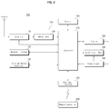
- FIG. 2 is a block diagram of the image display apparatus illustrated in FIG. 1 .
- the image display apparatus 100 may include a broadcasting receiver 105 , a memory 140 , a user input interface 150 , a sensor unit (not shown), a controller 170 , the display 180 , and an audio output unit 185 .
- the broadcasting receiver 105 may include a tuner unit 110 , a demodulator 120 , an external device interface 130 , and a network interface 135 .
- the broadcasting receiver 105 may include only the tuner unit 110 , the demodulator 120 , and the external device interface 130 . That is, the broadcasting receiver 105 may not include the network interface 135 .
- the tuner unit 110 selects a Radio Frequency (RF) broadcast signal corresponding to a channel selected by a user or an RF broadcast signal corresponding to each of pre-stored channels from among a plurality of RF broadcast signals received through an antenna (not shown), and downconverts the selected RF broadcast signal into an Intermediate Frequency (IF) signal or a baseband Audio/Video (A/V) signal.
- RF Radio Frequency
- the tuner unit 110 downconverts the selected RF broadcast signal into a digital IF signal.
- the tuner unit 110 downconverts the selected RF broadcast signal into an analog baseband A/V signal, CVBS/SIF. That is, the tuner unit 110 may process a digital broadcast signal or an analog broadcast signal.
- the analog baseband A/V signal, CVBS/SIF from the tuner unit 110 may be provided directly to the controller 170 .
- the tuner unit 110 may sequentially select a number of RF broadcast signals corresponding to all broadcast channels previously stored in the image display apparatus 100 by a channel add function from among a plurality of RF signals received through the antenna, and may downconvert the selected RF broadcast signals into IF signals or baseband A/V signals.
- the tuner unit 110 may include a plurality of tuners for receiving broadcast signals of a plurality of channels, or a single tuner for simultaneously receiving broadcast signals of a plurality of channels.
- the demodulator 120 receives the digital IF signal from the tuner unit 110 and demodulates the digital IF signal.
- the demodulator 120 may perform demodulation and channel decoding on the digital IF signal, thereby obtaining a stream signal TS.
- the stream signal TS may be a signal in which a video signal, an audio signal and/or a data signal are multiplexed.
- the stream signal may be input to the controller 170 and then subjected to demultiplexing and A/V signal processing.
- the controller 170 outputs the processed video and audio signals to the display 180 and the audio output unit 185 , respectively.
- the external device interface 130 may transmit and receive data to and from a connected external device (not shown) such as a set-top box.
- the external device interface 130 may include an A/V Input/Output (I/O) unit (not shown).
- the external device interface 130 may be connected to an external device, wirelessly or wiredly, such as a Digital Versatile Disk (DVD) player, a Blu-ray Disk (BD) player, a game console, a camera, a camcorder, a computer (e.g. a laptop computer), or a set-top box. Then, the external device interface 130 may transmit and receive signals to and from the external device.
- DVD Digital Versatile Disk
- BD Blu-ray Disk
- game console e.g. a camera
- camcorder e.g. a camcorder
- a computer e.g. a laptop computer
- set-top box e.g. a set-top box
- the A/V I/O unit may receive audio and video signals from an external device, and a wireless communication unit (not shown) may conduct short-range wireless communication with another electronic device.
- the external device interface 130 may exchange data with the nearby mobile terminal 600 through the wireless communication unit (not shown). Particularly, the external device interface 130 may receive device information, executed application information, an application image, and so on from the mobile terminal 600 in a mirroring mode.
- the network interface 135 serves as an interface between the image display apparatus 100 and a wired/wireless network such as the Internet.
- the network interface 135 may receive content or data from the Internet or from a Content Provider (CP) or a Network Provider (NP) over a network.
- CP Content Provider
- NP Network Provider
- the network interface 135 may include a wireless communication unit (not shown).
- the memory 140 may store programs necessary for the controller 170 to process signals and control, and may also store a processed audio, video, or data signal.
- the memory 140 may also temporarily store an audio, video or data signal received from the external device interface 130 .
- the memory 140 may store information about broadcast channels by the channel-add function.
- the memory 140 is shown in FIG. 2 as configured separately from the controller 170 , to which the present disclosure is not limited, the memory 140 may be incorporated into the controller 170 .
- the user input interface 150 transmits a signal received from the user to the controller 170 or transmits a signal received from the controller 170 to the user.
- the user input interface 150 may receive user input signals such as a power-on/off signal, a channel selection signal, and a screen setting signal from the remote controller 200 , provide the controller 170 with user input signals received from local keys (not shown), such as inputs of a power key, a channel key, a volume key, and a setting value, transmit a user input signal received from the sensor unit (not shown) that senses a user gesture to the controller 170 , or transmit a signal received from the controller 170 to the sensor unit (not shown).
- local keys not shown
- the controller 170 may demultiplex a stream signal received from the tuner unit 110 , the demodulator 120 , the network interface 135 , or the external device interface 130 into a number of signals, and process the demultiplexed signals into audio and video signals.
- the video signal processed by the controller 170 may be displayed as an image corresponding to the video signal on the display 180 .
- the video signal processed by the controller 170 may also be transmitted to an external output device through the external device interface 130 .
- the audio signal processed by the controller 170 may be output to the audio output unit 185 . Also, the audio signal processed by the controller 170 may be transmitted to an external output device through the external device interface 130 .
- controller 170 may include a Demultiplexer (DEMUX) and a video processor, which will be described later with reference to FIG. 3 .
- DEMUX Demultiplexer
- video processor which will be described later with reference to FIG. 3 .
- the controller 170 may provide overall control to the image display apparatus 100 .
- the controller 170 may control the tuner unit 110 to select an RF broadcast signal corresponding to a user-selected channel or a pre-stored channel.
- the controller 170 may control the image display apparatus 100 according to a user command received through the user input interface 150 or according to an internal program.
- the controller 170 may control the display 180 to display an image.
- the image displayed on the display 180 may be a Two-Dimensional (2D) or Three-Dimensional (3D) still image or video.
- the controller 170 may control a particular 2D object in the image displayed on the display 180 .
- the particular 2D object may be at least one of a linked Web page (e.g. from a newspaper or a magazine), an Electronic Program Guide (EPG), a menu, a widget, an icon, a still image, a video, or text.
- EPG Electronic Program Guide
- the controller 170 may locate the user based on an image captured by a camera unit (not shown). For example, the controller 170 may determine the distance (a z-axis coordinate) between the user and the image display apparatus 100 . In addition, the controller 170 may determine x-axis and y-axis coordinates corresponding to the position of the user on the display 180 .
- the display 180 generates drive signals by converting a processed video signal, a processed data signal, an On Screen Display (OSD) signal, and a control signal received from the controller 170 or a video signal, a data signal, and a control signal received from the external device interface 130 .
- OSD On Screen Display
- the display 180 may be various types of displays such as a Plasma Display Panel (PDP), a Liquid Crystal Display (LCD), an Organic Light-Emitting Diode (OLED) display, and a flexible display.
- the display 180 may also be a 3D display.
- the 3D display 180 may be classified into a glasses-free type and a glasses type.
- the display 180 may also be a touch screen that can be used not only as an output device but also as an input device.
- the audio output unit 185 may receive a processed audio signal from the controller 170 and output the received audio signal as voice.
- the camera unit (not shown) captures a user.
- the camera unit may include, but not limited to, a single camera. When needed, the camera unit may include a plurality of cameras.
- the camera unit may be embedded on the display 180 in the image display apparatus 100 , or may be separately configured. Image information captured by the camera unit may be provided to the controller 170 .
- the controller 170 may sense a user's gesture from a captured image received from the camera unit or from signals received from the sensor unit (not shown) alone or in combination.
- the power supply 190 supplies power across the whole image display apparatus 100 .
- the power supply 190 may supply power to the controller 170 which may be implemented as a System On Chip (SOC), the display 180 for displaying an image, the audio output unit 185 for outputting an audio signal, and so on.
- SOC System On Chip
- the power supply 190 may include a converter for converting Alternating Current (AC) power to Direct Current (DC) power, and a DC/DC converter for converting the level of DC power.
- AC Alternating Current
- DC Direct Current
- the remote controller 200 transmits a user input to the user input interface 150 .
- the remote controller 200 may operate based on various communication standards such as Bluetooth, RF communication, IR communication, Ultra WideBand (UWB), and ZigBee.
- the remote controller 200 may receive a video signal, an audio signal and/or a data signal from the user input interface 150 and may output the received signal as an image or sound.
- the above-described image display apparatus 100 may be a fixed or mobile digital broadcast receiver.
- the block diagram of the image display apparatus 100 illustrated in FIG. 2 is an exemplary embodiment of the present disclosure.
- the image display apparatus 100 is shown in FIG. 15 as having a number of components in a given configuration. However, the image display apparatus 100 may include fewer components or more components than those shown in FIG. 15 . Also, two or more components of the image display apparatus 100 may be combined into a single component or a single component thereof may be separated into two more components.
- the functions of the components of the image display apparatus 100 as set forth herein are illustrative in nature and may be modified, for example, to meet the requirements of a given application.
- FIG. 3 is a block diagram of the controller illustrated in FIG. 2 .
- the controller 170 may include a DEMUX 310 , a video processor 320 , a processor 330 , an OSD generator 340 , a mixer 345 , a Frame Rate Converter (FRC) 350 , and a formatter 360 according to an embodiment of the present invention.
- the controller 170 may further include an audio processor (not shown) and a data processor (not shown).
- the DEMUX 310 demultiplexes an input stream.
- the DEMUX 310 may demultiplex an MPEG-2 TS into a video signal, an audio signal, and a data signal.
- the input stream signal may be received from the tuner unit 110 , the demodulator 120 , or the external device interface 130 .
- the video processor 320 may process the demultiplexed video signal.
- the video processor 320 may include a video decoder 325 and a scaler 335 .
- the video decoder 325 decodes the demultiplexed video signal and the scaler 335 scales the resolution of the decoded video signal so that the video signal may be displayed on the display 180 .
- the video decoder 325 may be provided with decoders that operate in conformance to various standards.
- the video decoder 325 may include, for example, an MPEG-2 decode, an H.264 decode, a 3D video decoder for a color image a depth image, a decoder for multi-view images, and so on.
- the processor 330 may provide overall control to the image display apparatus 100 or the controller 170 .
- the processor 330 may control the tuner unit 110 to tune to an RF broadcasting corresponding to a user-selected channel or a pre-stored channel.
- the processor 330 may also control the image display apparatus 100 according to a user command received through the user input interface 150 or an internal program.
- the processor 330 may control data transmission through the network interface 135 or the external device interface 130 .
- the processor 330 may control operations of the DEMUX 310 , the video processor 320 , and the OSD generator 340 in the controller 170 .
- the OSD generator 340 generates an OSD signal autonomously or according to a user input.
- the OSD generator 340 may generate signals by which a variety of information is displayed as graphics or text on the display 180 , according to user input signals.
- the OSD signal may include various data such as a User Interface (UI), a variety of menus, widgets, and icons.
- UI User Interface
- the generated OSD signal may include a 2D or 3D object.
- the OSD generator 340 may generate a pointer to be displayed on the display 180 based on a pointing signal received from the remote controller 200 .
- the pointer may be generated from a pointing signal processor (not shown), which may reside in the OSD generator 340 .
- the pointing signal processor may be configured separately from the OSD generator 240 .
- the mixer 345 may mix the decoded video signal processed by the video processor 320 with the OSD signal generated from the OSD generator 340 .
- the mixed video signal is provided to the FRC 350 .
- the FRC 350 may change the frame rate of the input video signal or simply output the video signal without frame rate conversion.
- the formatter 360 may arrange left-eye and right-eye video frames of the frame rate-converted 3D image and may also output a synchronization signal Vsync to open the left or right lens of a 3D viewing device (not shown).
- the formatter 360 may change the format of an input video signal to a video signal to be displayed on the display.
- the formatter 360 may change the format of a 3D video signal to one of various 3D formats such as a side by side format, a top/down format, a frame sequential format, an interlaced format, and a checker format.
- the formatter 360 may convert a 2D video signal to a 3D video signal.
- the formatter 360 may detect edges or a selectable object from the 2D video signal and generate a 3D video signal with an object based on the detected edges or the selectable object by a 3D image generation algorithm.
- the 3D video signal may be separated into left-eye and right-eye image signals L and R.
- a 3D processor may further be provided at the rear end of the formatter 360 , for processing a signal to exert 3D effects.
- the 3D processor may adjust the brightness, tint, and color of a video signal.
- the 3D processor may process a video signal so that a near area appears clear and a far area appears obscure.
- the function of the 3D processor may be incorporated into the formatter 360 or the video processor 320 .
- the audio processor (not shown) of the controller 170 may process the demultiplexed audio signal.
- the audio processor may have a plurality of decoders.
- the audio processor (not shown) of the controller 170 may also adjust the bass, treble, and volume of the audio signal.
- the data processor (not shown) of the controller 170 may process the data signal obtained by demultiplexing the input stream signal. For example, if the demultiplexed data signal is a coded data signal, the data processor may decode the coded data signal.
- the coded data signal may be an EPG which includes broadcasting information specifying the start time, end time, and the like of a scheduled broadcast program of each channel.
- the block diagram of the controller 170 illustrated in FIG. 3 is purely exemplary. Depending upon the specifications of the controller 170 in actual implementation, the components of the controller 170 may be combined or omitted or new components may be added.
- the FRC 350 and the formatter 360 may be configured as separate modules or as a single module, outside the controller 170 .
- FIG. 4A illustrates a method for controlling the remote controller illustrated in FIG. 2 .
- FIG. 4A illustrates a pointer 205 representing movement of the remote controller 200 , displayed on the display 180 .
- the user may move or rotate the remote controller 200 up and down, side to side ((b) of FIG. 4A ), and back and forth ((c) of FIG. 4A ).
- the pointer 205 displayed on the display 180 corresponds to movement of the remote controller 200 . Since the pointer 205 moves in accordance with the movement of the remote controller 200 in a 3D space, the remote controller 200 may be referred to as a spatial remote controller or a 3D pointing device.
- a sensor of the remote controller 200 detects the movement of the remote controller 200 and transmits motion information corresponding to the result of the detection to the image display apparatus. Then, the image display apparatus may determine the movement of the remote controller 200 based on the motion information received from the remote controller 200 , and calculate the coordinates of a target point to which the pointer 205 should be shifted in accordance with the movement of the remote controller 200 based on the result of the determination. The image display apparatus then displays the pointer 205 at the calculated coordinates.
- the up, down, left and right movements of the remote controller 200 may be ignored. That is, when the remote controller 200 moves away from or approaches the display 180 , only the back and forth movements of the remote controller 200 are sensed, while the up, down, left and right movements of the remote controller 200 are ignored. Unless the predetermined button is pressed in the remote controller 200 , the pointer 205 moves in accordance with the up, down, left or right movement of the remote controller 200 .
- the speed and direction of the pointer 205 may correspond to the speed and direction of the remote controller 200 .
- FIG. 4B is a block diagram of the remote controller illustrated in FIG. 2 .
- the remote controller 200 may include a wireless communication module 420 , a user input unit 430 , a sensor unit 440 , an output unit 450 , a power supply 460 , a memory 470 , and a controller 480 .
- the wireless communication module 420 transmits signals to and/or receives signals from one of image display apparatuses according to embodiments of the present disclosure.
- One of the image display apparatuses according to embodiments of the present disclosure, that is, the image display apparatus 100 will be taken as an example.
- the remote controller 200 may include an RF module 421 for transmitting RF signals to and/or receiving RF signals from the image display apparatus 100 according to an RF communication standard. Further, the remote controller 200 may include an IR module 423 for transmitting IR signals to and/or receiving IR signals from the image display apparatus 100 according to an IR communication standard.
- the remote controller 200 may transmit a signal carrying information about movement of the remote controller 200 to the image display apparatus 100 through the RF module 421 .
- the remote controller 200 may receive signals from the image display apparatus 100 through the RF module 421 .
- the remote controller 200 may transmit commands, such as a power on/off command, a channel switching command, or a sound volume change command, to the image display apparatus 100 through the IR module 423 , as needed.
- the user input unit 430 may include a keypad, a plurality of buttons, a touch pad, or a touch screen. The user may enter commands to the image display apparatus 100 by manipulating the user input unit 430 . If the user input unit 430 includes a plurality of hard-key buttons, the user may input various commands to the image display apparatus 100 by pressing the hard-key buttons. If the user input unit 430 includes a touch screen displaying a plurality of soft keys, the user may input various commands to the image display apparatus 100 by touching the soft keys.
- the user input unit 430 may also include various input tools other than those set forth herein, such as a scroll key and/or a jog key, which should not be construed as limiting the present disclosure.
- the sensor unit 440 may include a gyro sensor 441 and/or an acceleration sensor 443 .
- the gyro sensor 441 may sense the movement of the remote controller 200 .
- the gyro sensor 441 may sense motion information about the remote controller 200 in X-, Y-, and Z-axis directions.
- the acceleration sensor 443 may sense the moving speed of the remote controller 200 .
- the sensor unit 440 may further include a distance sensor for sensing the distance between the remote controller 200 and the display 180 .
- the output unit 450 may output a video and/or audio signal corresponding to a manipulation of the user input unit 430 or a signal transmitted by the image display apparatus 100 .
- the user may easily identify whether the user input unit 430 has been manipulated or whether the image display apparatus 100 has been controlled based on the video and/or audio signal output from the output unit 450 .
- the output unit 450 may include an LED module 451 which is turned on or off whenever the user input unit 430 is manipulated or whenever a signal is received from or transmitted to the image display apparatus 100 through the wireless communication module 420 , a vibration module 453 which generates vibrations, an audio output module 455 which outputs audio data, or a display module 457 which outputs an image.
- an LED module 451 which is turned on or off whenever the user input unit 430 is manipulated or whenever a signal is received from or transmitted to the image display apparatus 100 through the wireless communication module 420
- a vibration module 453 which generates vibrations
- an audio output module 455 which outputs audio data
- a display module 457 which outputs an image.
- the power supply 460 supplies power to the remote controller 200 . If the remote controller 200 is kept stationary for a predetermined time or longer, the power supply 460 may, for example, cut off supply of power to the remote controller 200 in order to save power. The power supply 460 may resume supply of power if a specific key on the remote controller 200 is manipulated.
- the memory 470 may store various programs and application data for controlling or operating the remote controller 200 .
- the remote controller 200 may wirelessly transmit signals to and/or receive signals from the image display apparatus 100 in a predetermined frequency band through the RF module 421 .
- the controller 480 of the remote controller 200 may store information regarding the frequency band used for the remote controller 200 to wirelessly transmit signals to and/or wirelessly receive signals from the paired image display apparatus 100 in the memory 470 and may then refer to this information for use at a later time.
- the controller 480 provides overall control to the remote controller 200 .
- the controller 480 may transmit a signal corresponding to a key manipulation detected from the user input unit 430 or a signal corresponding to motion of the remote controller 200 , as sensed by the sensor unit 440 , to the image display apparatus 100 through the wireless communication module 420 .
- the user input interface 150 of the image display apparatus 100 may include a wireless communication module 411 which wirelessly transmits signals to and/or wirelessly receives signals from the remote controller 200 , and a coordinate calculator 415 which calculates coordinates representing the position of the remote controller 200 on the display screen, which is to be moved in accordance with the movement of the remote controller 200 .
- the user input interface 150 may wirelessly transmit RF signals to and/or wirelessly receive RF signals from the remote controller 200 through an RF module 412 .
- the user input interface 150 may wirelessly receive IR signals from the remote controller 200 through an IR module 413 according to the IR communication standard.
- the coordinate calculator 415 may receive motion information regarding the movement of the remote controller 200 through the wireless communication module 411 and may calculate coordinates (x, y) representing the position of the pointer 205 on a screen of the display 180 by correcting the motion information for possible errors or user hand tremor.
- a signal received in the image display apparatus 100 from the remote controller 200 through the user input interface 150 may be transmitted to the controller 170 . Then, the controller 170 may acquire information regarding the movement of the remote controller 200 and information regarding a key manipulation detected from the remote controller 200 from the signal received from the remote controller 200 , and may control the image display apparatus 100 based on the acquired information.
- the remote controller 200 may calculate the coordinates of a position to which the pointer is to be shifted in correspondence with its movement and output the coordinates to the user input interface 150 of the image display apparatus 100 .
- the user input interface 150 may transmit information about the pointer coordinates which was not corrected for possible errors or user hand tremor to the controller 170 .
- the coordinate calculator 415 may reside in the controller 170 , instead of the user input interface 150 .
- FIG. 5 is a block diagram of the mobile terminal illustrated in FIG. 1 .
- a mobile terminal 600 may include a wireless communication unit 610 , an A/V input unit 620 , a user input unit 630 , a sensor unit 640 , an output unit 650 , a memory 660 , an interface 625 , a controller 670 , and a power supply 690 .
- the wireless communication unit 610 may include a broadcasting reception module 611 , a mobile communication module 613 , a wireless Internet module 615 , an audio communication unit 617 , and a Global Positioning System (GPS) module 619 .
- GPS Global Positioning System
- the broadcasting reception module 611 receives at least one of a broadcast signal or broadcasting-related information on a broadcast channel from an external broadcasting management server.
- the broadcast channel may be any of a satellite channel, a terrestrial channel, and so on.
- the broadcast signal and/or broadcasting-related information received at the broadcasting reception module 611 may be stored in the memory 660 .
- the mobile communication module 613 transmits a radio signal to and receives a radio signal from at least one of a Base Station (BS), an external terminal, or a server over a mobile communication network.
- the radio signal may include a voice call signal, a video call signal, or text/other various types of data involved in multimedia message transmission and reception.
- the wireless Internet module 615 is a built-in or external module for providing wireless Internet connectivity to the mobile terminal 600 .
- the wireless Internet module 615 may operate in conformance to Wireless Fidelity (WiFi) or WiFi Direct.
- the audio communication unit 617 is used for audio communication.
- the audio communication unit 617 may output a sound by adding predetermined information data to audio data to be output in an audio communication mode. Further, the audio communication unit 617 may extract predetermined information data from a sound received from the outside in the audio communication mode.
- Bluetooth Radio Frequency Identification
- IrDA Infrared Data Association
- UWB Ultra WideBand
- ZigBee ZigBee
- the GPS module 619 receives location information from a plurality of GPS satellites.
- the A/V input unit 620 is used to receive an audio signal or a video signal and may include a camera 621 and a microphone 623 .
- the user input unit 630 generates key input data that the user inputs to control the operation of the mobile terminal 600 .
- the user input unit 630 may include a keypad, a dome switch, a (resistive/capacitive) touch pad, and so on.
- a touch pad is layered with a display 680 , the resulting structure may be referred to as a touch screen.
- the sensor unit 640 senses the current state of the mobile terminal 600 , such as the open or closed state, position, or user touch of the mobile terminal 600 and generates a sensing signal to control the operation of the mobile terminal 600 according to the sensed state.
- the sensor unit 640 may include a proximity sensor 641 , pressure sensor 643 , and a motion sensor 645 .
- the motion sensor 645 senses the position or motion of the mobile terminal 600 using an accelerometer sensor, a gyro sensor, a gravity sensor, or the like. Particularly, the gyro sensor measures an angular velocity and thus senses a rotated direction with respect to a reference direction.
- the output unit 650 may include the display 680 , an audio output module 653 , an alarm emitter 655 , and a haptic module 657 .
- the display 680 displays information processed in the mobile terminal 600 .
- the display 680 may be used not only as an output device but also as an input device capable of receiving information by a user's touch.
- the audio output unit 653 outputs audio data received from the wireless communication unit 610 or stored in the memory 660 .
- the audio output unit 653 may include a speaker, a buzzer, and the like.
- the alarm emitter 655 outputs a signal notifying occurrence of an event to the mobile terminal 600 .
- the event notification signal may be output in the form of vibrations.
- the haptic module 657 generates various tactile effects that a user can feel.
- a major example of the tactile effects is vibrations.
- the memory 660 may store programs required for processing and controlling in the controller 670 or temporarily store input or output data (e.g. a phone book, messages, still images, videos, etc.).
- input or output data e.g. a phone book, messages, still images, videos, etc.
- the interface 625 interfaces between the mobile terminal 600 and all external devices connected to the mobile terminal 600 .
- the interface 625 may receive data or power from such an external device and transfer the data or power to each component of the mobile terminal 600 .
- the interface 625 may transmit data from the mobile terminal 600 to the external device.
- the controller 670 typically provides overall control to the mobile terminal 600 by controlling the operation of each component.
- the controller 670 controls and processes voice call, data communication, video call, and so on.
- the controller 670 may include a multimedia player module 681 for playing multimedia.
- the multimedia player module 681 may be configured in hardware inside the controller 670 or in software separately from the controller 670 .
- the power supply 690 may receive power from an external power source or an internal power source and supply power to the other components of the mobile terminal 600 under the control of the controller 670 .
- the block diagram of the mobile terminal 600 illustrated in FIG. 5 is purely exemplary. Depending upon the specifications of the mobile terminal 600 in actual implementation, the components of the mobile terminal 600 may be combined or omitted or new components may be added. That is, when needed, two or more components may be incorporated into a single component, or one component may be separated into two or more components. Further, the function of each block is presented to describe embodiments of the present disclosure, and its specific operation or device does not limit the scope and spirit of the present disclosure.
- FIG. 6 is a flowchart illustrating an exemplary method for operating an image display apparatus and a mobile terminal according to an embodiment of the present disclosure
- FIGS. 7A to 14I are views referred to for describing the operation method illustrated in FIG. 6 .
- the controller 170 of the image display apparatus 100 determines whether a mirroring input has been received (S 605 ).
- the controller 170 of the image display apparatus 100 may control to display an application list 709 including a plurality of application items on a part of the display 180 , as illustrated in FIG. 7B .
- the application list 709 may include the plurality of application items, and is shown in FIG. 7B as including a mirroring application item 715 a.
- the controller 170 of the image display apparatus 100 may control execution of mirroring with the preset mobile terminal 600 .
- the image display apparatus 100 may transmit a pairing request signal to the mobile terminal 600 , and the mobile terminal 600 may reply to the image display apparatus 100 with a pairing response signal.
- the image display apparatus 100 may complete pairing with the mobile terminal based on the pairing response signal, thereby establishing a wireless connection with the mobile terminal 600 .
- the mobile terminal 600 may transmit a pairing request signal to the mobile terminal 600 , and the image display apparatus 100 may reply to the mobile terminal 600 with a pairing response signal.
- the mobile terminal 600 may complete pairing with the image display apparatus 100 based on the pairing response signal, thereby establishing a wireless connection with the image display apparatus 100 .
- the controller 170 of the image display apparatus 100 may determine that the mirroring input has been received.
- the controller 170 of the image display apparatus 100 may determine that the mirroring input has been received.
- the mobile terminal 600 may transmit, as a mirrored image, an image displayed on the display 680 of the mobile terminal 600 to the image display apparatus 100 (S 610 ).
- the controller 170 of the image display apparatus 100 may receive the mirrored image through the interface 135 (S 611 ), and may control to display the received mirrored image on the display 180 (S 620 ).
- the mobile terminal 600 may transmit additional black images added to the left and right sides of the image 710 displayed on the display 680 of the mobile terminal 600 according to the resolution or aspect ratio of the image display apparatus 100 .
- the controller 170 of the image display apparatus 100 may receive the additional black images added to the left and right sides of the image 710 along with the image 710 displayed on the display 680 of the mobile terminal 600 , and control to display the additional black images and the mirrored image 720 in areas Ara, Arb, and Arc of the display 180 .
- FIG. 7C illustrates an example of displaying additional black images Bla and Blb on the left and right sides of the mirrored image 720 .
- the controller 170 of the image display apparatus 100 may display the mirrored image 729 without signal processing of the input image, such as image editing, as illustrated in FIG. 7C .
- the mirrored image 720 may be displayed after image editing and the like.
- an additional black image Blc is displayed in the area Ar 2
- the mirrored image 720 is displayed in the area Ar 1 to the right of the area Ar 2 .
- the controller 170 of the image display apparatus 100 may extract the additional black images Bla and Blb from the input image by an area detection technique, generate the additional black image Blc by combining the left and right additional black images Bla and Blc, and control to display the additional black image Blc in the area Ar 2 , and may control to display the mirrored image 720 in the area Ar 1 to the right of the area Ar 2 .
- the controller 170 of the image display apparatus 100 may distinguish an image display area from a non-display area in the mirrored image 720 received from the mobile terminal 600 by the area detection technique, and control to display the image display area of the mirrored image 720 in an area of the display 180 .
- the controller 170 of the image display apparatus 100 may control to display only the mirrored image 720 except for the additional black images Bla and Blb out of the image received from the mobile terminal 600 .
- the controller 170 of the image display apparatus 100 may control to display a zoomed-in image of a first area of the mirrored image (S 640 ).
- the partial zoom-in display input for the mirrored image may be generated by manipulation of a zoom-in display button of the remote controller.
- a partial zoom-in display button 200 x of the remote controller 200 is manipulated as illustrated in FIG. 7C , it may be controlled that only the zoomed-in image 730 is displayed in the area Ar 2 except for the area Ar 1 displaying the mirrored image 720 , as illustrated in FIG. 7E . Accordingly, a zoomed-in image of a partial area of a mirrored image may be displayed simply on the display 180 .
- the controller 170 of the image display apparatus 100 may control to display the indicator IND for area selection in the image area 725 , and control to display a zoomed-in image of the image area 725 on the display 180 .
- the controller 170 of the image display apparatus 100 may distinguish the image area 725 from the text area 727 in the mirrored image 720 by area detection, and may control to display the indicator IND in the image area 725 by default.
- the controller 170 of the image display apparatus 100 may control zoom-in, zoom-out, or shift of the indicator IND according to an input signal of the remote controller 200 .
- the zoomed-in image 730 displayed in the area Ar 2 of the image display apparatus 100 may be an image scaled-up by the controller 170 of the image display apparatus 100 .
- the zoomed-in image 730 displayed in the area Ar 2 of the image display apparatus 100 may be an image that the mobile terminal 600 has scaled up and transmitted.
- the zoomed-in image 730 displayed in the area Ar 2 of the image display apparatus 100 may be transmit a zoomed-in image transmission request for the image area of the mirrored image to the mobile terminal 600 , and control to display a zoomed-in image received from the mobile terminal 600 on the display 180 .
- the zoomed-in image 730 displayed in the area Ar 2 of the image display apparatus 100 may be an image that an external server has provided.
- the controller 170 of the image display apparatus 100 may request a zoomed-in image of the image displayed on the mobile terminal 600 to the external server, using a URL of the external server, and control to display the zoomed-in image received from the external server.
- the external server may be a server that streams a still image or a video.
- the external server may be a Web portable server, a video providing server, or the like.
- the controller 170 of the image display apparatus 100 may play the zoomed-in image 730 and control to display a played image 740 in the area Ar 1 , as illustrated in FIG. 7G .
- FIG. 7F illustrates an example of selecting the play icon 732 by the pointer 205 representing movement of the remote controller 200 .
- the controller 170 of the image display apparatus 100 may request a play request to the mobile terminal 600 , receive an image played in the mobile terminal 600 , and control play and display of a zoomed-in image of the played image.
- the controller 170 of the image display apparatus 100 may request a zoomed-in played image to be played on the image display apparatus 100 having a higher resolution that the mobile terminal 600 to an external server (not shown), using a URL of the external server, and control to display the zoomed-in played image received from the external server.
- a played image 746 is displayed in the area Ar 1 .
- a played image 742 is also displayed on the display 680 of the mobile terminal 600 .
- a status bar 741 indicating a play progress status may further be displayed in addition to the played image 742 .
- the played images may be displayed respectively, as illustrated in FIG. 7G .
- the controller 170 of the image display apparatus 100 may control disappearance of the displayed mirrored image and full-screen display of the zoomed-in image on the entirety of the display 180 , as illustrated in FIG. 7H (S 660 ).
- FIG. 7H illustrates an example in which the mirrored image 720 displayed in the area Ar 2 disappears, the zoomed-in image displayed in the area Ar 2 is enlarged, and a largest zoomed-in image 740 a is displayed in full screen on the entirety of the display 180 . Therefore, the user may be more immersed in the zoomed-in image 740 a.
- the controller 170 of the image display apparatus 100 may control the image area of the mirrored image to disappear and, instead, control the text area to be displayed, as illustrated in FIG. 7I .
- the played image 740 is still displayed.
- the displayed text is zoomed in, or additional undisplayed text may be included.
- the area Ar 2 may be dedicated to display of the zoomed-in played image 740
- the area Ar 1 may be dedicated to display of the text area.
- the method of FIG. 7H is applicable for displaying a zoomed-in image before a played image is displayed. That is, when a zoomed-in image is displayed in the area AR 2 , it is possible to remove an image area and instead, to display only a text area in the area Ar 1 .
- the controller 170 of the image display apparatus 100 may control to display an icon 811 for zoom-in display according to a predetermined input, as illustrated in FIG. 8A .
- the controller 170 of the image display apparatus 100 may control to display the zoomed-in image 730 of the first area in the mirrored image in the area Ar 1 of the display 180 , as illustrated in FIG. 8B .
- the mirrored image 720 may be displayed in the area Ar 1 .
- the controller 170 of the image display apparatus 100 may control to display the zoomed-image 730 as it is and display of the mirrored image changed according to the mode of the mobile terminal 600 .
- an image 710 b displayed on the mobile terminal 600 includes only an image area without a text area. Therefore, a mirrored image 720 b displayed on the image display apparatus 100 may include only an image area without a text area. Therefore, the size of the display area of the mirrored image may be decreased, as illustrated in FIG. 8C .
- the zoomed-in image 730 may still be displayed in the area Ar 2 .
- the zoomed-in image 730 may still be displayed in the area Ar 2 .
- the size of the display area of the mirrored image may be increased and thus the text area may also be displayed.
- the controller 170 of the image display apparatus 100 may control the display position of a mirrored image to be changed according to a shift input for the mirrored image.
- the controller 170 of the image display apparatus 100 may control the display position of the mirrored image to be changed.
- FIG. 9A illustrates an example of displaying the zoomed-in image 730 in the area Ar 2 on the left side of the display 180 , and the mirrored image 720 in the area Ar 1 on the right side of the display 180 .
- the controller 170 of the image display apparatus 100 may change the display positions of the zoomed-in image 730 and the mirrored image 720 in response to input of a directional key or the like of the remote controller 200 .
- the zoomed-in image 730 may be displayed in an area Ar 4 on the right side of the display 180
- the mirrored image 720 may be displayed in an area Ar 3 on the left side of the display 180 . Therefore, the user may view an intended image in an intended area.
- the controller 170 of the image display apparatus 100 may control to display a mirrored image and a zoomed-in image differently in the portrait mode and a normal mode.
- FIG. 10A illustrates an example of displaying the zoomed-in image 730 in the area Ar 2 and the mirrored image 720 in the area Ar 1 in the portrait mode.
- FIG. 10B illustrates an example of displaying a mirrored image 1020 in a bottom right part, and positioning the indicator IND on the entire area of the mirrored image 1020 .
- the indicator IND is positioned on the entire area including the additional images.
- the zoomed-in image 720 obtained by scaling up the entire area of the mirrored image 1020 may be displayed on the display 180 .
- the additional black images may be displayed added in left and right areas Ara and Arb of the mirrored image 1020 displayed in an area Arc.
- user convenience may be increased by providing these various UIs.
- FIG. 11A illustrates an example of displaying the zoomed-in image 730 in the area AR 2 and the mirrored image 720 in the area Ar 1 .
- the controller 170 of the image display apparatus 100 may control to display an icon 1111 representing fixing on an image area of the mirrored image, as illustrated in FIG. 11B . Therefore, the fixed image area 725 of the mirrored image 720 may be zoomed in on so that the zoomed-in image 730 may be displayed in the area Ar 2 .
- controller 170 of the image display apparatus 170 may apply different settings to manipulation of the remote controller 200 , for display of a zoomed-in image and display of a mirrored image.
- an image display area of the mirrored image 720 that is, a third area POSc can be dragged by manipulation of the remote controller 200 , whereas a first area POSa of the zoomed-in area 730 and a second area POSb of the mirrored image 720 cannot be dragged by manipulation of the remote controller 200 .
- the controller 170 of the image display apparatus 100 controls the size (particularly, height) of the indicator IND to be changed, but a text area in the second area POSb of the mirrored image 720 may be scrolled by manipulation of the wheel key.
- the controller 170 of the image display apparatus 100 may detect the mirrored image 720 except for the additional images in the areas Ara and Arb by the area detection technique during display of the additional black images, as illustrated in FIG. 12C . As illustrated in FIG. 7E , it may be controlled that the mirrored image 720 is displayed in the right area, Ar 1 .
- the controller 170 of the image display apparatus 100 may detect areas in the mirrored image. If an image area is included in the mirrored image, the controller 170 of the image display apparatus 100 may control to display the indicator for selecting a first area in the image area.
- the controller 170 of the image display apparatus 100 may control to display the indicator IND at the top end.
- the controller 170 of the image display apparatus 100 may detect the location of the mirrored image 1320 and control to display the indicator IND at the center, as illustrated in FIG. 13 .
- the controller 170 of the image display apparatus 100 may control to display an indicator for selecting a first area on one of the thumbnail images, and control to display a zoomed-in image of the thumbnail image on which the indicator is displayed.
- the controller 170 of the image display apparatus 100 may control to display an indicator for selecting a first area, on a thumbnail image of a video among a plurality of thumbnail images, and may control to display a zoomed-in image of the thumbnail image of the video on which the indicator is displayed, on the display 180 .
- the controller 170 of the image display apparatus 100 may control transmission of a video play request to the mobile terminal 600 , reception of a video played in correspondence with the thumbnail image, and zoomed-in display of the received video.
- the controller 170 of the image display apparatus 100 may control to display the application list 709 including a plurality of application items on a part of the display 180 , as illustrated in FIG. 14B .
- the application list 709 may include a plurality of application items.
- the application list 709 is shown in FIG. 14B as including the mirroring application item 715 a , by way of example.
- the controller 170 of the image display apparatus 100 may control mirroring with the preset mobile terminal 600 .
- the controller 170 of the image display apparatus 100 may determine that the mirroring input has been received.
- the controller 170 of the image display apparatus 100 may determine that the mirroring input has been received.
- the mobile terminal 600 may transmit, as a mirrored image, an image displayed on the display 680 of the mobile terminal 600 to the image display apparatus 100 .
- the controller 170 of the image display apparatus 100 may receive the mirrored image through the interface 135 , and may control to display the received mirrored image on the display 180 .
- the mobile terminal 600 may transmit additional black images added to the left and right sides of an image 1410 displayed on the display 680 of the mobile terminal 600 according to the resolution or aspect ratio of the image display apparatus 100 .
- the controller 170 of the image display apparatus 100 may receive the additional black images added to the left and right sides of the image 710 along with the image 710 displayed on the display 680 of the mobile terminal 600 , and control to display the additional black images and a mirrored image 1420 in areas Ara, Arb, and Arc of the display 180 .
- FIG. 14C illustrates an example of displaying additional black images on the left and right sides of the mirrored image 1420 .
- the controller 170 of the image display apparatus 100 may display the mirrored image 1420 without signal processing of the input image, such as image editing, as illustrated in FIG. 14C .
- the mirrored image 720 may be displayed after image editing and the like.
- the controller 170 of the image display apparatus 100 may extract black areas from an input image by an area detection technique, generate an additional black image by combining the left and right black areas, and control to display the additional black image in the area Ar 2 , and may control to display the mirrored image 1420 in the right area Ar 1 .
- the controller 170 of the image display apparatus 100 may distinguish an image display area from a non-display area in the mirrored image by the area detection technique, and control to display the image display area of the mirrored image shifted to an area of the display 180 .
- the controller 170 of the image display apparatus 100 may control to display only the mirrored image 1420 except for the additional black images in the image received from the mobile terminal 600 .
- the image 1410 displayed on the display 680 of the mobile terminal 600 may be a gallery screen including a plurality of thumbnail images, as illustrated in FIG. 14C .
- the gallery screen may include thumbnail images of still images such as photo images and thumbnail images of videos.
- the controller 170 of the image display apparatus 100 may control to display a zoomed-in image of a first area of the mirrored image.
- the partial zoom-in display input for the mirrored image may be generated by manipulation of a zoom-in display button of the remote controller.
- the partial zoom-in display button 200 x of the remote controller 200 is manipulated with the mirrored image 1420 displayed as illustrated in FIG. 14C , it may be controlled that only a zoomed-in image 1430 is displayed in the area Ar 2 except for the area Ar 1 displaying the mirrored image 1420 , as illustrated in FIG. 14E . Accordingly, a zoomed-in image of a partial area of a mirrored image may be displayed simply on the display 180 .
- the controller 170 of the image display apparatus 100 may control to display the indicator IND for selection of the first area on a thumbnail image 1425 , and control to display a zoomed-in image 1430 of the thumbnail image of the video on which the indicator IND is displayed, in the area Ar 2 of the display 180 , as illustrated in FIG. 14E .
- the controller 170 of the image display apparatus 100 may distinguish thumbnail images of still images from thumbnail images of videos by area detection of the mirrored image 1420 , and may control to display the indicator IND on the thumbnail image 1425 of the video by default.
- the controller 170 of the image display apparatus 100 may control zoom-in, zoom-out, or shift of the indicator IND according to an input signal of the remote controller 200 .
- the zoomed-in image 1430 displayed in the area Ar 2 of the image display apparatus 100 may be an image scaled-up by the controller 170 of the image display apparatus 100 .
- the zoomed-in image 1430 displayed in the area Ar 2 of the image display apparatus 100 may be an image that the mobile terminal 600 has scaled up and transmitted.
- a zoomed-in image transmission request for the image area of the mirrored image to the mobile terminal 600 , and control to display a zoomed-in image received from the mobile terminal 600 on the display 180 .
- the controller 170 of the image display apparatus 100 may control to display a zoomed-in played image 1440 in the area Ar 2 , as illustrated in FIG. 14G .
- FIG. 14F illustrates an example of selecting the play icon 1432 using the pointer 205 representing movement of the remote controller 200 .
- the controller 170 of the image display apparatus 100 may transmit a play request for a video file to the mobile terminal 600 , receive a video played in correspondence with the thumbnail image of the video from the mobile terminal 600 , and control zoomed-in display of the received video.
- FIG. 14G as the played image 1440 is displayed in the area Ar 2 , an image in the mirrored image 1420 in the area Ar 1 is also played, and thus displayed as a played image 1423 in the area Ar 1 . Further, a played image 1413 is also displayed on the display 680 of the mobile terminal 600 .
- a status bar 441 indicating a play progress status may further be displayed in addition to the played image 1440 .
- the played images are displayed respectively as illustrated in FIG. 14G .
- the controller 170 of the image display apparatus 100 may control the displayed mirrored image to disappear and control full-screen display of a zoomed-in image 1440 a on the entirety of the display 180 , as illustrated in FIG. 14H .
- FIG. 14H illustrates an example in which the mirrored image 1420 displayed in the area Ar 2 disappears, the zoomed-in image 1440 displayed in the area Ar 2 is scaled up, and thus the largest zoomed-in image 1440 a is displayed in full screen on the entirety of the display 180 . Therefore, the user may be more immersed in the zoomed-in image 1440 a.
- the controller 170 of the image display apparatus 100 may control the thumbnail image 1423 of the video in the mirrored image to disappear.
- the played image 440 is still displayed.
- the controller 170 of the image display apparatus 100 may control to display the indicator IND on the first thumbnail image 1451 among the plurality of thumbnail images in the mirrored image 1420 .
- the controller 170 of the image display apparatus 100 may control to display a zoomed-in image 1450 of the thumbnail image 1451 highlighted by the indicator IND. Accordingly, the legibility of a thumbnail image is increased during search on a gallery screen of the mobile terminal 600 .
- an image display apparatus includes a display, an interface to exchange data with a mobile terminal, and a controller to, when the mobile terminal is mirrored on the image display apparatus, control to display a mirrored image corresponding to an image displayed on the display of the mobile terminal on the display, and upon receipt of a zoom-in display input for a first area of the mirrored image, controlling display of a zoomed-in image of the first area of the mirrored image on the display.
- a zoomed-in image of a partial area may be simply displayed during mirroring between the mobile terminal and the image display apparatus.
- the mirrored image includes an image area and a text area
- an indicator for selection of the first area is displayed on the image area
- a zoomed-in image of the image area is displayed on the display. In this manner, an image may be displayed zoomed-in.
- a video played in the mobile terminal may be displayed on a zoomed-in screen in the image display apparatus.
- the mirrored image includes a plurality of thumbnail images
- the indicator for selection of the first area is displayed on one of the thumbnail images, and a zoomed-in image of the thumbnail image on which the indicator is displayed on the display.
- the thumbnail image may be displayed zoomed-in.
- a zoomed-in image is played.
- a video may be displayed zoomed-in.
- the mirrored image disappears and the zoomed-in image is displayed in full screen on the display. Accordingly, a user may be more immersed in the zoomed-in image.
- the mirrored image is divided into an image display area and a non-display area, and a zoomed-in display for the first area being a part of the mirrored image is received, the image display area of the mirrored image may be displayed shifted to an area of the display.
- the non-display area may be used for another usage, for example, display of a zoomed-in image.
- the mobile terminal is switched from landscape mode to portrait mode or vice versa, it is controlled that the zoomed-in image is still displayed and the mirrored image is changed according to the mode of the mobile terminal.
- the zoomed-in image may be displayed continuously, that is, seamless display of the zoomed-in image is possible.
- the mirrored image includes a plurality of thumbnail images
- an indicator for selection of a first area is displayed on one of the thumbnail images
- a zoomed-in image of the thumbnail image on which the indicator is displayed is displayed on the display. Therefore, the thumbnail image may be displayed zoomed-in.
- the mirrored image is a gallery image of the mobile terminal, it is controlled that an indicator for selecting a first area is displayed on a thumbnail image of a video among a plurality of thumbnail images, and a zoomed-in image of the thumbnail image of the video on which the indicator is displayed is displayed on the display 180 .
- the thumbnail image of the video may simply be displayed zoomed in.
- an image display apparatus includes a display, an interface to exchange data with a mobile terminal, and a controller to, upon receipt of a partial zoom-in display input in a state where the mobile terminal is mirrored on the image display apparatus, control to display a zoomed-in image of a partial area of a mirrored image received from the mobile terminal on the display.
- a zoomed-in image of a partial area may be simply displayed during mirroring between the mobile terminal and the image display apparatus.
- the method for operating an image display apparatus or a mobile terminal may be implemented as code that can be written on a computer-readable recording medium and thus read by a processor in the image display apparatus or the mobile terminal.
- the computer-readable recording medium may be any type of recording device in which data is stored in a computer-readable manner. Examples of the computer-readable recording medium include a ROM, a RAM, a CD-ROM, a magnetic tape, a floppy disc, an optical data storage, and a carrier wave such as data transmission over the Internet.
- the computer-readable recording medium can be distributed over a plurality of computer systems connected to a network so that computer-readable code is written thereto and executed therefrom in a decentralized manner.
Landscapes
- Engineering & Computer Science (AREA)
- Theoretical Computer Science (AREA)
- Multimedia (AREA)
- Signal Processing (AREA)
- General Engineering & Computer Science (AREA)
- Human Computer Interaction (AREA)
- Physics & Mathematics (AREA)
- General Physics & Mathematics (AREA)
- Business, Economics & Management (AREA)
- Marketing (AREA)
- Computer Networks & Wireless Communication (AREA)
- Controls And Circuits For Display Device (AREA)
Abstract
Description
Claims (14)
Applications Claiming Priority (2)
| Application Number | Priority Date | Filing Date | Title |
|---|---|---|---|
| KR10-2017-0078040 | 2017-06-20 | ||
| KR1020170078040A KR102350933B1 (en) | 2017-06-20 | 2017-06-20 | Image display apparatus |
Publications (2)
| Publication Number | Publication Date |
|---|---|
| US20180364881A1 US20180364881A1 (en) | 2018-12-20 |
| US10963151B2 true US10963151B2 (en) | 2021-03-30 |
Family
ID=64657351
Family Applications (1)
| Application Number | Title | Priority Date | Filing Date |
|---|---|---|---|
| US16/012,122 Active 2038-07-17 US10963151B2 (en) | 2017-06-20 | 2018-06-19 | Image display apparatus |
Country Status (5)
| Country | Link |
|---|---|
| US (1) | US10963151B2 (en) |
| EP (1) | EP3643073A4 (en) |
| KR (1) | KR102350933B1 (en) |
| CN (1) | CN111034207B (en) |
| WO (1) | WO2018236103A1 (en) |
Families Citing this family (12)
| Publication number | Priority date | Publication date | Assignee | Title |
|---|---|---|---|---|
| KR102598082B1 (en) * | 2016-10-28 | 2023-11-03 | 삼성전자주식회사 | Image display apparatus, mobile device and operating method for the same |
| CN111831243A (en) | 2019-04-18 | 2020-10-27 | 三星电子株式会社 | Display device, user terminal device, and device control method |
| CN112968991B (en) * | 2019-06-20 | 2022-07-29 | 华为技术有限公司 | Input method, electronic equipment and screen projection system |
| WO2021070976A1 (en) * | 2019-10-07 | 2021-04-15 | 엘지전자 주식회사 | Source device and wireless system |
| KR20210047112A (en) * | 2019-10-21 | 2021-04-29 | 삼성전자주식회사 | Electronic apparatus and control method thereof |
| EP3823292B1 (en) * | 2019-11-15 | 2024-01-24 | Samsung Electronics Co., Ltd. | Electronic apparatus and control method thereof |
| KR20210074877A (en) * | 2019-12-12 | 2021-06-22 | 삼성전자주식회사 | Display device and operating method for the same |
| TWI736151B (en) * | 2020-02-26 | 2021-08-11 | 瑞昱半導體股份有限公司 | Display device and image display method |
| JP2023510456A (en) * | 2020-04-01 | 2023-03-14 | グーグル エルエルシー | Allowing media features provided on a first screen device to be presented on a second screen device |
| CN114650442A (en) * | 2020-12-17 | 2022-06-21 | 青岛海尔多媒体有限公司 | Method and device for mirror image screen projection and mirror image screen projection equipment |
| US11762458B2 (en) * | 2021-02-15 | 2023-09-19 | Sony Group Corporation | Media display device control based on eye gaze |
| EP4351154A1 (en) * | 2021-06-03 | 2024-04-10 | LG Electronics Inc. | Display device and operating method therefor |
Citations (8)
| Publication number | Priority date | Publication date | Assignee | Title |
|---|---|---|---|---|
| US20030208751A1 (en) | 2002-05-03 | 2003-11-06 | Samsung Electronics Co., Ltd. | PIP processing system and a method of controlling the same |
| US20100188579A1 (en) * | 2009-01-29 | 2010-07-29 | At&T Intellectual Property I, L.P. | System and Method to Control and Present a Picture-In-Picture (PIP) Window Based on Movement Data |
| US20120040719A1 (en) * | 2010-08-13 | 2012-02-16 | Byoungwook Lee | Mobile terminal, display device and controlling method thereof |
| JP2015018077A (en) | 2013-07-10 | 2015-01-29 | 船井電機株式会社 | Video display apparatus and data acquisition method |
| KR20150040125A (en) | 2013-10-04 | 2015-04-14 | 삼성전자주식회사 | Master device, client device, and method for screen mirroring thereof |
| KR20150073573A (en) | 2013-12-23 | 2015-07-01 | 주식회사 알티캐스트 | Method and apparatus for displaying contents related in mirroring picture |
| US20150288912A1 (en) * | 2011-08-11 | 2015-10-08 | Lg Electronics Inc. | Image display method and apparatus |
| US20170185276A1 (en) * | 2015-12-23 | 2017-06-29 | Samsung Electronics Co., Ltd. | Method for electronic device to control object and electronic device |
Family Cites Families (3)
| Publication number | Priority date | Publication date | Assignee | Title |
|---|---|---|---|---|
| KR101936075B1 (en) * | 2012-09-21 | 2019-01-08 | 삼성전자주식회사 | Method for displaying data of a dispay apparatus using a mobile communication terminal and the apparatuses |
| CN105657499A (en) * | 2014-12-02 | 2016-06-08 | 陕西子竹电子有限公司 | HDMI interface based mobile phone television playing system |
| KR102364620B1 (en) * | 2015-01-26 | 2022-02-17 | 엘지전자 주식회사 | Image display apparatus, and method for operating the same |
-
2017
- 2017-06-20 KR KR1020170078040A patent/KR102350933B1/en active IP Right Grant
-
2018
- 2018-06-18 EP EP18819850.1A patent/EP3643073A4/en active Pending
- 2018-06-18 WO PCT/KR2018/006838 patent/WO2018236103A1/en unknown
- 2018-06-18 CN CN201880054080.5A patent/CN111034207B/en active Active
- 2018-06-19 US US16/012,122 patent/US10963151B2/en active Active
Patent Citations (8)
| Publication number | Priority date | Publication date | Assignee | Title |
|---|---|---|---|---|
| US20030208751A1 (en) | 2002-05-03 | 2003-11-06 | Samsung Electronics Co., Ltd. | PIP processing system and a method of controlling the same |
| US20100188579A1 (en) * | 2009-01-29 | 2010-07-29 | At&T Intellectual Property I, L.P. | System and Method to Control and Present a Picture-In-Picture (PIP) Window Based on Movement Data |
| US20120040719A1 (en) * | 2010-08-13 | 2012-02-16 | Byoungwook Lee | Mobile terminal, display device and controlling method thereof |
| US20150288912A1 (en) * | 2011-08-11 | 2015-10-08 | Lg Electronics Inc. | Image display method and apparatus |
| JP2015018077A (en) | 2013-07-10 | 2015-01-29 | 船井電機株式会社 | Video display apparatus and data acquisition method |
| KR20150040125A (en) | 2013-10-04 | 2015-04-14 | 삼성전자주식회사 | Master device, client device, and method for screen mirroring thereof |
| KR20150073573A (en) | 2013-12-23 | 2015-07-01 | 주식회사 알티캐스트 | Method and apparatus for displaying contents related in mirroring picture |
| US20170185276A1 (en) * | 2015-12-23 | 2017-06-29 | Samsung Electronics Co., Ltd. | Method for electronic device to control object and electronic device |
Also Published As
| Publication number | Publication date |
|---|---|
| CN111034207A (en) | 2020-04-17 |
| WO2018236103A1 (en) | 2018-12-27 |
| EP3643073A1 (en) | 2020-04-29 |
| KR102350933B1 (en) | 2022-01-12 |
| CN111034207B (en) | 2021-12-24 |
| US20180364881A1 (en) | 2018-12-20 |
| EP3643073A4 (en) | 2021-03-31 |
| KR20180138014A (en) | 2018-12-28 |
Similar Documents
| Publication | Publication Date | Title |
|---|---|---|
| US10963151B2 (en) | Image display apparatus | |
| US10606542B2 (en) | Image display apparatus | |
| US11449297B2 (en) | Image display apparatus | |
| US9811240B2 (en) | Operating method of image display apparatus | |
| KR102403338B1 (en) | Mobile terminal | |
| US8965314B2 (en) | Image display device and method for operating the same performing near field communication with a mobile terminal | |
| US10474322B2 (en) | Image display apparatus | |
| EP3790281B1 (en) | Image display device | |
| KR20130007824A (en) | Image display apparatus, and method for operating the same | |
| US11397513B2 (en) | Content transmission device and mobile terminal for performing transmission of content | |
| KR102313306B1 (en) | Image display apparatus, and mobile termial | |
| KR102444150B1 (en) | Image display apparatus | |
| KR102190007B1 (en) | Apparatus for providing image, server, and system including the same | |
| KR20170112099A (en) | Image display apparatus | |
| US20170308509A1 (en) | Image display device | |
| EP4290943A2 (en) | Communication device and image display apparatus including the same | |
| US20160062479A1 (en) | Image display apparatus and method for operating the same | |
| KR20230116662A (en) | Image display apparatus | |
| KR101980546B1 (en) | Operating Method for Image Display apparatus | |
| KR20190041090A (en) | Image display apparatus | |
| KR20130051777A (en) | Image display apparatus, and method for operating the same | |
| KR20130019262A (en) | Image display apparatus, and method for operating the same | |
| KR20130057297A (en) | Image display apparatus, settop box and method for operating the same |
Legal Events
| Date | Code | Title | Description |
|---|---|---|---|
| FEPP | Fee payment procedure |
Free format text: ENTITY STATUS SET TO UNDISCOUNTED (ORIGINAL EVENT CODE: BIG.); ENTITY STATUS OF PATENT OWNER: LARGE ENTITY |
|
| STPP | Information on status: patent application and granting procedure in general |
Free format text: DOCKETED NEW CASE - READY FOR EXAMINATION |
|
| STPP | Information on status: patent application and granting procedure in general |
Free format text: NON FINAL ACTION MAILED |
|
| STPP | Information on status: patent application and granting procedure in general |
Free format text: FINAL REJECTION MAILED |
|
| STPP | Information on status: patent application and granting procedure in general |
Free format text: DOCKETED NEW CASE - READY FOR EXAMINATION |
|
| STPP | Information on status: patent application and granting procedure in general |
Free format text: RESPONSE TO NON-FINAL OFFICE ACTION ENTERED AND FORWARDED TO EXAMINER |
|
| STPP | Information on status: patent application and granting procedure in general |
Free format text: FINAL REJECTION MAILED |
|
| STPP | Information on status: patent application and granting procedure in general |
Free format text: DOCKETED NEW CASE - READY FOR EXAMINATION |
|
| AS | Assignment |
Owner name: LG ELECTRONICS INC., KOREA, REPUBLIC OF Free format text: ASSIGNMENT OF ASSIGNORS INTEREST;ASSIGNORS:LEE, HYESEUNG;KWON, MIYEON;AHN, SANGJIN;REEL/FRAME:055369/0621 Effective date: 20210208 |
|
| STPP | Information on status: patent application and granting procedure in general |
Free format text: PUBLICATIONS -- ISSUE FEE PAYMENT VERIFIED |
|
| STCF | Information on status: patent grant |
Free format text: PATENTED CASE |