US10959539B2 - Modular table and walker - Google Patents
Modular table and walker Download PDFInfo
- Publication number
- US10959539B2 US10959539B2 US16/571,647 US201916571647A US10959539B2 US 10959539 B2 US10959539 B2 US 10959539B2 US 201916571647 A US201916571647 A US 201916571647A US 10959539 B2 US10959539 B2 US 10959539B2
- Authority
- US
- United States
- Prior art keywords
- walker
- mounting hub
- support panel
- play
- modular
- Prior art date
- Legal status (The legal status is an assumption and is not a legal conclusion. Google has not performed a legal analysis and makes no representation as to the accuracy of the status listed.)
- Active
Links
- 230000005484 gravity Effects 0.000 claims abstract description 13
- 238000010168 coupling process Methods 0.000 claims description 30
- 238000005859 coupling reaction Methods 0.000 claims description 30
- 230000008878 coupling Effects 0.000 claims description 29
- 230000002093 peripheral effect Effects 0.000 claims description 15
- 230000014759 maintenance of location Effects 0.000 claims description 11
- 230000033001 locomotion Effects 0.000 claims description 8
- NJPPVKZQTLUDBO-UHFFFAOYSA-N novaluron Chemical compound C1=C(Cl)C(OC(F)(F)C(OC(F)(F)F)F)=CC=C1NC(=O)NC(=O)C1=C(F)C=CC=C1F NJPPVKZQTLUDBO-UHFFFAOYSA-N 0.000 description 53
- 241001272996 Polyphylla fullo Species 0.000 description 4
- 230000008859 change Effects 0.000 description 3
- 230000002452 interceptive effect Effects 0.000 description 3
- 238000005096 rolling process Methods 0.000 description 3
- 230000008901 benefit Effects 0.000 description 2
- 230000001149 cognitive effect Effects 0.000 description 2
- 238000011161 development Methods 0.000 description 2
- 230000018109 developmental process Effects 0.000 description 2
- 230000000694 effects Effects 0.000 description 2
- 239000004744 fabric Substances 0.000 description 2
- 238000009434 installation Methods 0.000 description 2
- 239000000463 material Substances 0.000 description 2
- 238000003825 pressing Methods 0.000 description 2
- 241001441705 Mochokidae Species 0.000 description 1
- 238000007792 addition Methods 0.000 description 1
- 230000000712 assembly Effects 0.000 description 1
- 238000000429 assembly Methods 0.000 description 1
- 239000011324 bead Substances 0.000 description 1
- 230000008131 children development Effects 0.000 description 1
- 208000018999 crinkle Diseases 0.000 description 1
- 238000012217 deletion Methods 0.000 description 1
- 230000037430 deletion Effects 0.000 description 1
- 239000012530 fluid Substances 0.000 description 1
- 230000003993 interaction Effects 0.000 description 1
- 238000000034 method Methods 0.000 description 1
- 238000012986 modification Methods 0.000 description 1
- 230000004048 modification Effects 0.000 description 1
- 210000003205 muscle Anatomy 0.000 description 1
- 238000004806 packaging method and process Methods 0.000 description 1
- 238000012856 packing Methods 0.000 description 1
- 230000000717 retained effect Effects 0.000 description 1
- 238000009987 spinning Methods 0.000 description 1
- 238000003860 storage Methods 0.000 description 1
Images


Classifications
-
- A—HUMAN NECESSITIES
- A47—FURNITURE; DOMESTIC ARTICLES OR APPLIANCES; COFFEE MILLS; SPICE MILLS; SUCTION CLEANERS IN GENERAL
- A47D—FURNITURE SPECIALLY ADAPTED FOR CHILDREN
- A47D13/00—Other nursery furniture
- A47D13/04—Apparatus for helping babies to walk; Baby walkers or strollers
- A47D13/043—Baby walkers with a seat
-
- A—HUMAN NECESSITIES
- A47—FURNITURE; DOMESTIC ARTICLES OR APPLIANCES; COFFEE MILLS; SPICE MILLS; SUCTION CLEANERS IN GENERAL
- A47D—FURNITURE SPECIALLY ADAPTED FOR CHILDREN
- A47D1/00—Children's chairs
- A47D1/008—Children's chairs with trays
- A47D1/0085—Children's chairs with trays removable
-
- A—HUMAN NECESSITIES
- A47—FURNITURE; DOMESTIC ARTICLES OR APPLIANCES; COFFEE MILLS; SPICE MILLS; SUCTION CLEANERS IN GENERAL
- A47D—FURNITURE SPECIALLY ADAPTED FOR CHILDREN
- A47D15/00—Accessories for children's furniture, e.g. safety belts or baby-bottle holders
-
- A—HUMAN NECESSITIES
- A47—FURNITURE; DOMESTIC ARTICLES OR APPLIANCES; COFFEE MILLS; SPICE MILLS; SUCTION CLEANERS IN GENERAL
- A47D—FURNITURE SPECIALLY ADAPTED FOR CHILDREN
- A47D3/00—Children's tables
Definitions
- the present disclosure relates generally to the field of children's products and accessories, such as walkers and play tables, and to modular furniture and equipment.
- Walkers provide children with assistance developing muscle coordination used for walking while play tables provide cognitive developmental activities for a child. While walkers coupled to play tables have been developed, they are limited in their ability to entertain and stimulate the child as the child grows.
- Typical accessories and furniture such as children's play tables may include toys and other interactive or play features but may not be adaptable for different uses or for different stages of child development. For example, toys and accessories that entertained a child as an infant or young toddler may no longer be of interest to an older toddler or preschooler. As a result, accessories and furniture are often disposed of and replaced as a user's needs or activities change, which may be considered economically wasteful or environmentally unfriendly.
- the present disclosure provides a children's play table having an orbital walker removably coupled for rotational movement about the table.
- the present disclosure provides a children's play table or other furniture item or accessory having interchangeable modular table accessory panels or table leaves that allow a user to adapt the product to different applications or stages of childhood development.
- the disclosure relates to a children's play table and walker.
- the play table and walker preferably include a play table portion including a table base, a mounting hub supported by the table base, a support panel configured for attachment to the mounting hub, and a plurality of modular table accessory panels configured for interchangeable coupling with the support panel.
- the play table and walker preferably also include a walker portion including a seat portion having a seat for supporting a child therein, a connecting portion extending from the seat platform and configured for rotational coupling with the play table portion, and at least one walker support leg having a proximal end attached to the seat platform and a distal end comprising a wheel.
- the disclosure relates to a table including a table base and a tabletop assembly configured for attachment to the table base.
- the tabletop assembly preferably includes a plurality of modular table accessory panels configured for detachable and interchangeable connection with the table base.
- the disclosure relates to a table including a table base and a tabletop assembly configured for attachment to the table base.
- the table base preferably includes a mounting hub having recessed receivers with downwardly inclined contact surfaces.
- the tabletop assembly preferably includes guidance members configured to align with the recessed receivers and move along the downwardly inclined sliding contact surfaces to provide gravity-assisted connection of the tabletop assembly to the table base.
- the invention in another aspect, relates to a kit including a plurality of components for modular assembly into at least two different product configurations.
- the components are preferably selected from a component group including base support components, tabletop components, and walker components.
- the product configurations are preferably selected from a product configuration group including a children's walker product configuration and a children's play table product configuration.
- FIG. 1 is a perspective view of a play table having a modular tabletop assembly and an orbital walker according to an example embodiment of the present disclosure.
- FIGS. 2A, 2B and 2C show a sequence of assembly of a seat platform and connecting panel onto a base pedestal of the play table and walker of FIG. 1 .
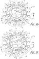
- FIGS. 3A, 3B, 3C, 3D, 3E, 3F and 3G show details of the connection of a table-top support panel to the base pedestal of the play table and walker of FIG. 1 .
- FIGS. 4A, 4B, 4C, 4D, 4E, 4F, 4G, 4H and 4I show a sequence of mounting modular table accessory panels and a coupling bracket hub onto the table-top support panel and base pedestal of the play table and walker of FIG. 1 .
- FIGS. 5A, 5B and 5C show a modular play table according to another example embodiment of the present disclosure.
- FIGS. 6A, 6B, 6C and 6D show a modular play table and associated kit of modular assembly components according to another example embodiment of the present disclosure.
- FIG. 1 shows a children's accessory or play apparatus 10 comprising a play table 20 and an orbital walker 120 .
- the walker 120 is rotationally coupled to the table 20 , to allow a child C seated in the walker to move in a generally circular orbital path (as indicated by the directional arrows) around the circumference of the table.
- U.S. Pat. No. 7,507,162 is incorporated by reference herein for background information.
- the play table 20 optionally includes a variety of play accessories coupled to and/or supported on its top surface for child interaction.
- the play table 20 includes one or more modular or interchangeable accessory panels or segments, as described in greater detail herein, allowing the table and accessory format to be changed out for a variety of interactive play experiences or applications, and/or to update the table with age and development stage appropriate features as the child grows and learns.
- the walker portion 120 is removable, allowing the table 20 to be used independently when the child no longer requires the walker for support.
- the play table portion 20 of play apparatus 10 comprises a base pedestal 30 comprising a generally planar support ring or panel 32 configured to rest on the floor or other support surface, and a plurality (four in the depicted embodiment) of table support legs or struts extending generally upwardly and inwardly at an obliquely inclined angle from lower ends coupled to the support ring to upper ends coupled to a central mounting hub 36 .
- the support panel may be otherwise configured or omitted, and/or one or more table support members may be provided.
- the mounting hub 36 includes a generally horizontal annular bearing surface or support flange 38 projecting radially outwardly and circumferentially around a generally cylindrical and upwardly extending collar or sleeve 40 , seen best in FIGS. 4D and 4E , for supporting and attaching the orbital walker portion 120 when assembled, as further described below.
- FIGS. 2A, 2B and 2C show further details and a sequence of assembly of the orbital walker portion 120 of the apparatus 10 .
- the walker 120 generally comprises a seat platform 130 , a connecting panel 140 , and one or more (two are depicted) walker support legs or struts 150 .
- the seat platform 130 defines a generally circular seat opening 132 for receiving and supporting a child seat 134 (for example a rotationally mounted roller-bearing supported ring with a fabric seat sling suspended therefrom), leg receiver couplings 136 on a bottom surface thereof, and male and/or female snap coupling flanges and/or receivers 138 A, 138 B on a distal end thereof.
- a child seat 134 for example a rotationally mounted roller-bearing supported ring with a fabric seat sling suspended therefrom
- leg receiver couplings 136 on a bottom surface thereof
- the sling of the seat 134 may be fabric that is easily removable and cleanable.
- the seat 134 may comprise a flexible or rigid material such as plastic.
- the connecting panel 140 defines a generally circular support pedestal opening 142 , with one or more (four are depicted) roller or wheel bearings 144 on a bottom surface thereof spaced circumferentially around the pedestal opening, and female and/or male snap coupling receivers and/or flanges 146 A, 146 B.
- the walker support legs 150 include an elongate strut or body portion 152 , a lower bearing hub 154 at a distal end supporting a roller or wheel 156 , and an upper connecting hub 158 for snap-coupling engagement with the leg receiver couplings 136 of the seat platform 130 .
- the walker portion 120 is assembled as shown in FIGS. 2A-2C by pressing the seat platform 130 and connecting panel 140 together to cooperatively engage the male and/or female snap coupling flanges and/or receivers 138 A, 138 B of the seat platform 130 with the female and/or male snap coupling receivers and/or flanges 146 A, 146 B of the connecting panel 140 to form a substantially rigid assembly ( FIG. 2A ).
- the seat platform 130 and connecting panel 140 may be integrally formed as a unitary component and not require assembly.
- the upper connecting hubs 158 of the walker support legs 150 are pressed into coupling engagement with the leg receiver couplings 136 of the seat platform 130 ( FIG. 2B ).
- the seat platform 130 and walker support legs 150 may be integrally formed as a unitary component and not require assembly.
- the walker and seat assembly can be disassembled for easy transport and storage.
- the legs 150 and the connecting portion 140 can be removed from the seat support 130 in order to fit into a smaller packing cube for improved and environmentally friendly packaging and economical shipping.
- the support pedestal opening 142 of the connecting panel 140 is mounted over the upwardly extending collar 40 of the mounting hub 36 of base pedestal 30 of the table 20 , with the roller bearings 144 of the connecting panel supported on the bearing surface of support flange 38 of the mounting hub of the table base pedestal ( FIG. 2C ).
- the walker portion 120 is then configured for orbital revolution or rotation about the table portion 20 , with the wheels 156 rolling on the floor or other support surface at an outer end of the walker portion, and the roller bearings 144 rolling on the bearing surface of support flange 38 at an inner end of the walker portion, as the child supported therebetween in the seat 134 walks the walker around the stationary play table. As seen in FIGS.
- the wheels 156 on the walker support legs 150 may be angularly offset to generally match the radius of curvature of their circumferential path of motion, with rotational axes of the wheels extending substantially radially along a directional line that would intersect a vertical centerline or axis of rotation of the walker around the table, for a smoother rolling movement as the walker 120 revolves around the table 20 .
- the walker portion 120 may alternatively be removed for use of the table portion 20 independently.
- the upwardly extending collar 40 of the mounting hub 36 of base pedestal 30 includes one or more, and preferably a plurality of inwardly or downwardly recessed receivers 42 having obliquely and downwardly inclined or ramped sliding contact surfaces for gravity-assisted attachment of the tabletop, as described in greater detail below.
- four downwardly inclined recesses 42 are spaced substantially equally apart around the circumference of the upper surface of the collar 40 of the mounting hub 36 , with the slopes of their downwardly inclined or ramped sliding contact surfaces all aligned or directed in the same rotational direction.
- the recesses 42 when viewed from above, define a semi-circular or arcuately curved path corresponding to path of rotational motion about a vertical axis extending through the center of the mounting hub.
- the upper surface of the collar 40 also includes one or more upwardly projecting and resiliently flexing locking tabs or latches 44 , having obliquely and upwardly inclined or ramped contact surfaces for retaining the tabletop, as described below.
- two upwardly inclined locking tabs 44 are positioned diametrically opposite one another and spaced circumferentially between adjacent downwardly inclined recesses. The slopes of the upwardly inclined ramped surfaces of the locking tabs 44 are aligned or directed in the same rotational direction as the downwardly inclined ramped surfaces of the recesses 42 .
- the table 20 further comprises a table-top support panel 50 , configured for removable attachment to the upwardly extending collar 40 of the mounting hub 36 of base pedestal 30 , and for interchangeable attachment of one or more interchangeable table leaves or modular table accessory panels thereto.
- the support panel 50 comprises a generally circular or disc shaped panel having a top surface, a bottom surface, a circumferential peripheral edge, and a central connection hub 54 for engagement with the upwardly extending collar 40 of the table's base pedestal 30 .
- the table-top support panel may be rectangular, square, triangular, polygonal, or otherwise configured.
- connection hub 54 optionally includes a lower annular flange 56 projecting transversely downward from the bottom surface of the support panel 50 that fits within the circular opening 142 of the connecting panel 140 and/or around the collar 40 of the table pedestal 30 when assembled.
- the connection hub 54 also includes an upper annular collar or flange 58 projecting transversely upward from the top surface of the support panel for engagement with the modular table accessory panels as described below.
- One or more semi-circular or otherwise shaped sockets 60 are spaced circumferentially about the upper annular collar 58 for engagement with cooperating engagement elements of the modular table accessory panels.
- One or more lower engagement recesses 62 are formed in the bottom surface of the support panel 50 along the peripheral edge, and one or more upper engagement slots 64 are formed in the top surface of the support panel along the peripheral edge, for coupling with cooperating elements of the modular table accessory panels.
- the central connection hub 54 of the table-top support panel 50 further comprises at least one, and preferably a plurality of rotational guidance members or fingers 66 projecting downwardly from the bottom surface of the table-top support panel 50 .
- rotational guidance members or fingers 66 projecting downwardly from the bottom surface of the table-top support panel 50 .
- four downwardly projecting guidance fingers 66 are spaced substantially equally apart around the circumference of the bottom surface of the central connection hub 54 .
- the guidance fingers 66 optionally comprise an obliquely inclined or ramped upper or top contact surface, and a generally parallel obliquely inclined or ramped lower or bottom contact surface configured to generally align with and slide smoothly along the confronting inclined contact surfaces of the downwardly recessed receivers 42 in the top of the collar 40 of the mounting hub 36 of base pedestal 30 , for rotational gravity-assisted attachment of the table-top support panel 50 to the base pedestal.
- FIGS. 3B-3G show a sequence of assembly for installation and attachment of the table-top support panel 50 onto the table's base pedestal 30 .
- the table-top support panel 50 is placed over pedestal 30 with the bottom surface of the support panel facing the top of the upwardly extending collar 40 of the mounting hub 36 , with the lower annular flange 56 of the connection hub 54 extending over and around the mounting hub ( FIGS. 3B and 3D ). If the walker portion 120 is installed, the connecting portion 140 is positioned captive between the annular bearing flange 38 of the pedestal 30 and the central connection hub 54 of the table-top support panel 50 .
- the table-top support panel 50 is manually rotated in a first rotational direction (for example, counter-clockwise when viewed from above) about its center axis until the guidance fingers 66 of the support panel align and drop partially into the downwardly recessed receivers 42 in the top of the collar 40 of the mounting hub 36 of base pedestal 30 ( FIG. 3E ). Because the mounting hub 36 of the pedestal 30 is positioned within the lower annular flange 56 of the table-top support panel 50 , the support panel remains in place on the pedestal as the user rotates the support panel into position. The inclined bottom contact surfaces of the guidance fingers 66 slide smoothly downward along the confronting inclined upward facing contact surfaces of the recessed receivers 42 as the support panel 50 continues to rotate and lowers under the influence of gravity onto the pedestal 30 .
- a first rotational direction for example, counter-clockwise when viewed from above
- the weight of the table-top support panel 50 provides a gravity assist to its installation and coupling onto the pedestal 30 .
- the opposed angles of inclination of the inclined contact surfaces of the guidance fingers 66 and the confronting inclined contact surfaces of the recessed receivers 42 are between about 20°-40°, for example about 30°.
- one or more retention fins 70 on the connection hub 54 of the table-top support panel 50 come into contact with the upwardly facing inclined surface of a corresponding locking tab 44 of the mounting hub 36 of the pedestal 30 , moving along the inclined face of the locking tab and pressing the tab resiliently downward ( FIG. 3E ).
- Continued rotation and downward movement of the support panel 50 moves the retention fin(s) 70 past the locking tab(s) 44 into a fully engaged position wherein abutment of the square end face of the locking tab against the retention fin prevents reverse rotation of the support panel in a second rotational direction (for example, clockwise when viewed from above), and engagement of the guidance fingers 66 against the downwardly facing inclined surfaces 68 prevents upward retraction of the support panel ( FIGS.
- the table-top support panel 50 is releasably locked into engagement with the pedestal 30 of the table portion 20 .
- the user presses each locking tab 44 downwardly out of the path of the corresponding retention fin 70 and rotates the support panel in the second rotational direction to release the guidance fingers 66 from the inclined surfaces 68 ( FIG. 3G ).
- the guidance fingers retract upwardly out of the receivers 42 , and the support panel 50 can be lifted away from the pedestal 30 .
- the table 20 further comprises one or more modular table accessory panels or table leaves 80 configured for detachable and interchangeable attachment to the table-top support panel 50 .
- the table-top support panel 50 may be used independently as the table surface, without separate accessory panels, and with or without one or more accessories mounted thereon.
- the modular accessory panels may couple directly to one another to form a tabletop assembly that may be mounted to the table base without the need for a separate support panel.
- each modular table accessory panel 80 a , 80 b , 80 c and 80 d are provided, each configured to cover a one-fourth (1 ⁇ 4) sector of the generally circular table-top support panel 50 (i.e., pie- or wedge-shaped sectors defining 1 ⁇ 4 of a circle).
- Each accessory panel 80 has a top surface, a bottom surface, arcuate inner and outer peripheral edges, and first and second radial side edges.
- the arcuate inner and outer peripheral edges span 90° of the circumference of the circular assembly of the four accessory panels when assembled into place on the table-top support panel 50 as shown in FIGS. 1 and 4I .
- One or more interactive toys or accessories are optionally provided on the top surfaces of the accessory panels 80 , for example in the form of a musical keyboard, mirror, bead-chaser, rattle, lighted accessory, character, rattle, spinner, noisemaker, puzzle, magnifier, keyboard, touch-pad, electronic display, or other features or accessories permanently affixed or detachably coupled to the panel.
- the panels 80 may have a flat surface for working, eating or other use, without accessories thereon.
- Each of the modular table accessory panels 80 optionally includes one or more detachable coupling elements for detachably and interchangeably mounting the accessory panel to the support panel 50 .
- a semi-circular or otherwise shaped peg or lug 82 projects radially inwardly from the arcuate inner peripheral edge of each panel 80 , for cooperative detachable engagement within a corresponding arched socket 60 of the support panel 50 .
- each panel 80 also includes one or more (two are shown) engagement tabs 84 directed inwardly from the outer peripheral edge along the bottom surface, for cooperative detachable engagement within a corresponding lower engagement recess 62 in the bottom surface of the support panel 50 .
- each panel 80 also includes a resilient locking tab 86 , for example positioned circumferentially between two adjacent engagement tabs 84 , for cooperative detachable engagement with a corresponding upper engagement slot 64 in the top surface of the support panel 50 .
- the resilient locking tab 86 may be formed by a U-shaped cutout in the bottom surface of the panel 80 , such that its free end can flex resiliently inward upon application of force in a transverse direction and return back to its unflexed position under the internal bias of the material at its connected end.
- An abutment rib 88 extends outwardly from a medial portion of the locking tab 86 .
- the modular table accessory panels or leaves 80 are mounted to the table-top support panel 50 by inserting the lug 82 into a respective socket 60 and sliding the accessory panel radially inward with the bottom surface of the accessory panel sliding along the top surface of the support panel ( FIG. 4D ). As the accessory panel 80 moves radially inward toward its installed position, its engagement tabs 84 move into engagement with corresponding lower engagement recesses 62 , thereby preventing the accessory panel from being lifted away from the support panel 50 .
- the resilient locking tab 86 flexes inwardly as an inboard ramped surface of the abutment rib 88 passes over the peripheral rim of the upper engagement slot 64 , and upon reaching the installed position of the support panel 50 the locking tab springs back moving the abutment rib into engagement within the engagement slot.
- An outboard square face of the abutment rib 88 of the locking tab 86 abuts against the peripheral rim of the engagement slot 64 preventing the accessory panel from being retracted away from its installed position on the table-top support panel 50 .
- each of the modular table accessory panels 80 a , 80 b , 80 c and 80 d are installed and removed sequentially in like manner. While the depicted embodiment includes four accessory panels, in alternate embodiments, one, two, three, five, six or more accessory panels may be utilized, each covering a respective sector of the table-top support panel 50 in inverse proportion to the number of accessory panels.
- a central locking cap 90 may be provided for engagement within the opening formed by the arcuate inner peripheral edges of the accessory panels 80 .
- the locking cap optionally includes a toy or accessory thereon.
- An outer circumferential flange 92 of the cap 90 may engage within a cooperating groove or channel formed in the top surface of the accessory panels, and/or one or more coupling blades 94 may extend from the cap for engagement with corresponding coupling features of the table-top support panel 50 , to provide a more secure and stable assembly.
- the user removes the central locking cap 90 by releasing the coupling blades 94 or other engagement features and lifting the cap away from the table top assembly. The user then presses the free end of the locking tab 86 of each successive accessory panel 80 inwardly to release the abutment rib 88 from engagement with the engagement slot, retracts the accessory panel outwardly, and lifts the accessory panel away from the table-top support panel 50 .
- the provision of multiple interchangeable modular table accessory panels 80 allows for customization of the table 20 as the child grows and their interests and skills change.
- one or more toys including bead chasers, electronic toys, ratchet toys, crinkle toys, spinning toys, squeakers, keyboards, musical toys, mirrors, rings, etc. may be coupled to the modular tabletop, and changed as desired to provide new and entertaining play features.
- various sets of modular table accessory panels 80 may be separately provided, allowing a parent or caregiver to select the accessory set most appropriate for their child's interests.
- the modular tabletop may further comprise one or more lights or sounds for entertaining and interacting with a child.
- the modular tabletop includes one or more accessory panels or leaves that detachably couple to each other, without including a base or support panel to which they are mounted.
- the modular tabletop assembly including the table-top support panel 50 and the modular table accessory panels 80 , can be installed onto the pedestal 30 of the table 20 in its assembled state, or alternatively the support panel can be installed onto the pedestal first, and the modular accessory panels separately installed. Also, the modular tabletop assembly can be installed onto the pedestal 30 of the table 20 with or without the walker portion 120 being installed. In this manner, the table 20 can be used independently or as part of an orbital walker.
- the modular accessory panels may be omitted, and example embodiments may include a table having a unitary or standard tabletop or support surface in combination with a gravity-assisted mounting system as disclosed for attachment onto a table pedestal or base.
- FIGS. 5A, 5B and 5C show a modular play table 210 according to another example embodiment of the present disclosure.
- Table 210 is generally similar to the above-described embodiments, with differences as noted.
- the table 210 generally comprises a tabletop portion 220 supported above a base portion 230 .
- the central locking cap or hub 290 includes a raised top surface 292 and optionally includes one or more coupling blades or attachment flanges 294 extending from an opposite bottom surface.
- the raised top surface 292 may be rounded or radiused, and defines one or more slots 295 formed therein, for receiving one or more vertical divider panels 255 supported in an upright position on top of the tabletop 220 .
- the center cap 290 defines four slots 295 a , 295 b , 295 c and 295 d arranged in crosswise form spaced at about 90° from one another, into which one or more vertical panels 255 a , 255 b , 255 c and 255 d may be retained.
- the lower edges of the panels 255 are configured to fit within the slots 295 with a running or sliding fit, so that a child or adult caregiver can easily install and remove the panels by hand to reconfigure the table 210 as desired.
- the panels 255 may include one or more toys or other entertainment or interactivity features or elements attached thereto or integrally formed therewith.
- the tabletop 220 includes one or more additional slots or retainer elements, for example around the periphery of the tabletop, for providing additional support and retention of the panels 255 in place on the tabletop.
- additional slots or retainer elements for example around the periphery of the tabletop, for providing additional support and retention of the panels 255 in place on the tabletop.
- One, two ( FIG. 5A ), three, or four ( FIG. 5B ) panels 255 may be installed, depending on the desired table configuration and use.
- the center cap 290 defines one, two, three, four, five, six or more slots, to retain up to a like number of divider panels on the tabletop in similar fashion.
- FIGS. 6A, 6B, 6C and 6D show a modular play table 310 and associated kit of modular assembly components according to another example embodiment of the present disclosure.
- Table 310 is generally similar to the above-described embodiments, with differences as noted.
- the table 310 generally comprises a tabletop portion 320 supported above a base portion 330 .
- the table base 330 comprises one or more generally upright support legs 334 (four legs 334 a , 334 b , 334 c , 334 d are present in the depicted embodiment).
- Each leg 334 optionally comprises a leg support 336 configured to detachably couple an upper end of the respective leg to the tabletop 320 , and a foot 338 at a lower end of the leg for contacting the floor or other support surface.
- the leg supports 336 optionally include a connector for a diagonal brace between the leg 334 and the tabletop 320 .
- the tabletop portion 320 includes a modular table-top support panel comprising first and second side table base insert panels 352 a , 352 b at opposite ends thereof, and at least one mid-table base insert panel 354 coupled between the side table base insert panels.
- the tabletop portion 320 also includes one or more modular table accessory panels, such as for example, quarter-circular (90°) table quadrants 382 (four table quadrants 382 a , 382 b , 382 c , 382 d are present in the depicted embodiment) and table side tops 384 (two table side tops 384 a and 384 b are present in the depicted embodiment).
- the modular table accessory panels may include one or more toys or accessories and are optionally configured for detachable and interchangeable connection with the table base 330 and/or the table-top support panel, in similar fashion to the above described embodiments.
- the tabletop portion 320 optionally also includes a peripheral support ring extending around its outer periphery to retain the components of the modular table-top support panel and/or the modular table accessory panels in their assembled configuration, for example comprising one or more radiused end table supports 386 and/or side table supports 388 .
- a peripheral support ring extending around its outer periphery to retain the components of the modular table-top support panel and/or the modular table accessory panels in their assembled configuration, for example comprising one or more radiused end table supports 386 and/or side table supports 388 .
- two quarter-circular (90°) radiused end table supports 386 a , 386 b are provided at a first end of the tabletop 320
- two more radiused end table supports 386 c , 386 d are provided at an opposite end of the tabletop, with two side table supports 388 a , 388 b between the end table supports at opposite sides of the tabletop.
- the end table supports 386 and side table supports 388 optionally include cooperatively interengaging detachable coupling elements at each end thereof for attachment together to form a peripheral ring to retain the tabletop in its assembled configuration.
- the leg supports 336 optionally include receivers or coupling elements for detachable engagement with the end table supports 386 and/or the side table supports 388 , or to other components of the tabletop 320 to attach the legs 334 of the base 330 to the tabletop.
- central locking table cap(s) or hub(s) 390 may be installed into or onto the tabletop 320 , optionally including one or more slots or other engagement features for detachably installing one or more upright divider panels 355 , as shown in FIG. 6D (three panels 355 a , 355 b , 355 c are present in the depicted embodiment).
- the example embodiments disclosed herein comprise various components and parts which may be assembled, disassembled, and reassembled into various configurations in modular fashion, as described and shown herein.
- the walker portion may be connected to or removed from the play table.
- the modular table accessory panels may be interchangeably installed and replaced.
- the leg components of the table may be interchangeable with the legs of the walker and/or other product configurations.
- the mid table base insert and/or table side tops may be utilized to assemble an oval or elongate table or can be removed and omitted to assemble a round or circular table.
- Various other combinations and sub-combinations of modular components may be utilized in similar fashion.
- the various components may be provided separately, or together in the form of a kit or system comprising any two or more of said components in combination.
- a kit or system of components may be provided as shown in FIG. 6C , comprising any or all of: four leg supports, four feet, four table supports, four table quadrants, four leg parts, two table caps, two table side tops, two side table supports, two side table base inserts, and/or one mid-table base insert components.
- additional component types may be included, and/or one or more component types may be omitted.
- instructions for assembling one, two or more modular products or assemblies can be provided, for example in the form of a booklet or written and/or graphical instructions, online video instructions, a mobile phone app, or other instructional means are optionally provided.
- one or more tools may optionally be included for assembling the components.
- a table according to the present disclosure can be configured for adult or other use, for example as a work table, dining table, conference table, desk, medical examination table, retail display platform, and/or other configurations for different applications.
- one or more of the modular accessory panels may be flat rather than having toys or accessories mounted thereon.
- the accessory panels may include other features such as electronic keyboards, touchpads, video display panels, electronic menu and ordering systems, audio speakers, microphones, etc., allowing user customization for various purposes or applications.
- the table-top support panel or table base may include electric power, electronic data, fluid delivery, mechanical, magnetic, and/or other connection elements or ports positioned to align and connect with cooperating connection elements on the modular table accessory panels when assembled.
Landscapes
- Health & Medical Sciences (AREA)
- General Health & Medical Sciences (AREA)
- Pediatric Medicine (AREA)
- Tables And Desks Characterized By Structural Shape (AREA)
Abstract
Description
Claims (34)
Priority Applications (1)
| Application Number | Priority Date | Filing Date | Title |
|---|---|---|---|
| US16/571,647 US10959539B2 (en) | 2018-09-18 | 2019-09-16 | Modular table and walker |
Applications Claiming Priority (2)
| Application Number | Priority Date | Filing Date | Title |
|---|---|---|---|
| US201862732978P | 2018-09-18 | 2018-09-18 | |
| US16/571,647 US10959539B2 (en) | 2018-09-18 | 2019-09-16 | Modular table and walker |
Publications (2)
| Publication Number | Publication Date |
|---|---|
| US20200085207A1 US20200085207A1 (en) | 2020-03-19 |
| US10959539B2 true US10959539B2 (en) | 2021-03-30 |
Family
ID=69772613
Family Applications (1)
| Application Number | Title | Priority Date | Filing Date |
|---|---|---|---|
| US16/571,647 Active US10959539B2 (en) | 2018-09-18 | 2019-09-16 | Modular table and walker |
Country Status (2)
| Country | Link |
|---|---|
| US (1) | US10959539B2 (en) |
| CN (1) | CN211961538U (en) |
Cited By (2)
| Publication number | Priority date | Publication date | Assignee | Title |
|---|---|---|---|---|
| USD945533S1 (en) * | 2020-06-11 | 2022-03-08 | Kids2, Inc. | Bounce entertainer for children |
| USD961003S1 (en) * | 2021-02-25 | 2022-08-16 | Yufen Cai | Game table |
Families Citing this family (2)
| Publication number | Priority date | Publication date | Assignee | Title |
|---|---|---|---|---|
| US20230228288A1 (en) * | 2022-01-19 | 2023-07-20 | Jin Sun Gee Plastics Co., Ltd. | Tray assembly |
| USD1025233S1 (en) * | 2024-01-09 | 2024-04-30 | Xiaobo Chen | Toy table |
Citations (83)
| Publication number | Priority date | Publication date | Assignee | Title |
|---|---|---|---|---|
| US68637A (en) | 1867-09-10 | mason | ||
| US71220A (en) | 1867-11-19 | Improved baby-walker | ||
| US82304A (en) | 1868-09-22 | geisleb | ||
| US124706A (en) | 1872-03-19 | Improvement in baby-walking apparatus | ||
| US341167A (en) | 1886-05-04 | Baby-walker | ||
| US368477A (en) | 1887-08-16 | Baby-walker | ||
| US451128A (en) | 1891-04-28 | Baby-walker | ||
| US671058A (en) | 1900-11-23 | 1901-04-02 | John Resetar | Baby-walker. |
| US822329A (en) | 1905-05-01 | 1906-06-05 | Margaret A Wilcox | Physical-culture appliance. |
| US903731A (en) | 1908-04-20 | 1908-11-10 | Ferdinand Kull | Training device. |
| US1297018A (en) | 1918-04-04 | 1919-03-11 | Nora E Jewett | Perambulator and cradle. |
| US1297800A (en) | 1918-02-23 | 1919-03-18 | Henry L Cranford | Baby-walker. |
| US1437179A (en) | 1921-12-30 | 1922-11-28 | Ovide Auger | Walking chair for children |
| US1469436A (en) | 1921-01-24 | 1923-10-02 | Milton G Fornia | Baby walker or exerciser |
| US2308626A (en) | 1939-05-22 | 1943-01-19 | William H Reinholz | Baby walker |
| US2352450A (en) | 1940-06-12 | 1944-06-27 | William H Reinholz | Baby walker |
| US2499164A (en) | 1947-01-16 | 1950-02-28 | Clarence M Richardson | Baby educator |
| US3049350A (en) | 1960-06-20 | 1962-08-14 | Ora C Walker | Jumper walker |
| US3127170A (en) | 1964-03-31 | Children s play table | ||
| US3303797A (en) | 1966-01-24 | 1967-02-14 | Mueller Herman | Folding table |
| US3437390A (en) * | 1967-06-19 | 1969-04-08 | Tele Quick Corp | Apparatus and method for repairing equipment |
| US3533362A (en) * | 1968-07-24 | 1970-10-13 | Oxford Filing Supply Co Inc | Modular office table or desk |
| US3721437A (en) | 1972-03-03 | 1973-03-20 | Raymond Lee Organization Inc | Walking trainer |
| US3730587A (en) | 1970-05-22 | 1973-05-01 | S Bloxham | Exercising apparatus for small children |
| US3741852A (en) * | 1971-06-03 | 1973-06-26 | American Seating Co | Segmental multiunit study table |
| US3985082A (en) | 1975-04-02 | 1976-10-12 | Barac Dragoje R | Electric walker |
| USD280368S (en) * | 1982-09-15 | 1985-09-03 | Gabriella Crespi | Adjustable table |
| US4621804A (en) | 1985-03-25 | 1986-11-11 | R-Jayco Ltd. | Therapeutic roller/walker |
| US4743008A (en) | 1986-12-19 | 1988-05-10 | Fermaglich Daniel R | Infant exerciser |
| US4795151A (en) | 1987-09-30 | 1989-01-03 | Mulcaster Donald L | Baby walker with safety track feature |
| US4907571A (en) | 1987-08-21 | 1990-03-13 | Infutec Inc. | Apparatus for the practice of ambulation |
| US4922835A (en) * | 1989-02-17 | 1990-05-08 | Trychest Pty., Limited | Multi-part table |
| US5016405A (en) * | 1989-04-18 | 1991-05-21 | Rosemount Office Systems, Inc. | Modular workstations |
| USD320528S (en) | 1989-11-20 | 1991-10-08 | Safety 1St, Inc. | Swivel bath seat for infants |
| US5085428A (en) | 1990-05-24 | 1992-02-04 | Fermaglich Daniel R | Baby walker |
| US5197394A (en) | 1989-12-09 | 1993-03-30 | Schmidt Brigitta C | Garden umbrella |
| US5211607A (en) | 1990-05-24 | 1993-05-18 | Fermaglish Daniel R | Baby activity center |
| US5237937A (en) | 1992-03-26 | 1993-08-24 | Jacques Peltier | Expansible table |
| US5302163A (en) | 1990-05-24 | 1994-04-12 | Daniel R. Fermaglich | Infant exerciser and activity center |
| US5366231A (en) | 1993-05-12 | 1994-11-22 | Hung Chin Pin | Movable base for a baby walker |
| US5409246A (en) | 1993-07-14 | 1995-04-25 | Ali; Abdulkadir H. | Tethered baby walker |
| US5433682A (en) | 1994-06-01 | 1995-07-18 | Pediasafe Products, Inc. | Infant exerciser and activity center |
| US5438937A (en) * | 1993-06-08 | 1995-08-08 | Steelcase Inc. | Mobile table system |
| US5577801A (en) | 1992-03-27 | 1996-11-26 | Gloeckl Josef | Active dynamic seat |
| US5590892A (en) | 1995-03-01 | 1997-01-07 | Hu; Stephen | Baby's carriage for teaching children to walk |
| US5622118A (en) * | 1993-07-16 | 1997-04-22 | Rowan; Thomas J. | Convertible support apparatus |
| US5673631A (en) * | 1996-05-13 | 1997-10-07 | Guns; Louis L. | Table joining leaf |
| US5688211A (en) | 1995-11-13 | 1997-11-18 | Kolcraft Enterprises, Inc. | Collapsible child exerciser device |
| US5735220A (en) * | 1996-12-16 | 1998-04-07 | Wang; Ming-Cheng | Slide rails of extensible table |
| US5967058A (en) * | 1997-06-02 | 1999-10-19 | Flex-Rest, Llc | Articulatable furniture |
| US6001047A (en) | 1998-03-05 | 1999-12-14 | Ferrara; Giovanna | Safe baby walker |
| US6000750A (en) | 1996-10-25 | 1999-12-14 | The First Years Inc. | Convertible play center for children |
| US6048290A (en) | 1998-09-30 | 2000-04-11 | Link Treasure Limited | Baby walker |
| US6182581B1 (en) * | 1999-09-30 | 2001-02-06 | Boyce Products, Ltd. | Modular table |
| US6299247B1 (en) | 1993-10-01 | 2001-10-09 | Evenflo Company, Inc. | Child exerciser/rocker |
| US6363866B1 (en) * | 2000-01-20 | 2002-04-02 | Hou Technology Inc. | Table construction |
| US20020164917A1 (en) * | 2001-05-01 | 2002-11-07 | Charles Keegan | Convertible activity center |
| US6477966B1 (en) | 2000-04-04 | 2002-11-12 | Thomas M. Petryna | Modular rotatable tray system |
| USD465440S1 (en) | 2001-10-19 | 2002-11-12 | Evenflo Company, Inc. | Orbital infant exerciser |
| US6616629B1 (en) | 1994-06-24 | 2003-09-09 | Schneider (Europe) A.G. | Medical appliance with centering balloon |
| US6837386B1 (en) | 2002-12-18 | 2005-01-04 | Aardwolf Integrated Storage Systems, Llc | Space saving support shelf for column mounting |
| US20050247241A1 (en) * | 2004-05-04 | 2005-11-10 | Sherman Brad J | Modular table system |
| US7025364B1 (en) | 2003-12-23 | 2006-04-11 | William A Clarke | Combined stroller, walker and play station |
| US20060117669A1 (en) * | 2004-12-06 | 2006-06-08 | Baloga Mark A | Multi-use conferencing space, table arrangement and display configuration |
| US20060180055A1 (en) * | 2005-02-15 | 2006-08-17 | Dodaz, Inc. | Composite assembly of interconnectable furniture |
| US7097599B2 (en) | 2002-08-20 | 2006-08-29 | Gates Donald K | Infant walker |
| US7168199B2 (en) | 2002-04-30 | 2007-01-30 | Krien Gary L | Portable seat and platform support |
| US7247100B2 (en) | 2004-01-16 | 2007-07-24 | Kids Ii, Inc. | Orbital walker with activity table |
| US20070265144A1 (en) * | 2004-01-16 | 2007-11-15 | Kids Ii, Inc. | Orbital walker with activity table |
| USD618474S1 (en) * | 2008-07-07 | 2010-06-29 | Jangir Maddadi AB | Extendable table |
| US20120287226A1 (en) * | 2004-12-06 | 2012-11-15 | Baloga Mark A | Multi-Use Conferencing Space, Table Arrangement and Display Configuration |
| US8397651B2 (en) * | 2007-10-10 | 2013-03-19 | Davida Levy | Configurable table and methods of use |
| US8475342B2 (en) | 2009-07-03 | 2013-07-02 | Daniel William Flowers | Infant crawler-walker motor development apparatus |
| CN104055319A (en) | 2013-03-22 | 2014-09-24 | 朱俐敏 | Table with replaceable tabletops |
| US20150035321A1 (en) * | 2013-08-05 | 2015-02-05 | Chiu-San Lee | Safety frame for baby walking |
| US8950805B2 (en) | 2003-01-20 | 2015-02-10 | Charles Keen | Seating apparatus |
| US8997661B1 (en) | 2014-06-10 | 2015-04-07 | Grk Manufacturing Company | Table top extension and method for increasing the table top surface area of an existing table top |
| USD745798S1 (en) * | 2013-07-11 | 2015-12-22 | Tables Modulaires Positionnelles 2008 Inc. | Table top |
| USD770207S1 (en) * | 2014-08-18 | 2016-11-01 | Tables Modulaires Positionnelles 2008 Inc. | Table top |
| USD774338S1 (en) * | 2014-08-18 | 2016-12-20 | Tables Modulaires Positionnelles 2008 Inc. | Table top |
| USD786595S1 (en) * | 2014-09-16 | 2017-05-16 | Jane Mary Mingenbach | Furniture top |
| US20180317668A1 (en) * | 2017-05-02 | 2018-11-08 | Blue Box Toy Factory Limited | Multi-functional entertainer for a child |
| US20190125070A1 (en) * | 2011-04-04 | 2019-05-02 | Regency Seating, Inc. | Modular conference table |
-
2019
- 2019-09-16 US US16/571,647 patent/US10959539B2/en active Active
- 2019-09-18 CN CN201921556712.6U patent/CN211961538U/en active Active
Patent Citations (91)
| Publication number | Priority date | Publication date | Assignee | Title |
|---|---|---|---|---|
| US3127170A (en) | 1964-03-31 | Children s play table | ||
| US71220A (en) | 1867-11-19 | Improved baby-walker | ||
| US82304A (en) | 1868-09-22 | geisleb | ||
| US124706A (en) | 1872-03-19 | Improvement in baby-walking apparatus | ||
| US341167A (en) | 1886-05-04 | Baby-walker | ||
| US368477A (en) | 1887-08-16 | Baby-walker | ||
| US451128A (en) | 1891-04-28 | Baby-walker | ||
| US68637A (en) | 1867-09-10 | mason | ||
| US671058A (en) | 1900-11-23 | 1901-04-02 | John Resetar | Baby-walker. |
| US822329A (en) | 1905-05-01 | 1906-06-05 | Margaret A Wilcox | Physical-culture appliance. |
| US903731A (en) | 1908-04-20 | 1908-11-10 | Ferdinand Kull | Training device. |
| US1297800A (en) | 1918-02-23 | 1919-03-18 | Henry L Cranford | Baby-walker. |
| US1297018A (en) | 1918-04-04 | 1919-03-11 | Nora E Jewett | Perambulator and cradle. |
| US1469436A (en) | 1921-01-24 | 1923-10-02 | Milton G Fornia | Baby walker or exerciser |
| US1437179A (en) | 1921-12-30 | 1922-11-28 | Ovide Auger | Walking chair for children |
| US2308626A (en) | 1939-05-22 | 1943-01-19 | William H Reinholz | Baby walker |
| US2352450A (en) | 1940-06-12 | 1944-06-27 | William H Reinholz | Baby walker |
| US2499164A (en) | 1947-01-16 | 1950-02-28 | Clarence M Richardson | Baby educator |
| US3049350A (en) | 1960-06-20 | 1962-08-14 | Ora C Walker | Jumper walker |
| US3303797A (en) | 1966-01-24 | 1967-02-14 | Mueller Herman | Folding table |
| US3437390A (en) * | 1967-06-19 | 1969-04-08 | Tele Quick Corp | Apparatus and method for repairing equipment |
| US3533362A (en) * | 1968-07-24 | 1970-10-13 | Oxford Filing Supply Co Inc | Modular office table or desk |
| US3730587A (en) | 1970-05-22 | 1973-05-01 | S Bloxham | Exercising apparatus for small children |
| US3741852A (en) * | 1971-06-03 | 1973-06-26 | American Seating Co | Segmental multiunit study table |
| US3721437A (en) | 1972-03-03 | 1973-03-20 | Raymond Lee Organization Inc | Walking trainer |
| US3985082A (en) | 1975-04-02 | 1976-10-12 | Barac Dragoje R | Electric walker |
| USD280368S (en) * | 1982-09-15 | 1985-09-03 | Gabriella Crespi | Adjustable table |
| US4621804A (en) | 1985-03-25 | 1986-11-11 | R-Jayco Ltd. | Therapeutic roller/walker |
| US4743008A (en) | 1986-12-19 | 1988-05-10 | Fermaglich Daniel R | Infant exerciser |
| US4907571A (en) | 1987-08-21 | 1990-03-13 | Infutec Inc. | Apparatus for the practice of ambulation |
| US5050504A (en) | 1987-09-30 | 1991-09-24 | Mulcaster Donald L | Baby walker with safety track feature |
| US4795151A (en) | 1987-09-30 | 1989-01-03 | Mulcaster Donald L | Baby walker with safety track feature |
| US4922835A (en) * | 1989-02-17 | 1990-05-08 | Trychest Pty., Limited | Multi-part table |
| US5016405A (en) * | 1989-04-18 | 1991-05-21 | Rosemount Office Systems, Inc. | Modular workstations |
| USD320528S (en) | 1989-11-20 | 1991-10-08 | Safety 1St, Inc. | Swivel bath seat for infants |
| US5197394A (en) | 1989-12-09 | 1993-03-30 | Schmidt Brigitta C | Garden umbrella |
| US5085428A (en) | 1990-05-24 | 1992-02-04 | Fermaglich Daniel R | Baby walker |
| US5211607A (en) | 1990-05-24 | 1993-05-18 | Fermaglish Daniel R | Baby activity center |
| US5302163A (en) | 1990-05-24 | 1994-04-12 | Daniel R. Fermaglich | Infant exerciser and activity center |
| US5237937A (en) | 1992-03-26 | 1993-08-24 | Jacques Peltier | Expansible table |
| US5577801A (en) | 1992-03-27 | 1996-11-26 | Gloeckl Josef | Active dynamic seat |
| US5366231A (en) | 1993-05-12 | 1994-11-22 | Hung Chin Pin | Movable base for a baby walker |
| US5438937A (en) * | 1993-06-08 | 1995-08-08 | Steelcase Inc. | Mobile table system |
| US5409246A (en) | 1993-07-14 | 1995-04-25 | Ali; Abdulkadir H. | Tethered baby walker |
| US5622118A (en) * | 1993-07-16 | 1997-04-22 | Rowan; Thomas J. | Convertible support apparatus |
| US6299247B1 (en) | 1993-10-01 | 2001-10-09 | Evenflo Company, Inc. | Child exerciser/rocker |
| US5433682A (en) | 1994-06-01 | 1995-07-18 | Pediasafe Products, Inc. | Infant exerciser and activity center |
| US6616629B1 (en) | 1994-06-24 | 2003-09-09 | Schneider (Europe) A.G. | Medical appliance with centering balloon |
| US5590892A (en) | 1995-03-01 | 1997-01-07 | Hu; Stephen | Baby's carriage for teaching children to walk |
| US5688211A (en) | 1995-11-13 | 1997-11-18 | Kolcraft Enterprises, Inc. | Collapsible child exerciser device |
| US5673631A (en) * | 1996-05-13 | 1997-10-07 | Guns; Louis L. | Table joining leaf |
| US6000750A (en) | 1996-10-25 | 1999-12-14 | The First Years Inc. | Convertible play center for children |
| US5735220A (en) * | 1996-12-16 | 1998-04-07 | Wang; Ming-Cheng | Slide rails of extensible table |
| US5967058A (en) * | 1997-06-02 | 1999-10-19 | Flex-Rest, Llc | Articulatable furniture |
| US6001047A (en) | 1998-03-05 | 1999-12-14 | Ferrara; Giovanna | Safe baby walker |
| US6048290A (en) | 1998-09-30 | 2000-04-11 | Link Treasure Limited | Baby walker |
| US6182581B1 (en) * | 1999-09-30 | 2001-02-06 | Boyce Products, Ltd. | Modular table |
| US6363866B1 (en) * | 2000-01-20 | 2002-04-02 | Hou Technology Inc. | Table construction |
| US6477966B1 (en) | 2000-04-04 | 2002-11-12 | Thomas M. Petryna | Modular rotatable tray system |
| US20020164917A1 (en) * | 2001-05-01 | 2002-11-07 | Charles Keegan | Convertible activity center |
| USD465440S1 (en) | 2001-10-19 | 2002-11-12 | Evenflo Company, Inc. | Orbital infant exerciser |
| US7168199B2 (en) | 2002-04-30 | 2007-01-30 | Krien Gary L | Portable seat and platform support |
| US20070124981A1 (en) | 2002-04-30 | 2007-06-07 | Krien David A | Portable seat and platform support |
| US7326152B2 (en) | 2002-08-20 | 2008-02-05 | Gates Donald K | Infant walker |
| US7097599B2 (en) | 2002-08-20 | 2006-08-29 | Gates Donald K | Infant walker |
| US6837386B1 (en) | 2002-12-18 | 2005-01-04 | Aardwolf Integrated Storage Systems, Llc | Space saving support shelf for column mounting |
| US8950805B2 (en) | 2003-01-20 | 2015-02-10 | Charles Keen | Seating apparatus |
| US20150265049A1 (en) | 2003-01-20 | 2015-09-24 | Charles Keen | Seating apparatus |
| US7025364B1 (en) | 2003-12-23 | 2006-04-11 | William A Clarke | Combined stroller, walker and play station |
| US20070200397A1 (en) | 2004-01-16 | 2007-08-30 | Kids Ii, Inc. | Orbital walker with activity table |
| US7247100B2 (en) | 2004-01-16 | 2007-07-24 | Kids Ii, Inc. | Orbital walker with activity table |
| US20070265144A1 (en) * | 2004-01-16 | 2007-11-15 | Kids Ii, Inc. | Orbital walker with activity table |
| US7507162B2 (en) * | 2004-01-16 | 2009-03-24 | Kids Ii, Inc. | Orbital walker with activity table |
| US20050247241A1 (en) * | 2004-05-04 | 2005-11-10 | Sherman Brad J | Modular table system |
| US10492608B2 (en) * | 2004-12-06 | 2019-12-03 | Steelcase Inc. | Multi-use conferencing space, table arrangement and display configuration |
| US20120287226A1 (en) * | 2004-12-06 | 2012-11-15 | Baloga Mark A | Multi-Use Conferencing Space, Table Arrangement and Display Configuration |
| US20060117669A1 (en) * | 2004-12-06 | 2006-06-08 | Baloga Mark A | Multi-use conferencing space, table arrangement and display configuration |
| US20060180055A1 (en) * | 2005-02-15 | 2006-08-17 | Dodaz, Inc. | Composite assembly of interconnectable furniture |
| US8397651B2 (en) * | 2007-10-10 | 2013-03-19 | Davida Levy | Configurable table and methods of use |
| USD618474S1 (en) * | 2008-07-07 | 2010-06-29 | Jangir Maddadi AB | Extendable table |
| US8475342B2 (en) | 2009-07-03 | 2013-07-02 | Daniel William Flowers | Infant crawler-walker motor development apparatus |
| US20190125070A1 (en) * | 2011-04-04 | 2019-05-02 | Regency Seating, Inc. | Modular conference table |
| CN104055319A (en) | 2013-03-22 | 2014-09-24 | 朱俐敏 | Table with replaceable tabletops |
| USD745798S1 (en) * | 2013-07-11 | 2015-12-22 | Tables Modulaires Positionnelles 2008 Inc. | Table top |
| US20150035321A1 (en) * | 2013-08-05 | 2015-02-05 | Chiu-San Lee | Safety frame for baby walking |
| US8997661B1 (en) | 2014-06-10 | 2015-04-07 | Grk Manufacturing Company | Table top extension and method for increasing the table top surface area of an existing table top |
| USD770207S1 (en) * | 2014-08-18 | 2016-11-01 | Tables Modulaires Positionnelles 2008 Inc. | Table top |
| USD774338S1 (en) * | 2014-08-18 | 2016-12-20 | Tables Modulaires Positionnelles 2008 Inc. | Table top |
| USD839648S1 (en) * | 2014-08-18 | 2019-02-05 | Tables Modulaires Positionnelles 2008 Inc. | Table top |
| USD786595S1 (en) * | 2014-09-16 | 2017-05-16 | Jane Mary Mingenbach | Furniture top |
| US20180317668A1 (en) * | 2017-05-02 | 2018-11-08 | Blue Box Toy Factory Limited | Multi-functional entertainer for a child |
Non-Patent Citations (1)
| Title |
|---|
| Chinese First Office for App. No. 201921556712.6; dated May 25, 2020; 2 pgs. |
Cited By (2)
| Publication number | Priority date | Publication date | Assignee | Title |
|---|---|---|---|---|
| USD945533S1 (en) * | 2020-06-11 | 2022-03-08 | Kids2, Inc. | Bounce entertainer for children |
| USD961003S1 (en) * | 2021-02-25 | 2022-08-16 | Yufen Cai | Game table |
Also Published As
| Publication number | Publication date |
|---|---|
| US20200085207A1 (en) | 2020-03-19 |
| CN211961538U (en) | 2020-11-20 |
Similar Documents
| Publication | Publication Date | Title |
|---|---|---|
| US10959539B2 (en) | Modular table and walker | |
| US6682139B2 (en) | Child activity center, entertainment system, and components thereof | |
| US7507162B2 (en) | Orbital walker with activity table | |
| US7247100B2 (en) | Orbital walker with activity table | |
| US10735572B2 (en) | Spinning accessory for a mobile electronic device | |
| US8544390B1 (en) | Lazy susan device with snap fit top and base | |
| US10456701B2 (en) | Infant activity center | |
| US9107493B2 (en) | Pop-up rotatable tray and a tabletop comprising the same | |
| CN108786124B (en) | Multifunctional entertainment device for children | |
| US5451093A (en) | Spring-mounted infant seat | |
| US6000750A (en) | Convertible play center for children | |
| AU2020256370A1 (en) | Spinning accessory for a mobile electronic device | |
| US20180035824A1 (en) | Portable activity center | |
| US20080182477A1 (en) | Child's play gym, also usable as a seat | |
| US20060237944A1 (en) | Stationary child exercise apparatus | |
| US20110104979A1 (en) | Child activity systems | |
| US20080113581A1 (en) | Convertible infant activity center | |
| US5067923A (en) | Training system for spinning objects by hand | |
| US7153181B2 (en) | Toy support structure | |
| US20090200841A1 (en) | Dual infant activity center | |
| US20230085412A1 (en) | Play tent apparatus | |
| JP3044863U (en) | Rotating saucer for flowerpot | |
| JP3005288U (en) | Rotating support | |
| AU660335B2 (en) | Children's play structure with interchangeable scenes | |
| CA2172174A1 (en) | In-place walker |
Legal Events
| Date | Code | Title | Description |
|---|---|---|---|
| FEPP | Fee payment procedure |
Free format text: ENTITY STATUS SET TO UNDISCOUNTED (ORIGINAL EVENT CODE: BIG.); ENTITY STATUS OF PATENT OWNER: LARGE ENTITY |
|
| FEPP | Fee payment procedure |
Free format text: ENTITY STATUS SET TO SMALL (ORIGINAL EVENT CODE: SMAL); ENTITY STATUS OF PATENT OWNER: LARGE ENTITY |
|
| STPP | Information on status: patent application and granting procedure in general |
Free format text: DOCKETED NEW CASE - READY FOR EXAMINATION |
|
| STPP | Information on status: patent application and granting procedure in general |
Free format text: RESPONSE TO NON-FINAL OFFICE ACTION ENTERED AND FORWARDED TO EXAMINER |
|
| AS | Assignment |
Owner name: KIDS2, INC., GEORGIA Free format text: ASSIGNMENT OF ASSIGNORS INTEREST;ASSIGNORS:RENNO, SHADI;POMEROY, BLAKE;SIGNING DATES FROM 20121107 TO 20150309;REEL/FRAME:055257/0674 |
|
| FEPP | Fee payment procedure |
Free format text: ENTITY STATUS SET TO UNDISCOUNTED (ORIGINAL EVENT CODE: BIG.); ENTITY STATUS OF PATENT OWNER: LARGE ENTITY |
|
| STPP | Information on status: patent application and granting procedure in general |
Free format text: PUBLICATIONS -- ISSUE FEE PAYMENT VERIFIED |
|
| STCF | Information on status: patent grant |
Free format text: PATENTED CASE |
|
| AS | Assignment |
Owner name: WELLS FARGO BANK, NATIONAL ASSOCIATION, AS AGENT, GEORGIA Free format text: SECURITY AGREEMENT;ASSIGNORS:KIDS2, INC.;GOT I, LLC;GOT II, LLC;AND OTHERS;REEL/FRAME:060413/0821 Effective date: 20220622 |
|
| AS | Assignment |
Owner name: KIDS2, LLC, GEORGIA Free format text: BUSINESS CONVERSION;ASSIGNOR:KIDS2, INC.;REEL/FRAME:066943/0422 Effective date: 20231229 |