US10935386B2 - Self-propelled device, and method and travel control computer program of controlling traveling of self-propelled device - Google Patents

Self-propelled device, and method and travel control computer program of controlling traveling of self-propelled device Download PDF

Info

Publication number
US10935386B2
US10935386B2 US16/610,319 US201816610319A US10935386B2 US 10935386 B2 US10935386 B2 US 10935386B2 US 201816610319 A US201816610319 A US 201816610319A US 10935386 B2 US10935386 B2 US 10935386B2
Authority
US
United States
Prior art keywords
point
self
offset
propelled device
virtual path
Prior art date
Legal status (The legal status is an assumption and is not a legal conclusion. Google has not performed a legal analysis and makes no representation as to the accuracy of the status listed.)
Active
Application number
US16/610,319
Other versions
US20200080850A1 (en
Inventor
Mayuko Mori
Masaaki TANOUE
Kazuteru TOBITA
Satoshi Ozaki
Current Assignee (The listed assignees may be inaccurate. Google has not performed a legal analysis and makes no representation or warranty as to the accuracy of the list.)
NSK Ltd
Original Assignee
NSK Ltd
Priority date (The priority date is an assumption and is not a legal conclusion. Google has not performed a legal analysis and makes no representation as to the accuracy of the date listed.)
Filing date
Publication date
Application filed by NSK Ltd filed Critical NSK Ltd
Assigned to NSK LTD. reassignment NSK LTD. ASSIGNMENT OF ASSIGNORS INTEREST (SEE DOCUMENT FOR DETAILS). Assignors: OZAKI, SATOSHI, TOBITA, Kazuteru, TANOUE, Masaaki, MORI, MAYUKO
Publication of US20200080850A1 publication Critical patent/US20200080850A1/en
Application granted granted Critical
Publication of US10935386B2 publication Critical patent/US10935386B2/en
Active legal-status Critical Current
Anticipated expiration legal-status Critical

Links

Images

Classifications

    • GPHYSICS
    • G01MEASURING; TESTING
    • G01CMEASURING DISTANCES, LEVELS OR BEARINGS; SURVEYING; NAVIGATION; GYROSCOPIC INSTRUMENTS; PHOTOGRAMMETRY OR VIDEOGRAMMETRY
    • G01C21/00Navigation; Navigational instruments not provided for in groups G01C1/00 - G01C19/00
    • G01C21/20Instruments for performing navigational calculations
    • GPHYSICS
    • G01MEASURING; TESTING
    • G01CMEASURING DISTANCES, LEVELS OR BEARINGS; SURVEYING; NAVIGATION; GYROSCOPIC INSTRUMENTS; PHOTOGRAMMETRY OR VIDEOGRAMMETRY
    • G01C21/00Navigation; Navigational instruments not provided for in groups G01C1/00 - G01C19/00
    • G01C21/26Navigation; Navigational instruments not provided for in groups G01C1/00 - G01C19/00 specially adapted for navigation in a road network
    • G01C21/34Route searching; Route guidance
    • GPHYSICS
    • G01MEASURING; TESTING
    • G01CMEASURING DISTANCES, LEVELS OR BEARINGS; SURVEYING; NAVIGATION; GYROSCOPIC INSTRUMENTS; PHOTOGRAMMETRY OR VIDEOGRAMMETRY
    • G01C21/00Navigation; Navigational instruments not provided for in groups G01C1/00 - G01C19/00
    • G01C21/20Instruments for performing navigational calculations
    • G01C21/206Instruments for performing navigational calculations specially adapted for indoor navigation
    • GPHYSICS
    • G05CONTROLLING; REGULATING
    • G05DSYSTEMS FOR CONTROLLING OR REGULATING NON-ELECTRIC VARIABLES
    • G05D1/00Control of position, course, altitude or attitude of land, water, air or space vehicles, e.g. using automatic pilots
    • G05D1/02Control of position or course in two dimensions
    • G05D1/021Control of position or course in two dimensions specially adapted to land vehicles
    • G05D1/0212Control of position or course in two dimensions specially adapted to land vehicles with means for defining a desired trajectory
    • GPHYSICS
    • G05CONTROLLING; REGULATING
    • G05DSYSTEMS FOR CONTROLLING OR REGULATING NON-ELECTRIC VARIABLES
    • G05D1/00Control of position, course, altitude or attitude of land, water, air or space vehicles, e.g. using automatic pilots
    • G05D1/02Control of position or course in two dimensions
    • G05D1/021Control of position or course in two dimensions specially adapted to land vehicles
    • G05D1/0268Control of position or course in two dimensions specially adapted to land vehicles using internal positioning means
    • G05D1/0272Control of position or course in two dimensions specially adapted to land vehicles using internal positioning means comprising means for registering the travel distance, e.g. revolutions of wheels
    • GPHYSICS
    • G05CONTROLLING; REGULATING
    • G05DSYSTEMS FOR CONTROLLING OR REGULATING NON-ELECTRIC VARIABLES
    • G05D1/00Control of position, course, altitude or attitude of land, water, air or space vehicles, e.g. using automatic pilots
    • G05D1/02Control of position or course in two dimensions
    • G05D1/021Control of position or course in two dimensions specially adapted to land vehicles
    • G05D1/0268Control of position or course in two dimensions specially adapted to land vehicles using internal positioning means
    • G05D1/0274Control of position or course in two dimensions specially adapted to land vehicles using internal positioning means using mapping information stored in a memory device

Definitions

  • the present invention relates to a self-propelled device, a method of controlling traveling of the self-propelled device, and a computer program of controlling traveling of the self-propelled device.
  • An autonomous movable instrument such as an autonomous movable robot configured to autonomously move toward a set destination has been known.
  • Map information of fields is input in advance to a self-propelled device provided to an autonomous movable instrument such as a stand-alone movable robot, and a path to the destination provided by connecting nodes set on a map is generated.
  • a disclosed control method performs image recognition of markers and follows the markers in a marker following area when a path to the destination is instructed in advance (for example, Patent Literature 1).
  • Patent Literature 1 Japanese Patent Application Laid-open No. 2015-121928 A
  • an autonomous movable instrument purposed for indoor operations sets or generates the two paths of an outgoing path and a returning path in advance for traveling on the left side (or on the right side) of the corridor.
  • a path of traveling on the left side (or on the right side) is not necessarily always selected, depending on the orientation and position of the autonomous movable instrument.
  • the movement path to the destination is potentially made longer, which results in a detour.
  • the present invention is intended to solve the above-described problem and provide a self-propelled device capable of autonomously traveling on the left side or right side of one virtual path connecting two points, a method of controlling traveling of the self-propelled device, and a computer program of controlling traveling of the self-propelled device.
  • a method of controlling traveling of a self-propelled device capable of autonomously traveling from a predetermined start point to a predetermined goal point.
  • the method includes a first step of estimating the position of the self-propelled device, a second step of determining the intersection point of a virtual path and a straight line, the virtual path connecting the start point and the goal point, and the straight line passing through the position of the self-propelled device and which is orthogonal to the virtual path, a third step of determining an offset reference point between the intersection point and the goal point on the virtual path, a fourth step of determining at least an offset point at an offset on one of the goal point side and the start point side of the offset reference point on the virtual path, a fifth step of determining at least a target point reached by rotating the offset point by 90° about the offset reference point in one of the anticlockwise direction and the clockwise direction, and a sixth step of causing the self-propelled device to travel toward the target point.
  • the fifth step determines a target point reached by rotating the offset point by 90° about the offset reference point in the anticlockwise direction.
  • the fourth step determines at least a front-side offset point at an offset on the goal point side of the offset reference point on the virtual path
  • the fifth step determines a left target point reached by rotating the front-side offset point by 90° about the offset reference point in the anticlockwise direction
  • the sixth step causes the self-propelled device to travel toward the left target point.
  • the fourth step determines at least a back-side offset point at an offset on the start point side of the offset reference point on the virtual path
  • the fifth step determines a right target point reached by rotating the back-side offset point by 90° about the offset reference point in the anticlockwise direction
  • the sixth step causes the self-propelled device to travel toward the right target point.
  • the distance from the offset reference point to the front-side offset point is equal to or smaller than the distance from the intersection point to the offset reference point on the virtual path.
  • the distance from the offset reference point to the back-side offset point is equal to or smaller than the distance from the intersection point to the offset reference point on the virtual path.
  • the fourth step determines an offset point at an offset on the goal point side of the offset reference point on the virtual path.
  • the fifth step determines a left target point reached by rotating the offset point by 90° about the offset reference point in the anticlockwise direction, and the sixth step causes the self-propelled device to travel toward the left target point.
  • the fifth step determines a right target point reached by rotating the offset point by 90° about the offset reference point in the clockwise direction, and the sixth step causes the self-propelled device to travel toward the right target point.
  • the distance from the offset reference point to the offset point is equal to or smaller than the distance from the intersection point to the offset reference point on the virtual path.
  • the offset reference point and the offset point converge to the goal point as the self-propelled device approaches the goal point.
  • the self-propelled device can reach the goal point while keeping an appropriate distance from the virtual path.
  • a self-propelled device capable of autonomously traveling from a predetermined start point to a predetermined goal point.
  • the self-propelled device includes a position estimation unit configured to estimate the position of the self-propelled device, a travel unit configured to move the self-propelled device, and a control unit configured to determine the intersection point of a virtual path and a straight line, the virtual path connecting the start point and the goal point, and the straight line passing through the position of the self-propelled device and which is orthogonal to the virtual path, determine an offset reference point between the intersection point and the goal point on the virtual path, determine at least an offset point at an offset on one of the goal point side and the start point side of the offset reference point on the virtual path, determine at least a target point reached by rotating the offset point by 90° about the offset reference point in one of the anticlockwise direction and the clockwise direction, and control the travel unit so that the self-propelled device travels toward the target point.
  • the control unit determines at least a front-side offset point at an offset on the goal point side of the offset reference point on the virtual path, determines a left target point reached by rotating the front-side offset point by 90° about the offset reference point in the anticlockwise direction, and controls the travel unit so that the self-propelled device travels toward the left target point.
  • the self-propelled device can autonomously travel on a traveling path at an offset on the left of one virtual path.
  • the control unit determines at least a back-side offset point at an offset on the start point side of the offset reference point on the virtual path, determines a right target point reached by rotating the back-side offset point by 90° about the offset reference point in the anticlockwise direction, and controls the travel unit so that the self-propelled device travels toward the right target point.
  • the self-propelled device can autonomously travel on a traveling path at an offset on the right of one virtual path.
  • the distance from the offset reference point to the front-side offset point is equal to or smaller than the distance from the intersection point to the offset reference point on the virtual path.
  • the distance from the offset reference point to the back-side offset point is equal to or smaller than the distance from the intersection point to the offset reference point on the virtual path.
  • the control unit determines an offset point at an offset on the goal point side of the offset reference point on the virtual path, determines a left target point reached by rotating the offset point by 90° about the offset reference point in the anticlockwise direction, and controls the travel unit so that the self-propelled device travels toward the left target point.
  • the self-propelled device can autonomously travel on a traveling path at an offset on the left of one virtual path.
  • the control unit determines an offset point at an offset on the goal point side of the offset reference point on the virtual path, determines a right target point reached by rotating the offset point by 90° about the offset reference point in the clockwise direction, and controls the travel unit so that the self-propelled device travels toward the right target point.
  • the self-propelled device can autonomously travel on a traveling path at an offset on the right of one virtual path.
  • the distance from the offset reference point to the offset point is equal to or smaller than the distance from the intersection point to the offset reference point on the virtual path.
  • the offset reference point and the offset point converge to the goal point as the self-propelled device approaches the goal point.
  • the self-propelled device can reach the goal point while keeping an appropriate distance from the virtual path.
  • the device further includes a path generation unit configured to generate the virtual path.
  • the device further includes an operation unit used to set at least the start point and the goal point.
  • a non-transitory computer readable recording medium storing therein a computer program executed by a computer to control traveling of a self-propelled device according to one embodiment of the present invention capable of autonomously traveling from a predetermined start point to a predetermined goal point is disclosed.
  • the computer program includes a first step of estimating the position of the self-propelled device, a second step of determining the intersection point of a virtual path and a straight line, the virtual path connecting the start point and the goal point, and the straight line passing through the position of the self-propelled device and which is orthogonal to the virtual path, a third step of determining an offset reference point between the intersection point and the goal point on the virtual path, a fourth step of determining at least an offset point at an offset on one of the goal point side and the start point side of the offset reference point on the virtual path, a fifth step of determining at least a target point reached by rotating the offset point by 90° about the offset reference point in one of the anticlockwise direction and the clockwise direction, and a sixth step of causing the self-propelled device to travel toward the target point.
  • the present invention provides a self-propelled device capable of autonomously traveling on the left side or right side of one virtual path connecting two points, a method of controlling traveling of the self-propelled device, and a computer program of controlling traveling of the self-propelled device.
  • FIG. 1 is a diagram illustrating an exemplary self-propelled device according to a first embodiment.
  • FIG. 2 is a schematic diagram of a region including a virtual path of the self-propelled device according to the first embodiment.
  • FIG. 3 is a conceptual diagram for describing a method of controlling traveling of the self-propelled device according to the first embodiment.
  • FIG. 4 is a flowchart illustrating exemplary travel control processing at the self-propelled device according to the first embodiment.
  • FIG. 5 is a diagram illustrating various kinds of exemplary information stored in a storage unit.
  • FIG. 6 is a conceptual diagram when the position P of the self-propelled device according to the first embodiment coincides with a start point A.
  • FIG. 7 is a conceptual diagram when the position P of the self-propelled device according to the first embodiment is ahead of the position illustrated in FIG. 6 .
  • FIG. 8 is a conceptual diagram when the position P of the self-propelled device according to the first embodiment is further ahead of the position illustrated in FIG. 7 .
  • FIG. 9 is a conceptual diagram when the self-propelled device according to the first embodiment is in a predetermined zone of a straight region from Position a to Position b illustrated in FIG. 2 .
  • FIG. 10 is a conceptual diagram when a front-side offset point Toft 1 of the self-propelled device according to the first embodiment coincides with a goal point B.
  • FIG. 11 is a conceptual diagram when the position P of the self-propelled device according to the first embodiment is ahead of the position illustrated in FIG. 10 .
  • FIG. 12 is a conceptual diagram when the position P of the self-propelled device according to the first embodiment is further ahead of the position illustrated in FIG. 11 .
  • FIG. 13 is a conceptual diagram when an offset reference point Tp of the self-propelled device according to the first embodiment coincides with the goal point B.
  • FIG. 14 is a conceptual diagram when the position P of the self-propelled device according to the first embodiment is ahead of the position illustrated in FIG. 13 .
  • FIG. 15 is a conceptual diagram when the position P of the self-propelled device according to the first embodiment is further ahead of the position illustrated in FIG. 14 .
  • FIG. 16 is a conceptual diagram when the position P of the self-propelled device according to the first embodiment coincides with the goal point B.
  • FIG. 17 is a conceptual diagram when the position P of the self-propelled device according to the first embodiment coincides with the start point A.
  • FIG. 18 is a conceptual diagram when the position P of the self-propelled device according to the first embodiment is ahead of the position illustrated in FIG. 17 .
  • FIG. 19 is a conceptual diagram when the position P of the self-propelled device according to the first embodiment is further ahead of the position illustrated in FIG. 18 .
  • FIG. 20 is a conceptual diagram when the self-propelled device according to the first embodiment is in a predetermined zone of a straight region from Position c to Position d illustrated in FIG. 2 .
  • FIG. 21 is a conceptual diagram when the offset reference point Tp of the self-propelled device according to the first embodiment coincides with the goal point B.
  • FIG. 22 is a conceptual diagram when the position P of the self-propelled device according to the first embodiment is ahead of the position illustrated in FIG. 21 .
  • FIG. 23 is a conceptual diagram when a back-side offset point Toft 2 of the self-propelled device according to the first embodiment coincides with the goal point B.
  • FIG. 24 is a conceptual diagram when the position P of the self-propelled device according to the first embodiment coincides with the goal point B.
  • FIG. 25 is a schematic diagram of a region including a virtual path of the self-propelled device according to a second embodiment.
  • FIG. 26 is a conceptual diagram for describing the method of controlling traveling of the self-propelled device according to the second embodiment.
  • FIG. 27 is a flowchart illustrating exemplary travel control processing at the self-propelled device according to the second embodiment.
  • FIG. 28 is a diagram illustrating various kinds of exemplary information stored in the storage unit.
  • FIG. 29 is a conceptual diagram when the position P of the self-propelled device according to the second embodiment coincides with the start point A.
  • FIG. 30 is a conceptual diagram when the position P of the self-propelled device according to the second embodiment is ahead of the position illustrated in FIG. 29 .
  • FIG. 31 is a conceptual diagram when the position P of the self-propelled device according to the second embodiment is further ahead of the position illustrated in FIG. 30 .
  • FIG. 32 is a conceptual diagram when the self-propelled device according to the second embodiment is in a predetermined zone of a straight region from Position a to Position b illustrated in FIG. 25 .
  • FIG. 33 is a conceptual diagram when an offset point Toft of the self-propelled device according to the second embodiment coincides with the goal point B.
  • FIG. 34 is a conceptual diagram when the position P of the self-propelled device according to the second embodiment is ahead of the position illustrated in FIG. 33 .
  • FIG. 35 is a conceptual diagram when the position P of the self-propelled device according to the second embodiment is further ahead of the position illustrated in FIG. 34 .
  • FIG. 36 is a conceptual diagram when the offset reference point Tp of the self-propelled device according to the second embodiment coincides with the goal point B.
  • FIG. 37 is a conceptual diagram when the position P of the self-propelled device according to the second embodiment is ahead of the position illustrated in FIG. 36 .
  • FIG. 38 is a conceptual diagram when the position P of the self-propelled device according to the second embodiment is further ahead of the position illustrated in FIG. 37 .
  • FIG. 39 is a conceptual diagram when the position P of the self-propelled device according to the second embodiment coincides with the goal point B.
  • FIG. 40 is a conceptual diagram when the position P of the self-propelled device according to the second embodiment coincides with the start point A.
  • FIG. 41 is a conceptual diagram when the position P of the self-propelled device according to the second embodiment is ahead of the position illustrated in FIG. 40 .
  • FIG. 42 is a conceptual diagram when the position P of the self-propelled device according to the second embodiment is further ahead of the position illustrated in FIG. 41 .
  • FIG. 43 is a conceptual diagram when the self-propelled device according to the second embodiment is in a predetermined zone of a straight region from Position c to Position d illustrated in FIG. 25 .
  • FIG. 44 is a conceptual diagram when the offset point Toft of the self-propelled device according to the second embodiment coincides with the goal point B.
  • FIG. 45 is a conceptual diagram when the position P of the self-propelled device according to the second embodiment is ahead of the position illustrated in FIG. 44 .
  • FIG. 46 is a conceptual diagram when the position P of the self-propelled device according to the second embodiment is further ahead of the position illustrated in FIG. 45 .
  • FIG. 47 is a conceptual diagram when the offset reference point Tp of the self-propelled device according to the second embodiment coincides with the goal point B.
  • FIG. 48 is a conceptual diagram when the position P of the self-propelled device according to the second embodiment is ahead of the position illustrated in FIG. 47 .
  • FIG. 49 is a conceptual diagram when the position P of the self-propelled device according to the second embodiment is further ahead of the position illustrated in FIG. 48 .
  • FIG. 50 is a conceptual diagram when the position P of the self-propelled device according to the second embodiment coincides with the goal point B.
  • FIG. 1 is a diagram illustrating an exemplary self-propelled device according to a first embodiment.
  • this self-propelled device 100 include stand-alone movable robots such as a guide robot configured to guide people to facilities in a building such as a hospital, and a conveyance robot configured to convey components on, for example, a production line at a factory.
  • the self-propelled device 100 is a moving object configured to autonomously move toward a destination, and as illustrated in FIG. 1 , includes an operation unit 11 , a display unit 12 , a transmission-reception unit 13 , a control unit 101 , a position estimation unit 102 , a travel unit 103 , a path generation unit 104 , a storage unit 105 , and an input-output unit 106 .
  • the operation unit 11 , the display unit 12 , the transmission-reception unit 13 , the control unit 101 , the position estimation unit 102 , the path generation unit 104 , the storage unit 105 , and the input-output unit 106 are functional blocks achieved by, for example, components of a computer executing a travel control computer program according to the present embodiment.
  • the operation unit 11 , the display unit 12 , the transmission-reception unit 13 , the control unit 101 , the position estimation unit 102 , the path generation unit 104 , the storage unit 105 , and the input-output unit 106 may be, for example, individual circuits for achieving functions of travel control processing to be described later.
  • the storage unit 105 may be a storage medium such as a hard disk drive, a flash memory, or an optical disk.
  • the operation unit 11 is a component through which an operator inputs information necessary for control of the self-propelled device 100 .
  • Examples of the operation unit 11 include a touch panel (not illustrated) through which the operator can input information by touching.
  • the display unit 12 displays a result of an operation of the operation unit 11 by the operator, and various kinds of information of the self-propelled device 100 .
  • Examples of the display unit 12 include a display device such as a liquid crystal panel.
  • the display unit 12 may include the touch panel (not illustrated) described above to function as the operation unit 11 .
  • the transmission-reception unit 13 has a function to receive various kinds of information transmitted from an external instrument (a terminal device such as a computer).
  • the transmission-reception unit 13 also has a function to output various kinds of information of the self-propelled device 100 to the external instrument.
  • the transmission-reception unit 13 may also have a function to receive various kinds of information transmitted from a remote controller (not illustrated) operated by the operator. Examples of the transmission-reception unit 13 include a wireless communication device configured to transmit and receive information by infrared or radio wave, and a wired communication device connected with the external instrument through a cable and configured to transmit and receive information between both ends of the cable.
  • the travel unit 103 is a movement mechanism for moving the self-propelled device 100 .
  • the travel unit 103 includes a wheel 103 a that moves the self-propelled device 100 , and a drive device (not illustrated) configured to drive the wheel 103 a , and additionally includes a sensor (not illustrated) configured to detect the rotation angle of the wheel 103 a . Examples of the sensor include a rotation angle sensor.
  • the travel unit 103 moves the self-propelled device 100 by rotating the wheel 103 a in accordance with a wheel rotation command value provided from the control unit 101 .
  • the control unit 101 is a controller for controlling autonomous movement of the self-propelled device 100 .
  • the control unit 101 is, for example, a central processing unit (CPU) configured to achieve the travel control processing to be described later by executing the travel control computer program according to the present embodiment to be described later.
  • CPU central processing unit
  • the control unit 101 controls the rotation angle of the wheel 103 a of the travel unit 103 based on information input through the position estimation unit 102 , the path generation unit 104 , the storage unit 105 , and the input-output unit 106 .
  • the control unit 101 has a function to store information input through the input-output unit 106 in the storage unit 105 .
  • the control unit 101 also has a function to output information through the input-output unit 106 .
  • the position estimation unit 102 calculates a distance by which the self-propelled device 100 has traveled and the azimuth thereof based on information stored in the storage unit 105 and sensor information from the rotation angle sensor provided to the wheel 103 a of the travel unit 103 , and estimates the position of the self-propelled device 100 .
  • the position estimation unit 102 can be achieved by the travel control computer program executed by, for example, the CPU.
  • the path generation unit 104 has a function to receive a start point and a goal point of the self-propelled device 100 input through the input-output unit 106 , generate a virtual path from the start point to the goal point, and store the generated virtual path in the storage unit 105 .
  • Examples of a path search algorithm used to generate the virtual path at the path generation unit 104 include an A-star (A*) algorithm, but the present embodiment is not limited to this path search algorithm.
  • the virtual path generated by the path generation unit 104 may be a shortest path from the start point to the goal point, or a path in accordance with conditions acquired from map information stored in the storage unit 105 .
  • the virtual path is not a path on which the self-propelled device 100 actually travels but is a virtual path used as a reference to determine a left target point and a right target point in the travel control processing to be described later.
  • the path generation unit 104 can be achieved by the travel control computer program executed by, for example, the CPU.
  • the storage unit 105 stores, in addition to the virtual path described above, information necessary for control of the self-propelled device 100 , which is input to the control unit 101 through the input-output unit 106 . Various kinds of information stored in the storage unit 105 will be described later.
  • the storage unit 105 also stores the travel control computer program according to the present embodiment.
  • the storage unit 105 is, for example, a storage medium such as a hard disk drive or a flash memory.
  • the storage medium in which the storage unit 105 is stored may be, for example, built in the self-propelled device 100 , or may be a portable storage medium such as an optical disk or a universal serial bus (USB) memory.
  • the present embodiment is not limited to the configuration of the storage unit 105 .
  • the input-output unit 106 has a function to output, to the control unit 101 and the path generation unit 104 , information input from the operation unit 11 and the transmission-reception unit 13 , and output, to the display unit 12 and the transmission-reception unit 13 , information input from the control unit 101 .
  • FIG. 2 is a schematic diagram of a region including the virtual path of the self-propelled device according to the first embodiment.
  • the storage unit 105 stores a virtual path 2 generated by the path generation unit 104 (illustrated in FIG. 2 ).
  • FIG. 2 illustrates an example in which a start point A and a goal point B are set at central parts of both ends of a corridor 1 , respectively, and a straight line connecting the start point A and the goal point B is generated as the virtual path 2 of the self-propelled device 100 .
  • a solid line indicates the virtual path 2 of the self-propelled device 100
  • dashed lines indicate exemplary loci 3 a and 3 b of target points of the self-propelled device 100 .
  • the virtual path 2 of the self-propelled device 100 is set to be the straight line connecting the start point A and the goal point B, the virtual path 2 of the self-propelled device 100 is not limited thereto, and for example, the virtual path 2 of the self-propelled device 100 may be bent in accordance with the corridor 1 when the corridor 1 is bent, or the virtual path 2 may be curved in accordance with the corridor 1 when the corridor 1 is curved.
  • the self-propelled device 100 travels toward a target point at an offset by an offset amount R on the left or on the right of the virtual path 2 generated by the path generation unit 104 .
  • FIG. 3 is a conceptual diagram for describing a method of controlling traveling of the self-propelled device according to the first embodiment.
  • FIG. 4 is a flowchart illustrating exemplary travel control processing at the self-propelled device according to the first embodiment.
  • FIG. 5 is a diagram illustrating various kinds of exemplary information stored in the storage unit.
  • FIG. 3 illustrates an example in which the self-propelled device 100 is on the left side of the virtual path 2 .
  • FIG. 5 illustrates an example in which, in addition to the above-described virtual path 2 , the storage unit 105 stores, as various kinds of information D 1 necessary for control of the self-propelled device 100 , position information of the start point A, position information of the goal point B, traveling path information, an initial value Vtp of the distance from an intersection point N to an offset reference point, a first initial offset amount VoftL, and a second initial offset amount VoftR.
  • the position information of the start point A and the goal point B stored in the storage unit 105 is input from the operation unit 11 and stored as coordinate information in a region including the virtual path 2 .
  • the traveling path information stored in the storage unit 105 is set to be “+ (plus, positive)” when traveling is made on the left side of the virtual path 2 or “ ⁇ (minus, negative)” when traveling is made on the right side of the virtual path 2 .
  • the storage unit 105 also stores the initial value Vtp of the distance between the intersection point N of the virtual path 2 and a straight line passing through the position of the self-propelled device 100 and which is orthogonal to the virtual path 2 and an offset reference point Tp provided before the goal point B.
  • the initial value Vtp is assumed to be, for example, 2 m approximately.
  • the initial value Vtp is input through the transmission-reception unit 13 and the input-output unit 106 in advance and stored in the storage unit 105 as a discrete value such as numerical data or digital data by the control unit 101 .
  • the initial value Vtp may be changed in accordance with the speed of the self-propelled device 100 by the control unit 101 .
  • speed information of the self-propelled device 100 may be included in the various kinds of information D 1 stored in the storage unit 105 .
  • the present embodiment is not limited to this method of setting the initial value Vtp.
  • the storage unit 105 also stores the first initial offset amount VoftL as the initial value of the offset amount R to the locus 3 a of the left target point when traveling is made on the left side of the virtual path 2 , and the second initial offset amount VoftR as the initial value of the offset amount R to the locus 3 b of the right target point when traveling is made on the right side of the virtual path 2 .
  • the first initial offset amount VoftL and the second initial offset amount VoftR are input through the transmission-reception unit 13 and the input-output unit 106 in advance and stored in the storage unit 105 as discrete values such as numerical data or digital data by the control unit 101 .
  • the path generation unit 104 may set the first initial offset amount VoftL and the second initial offset amount VoftR based on the map information stored in the storage unit 105 .
  • the setting may be performed in accordance with various conditions including the width of the corridor 1 .
  • the setting may be performed while taking into account clearance when a plurality of self-propelled devices 100 pass by at the corridor 1 .
  • the first initial offset amount VoftL and the second initial offset amount VoftR can each take, for example, the maximum value of W/2 when W represents the width of the corridor 1 , but preferably each take a value smaller than W/2, for example, W/4 when the width W of the corridor 1 is restricted by a wall surface.
  • each initial offset amount may be, for example, W/8 or 3W/8 when a plurality of self-propelled devices 100 travel side by side on the left side or the right side of the virtual path 2 .
  • the present embodiment is not limited to this method of setting the first initial offset amount VoftL and the second initial offset amount VoftR.
  • the initial value Vtp of the distance from the intersection point N to the offset reference point Tp on the virtual path 2 , the first initial offset amount VoftL, and the offset amount R satisfy Condition expression (1) below.
  • the initial value Vtp of the distance from the intersection point N to the offset reference point Tp on the virtual path 2 , the second initial offset amount VoftR, and the offset amount R satisfy Condition expression (2) below.
  • the first initial offset amount VoftL and the second initial offset amount VoftR of the offset amount R satisfy Condition expression (3) below.
  • VoftL VoftR (3)
  • the travel control processing at the self-propelled device 100 according to the first embodiment is performed through execution of the travel control computer program stored in the storage unit 105 .
  • the position estimation unit 102 estimates the position P of the self-propelled device 100 (step S 101 ).
  • the control unit 101 determines the intersection point N of the virtual path 2 and the straight line passing through the position P of the self-propelled device 100 and which is orthogonal to the virtual path 2 (step S 102 ).
  • control unit 101 determines the offset reference point Tp separated by the initial value Vtp on the goal point B side from the intersection point N on the virtual path 2 (step S 103 ).
  • control unit 101 determines a front-side offset point Toft 1 at an offset by the offset amount R (in this example, the first initial offset amount VoftL) on the goal point B side from the offset reference point Tp on the virtual path 2 , and determines a back-side offset point Toft 2 at an offset by the offset amount R (in this example, the second initial offset amount VoftR) on the start point A side from the offset reference point Tp on the virtual path 2 (step S 104 ).
  • R in this example, the first initial offset amount VoftL
  • control unit 101 determines a left target point ToftL reached by rotating the front-side offset point Toft 1 by 90° about the offset reference point Tp in the anticlockwise direction, and determines a right target point ToftR reached by rotating the back-side offset point Toft 2 by 90° about the offset reference point Tp in the anticlockwise direction (step S 105 ).
  • control unit 101 determines whether the traveling path information is “+ (plus, positive)”, in other words, whether traveling is set to be made on the left side of the virtual path 2 (step S 106 ).
  • step S 106 When the traveling path information is “+(plus, positive)” (Yes at step S 106 ), the control unit 101 controls the rotation angle of the wheel 103 a of the travel unit 103 so that traveling is made toward the left target point ToftL (step S 107 ), and then returns to step S 102 .
  • the control unit 101 controls the rotation angle of the wheel 103 a of the travel unit 103 so that traveling is made toward the right target point ToftR (step S 108 ), and then returns to step S 102 .
  • the following describes, with reference to FIGS. 6 to 16 , an example in which the self-propelled device 100 autonomously travels on the left side of the virtual path 2 , in other words, autonomously travels on a target traveling path set to the locus 3 a of the target point illustrated in FIG. 2 .
  • FIG. 6 is a conceptual diagram when the position P of the self-propelled device according to the first embodiment coincides with the start point A.
  • FIG. 7 is a conceptual diagram when the position P of the self-propelled device according to the first embodiment is ahead of the position illustrated in FIG. 6 .
  • FIG. 8 is a conceptual diagram when the position P of the self-propelled device according to the first embodiment is further ahead of the position illustrated in FIG. 7 .
  • FIG. 9 is a conceptual diagram when the self-propelled device according to the first embodiment is in a predetermined zone of a straight region from Position a to Position b illustrated in FIG. 2 .
  • the left target point ToftL moves on a straight line connecting Position a and Position b as the position P of the self-propelled device 100 separates from the start point A, and accordingly, the position P of the self-propelled device 100 converges to the locus 3 a of the target point, and as illustrated in FIG. 9 , the position P of the self-propelled device 100 is on the locus 3 a of the target point in the straight region from Position a to Position b.
  • FIG. 10 is a conceptual diagram when the front-side offset point Toft 1 of the self-propelled device according to the first embodiment coincides with the goal point B.
  • FIG. 11 is a conceptual diagram when the position P of the self-propelled device according to the first embodiment is ahead of the position illustrated in FIG. 10 .
  • FIG. 12 is a conceptual diagram when the position P of the self-propelled device according to the first embodiment is further ahead of the position illustrated in FIG. 11 .
  • FIG. 13 is a conceptual diagram when the offset reference point Tp of the self-propelled device according to the first embodiment coincides with the goal point B.
  • FIG. 14 is a conceptual diagram when the position P of the self-propelled device according to the first embodiment is ahead of the position illustrated in FIG. 13 .
  • FIG. 15 is a conceptual diagram when the position P of the self-propelled device according to the first embodiment is further ahead of the position illustrated in FIG. 14 .
  • FIG. 16 is a conceptual diagram when the position P of the self-propelled device according to the first embodiment coincides with the goal point B.
  • the left target point ToftL coincides with Position b.
  • the distance on the virtual path 2 from the goal point B to the intersection point of the virtual path 2 and a straight line passing through Position b and which is orthogonal to the virtual path 2 is equal to the first initial offset amount VoftL (refer to FIG. 2 ).
  • Expression (1) described above indicates that, after the distance between the offset reference point Tp and the goal point B becomes smaller than the first initial offset amount VoftL (R ⁇ VoftL), the locus 3 a of the left target point ToftL moves on a straight line connecting Position b and the goal point B, and when the offset reference point Tp coincides with the goal point B, the left target point ToftL coincides with the goal point B as illustrated in FIG. 13 .
  • the position P of the self-propelled device 100 approaches the left target point ToftL at the goal point B as illustrated in FIGS. 14 and 15 , the position P of the self-propelled device 100 coincides with the goal point B as illustrated in FIG. 16 , and the self-propelled device 100 stops.
  • the self-propelled device 100 can constantly travel on the left side of the virtual path 2 from the start point A to the goal point B and reach the goal point B.
  • the back-side offset point Toft 2 and the right target point ToftR are determined, but no back-side offset point Toft 2 nor right target point ToftR may be determined when the self-propelled device 100 is set in advance to travel on the left side of the virtual path 2 .
  • the locus 3 b of the right target point ToftR which is illustrated in FIGS. 6 to 16 , is not necessarily needed when traveling is set to be made on the left side of the virtual path 2 .
  • the following describes, with reference to FIGS. 17 to 24 , an example in which the self-propelled device 100 autonomously travels on the right side of the virtual path 2 , in other words, autonomously travels on a target traveling path set to the locus 3 b of the target point illustrated in FIG. 2 .
  • FIG. 17 is a conceptual diagram when the position P of the self-propelled device according to the first embodiment coincides with the start point A.
  • FIG. 18 is a conceptual diagram when the position P of the self-propelled device according to the first embodiment is ahead of the position illustrated in FIG. 17 .
  • FIG. 19 is a conceptual diagram when the position P of the self-propelled device according to the first embodiment is further ahead of the position illustrated in FIG. 18 .
  • FIG. 20 is a conceptual diagram when the self-propelled device according to the first embodiment is in a predetermined zone of a straight region from Position c to Position d illustrated in FIG. 2 .
  • the right target point ToftR moves on a straight line connecting Position c and Position d as the position P of the self-propelled device 100 separates from the start point A, and accordingly, the position P of the self-propelled device 100 converges to the locus 3 b of the target point, and as illustrated in FIG. 20 , the position P of the self-propelled device 100 is on the locus 3 b of the target point in a straight region from Position c to Position d.
  • FIG. 21 is a conceptual diagram when the offset reference point Tp of the self-propelled device according to the first embodiment coincides with the goal point B.
  • FIG. 22 is a conceptual diagram when the position P of the self-propelled device according to the first embodiment is ahead of the position illustrated in FIG. 21 .
  • FIG. 23 is a conceptual diagram when the back-side offset point Toft 2 of the self-propelled device according to the first embodiment coincides with the goal point B.
  • FIG. 24 is a conceptual diagram when the position P of the self-propelled device according to the first embodiment coincides with the goal point B.
  • the front-side offset point Toft 1 , the offset reference point Tp, and the back-side offset point Toft 2 converge to the goal point B.
  • the right target point ToftR coincides with Position d when the offset reference point Tp has converged to the goal point B.
  • the self-propelled device 100 can constantly travel the right side of the virtual path 2 from the start point A to the goal point B and reach the goal point B.
  • the front-side offset point Toft 1 and the left target point ToftL are determined, but no front-side offset point Toft 1 nor the left target point ToftL may be determined when the self-propelled device 100 is set in advance to travel on the right side of the virtual path 2 .
  • the locus 3 a of the left target point ToftL which is illustrated in FIGS. 16 to 24 , is not necessarily needed when traveling is set to be made on the right side of the virtual path 2 .
  • Position a and Position c are determined depending on the initial value Vtp.
  • Position b is determined depending on the first initial offset amount VoftL.
  • the initial value Vtp is preferably equivalent to the first initial offset amount VoftL and the second initial offset amount VoftR.
  • the method of controlling traveling of the self-propelled device 100 includes: a first step of estimating the position of the self-propelled device 100 ; a second step of determining the intersection point N of the virtual path 2 connecting the start point A and the goal point B and the straight line passing through the position of the self-propelled device 100 and which is orthogonal to the virtual path 2 ; a third step of determining the offset reference point Tp between the intersection point N and the goal point B on the virtual path 2 ; a fourth step of determining at least an offset point (the front-side offset point Toft 1 or the back-side offset point Toft 2 ) at an offset on one of the goal point B side and the start point A side of the offset reference point Tp on the virtual path 2 ; a fifth step of determining a target point (the left target point ToftL or the right target point ToftR) reached by rotating the offset point (the front-side offset point Toft 1 or the back-side offset point Toft 2 )
  • the self-propelled device 100 includes: the position estimation unit 102 configured to estimate the position of the self-propelled device 100 ; the travel unit 103 configured to move the self-propelled device 100 ; and the control unit 101 configured to determine the intersection point N of the virtual path 2 connecting the start point A and the goal point B and the straight line passing through the position of the self-propelled device 100 and which is orthogonal to the virtual path 2 , determine the offset reference point Tp between the intersection point N and the goal point B on the virtual path 2 , determine at least an offset point (the front-side offset point Toft 1 or the back-side offset point Toft 2 ) at an offset on one of the goal point B side and the start point A side of the offset reference point Tp on the virtual path 2 , determine a target point (the left target point ToftL or the right target point ToftR) reached by rotating the offset point (the front-side offset point Toft 1 or the back-side offset point Toft 2 ) by 90° about the offset reference point
  • the computer program executed by a computer to control traveling of the self-propelled device 100 includes: a first step of estimating the position of the self-propelled device 100 ; a second step of determining the intersection point N of the virtual path 2 connecting the start point A and the goal point B and the straight line passing through the position of the self-propelled device 100 and which is orthogonal to the virtual path 2 ; a third step of determining the offset reference point Tp between the intersection point N and the goal point B on the virtual path 2 ; a fourth step of determining at least an offset point (the front-side offset point Toft 1 or the back-side offset point Toft 2 ) at an offset on one of the goal point B side and the start point A side of the offset reference point Tp on the virtual path 2 ; a fifth step of determining a target point (the left target point ToftL or the right target point ToftR) reached by rotating the offset point (the front-side offset point Toft 1 or the back-side offset point Toft 2
  • the storage medium stores the travel control computer program executed by a computer and including: a first step of estimating the position of the self-propelled device 100 ; a second step of determining the intersection point N of the virtual path 2 connecting the start point A and the goal point B and the straight line passing through the position of the self-propelled device 100 and which is orthogonal to the virtual path 2 ; a third step of determining the offset reference point Tp between the intersection point N and the goal point B on the virtual path 2 ; a fourth step of determining at least an offset point (the front-side offset point Toft 1 or the back-side offset point Toft 2 ) at an offset on one of the goal point B side and the start point A side of the offset reference point Tp on the virtual path 2 ; a fifth step of determining a target point (the left target point ToftL or the right target point ToftR) reached by rotating the offset point (the front-side offset point Toft 1 or the back-side offset point Toft 2 ) by 90° about the offset
  • the self-propelled device 100 is capable of autonomously traveling on a traveling path at an offset on the left or on the right of one the virtual path 2 without providing, for example, an outgoing path and a returning path between two points.
  • FIG. 25 is a schematic diagram of a region including the virtual path of the self-propelled device according to a second embodiment. Any component same as that in the configuration described above in the first embodiment is denoted by an identical reference sign, and duplicate description thereof is omitted.
  • the storage unit 105 stores the virtual path 2 generated by the path generation unit 104 (illustrated in FIG. 25 ).
  • FIG. 25 illustrates an example in which the start point A and the goal point B are set at central parts of both ends of the corridor 1 , respectively, and the straight line connecting the start point A and the goal point B is generated as the virtual path 2 of the self-propelled device 100 .
  • a solid line indicates the virtual path 2 of the self-propelled device 100
  • dashed lines illustrate exemplary loci 3 a and 3 b of target points of the self-propelled device 100 .
  • the virtual path 2 of the self-propelled device 100 is set to be the straight line connecting the start point A and the goal point B, the virtual path 2 of the self-propelled device 100 is not limited thereto, and for example, the virtual path 2 of the self-propelled device 100 may be bent in accordance with the corridor 1 when the corridor 1 is bent, or the virtual path 2 may be curved in accordance with the corridor 1 when the corridor 1 is curved.
  • the self-propelled device 100 travels toward a target point at an offset by the offset amount R on the left or on the right of the virtual path 2 generated by the path generation unit 104 .
  • FIG. 26 is a conceptual diagram for describing the method of controlling traveling of the self-propelled device according to the second embodiment.
  • FIG. 27 is a flowchart illustrating exemplary travel control processing at the self-propelled device according to the second embodiment.
  • FIG. 28 is a diagram illustrating various kinds of exemplary information stored in the storage unit.
  • FIG. 26 illustrates an example in which the self-propelled device 100 is on the left side of the virtual path 2 .
  • FIG. 28 illustrates an example in which, in addition to the virtual path 2 described above, the storage unit 105 stores, as the various kinds of information D 1 necessary for control of the self-propelled device 100 , the position information of the start point A, the position information of the goal point B, the traveling path information, the initial value Vtp of the distance from the intersection point N to the offset reference point, and an initial offset amount Voft.
  • the position information of the start point A and the goal point B stored in the storage unit 105 is input from the operation unit 11 and stored as coordinate information in a region including the virtual path 2 .
  • the traveling path information stored in the storage unit 105 is set to be “+ (plus, positive)” when traveling is made on the left side of the virtual path 2 or “ ⁇ (minus, negative)” when traveling is made on the right side of the virtual path 2 .
  • the storage unit 105 also stores the initial value Vtp of the distance between the intersection point N of the virtual path 2 and the straight line passing through the position of the self-propelled device 100 and which is orthogonal to the virtual path 2 and the offset reference point Tp provided before the goal point B.
  • the initial value Vtp is assumed to be, for example, 2 m approximately.
  • the initial value Vtp is input through the transmission-reception unit 13 and the input-output unit 106 in advance and stored in the storage unit 105 as a discrete value such as numerical data or digital data by the control unit 101 .
  • the initial value Vtp may be changed in accordance with the speed of the self-propelled device 100 by the control unit 101 .
  • the speed information of the self-propelled device 100 may be included in the various kinds of information D 1 stored in the storage unit 105 .
  • the present embodiment is not limited to this method of setting the initial value Vtp.
  • the storage unit 105 also stores the initial offset amount Voft as the initial value of the offset amount R to the loci 3 a and 3 b of the target points when traveling is made on the left side and right side of the virtual path 2 .
  • the initial offset amount Voft is input through the transmission-reception unit 13 and the input-output unit 106 in advance and stored in the storage unit 105 as a discrete value such as numerical data or digital data by the control unit 101 .
  • the path generation unit 104 may set the initial offset amount Voft based on the map information stored in the storage unit 105 .
  • the setting may be performed in accordance with various conditions including the width of the corridor 1 .
  • the setting may be performed while taking into account clearance when a plurality of self-propelled devices 100 pass by at the corridor 1 .
  • the initial offset amount Voft can take, for example, the maximum value of W/2 when W represents the width of the corridor 1 , but preferably takes a value smaller than W/2, for example, W/4 when the width W of the corridor 1 is restricted by a wall surface.
  • each initial offset amount may be, for example, W/8 or 3W/8 when a plurality of self-propelled devices 100 travel side by side on the left side or the right side of the virtual path 2 .
  • the present embodiment is not limited to this method of setting the initial offset amount Voft.
  • the initial value Vtp of the distance from the intersection point N to the offset reference point Tp on the virtual path 2 , the initial offset amount Voft, and the offset amount R satisfy condition expression (4) below.
  • the travel control processing at the self-propelled device 100 according to the second embodiment is performed through execution of the travel control computer program stored in the storage unit 105 .
  • the position estimation unit 102 estimates the position P of the self-propelled device 100 (step S 201 ).
  • the control unit 101 determines the intersection point N of the virtual path 2 and the straight line passing through the position P of the self-propelled device 100 and which is orthogonal to the virtual path 2 (step S 202 ).
  • control unit 101 determines the offset reference point Tp separated by the initial value Vtp on the goal point B side from the intersection point N on the virtual path 2 (step S 203 ).
  • control unit 101 determines an offset point Toft at an offset by the offset amount R (in this example, the initial offset amount Voft) on the goal point B side from the offset reference point Tp on the virtual path 2 (step S 204 ).
  • control unit 101 determines the left target point ToftL reached by rotating the offset point Toft by 90° about the offset reference point Tp in the anticlockwise direction, and determines the right target point ToftR reached by rotating the offset point Toft by 90° about the offset reference point Tp in the clockwise direction (step S 205 ).
  • control unit 101 determines whether the traveling path information is “+ (plus, positive)”, in other words, whether traveling is set to be made on the left side of the virtual path 2 (step S 206 ).
  • step S 206 the control unit 101 controls the rotation angle of the wheel 103 a of the travel unit 103 so that traveling is made toward the left target point ToftL (step S 207 ), and then returns to step S 202 .
  • the control unit 101 controls the rotation angle of the wheel 103 a of the travel unit 103 so that traveling is made toward the right target point ToftR (step S 208 ), and then returns to step S 202 .
  • the following describes, with reference to FIGS. 29 to 39 , an example in which the self-propelled device 100 autonomously travels on the left side of the virtual path 2 , in other words, autonomously travels on a target traveling path set to the locus 3 a of the target point illustrated in FIG. 25 .
  • FIG. 29 is a conceptual diagram when the position P of the self-propelled device according to the second embodiment coincides with the start point A.
  • FIG. 30 is a conceptual diagram when the position P of the self-propelled device according to the second embodiment is ahead of the position illustrated in FIG. 29 .
  • FIG. 31 is a conceptual diagram when the position P of the self-propelled device according to the second embodiment is further ahead of the position illustrated in FIG. 30 .
  • FIG. 32 is a conceptual diagram when the self-propelled device according to the second embodiment is in a predetermined zone of the straight region from Position a to Position b illustrated in FIG. 25 .
  • the left target point ToftL moves on the straight line connecting Position a and Position b as the position P of the self-propelled device 100 separates from the start point A, and accordingly, the position P of the self-propelled device 100 converges to the locus 3 a of the target point, and as illustrated in FIG. 32 , the position P of the self-propelled device 100 is on the locus 3 a of the target point in the straight region from Position a to Position b.
  • FIG. 33 is a conceptual diagram when the offset point Toft of the self-propelled device according to the second embodiment coincides with the goal point B.
  • FIG. 34 is a conceptual diagram when the position P of the self-propelled device according to the second embodiment is ahead of the position illustrated in FIG. 33 .
  • FIG. 35 is a conceptual diagram when the position P of the self-propelled device according to the second embodiment is further ahead of the position illustrated in FIG. 34 .
  • FIG. 36 is a conceptual diagram when the offset reference point Tp of the self-propelled device according to the second embodiment coincides with the goal point B.
  • FIG. 37 is a conceptual diagram when the position P of the self-propelled device according to the second embodiment is ahead of the position illustrated in FIG. 36 .
  • FIG. 38 is a conceptual diagram when the position P of the self-propelled device according to the second embodiment is further ahead of the position illustrated in FIG. 37 .
  • FIG. 39 is a conceptual diagram when the position P of the self-propelled device according to the second embodiment coincides with the goal point B.
  • the left target point ToftL coincides with Position b.
  • the distance on the virtual path 2 from the goal point B to the intersection point of the virtual path 2 and the straight line passing through Position b and which is orthogonal to the virtual path 2 is equal to the initial offset amount Voft (refer to FIG. 25 ).
  • the self-propelled device 100 can constantly travel on the left side of the virtual path 2 from the start point A to the goal point B and reach the goal point B.
  • the right target point ToftR is determined, but no right target point ToftR may be determined when the self-propelled device 100 is set in advance to travel on the left side of the virtual path 2 .
  • the locus 3 b of the right target point ToftR which is illustrated in FIGS. 29 to 39 , is not necessarily needed when traveling is set to be made on the left side of the virtual path 2 .
  • the following describes, with reference to FIGS. 40 to 47 , an example in which the self-propelled device 100 autonomously travels on the right side of the virtual path 2 , in other words, autonomously travels on a target traveling path set to the locus 3 b of the target point, which is illustrated in FIG. 25 .
  • FIG. 40 is a conceptual diagram when the position P of the self-propelled device according to the second embodiment coincides with the start point A.
  • FIG. 41 is a conceptual diagram when the position P of the self-propelled device according to the second embodiment is ahead of the position illustrated in FIG. 40 .
  • FIG. 42 is a conceptual diagram when the position P of the self-propelled device according to the second embodiment is further ahead of the position illustrated in FIG. 41 .
  • FIG. 43 is a conceptual diagram when the self-propelled device according to the second embodiment is in a predetermined zone of the straight region from Position c to Position d illustrated in FIG. 25 .
  • the right target point ToftR moves on the straight line connecting Position c and Position d as the position P of the self-propelled device 100 separates from the start point A, and accordingly, the position P of the self-propelled device 100 converges to the locus 3 b of the target point, and as illustrated in FIG. 43 , the position P of the self-propelled device 100 is on the locus 3 b of the target point in the straight region from Position c to Position d.
  • FIG. 44 is a conceptual diagram when the offset point Toft of the self-propelled device according to the second embodiment coincides with the goal point B.
  • FIG. 45 is a conceptual diagram when the position P of the self-propelled device according to the second embodiment is ahead of the position illustrated in FIG. 44 .
  • FIG. 46 is a conceptual diagram when the position P of the self-propelled device according to the second embodiment is further ahead of the position illustrated in FIG. 45 .
  • FIG. 47 is a conceptual diagram when the offset reference point Tp of the self-propelled device according to the second embodiment coincides with the goal point B.
  • FIG. 48 is a conceptual diagram when the position P of the self-propelled device according to the second embodiment is ahead of the position illustrated in FIG. 47 .
  • FIG. 49 is a conceptual diagram when the position P of the self-propelled device according to the second embodiment is further ahead of the position illustrated in FIG. 48 .
  • FIG. 50 is a conceptual diagram when the position P of the self-propelled device according to the second embodiment coincides with the goal point B.
  • the offset point Toft of the self-propelled device 100 coincides with the goal point B
  • the right target point ToftR coincides with Position d.
  • the distance on the virtual path 2 from the goal point B to the intersection point of the virtual path 2 and the straight line passing through Position d and which is orthogonal to the virtual path 2 is equal to the initial offset amount Voft (refer to FIG. 25 ).
  • the self-propelled device 100 can constantly travel the right side of the virtual path 2 from the start point A to the goal point B and reach the goal point B.
  • the left target point ToftL is determined, but no left target point ToftL may be determined when the self-propelled device 100 is set in advance to travel on the right side of the virtual path 2 .
  • the locus 3 a of the left target point ToftL which is illustrated in FIGS. 40 to 50 , is not necessarily needed when traveling is set to be made on the right side of the virtual path 2 .
  • Position a and Position c are determined depending on the initial value Vtp.
  • the initial value Vtp is preferably equivalent to the initial offset amount Voft.
  • the method of controlling traveling of the self-propelled device 100 includes: a first step of estimating the position of the self-propelled device 100 ; a second step of determining the intersection point N of the virtual path 2 connecting the start point A and the goal point B and the straight line passing through the position of the self-propelled device 100 and which is orthogonal to the virtual path 2 ; a third step of determining the offset reference point Tp between the intersection point N and the goal point B on the virtual path 2 ; a fourth step of determining the offset point Toft at an offset on the goal point B side from the offset reference point Tp on the virtual path 2 ; a fifth step of determining at least a target point (the left target point ToftL or the right target point ToftR) reached by rotating the offset point Toft by 90° about the offset reference point Tp in one of the anticlockwise direction and the clockwise direction; and a sixth step of causing the self-propelled device to travel toward the target point (the left target point ToftL or the right target point
  • the self-propelled device 100 includes: the position estimation unit 102 configured to estimate the position of the self-propelled device 100 ; the travel unit 103 configured to move the self-propelled device 100 ; and the control unit 101 configured to determine the intersection point N of the virtual path 2 connecting the start point A and the goal point B and the straight line passing through the position of the self-propelled device 100 and which is orthogonal to the virtual path 2 , determine the offset reference point Tp between the intersection point N and the goal point B on the virtual path 2 , determine the offset point Toft at an offset on the goal point B side from the offset reference point Tp on the virtual path 2 , determine at least a target point (the left target point ToftL or the right target point ToftR) reached by rotating the offset point Toft by 90° about the offset reference point Tp in one of the anticlockwise direction and the clockwise direction, and control the travel unit 103 so that the self-propelled device 100 travels toward the target point (the left target point ToftL or the right
  • the computer program executed by a computer to control traveling of the self-propelled device 100 includes: a first step of estimating the position of the self-propelled device 100 ; a second step of determining the intersection point N of the virtual path 2 connecting the start point A and the goal point B and the straight line passing through the position of the self-propelled device 100 and which is orthogonal to the virtual path 2 ; a third step of determining the offset reference point Tp between the intersection point N and the goal point B on the virtual path 2 ; a fourth step of determined the offset point Toft at an offset on the goal point B side from the offset reference point Tp on the virtual path 2 ; a fifth step of determining at least a target point (the left target point ToftL or the right target point ToftR) reached by rotating the offset point Toft by 90° about the offset reference point Tp in one of the anticlockwise direction and the clockwise direction; and a sixth step of causing the self-propelled device to travel toward the target point (the left target point
  • the storage medium stores the travel control computer program executed by a computer and including: a first step of estimating the position of the self-propelled device 100 ; a second step of determining the intersection point N of the virtual path 2 connecting the start point A and the goal point B and the straight line passing through the position of the self-propelled device 100 and which is orthogonal to the virtual path 2 ; a third step of determining the offset reference point Tp between the intersection point N and the goal point B on the virtual path 2 ; a fourth step of determining the offset point Toft at an offset on the goal point B side from the offset reference point Tp on the virtual path 2 ; a fifth step of determining at least a target point (the left target point ToftL or the right target point ToftR) reached by rotating the offset point Toft by 90° about the offset reference point Tp in one of the anticlockwise direction and the clockwise direction; and a sixth step of causing the self-propelled device to travel toward the target point (the left target point ToftL or the right
  • the self-propelled device 100 is capable of autonomously traveling on a traveling path at an offset on the left or on the right of one the virtual path 2 without providing, for example, an outgoing path and a returning path between two points.
  • the above-described embodiments provide a self-propelled device capable of autonomously traveling on the left side or right side of one virtual path connecting two points, a method of controlling traveling of the self-propelled device, and a computer program of controlling traveling of the self-propelled device.

Landscapes

  • Engineering & Computer Science (AREA)
  • Radar, Positioning & Navigation (AREA)
  • Remote Sensing (AREA)
  • Automation & Control Theory (AREA)
  • Physics & Mathematics (AREA)
  • General Physics & Mathematics (AREA)
  • Aviation & Aerospace Engineering (AREA)
  • Control Of Position, Course, Altitude, Or Attitude Of Moving Bodies (AREA)
  • Traffic Control Systems (AREA)

Abstract

A self-propelled device, control method, and control program therefor are provided. The method and control program each include: position estimation; determining an intersection point of a virtual path connecting start and end points and a straight line passing through a position of the device, orthogonal to the virtual path; determining an offset reference point between the intersection point and the end point; determining at least each of two offset points offset on a corresponding goal point side or a start point side of the offset reference point on the virtual path; determining at least two target points reached by rotating the offset points by 90° about the offset reference point; and causing the device to travel toward the target points.

Description

CROSS REFERENCE TO RELATED APPLICATIONS
This application is a National Stage of International Application No. PCT/JP2018/030957 filed Aug. 22, 2018, claiming priority based on Japanese Patent Application No. 2017-173389, filed Sep. 8, 2017 and Japanese Patent Application No. 2017-173390, filed Sep. 8, 2017
FIELD
The present invention relates to a self-propelled device, a method of controlling traveling of the self-propelled device, and a computer program of controlling traveling of the self-propelled device.
BACKGROUND
An autonomous movable instrument such as an autonomous movable robot configured to autonomously move toward a set destination has been known. Map information of fields is input in advance to a self-propelled device provided to an autonomous movable instrument such as a stand-alone movable robot, and a path to the destination provided by connecting nodes set on a map is generated. For example, a disclosed control method performs image recognition of markers and follows the markers in a marker following area when a path to the destination is instructed in advance (for example, Patent Literature 1).
CITATION LIST Patent Literature
Patent Literature 1: Japanese Patent Application Laid-open No. 2015-121928 A
SUMMARY Technical Problem
For example, when a corridor is included in a movement path, an autonomous movable instrument purposed for indoor operations sets or generates the two paths of an outgoing path and a returning path in advance for traveling on the left side (or on the right side) of the corridor. However, when a plurality of paths are set or generated, a path of traveling on the left side (or on the right side) is not necessarily always selected, depending on the orientation and position of the autonomous movable instrument. Furthermore, the movement path to the destination is potentially made longer, which results in a detour.
The present invention is intended to solve the above-described problem and provide a self-propelled device capable of autonomously traveling on the left side or right side of one virtual path connecting two points, a method of controlling traveling of the self-propelled device, and a computer program of controlling traveling of the self-propelled device.
Solution to Problem
To achieve the above object, a method of controlling traveling of a self-propelled device according to one embodiment of the present invention capable of autonomously traveling from a predetermined start point to a predetermined goal point is disclosed. The method includes a first step of estimating the position of the self-propelled device, a second step of determining the intersection point of a virtual path and a straight line, the virtual path connecting the start point and the goal point, and the straight line passing through the position of the self-propelled device and which is orthogonal to the virtual path, a third step of determining an offset reference point between the intersection point and the goal point on the virtual path, a fourth step of determining at least an offset point at an offset on one of the goal point side and the start point side of the offset reference point on the virtual path, a fifth step of determining at least a target point reached by rotating the offset point by 90° about the offset reference point in one of the anticlockwise direction and the clockwise direction, and a sixth step of causing the self-propelled device to travel toward the target point.
With this configuration, it is possible to generate a traveling path at an offset on the left or on the right of one virtual path between two points without providing, for example, an outgoing path and a returning path.
As a desirable embodiment of the method of controlling traveling of the self-propelled device, it is preferable that the fifth step determines a target point reached by rotating the offset point by 90° about the offset reference point in the anticlockwise direction.
As a desirable embodiment of the method of controlling traveling of the self-propelled device, it is preferable that, when the self-propelled device is set in advance to travel on the left side of the virtual path, the fourth step determines at least a front-side offset point at an offset on the goal point side of the offset reference point on the virtual path, the fifth step determines a left target point reached by rotating the front-side offset point by 90° about the offset reference point in the anticlockwise direction, the sixth step causes the self-propelled device to travel toward the left target point.
With this configuration, it is possible to perform autonomous travel on a traveling path at an offset on the left of one virtual path.
As a desirable embodiment of the method of controlling traveling of the self-propelled device, it is preferable that, when the self-propelled device is set in advance to travel on the right side of the virtual path, the fourth step determines at least a back-side offset point at an offset on the start point side of the offset reference point on the virtual path, the fifth step determines a right target point reached by rotating the back-side offset point by 90° about the offset reference point in the anticlockwise direction, and the sixth step causes the self-propelled device to travel toward the right target point.
With this configuration, it is possible to perform autonomous travel on a traveling path at an offset on the right of one virtual path.
As a desirable embodiment of the method of controlling traveling of the self-propelled device, it is preferable that the distance from the offset reference point to the front-side offset point is equal to or smaller than the distance from the intersection point to the offset reference point on the virtual path.
Further, it is preferable that the distance from the offset reference point to the back-side offset point is equal to or smaller than the distance from the intersection point to the offset reference point on the virtual path.
As a desirable embodiment of the method of controlling traveling of the self-propelled device, it is preferable that the fourth step determines an offset point at an offset on the goal point side of the offset reference point on the virtual path.
As a desirable embodiment of the method of controlling traveling of the self-propelled device, it is preferable that, when the self-propelled device is set in advance to travel on the left side of the virtual path, the fifth step determines a left target point reached by rotating the offset point by 90° about the offset reference point in the anticlockwise direction, and the sixth step causes the self-propelled device to travel toward the left target point.
With this configuration, it is possible to perform autonomous travel on a traveling path at an offset on the left of one virtual path.
As a desirable embodiment of the method of controlling traveling of the self-propelled device, it is preferable that, when the self-propelled device is set in advance to travel on the right side of the virtual path, the fifth step determines a right target point reached by rotating the offset point by 90° about the offset reference point in the clockwise direction, and the sixth step causes the self-propelled device to travel toward the right target point.
With this configuration, it is possible to perform autonomous travel on a traveling path at an offset on the right of one virtual path.
As a desirable embodiment of the method of controlling traveling of the self-propelled device, it is preferable that the distance from the offset reference point to the offset point is equal to or smaller than the distance from the intersection point to the offset reference point on the virtual path.
Further, it is preferable that the offset reference point and the offset point converge to the goal point as the self-propelled device approaches the goal point.
With this configuration, the self-propelled device can reach the goal point while keeping an appropriate distance from the virtual path.
A self-propelled device according to one embodiment of the present invention capable of autonomously traveling from a predetermined start point to a predetermined goal point is disclosed. The self-propelled device includes a position estimation unit configured to estimate the position of the self-propelled device, a travel unit configured to move the self-propelled device, and a control unit configured to determine the intersection point of a virtual path and a straight line, the virtual path connecting the start point and the goal point, and the straight line passing through the position of the self-propelled device and which is orthogonal to the virtual path, determine an offset reference point between the intersection point and the goal point on the virtual path, determine at least an offset point at an offset on one of the goal point side and the start point side of the offset reference point on the virtual path, determine at least a target point reached by rotating the offset point by 90° about the offset reference point in one of the anticlockwise direction and the clockwise direction, and control the travel unit so that the self-propelled device travels toward the target point.
With this configuration, it is possible to generate a traveling path at an offset on the left or on the right of one virtual path without providing, for example, an outgoing path and a returning path between two points.
As a desirable embodiment of the self-propelled device, it is preferable that, when the self-propelled device is set in advance to travel on the left side of the virtual path, the control unit determines at least a front-side offset point at an offset on the goal point side of the offset reference point on the virtual path, determines a left target point reached by rotating the front-side offset point by 90° about the offset reference point in the anticlockwise direction, and controls the travel unit so that the self-propelled device travels toward the left target point.
With this configuration, the self-propelled device can autonomously travel on a traveling path at an offset on the left of one virtual path.
As a desirable embodiment of the self-propelled device, it is preferable that, when the self-propelled device is set in advance to travel on the right side of the virtual path, the control unit determines at least a back-side offset point at an offset on the start point side of the offset reference point on the virtual path, determines a right target point reached by rotating the back-side offset point by 90° about the offset reference point in the anticlockwise direction, and controls the travel unit so that the self-propelled device travels toward the right target point.
With this configuration, the self-propelled device can autonomously travel on a traveling path at an offset on the right of one virtual path.
As a desirable embodiment of the self-propelled device, it is preferable that the distance from the offset reference point to the front-side offset point is equal to or smaller than the distance from the intersection point to the offset reference point on the virtual path.
Further, it is preferable that the distance from the offset reference point to the back-side offset point is equal to or smaller than the distance from the intersection point to the offset reference point on the virtual path.
As a desirable embodiment of the self-propelled device, it is preferable that when the self-propelled device is set in advance to travel on the left side of the virtual path, the control unit determines an offset point at an offset on the goal point side of the offset reference point on the virtual path, determines a left target point reached by rotating the offset point by 90° about the offset reference point in the anticlockwise direction, and controls the travel unit so that the self-propelled device travels toward the left target point.
With this configuration, the self-propelled device can autonomously travel on a traveling path at an offset on the left of one virtual path.
As a desirable embodiment of the self-propelled device, it is preferable that when the self-propelled device is set in advance to travel on the right side of the virtual path, the control unit determines an offset point at an offset on the goal point side of the offset reference point on the virtual path, determines a right target point reached by rotating the offset point by 90° about the offset reference point in the clockwise direction, and controls the travel unit so that the self-propelled device travels toward the right target point.
With this configuration, the self-propelled device can autonomously travel on a traveling path at an offset on the right of one virtual path.
As a desirable embodiment of the self-propelled device, it is preferable that the distance from the offset reference point to the offset point is equal to or smaller than the distance from the intersection point to the offset reference point on the virtual path.
Further, it is preferable that the offset reference point and the offset point converge to the goal point as the self-propelled device approaches the goal point.
With this configuration, the self-propelled device can reach the goal point while keeping an appropriate distance from the virtual path.
As a desirable embodiment of the self-propelled device, it is preferable that the device further includes a path generation unit configured to generate the virtual path.
With this configuration, it is possible to set the virtual path by setting predetermined start and goal points.
As a desirable embodiment of the self-propelled device, it is preferable that the device further includes an operation unit used to set at least the start point and the goal point.
With this configuration, it is possible to set optional start and goal points.
A non-transitory computer readable recording medium storing therein a computer program executed by a computer to control traveling of a self-propelled device according to one embodiment of the present invention capable of autonomously traveling from a predetermined start point to a predetermined goal point is disclosed. The computer program includes a first step of estimating the position of the self-propelled device, a second step of determining the intersection point of a virtual path and a straight line, the virtual path connecting the start point and the goal point, and the straight line passing through the position of the self-propelled device and which is orthogonal to the virtual path, a third step of determining an offset reference point between the intersection point and the goal point on the virtual path, a fourth step of determining at least an offset point at an offset on one of the goal point side and the start point side of the offset reference point on the virtual path, a fifth step of determining at least a target point reached by rotating the offset point by 90° about the offset reference point in one of the anticlockwise direction and the clockwise direction, and a sixth step of causing the self-propelled device to travel toward the target point.
With this configuration, it is possible to generate a traveling path at an offset on the left or on the right of one virtual path without providing, for example, an outgoing path and a returning path between two points.
Advantageous Effects of Invention
The present invention provides a self-propelled device capable of autonomously traveling on the left side or right side of one virtual path connecting two points, a method of controlling traveling of the self-propelled device, and a computer program of controlling traveling of the self-propelled device.
BRIEF DESCRIPTION OF DRAWINGS
FIG. 1 is a diagram illustrating an exemplary self-propelled device according to a first embodiment.
FIG. 2 is a schematic diagram of a region including a virtual path of the self-propelled device according to the first embodiment.
FIG. 3 is a conceptual diagram for describing a method of controlling traveling of the self-propelled device according to the first embodiment.
FIG. 4 is a flowchart illustrating exemplary travel control processing at the self-propelled device according to the first embodiment.
FIG. 5 is a diagram illustrating various kinds of exemplary information stored in a storage unit.
FIG. 6 is a conceptual diagram when the position P of the self-propelled device according to the first embodiment coincides with a start point A.
FIG. 7 is a conceptual diagram when the position P of the self-propelled device according to the first embodiment is ahead of the position illustrated in FIG. 6.
FIG. 8 is a conceptual diagram when the position P of the self-propelled device according to the first embodiment is further ahead of the position illustrated in FIG. 7.
FIG. 9 is a conceptual diagram when the self-propelled device according to the first embodiment is in a predetermined zone of a straight region from Position a to Position b illustrated in FIG. 2.
FIG. 10 is a conceptual diagram when a front-side offset point Toft1 of the self-propelled device according to the first embodiment coincides with a goal point B.
FIG. 11 is a conceptual diagram when the position P of the self-propelled device according to the first embodiment is ahead of the position illustrated in FIG. 10.
FIG. 12 is a conceptual diagram when the position P of the self-propelled device according to the first embodiment is further ahead of the position illustrated in FIG. 11.
FIG. 13 is a conceptual diagram when an offset reference point Tp of the self-propelled device according to the first embodiment coincides with the goal point B.
FIG. 14 is a conceptual diagram when the position P of the self-propelled device according to the first embodiment is ahead of the position illustrated in FIG. 13.
FIG. 15 is a conceptual diagram when the position P of the self-propelled device according to the first embodiment is further ahead of the position illustrated in FIG. 14.
FIG. 16 is a conceptual diagram when the position P of the self-propelled device according to the first embodiment coincides with the goal point B.
FIG. 17 is a conceptual diagram when the position P of the self-propelled device according to the first embodiment coincides with the start point A.
FIG. 18 is a conceptual diagram when the position P of the self-propelled device according to the first embodiment is ahead of the position illustrated in FIG. 17.
FIG. 19 is a conceptual diagram when the position P of the self-propelled device according to the first embodiment is further ahead of the position illustrated in FIG. 18.
FIG. 20 is a conceptual diagram when the self-propelled device according to the first embodiment is in a predetermined zone of a straight region from Position c to Position d illustrated in FIG. 2.
FIG. 21 is a conceptual diagram when the offset reference point Tp of the self-propelled device according to the first embodiment coincides with the goal point B.
FIG. 22 is a conceptual diagram when the position P of the self-propelled device according to the first embodiment is ahead of the position illustrated in FIG. 21.
FIG. 23 is a conceptual diagram when a back-side offset point Toft2 of the self-propelled device according to the first embodiment coincides with the goal point B.
FIG. 24 is a conceptual diagram when the position P of the self-propelled device according to the first embodiment coincides with the goal point B.
FIG. 25 is a schematic diagram of a region including a virtual path of the self-propelled device according to a second embodiment.
FIG. 26 is a conceptual diagram for describing the method of controlling traveling of the self-propelled device according to the second embodiment.
FIG. 27 is a flowchart illustrating exemplary travel control processing at the self-propelled device according to the second embodiment.
FIG. 28 is a diagram illustrating various kinds of exemplary information stored in the storage unit.
FIG. 29 is a conceptual diagram when the position P of the self-propelled device according to the second embodiment coincides with the start point A.
FIG. 30 is a conceptual diagram when the position P of the self-propelled device according to the second embodiment is ahead of the position illustrated in FIG. 29.
FIG. 31 is a conceptual diagram when the position P of the self-propelled device according to the second embodiment is further ahead of the position illustrated in FIG. 30.
FIG. 32 is a conceptual diagram when the self-propelled device according to the second embodiment is in a predetermined zone of a straight region from Position a to Position b illustrated in FIG. 25.
FIG. 33 is a conceptual diagram when an offset point Toft of the self-propelled device according to the second embodiment coincides with the goal point B.
FIG. 34 is a conceptual diagram when the position P of the self-propelled device according to the second embodiment is ahead of the position illustrated in FIG. 33.
FIG. 35 is a conceptual diagram when the position P of the self-propelled device according to the second embodiment is further ahead of the position illustrated in FIG. 34.
FIG. 36 is a conceptual diagram when the offset reference point Tp of the self-propelled device according to the second embodiment coincides with the goal point B.
FIG. 37 is a conceptual diagram when the position P of the self-propelled device according to the second embodiment is ahead of the position illustrated in FIG. 36.
FIG. 38 is a conceptual diagram when the position P of the self-propelled device according to the second embodiment is further ahead of the position illustrated in FIG. 37.
FIG. 39 is a conceptual diagram when the position P of the self-propelled device according to the second embodiment coincides with the goal point B.
FIG. 40 is a conceptual diagram when the position P of the self-propelled device according to the second embodiment coincides with the start point A.
FIG. 41 is a conceptual diagram when the position P of the self-propelled device according to the second embodiment is ahead of the position illustrated in FIG. 40.
FIG. 42 is a conceptual diagram when the position P of the self-propelled device according to the second embodiment is further ahead of the position illustrated in FIG. 41.
FIG. 43 is a conceptual diagram when the self-propelled device according to the second embodiment is in a predetermined zone of a straight region from Position c to Position d illustrated in FIG. 25.
FIG. 44 is a conceptual diagram when the offset point Toft of the self-propelled device according to the second embodiment coincides with the goal point B.
FIG. 45 is a conceptual diagram when the position P of the self-propelled device according to the second embodiment is ahead of the position illustrated in FIG. 44.
FIG. 46 is a conceptual diagram when the position P of the self-propelled device according to the second embodiment is further ahead of the position illustrated in FIG. 45.
FIG. 47 is a conceptual diagram when the offset reference point Tp of the self-propelled device according to the second embodiment coincides with the goal point B.
FIG. 48 is a conceptual diagram when the position P of the self-propelled device according to the second embodiment is ahead of the position illustrated in FIG. 47.
FIG. 49 is a conceptual diagram when the position P of the self-propelled device according to the second embodiment is further ahead of the position illustrated in FIG. 48.
FIG. 50 is a conceptual diagram when the position P of the self-propelled device according to the second embodiment coincides with the goal point B.
DESCRIPTION OF EMBODIMENTS
Embodiments for performing the invention (hereinafter simply referred to as embodiments) will be described below in detail with reference to the accompanying drawings. However, the present invention is not limited to the embodiments described below. Components in the embodiments below include components that could be easily thought of by the skilled person in the art, components identical in effect, and what is called equivalents. In addition, components disclosed in the embodiments below may be combined with each other as appropriate.
First Embodiment
FIG. 1 is a diagram illustrating an exemplary self-propelled device according to a first embodiment. Examples of this self-propelled device 100 include stand-alone movable robots such as a guide robot configured to guide people to facilities in a building such as a hospital, and a conveyance robot configured to convey components on, for example, a production line at a factory.
The self-propelled device 100 according to the present embodiment is a moving object configured to autonomously move toward a destination, and as illustrated in FIG. 1, includes an operation unit 11, a display unit 12, a transmission-reception unit 13, a control unit 101, a position estimation unit 102, a travel unit 103, a path generation unit 104, a storage unit 105, and an input-output unit 106. In the present embodiment, the operation unit 11, the display unit 12, the transmission-reception unit 13, the control unit 101, the position estimation unit 102, the path generation unit 104, the storage unit 105, and the input-output unit 106 are functional blocks achieved by, for example, components of a computer executing a travel control computer program according to the present embodiment. Alternatively, the operation unit 11, the display unit 12, the transmission-reception unit 13, the control unit 101, the position estimation unit 102, the path generation unit 104, the storage unit 105, and the input-output unit 106 may be, for example, individual circuits for achieving functions of travel control processing to be described later. The storage unit 105 may be a storage medium such as a hard disk drive, a flash memory, or an optical disk.
The operation unit 11 is a component through which an operator inputs information necessary for control of the self-propelled device 100. Examples of the operation unit 11 include a touch panel (not illustrated) through which the operator can input information by touching.
The display unit 12 displays a result of an operation of the operation unit 11 by the operator, and various kinds of information of the self-propelled device 100. Examples of the display unit 12 include a display device such as a liquid crystal panel. The display unit 12 may include the touch panel (not illustrated) described above to function as the operation unit 11.
The transmission-reception unit 13 has a function to receive various kinds of information transmitted from an external instrument (a terminal device such as a computer). The transmission-reception unit 13 also has a function to output various kinds of information of the self-propelled device 100 to the external instrument. The transmission-reception unit 13 may also have a function to receive various kinds of information transmitted from a remote controller (not illustrated) operated by the operator. Examples of the transmission-reception unit 13 include a wireless communication device configured to transmit and receive information by infrared or radio wave, and a wired communication device connected with the external instrument through a cable and configured to transmit and receive information between both ends of the cable.
The travel unit 103 is a movement mechanism for moving the self-propelled device 100. The travel unit 103 includes a wheel 103 a that moves the self-propelled device 100, and a drive device (not illustrated) configured to drive the wheel 103 a, and additionally includes a sensor (not illustrated) configured to detect the rotation angle of the wheel 103 a. Examples of the sensor include a rotation angle sensor. The travel unit 103 moves the self-propelled device 100 by rotating the wheel 103 a in accordance with a wheel rotation command value provided from the control unit 101.
The control unit 101 is a controller for controlling autonomous movement of the self-propelled device 100. The control unit 101 is, for example, a central processing unit (CPU) configured to achieve the travel control processing to be described later by executing the travel control computer program according to the present embodiment to be described later.
The control unit 101 controls the rotation angle of the wheel 103 a of the travel unit 103 based on information input through the position estimation unit 102, the path generation unit 104, the storage unit 105, and the input-output unit 106. The control unit 101 has a function to store information input through the input-output unit 106 in the storage unit 105. The control unit 101 also has a function to output information through the input-output unit 106.
The position estimation unit 102 calculates a distance by which the self-propelled device 100 has traveled and the azimuth thereof based on information stored in the storage unit 105 and sensor information from the rotation angle sensor provided to the wheel 103 a of the travel unit 103, and estimates the position of the self-propelled device 100. The position estimation unit 102 can be achieved by the travel control computer program executed by, for example, the CPU.
The path generation unit 104 has a function to receive a start point and a goal point of the self-propelled device 100 input through the input-output unit 106, generate a virtual path from the start point to the goal point, and store the generated virtual path in the storage unit 105. Examples of a path search algorithm used to generate the virtual path at the path generation unit 104 include an A-star (A*) algorithm, but the present embodiment is not limited to this path search algorithm. The virtual path generated by the path generation unit 104 may be a shortest path from the start point to the goal point, or a path in accordance with conditions acquired from map information stored in the storage unit 105. In the present embodiment, the virtual path is not a path on which the self-propelled device 100 actually travels but is a virtual path used as a reference to determine a left target point and a right target point in the travel control processing to be described later. The path generation unit 104 can be achieved by the travel control computer program executed by, for example, the CPU.
The storage unit 105 stores, in addition to the virtual path described above, information necessary for control of the self-propelled device 100, which is input to the control unit 101 through the input-output unit 106. Various kinds of information stored in the storage unit 105 will be described later.
The storage unit 105 also stores the travel control computer program according to the present embodiment. The storage unit 105 is, for example, a storage medium such as a hard disk drive or a flash memory. The storage medium in which the storage unit 105 is stored may be, for example, built in the self-propelled device 100, or may be a portable storage medium such as an optical disk or a universal serial bus (USB) memory. The present embodiment is not limited to the configuration of the storage unit 105.
The input-output unit 106 has a function to output, to the control unit 101 and the path generation unit 104, information input from the operation unit 11 and the transmission-reception unit 13, and output, to the display unit 12 and the transmission-reception unit 13, information input from the control unit 101.
FIG. 2 is a schematic diagram of a region including the virtual path of the self-propelled device according to the first embodiment. The storage unit 105 stores a virtual path 2 generated by the path generation unit 104 (illustrated in FIG. 2). FIG. 2 illustrates an example in which a start point A and a goal point B are set at central parts of both ends of a corridor 1, respectively, and a straight line connecting the start point A and the goal point B is generated as the virtual path 2 of the self-propelled device 100. In FIG. 2, a solid line indicates the virtual path 2 of the self-propelled device 100, and dashed lines indicate exemplary loci 3 a and 3 b of target points of the self-propelled device 100. Although FIG. 2 illustrates the example in which, for simplification of the following description, the virtual path 2 of the self-propelled device 100 is set to be the straight line connecting the start point A and the goal point B, the virtual path 2 of the self-propelled device 100 is not limited thereto, and for example, the virtual path 2 of the self-propelled device 100 may be bent in accordance with the corridor 1 when the corridor 1 is bent, or the virtual path 2 may be curved in accordance with the corridor 1 when the corridor 1 is curved.
In the example illustrated in FIG. 2, the self-propelled device 100 according to the first embodiment travels toward a target point at an offset by an offset amount R on the left or on the right of the virtual path 2 generated by the path generation unit 104.
The following describes a basic exemplary operation when the loci 3 a and 3 b of the target points illustrated in FIG. 2 are target traveling paths of the self-propelled device 100 according to the first embodiment. FIG. 3 is a conceptual diagram for describing a method of controlling traveling of the self-propelled device according to the first embodiment. FIG. 4 is a flowchart illustrating exemplary travel control processing at the self-propelled device according to the first embodiment. FIG. 5 is a diagram illustrating various kinds of exemplary information stored in the storage unit.
FIG. 3 illustrates an example in which the self-propelled device 100 is on the left side of the virtual path 2. FIG. 5 illustrates an example in which, in addition to the above-described virtual path 2, the storage unit 105 stores, as various kinds of information D1 necessary for control of the self-propelled device 100, position information of the start point A, position information of the goal point B, traveling path information, an initial value Vtp of the distance from an intersection point N to an offset reference point, a first initial offset amount VoftL, and a second initial offset amount VoftR.
For example, the position information of the start point A and the goal point B stored in the storage unit 105 is input from the operation unit 11 and stored as coordinate information in a region including the virtual path 2.
In the present embodiment, as in the example illustrated in FIG. 5, the traveling path information stored in the storage unit 105 is set to be “+ (plus, positive)” when traveling is made on the left side of the virtual path 2 or “− (minus, negative)” when traveling is made on the right side of the virtual path 2.
The storage unit 105 also stores the initial value Vtp of the distance between the intersection point N of the virtual path 2 and a straight line passing through the position of the self-propelled device 100 and which is orthogonal to the virtual path 2 and an offset reference point Tp provided before the goal point B. The initial value Vtp is assumed to be, for example, 2 m approximately. In the present embodiment, for example, the initial value Vtp is input through the transmission-reception unit 13 and the input-output unit 106 in advance and stored in the storage unit 105 as a discrete value such as numerical data or digital data by the control unit 101. Alternatively, for example, the initial value Vtp may be changed in accordance with the speed of the self-propelled device 100 by the control unit 101. In this case, speed information of the self-propelled device 100 may be included in the various kinds of information D1 stored in the storage unit 105. The present embodiment is not limited to this method of setting the initial value Vtp.
The storage unit 105 also stores the first initial offset amount VoftL as the initial value of the offset amount R to the locus 3 a of the left target point when traveling is made on the left side of the virtual path 2, and the second initial offset amount VoftR as the initial value of the offset amount R to the locus 3 b of the right target point when traveling is made on the right side of the virtual path 2.
In the present embodiment, for example, the first initial offset amount VoftL and the second initial offset amount VoftR are input through the transmission-reception unit 13 and the input-output unit 106 in advance and stored in the storage unit 105 as discrete values such as numerical data or digital data by the control unit 101. Alternatively, for example, the path generation unit 104 may set the first initial offset amount VoftL and the second initial offset amount VoftR based on the map information stored in the storage unit 105. In this case, the setting may be performed in accordance with various conditions including the width of the corridor 1. Alternatively, the setting may be performed while taking into account clearance when a plurality of self-propelled devices 100 pass by at the corridor 1. More specifically, the first initial offset amount VoftL and the second initial offset amount VoftR can each take, for example, the maximum value of W/2 when W represents the width of the corridor 1, but preferably each take a value smaller than W/2, for example, W/4 when the width W of the corridor 1 is restricted by a wall surface. Moreover, each initial offset amount may be, for example, W/8 or 3W/8 when a plurality of self-propelled devices 100 travel side by side on the left side or the right side of the virtual path 2. The present embodiment is not limited to this method of setting the first initial offset amount VoftL and the second initial offset amount VoftR.
In the present embodiment, the initial value Vtp of the distance from the intersection point N to the offset reference point Tp on the virtual path 2, the first initial offset amount VoftL, and the offset amount R satisfy Condition expression (1) below.
Vtp≥VoftL≥R  (1)
In addition, in the present embodiment, the initial value Vtp of the distance from the intersection point N to the offset reference point Tp on the virtual path 2, the second initial offset amount VoftR, and the offset amount R satisfy Condition expression (2) below.
Vtp≥VoftR≥R  (2)
In addition, in the present embodiment, the first initial offset amount VoftL and the second initial offset amount VoftR of the offset amount R satisfy Condition expression (3) below.
VoftL=VoftR  (3)
In the present embodiment, the travel control processing at the self-propelled device 100 according to the first embodiment is performed through execution of the travel control computer program stored in the storage unit 105.
First, the position estimation unit 102 estimates the position P of the self-propelled device 100 (step S101).
The control unit 101 determines the intersection point N of the virtual path 2 and the straight line passing through the position P of the self-propelled device 100 and which is orthogonal to the virtual path 2 (step S102).
Subsequently, the control unit 101 determines the offset reference point Tp separated by the initial value Vtp on the goal point B side from the intersection point N on the virtual path 2 (step S103).
Subsequently, the control unit 101 determines a front-side offset point Toft1 at an offset by the offset amount R (in this example, the first initial offset amount VoftL) on the goal point B side from the offset reference point Tp on the virtual path 2, and determines a back-side offset point Toft2 at an offset by the offset amount R (in this example, the second initial offset amount VoftR) on the start point A side from the offset reference point Tp on the virtual path 2 (step S104).
Subsequently, the control unit 101 determines a left target point ToftL reached by rotating the front-side offset point Toft1 by 90° about the offset reference point Tp in the anticlockwise direction, and determines a right target point ToftR reached by rotating the back-side offset point Toft2 by 90° about the offset reference point Tp in the anticlockwise direction (step S105).
Then, the control unit 101 determines whether the traveling path information is “+ (plus, positive)”, in other words, whether traveling is set to be made on the left side of the virtual path 2 (step S106).
When the traveling path information is “+(plus, positive)” (Yes at step S106), the control unit 101 controls the rotation angle of the wheel 103 a of the travel unit 103 so that traveling is made toward the left target point ToftL (step S107), and then returns to step S102.
When the traveling path information is “− (minus, negative)” (No at step S106), the control unit 101 controls the rotation angle of the wheel 103 a of the travel unit 103 so that traveling is made toward the right target point ToftR (step S108), and then returns to step S102.
The following describes, with reference to FIGS. 6 to 16, an example in which the self-propelled device 100 autonomously travels on the left side of the virtual path 2, in other words, autonomously travels on a target traveling path set to the locus 3 a of the target point illustrated in FIG. 2.
FIG. 6 is a conceptual diagram when the position P of the self-propelled device according to the first embodiment coincides with the start point A. FIG. 7 is a conceptual diagram when the position P of the self-propelled device according to the first embodiment is ahead of the position illustrated in FIG. 6. FIG. 8 is a conceptual diagram when the position P of the self-propelled device according to the first embodiment is further ahead of the position illustrated in FIG. 7. FIG. 9 is a conceptual diagram when the self-propelled device according to the first embodiment is in a predetermined zone of a straight region from Position a to Position b illustrated in FIG. 2.
As illustrated in FIG. 6, when the position P of the self-propelled device 100 coincides with the start point A, the left target point ToftL coincides with Position a. In other words, the distance on the virtual path 2 from the start point A to the intersection point of the virtual path 2 and a straight line passing through Position a and which is orthogonal to the virtual path 2 is equal to the initial value Vtp (refer to FIG. 2). As illustrated in FIGS. 7 and 8, the left target point ToftL moves on a straight line connecting Position a and Position b as the position P of the self-propelled device 100 separates from the start point A, and accordingly, the position P of the self-propelled device 100 converges to the locus 3 a of the target point, and as illustrated in FIG. 9, the position P of the self-propelled device 100 is on the locus 3 a of the target point in the straight region from Position a to Position b.
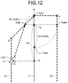
FIG. 10 is a conceptual diagram when the front-side offset point Toft1 of the self-propelled device according to the first embodiment coincides with the goal point B. FIG. 11 is a conceptual diagram when the position P of the self-propelled device according to the first embodiment is ahead of the position illustrated in FIG. 10. FIG. 12 is a conceptual diagram when the position P of the self-propelled device according to the first embodiment is further ahead of the position illustrated in FIG. 11. FIG. 13 is a conceptual diagram when the offset reference point Tp of the self-propelled device according to the first embodiment coincides with the goal point B. FIG. 14 is a conceptual diagram when the position P of the self-propelled device according to the first embodiment is ahead of the position illustrated in FIG. 13. FIG. 15 is a conceptual diagram when the position P of the self-propelled device according to the first embodiment is further ahead of the position illustrated in FIG. 14. FIG. 16 is a conceptual diagram when the position P of the self-propelled device according to the first embodiment coincides with the goal point B.
As illustrated in FIG. 10, when the front-side offset point Toft1 of the self-propelled device 100 coincides with the goal point B, the left target point ToftL coincides with Position b. In other words, the distance on the virtual path 2 from the goal point B to the intersection point of the virtual path 2 and a straight line passing through Position b and which is orthogonal to the virtual path 2 is equal to the first initial offset amount VoftL (refer to FIG. 2).
The front-side offset point Toft1, the offset reference point Tp, and the back-side offset point Toft2 converge to the goal point B. In other words, as illustrated in FIGS. 11 and 12, Expression (1) described above indicates that, after the distance between the offset reference point Tp and the goal point B becomes smaller than the first initial offset amount VoftL (R<VoftL), the locus 3 a of the left target point ToftL moves on a straight line connecting Position b and the goal point B, and when the offset reference point Tp coincides with the goal point B, the left target point ToftL coincides with the goal point B as illustrated in FIG. 13. Thereafter, the position P of the self-propelled device 100 approaches the left target point ToftL at the goal point B as illustrated in FIGS. 14 and 15, the position P of the self-propelled device 100 coincides with the goal point B as illustrated in FIG. 16, and the self-propelled device 100 stops.
In this manner, the self-propelled device 100 according to the first embodiment can constantly travel on the left side of the virtual path 2 from the start point A to the goal point B and reach the goal point B.
In the above-described example, the back-side offset point Toft2 and the right target point ToftR are determined, but no back-side offset point Toft2 nor right target point ToftR may be determined when the self-propelled device 100 is set in advance to travel on the left side of the virtual path 2. In other words, the locus 3 b of the right target point ToftR, which is illustrated in FIGS. 6 to 16, is not necessarily needed when traveling is set to be made on the left side of the virtual path 2.
The following describes, with reference to FIGS. 17 to 24, an example in which the self-propelled device 100 autonomously travels on the right side of the virtual path 2, in other words, autonomously travels on a target traveling path set to the locus 3 b of the target point illustrated in FIG. 2.
FIG. 17 is a conceptual diagram when the position P of the self-propelled device according to the first embodiment coincides with the start point A. FIG. 18 is a conceptual diagram when the position P of the self-propelled device according to the first embodiment is ahead of the position illustrated in FIG. 17. FIG. 19 is a conceptual diagram when the position P of the self-propelled device according to the first embodiment is further ahead of the position illustrated in FIG. 18. FIG. 20 is a conceptual diagram when the self-propelled device according to the first embodiment is in a predetermined zone of a straight region from Position c to Position d illustrated in FIG. 2.
As illustrated in FIG. 17, when the position P of the self-propelled device 100 coincides with the start point A, the right target point ToftR coincides with Position c. In other words, the distance on the virtual path 2 from the start point A to the intersection point of the virtual path 2 and a straight line passing through Position c and which is orthogonal to the virtual path 2 is equal to the initial value Vtp (refer to FIG. 2). As illustrated in FIGS. 18 and 19, the right target point ToftR moves on a straight line connecting Position c and Position d as the position P of the self-propelled device 100 separates from the start point A, and accordingly, the position P of the self-propelled device 100 converges to the locus 3 b of the target point, and as illustrated in FIG. 20, the position P of the self-propelled device 100 is on the locus 3 b of the target point in a straight region from Position c to Position d.
FIG. 21 is a conceptual diagram when the offset reference point Tp of the self-propelled device according to the first embodiment coincides with the goal point B. FIG. 22 is a conceptual diagram when the position P of the self-propelled device according to the first embodiment is ahead of the position illustrated in FIG. 21. FIG. 23 is a conceptual diagram when the back-side offset point Toft2 of the self-propelled device according to the first embodiment coincides with the goal point B. FIG. 24 is a conceptual diagram when the position P of the self-propelled device according to the first embodiment coincides with the goal point B.
As illustrated in FIG. 21, when the offset reference point Tp of the self-propelled device 100 coincides with the goal point B, the right target point ToftR coincides with Position d. In other words, the intersection point of the virtual path 2 and a straight line passing through Position d and which is orthogonal to the virtual path 2 coincides with the goal point B (refer to FIG. 2).
The front-side offset point Toft1, the offset reference point Tp, and the back-side offset point Toft2 converge to the goal point B. In other words, as illustrated in FIG. 22, the right target point ToftR coincides with Position d when the offset reference point Tp has converged to the goal point B. Thereafter, as illustrated in FIG. 23, the back-side offset point Toft2 coincides with the intersection point N on the virtual path 2, and as indicated by Expression (2) described above, after the distance between the back-side offset point Toft2 and the goal point B becomes smaller than the second initial offset amount VoftR (R=Vtp<VoftR), the locus 3 b of the right target point ToftR moves on a straight line connecting Position d and the goal point B. Thereafter, when the intersection point N (the back-side offset point Toft2) on the virtual path 2 coincides with the goal point B, the position P of the self-propelled device 100 coincides with the goal point B as illustrated in FIG. 24, and the self-propelled device 100 stops.
In this manner, the self-propelled device 100 according to the first embodiment can constantly travel the right side of the virtual path 2 from the start point A to the goal point B and reach the goal point B.
In the above-described example, the front-side offset point Toft1 and the left target point ToftL are determined, but no front-side offset point Toft1 nor the left target point ToftL may be determined when the self-propelled device 100 is set in advance to travel on the right side of the virtual path 2. In other words, the locus 3 a of the left target point ToftL, which is illustrated in FIGS. 16 to 24, is not necessarily needed when traveling is set to be made on the right side of the virtual path 2.
As illustrated in FIG. 2, Position a and Position c are determined depending on the initial value Vtp. Thus, when the initial value Vtp is too large, the traveling path of the self-propelled device 100 cannot be effectively set on the left side (or on the right side) in some cases. Position b is determined depending on the first initial offset amount VoftL. In the present embodiment, when the initial value Vtp is smaller than the second initial offset amount VoftR, the right target point cannot be appropriately set near the start point A in some cases. Thus, the initial value Vtp is preferably equivalent to the first initial offset amount VoftL and the second initial offset amount VoftR.
As described above, the method of controlling traveling of the self-propelled device 100 according to the first embodiment includes: a first step of estimating the position of the self-propelled device 100; a second step of determining the intersection point N of the virtual path 2 connecting the start point A and the goal point B and the straight line passing through the position of the self-propelled device 100 and which is orthogonal to the virtual path 2; a third step of determining the offset reference point Tp between the intersection point N and the goal point B on the virtual path 2; a fourth step of determining at least an offset point (the front-side offset point Toft1 or the back-side offset point Toft2) at an offset on one of the goal point B side and the start point A side of the offset reference point Tp on the virtual path 2; a fifth step of determining a target point (the left target point ToftL or the right target point ToftR) reached by rotating the offset point (the front-side offset point Toft1 or the back-side offset point Toft2) by 90° about the offset reference point Tp in the anticlockwise direction; and a sixth step of causing the self-propelled device to travel toward the target point (the left target point ToftL or the right target point ToftR).
The self-propelled device 100 according to the first embodiment includes: the position estimation unit 102 configured to estimate the position of the self-propelled device 100; the travel unit 103 configured to move the self-propelled device 100; and the control unit 101 configured to determine the intersection point N of the virtual path 2 connecting the start point A and the goal point B and the straight line passing through the position of the self-propelled device 100 and which is orthogonal to the virtual path 2, determine the offset reference point Tp between the intersection point N and the goal point B on the virtual path 2, determine at least an offset point (the front-side offset point Toft1 or the back-side offset point Toft2) at an offset on one of the goal point B side and the start point A side of the offset reference point Tp on the virtual path 2, determine a target point (the left target point ToftL or the right target point ToftR) reached by rotating the offset point (the front-side offset point Toft1 or the back-side offset point Toft2) by 90° about the offset reference point Tp in the anticlockwise direction, and control the travel unit 103 so that the self-propelled device 100 travels toward the target point (the left target point ToftL or the right target point ToftR).
The computer program executed by a computer to control traveling of the self-propelled device 100 according to the first embodiment includes: a first step of estimating the position of the self-propelled device 100; a second step of determining the intersection point N of the virtual path 2 connecting the start point A and the goal point B and the straight line passing through the position of the self-propelled device 100 and which is orthogonal to the virtual path 2; a third step of determining the offset reference point Tp between the intersection point N and the goal point B on the virtual path 2; a fourth step of determining at least an offset point (the front-side offset point Toft1 or the back-side offset point Toft2) at an offset on one of the goal point B side and the start point A side of the offset reference point Tp on the virtual path 2; a fifth step of determining a target point (the left target point ToftL or the right target point ToftR) reached by rotating the offset point (the front-side offset point Toft1 or the back-side offset point Toft2) by 90° about the offset reference point Tp in the anticlockwise direction; and a sixth step of causing the self-propelled device to travel toward the target point (the left target point ToftL or the right target point ToftR).
The storage medium stores the travel control computer program executed by a computer and including: a first step of estimating the position of the self-propelled device 100; a second step of determining the intersection point N of the virtual path 2 connecting the start point A and the goal point B and the straight line passing through the position of the self-propelled device 100 and which is orthogonal to the virtual path 2; a third step of determining the offset reference point Tp between the intersection point N and the goal point B on the virtual path 2; a fourth step of determining at least an offset point (the front-side offset point Toft1 or the back-side offset point Toft2) at an offset on one of the goal point B side and the start point A side of the offset reference point Tp on the virtual path 2; a fifth step of determining a target point (the left target point ToftL or the right target point ToftR) reached by rotating the offset point (the front-side offset point Toft1 or the back-side offset point Toft2) by 90° about the offset reference point Tp in the anticlockwise direction; and a sixth step of causing the self-propelled device to travel toward the target point (the left target point ToftL or the right target point ToftR).
With these configurations, the self-propelled device 100 is capable of autonomously traveling on a traveling path at an offset on the left or on the right of one the virtual path 2 without providing, for example, an outgoing path and a returning path between two points.
Moreover, there is no need to generate a plurality of paths, which results in reduction of a load due to path generation.
Second Embodiment
FIG. 25 is a schematic diagram of a region including the virtual path of the self-propelled device according to a second embodiment. Any component same as that in the configuration described above in the first embodiment is denoted by an identical reference sign, and duplicate description thereof is omitted.
The storage unit 105 stores the virtual path 2 generated by the path generation unit 104 (illustrated in FIG. 25). FIG. 25 illustrates an example in which the start point A and the goal point B are set at central parts of both ends of the corridor 1, respectively, and the straight line connecting the start point A and the goal point B is generated as the virtual path 2 of the self-propelled device 100. In FIG. 25, a solid line indicates the virtual path 2 of the self-propelled device 100, and dashed lines illustrate exemplary loci 3 a and 3 b of target points of the self-propelled device 100. Although FIG. 25 illustrates the example in which, for simplification of the following description, the virtual path 2 of the self-propelled device 100 is set to be the straight line connecting the start point A and the goal point B, the virtual path 2 of the self-propelled device 100 is not limited thereto, and for example, the virtual path 2 of the self-propelled device 100 may be bent in accordance with the corridor 1 when the corridor 1 is bent, or the virtual path 2 may be curved in accordance with the corridor 1 when the corridor 1 is curved.
In the example illustrated in FIG. 25, the self-propelled device 100 according to the second embodiment travels toward a target point at an offset by the offset amount R on the left or on the right of the virtual path 2 generated by the path generation unit 104.
The following describes a basic exemplary operation when the loci 3 a and 3 b of the target points illustrated in FIG. 25 are target traveling paths of the self-propelled device 100 according to the second embodiment. FIG. 26 is a conceptual diagram for describing the method of controlling traveling of the self-propelled device according to the second embodiment. FIG. 27 is a flowchart illustrating exemplary travel control processing at the self-propelled device according to the second embodiment. FIG. 28 is a diagram illustrating various kinds of exemplary information stored in the storage unit.
FIG. 26 illustrates an example in which the self-propelled device 100 is on the left side of the virtual path 2. FIG. 28 illustrates an example in which, in addition to the virtual path 2 described above, the storage unit 105 stores, as the various kinds of information D1 necessary for control of the self-propelled device 100, the position information of the start point A, the position information of the goal point B, the traveling path information, the initial value Vtp of the distance from the intersection point N to the offset reference point, and an initial offset amount Voft.
For example, the position information of the start point A and the goal point B stored in the storage unit 105 is input from the operation unit 11 and stored as coordinate information in a region including the virtual path 2.
In the present embodiment, as in the example illustrated in FIG. 28, the traveling path information stored in the storage unit 105 is set to be “+ (plus, positive)” when traveling is made on the left side of the virtual path 2 or “− (minus, negative)” when traveling is made on the right side of the virtual path 2.
The storage unit 105 also stores the initial value Vtp of the distance between the intersection point N of the virtual path 2 and the straight line passing through the position of the self-propelled device 100 and which is orthogonal to the virtual path 2 and the offset reference point Tp provided before the goal point B. The initial value Vtp is assumed to be, for example, 2 m approximately. In the present embodiment, for example, the initial value Vtp is input through the transmission-reception unit 13 and the input-output unit 106 in advance and stored in the storage unit 105 as a discrete value such as numerical data or digital data by the control unit 101. Alternatively, for example, the initial value Vtp may be changed in accordance with the speed of the self-propelled device 100 by the control unit 101. In this case, the speed information of the self-propelled device 100 may be included in the various kinds of information D1 stored in the storage unit 105. The present embodiment is not limited to this method of setting the initial value Vtp.
The storage unit 105 also stores the initial offset amount Voft as the initial value of the offset amount R to the loci 3 a and 3 b of the target points when traveling is made on the left side and right side of the virtual path 2.
In the present embodiment, for example, the initial offset amount Voft is input through the transmission-reception unit 13 and the input-output unit 106 in advance and stored in the storage unit 105 as a discrete value such as numerical data or digital data by the control unit 101. Alternatively, for example, the path generation unit 104 may set the initial offset amount Voft based on the map information stored in the storage unit 105. In this case, for example, the setting may be performed in accordance with various conditions including the width of the corridor 1. Alternatively, the setting may be performed while taking into account clearance when a plurality of self-propelled devices 100 pass by at the corridor 1. More specifically, the initial offset amount Voft can take, for example, the maximum value of W/2 when W represents the width of the corridor 1, but preferably takes a value smaller than W/2, for example, W/4 when the width W of the corridor 1 is restricted by a wall surface. Moreover, each initial offset amount may be, for example, W/8 or 3W/8 when a plurality of self-propelled devices 100 travel side by side on the left side or the right side of the virtual path 2. The present embodiment is not limited to this method of setting the initial offset amount Voft.
In the present embodiment, the initial value Vtp of the distance from the intersection point N to the offset reference point Tp on the virtual path 2, the initial offset amount Voft, and the offset amount R satisfy condition expression (4) below.
Vtp≥Voft≥R  (4)
In the present embodiment, the travel control processing at the self-propelled device 100 according to the second embodiment is performed through execution of the travel control computer program stored in the storage unit 105.
First, the position estimation unit 102 estimates the position P of the self-propelled device 100 (step S201).
The control unit 101 determines the intersection point N of the virtual path 2 and the straight line passing through the position P of the self-propelled device 100 and which is orthogonal to the virtual path 2 (step S202).
Subsequently, the control unit 101 determines the offset reference point Tp separated by the initial value Vtp on the goal point B side from the intersection point N on the virtual path 2 (step S203).
Subsequently, the control unit 101 determines an offset point Toft at an offset by the offset amount R (in this example, the initial offset amount Voft) on the goal point B side from the offset reference point Tp on the virtual path 2 (step S204).
Subsequently, the control unit 101 determines the left target point ToftL reached by rotating the offset point Toft by 90° about the offset reference point Tp in the anticlockwise direction, and determines the right target point ToftR reached by rotating the offset point Toft by 90° about the offset reference point Tp in the clockwise direction (step S205).
Then, the control unit 101 determines whether the traveling path information is “+ (plus, positive)”, in other words, whether traveling is set to be made on the left side of the virtual path 2 (step S206).
When the traveling path information is “+(plus, positive)” (Yes at step S206), the control unit 101 controls the rotation angle of the wheel 103 a of the travel unit 103 so that traveling is made toward the left target point ToftL (step S207), and then returns to step S202.
When the traveling path information is “− (minus, negative)” (No at step S206), the control unit 101 controls the rotation angle of the wheel 103 a of the travel unit 103 so that traveling is made toward the right target point ToftR (step S208), and then returns to step S202.
The following describes, with reference to FIGS. 29 to 39, an example in which the self-propelled device 100 autonomously travels on the left side of the virtual path 2, in other words, autonomously travels on a target traveling path set to the locus 3 a of the target point illustrated in FIG. 25.
FIG. 29 is a conceptual diagram when the position P of the self-propelled device according to the second embodiment coincides with the start point A. FIG. 30 is a conceptual diagram when the position P of the self-propelled device according to the second embodiment is ahead of the position illustrated in FIG. 29. FIG. 31 is a conceptual diagram when the position P of the self-propelled device according to the second embodiment is further ahead of the position illustrated in FIG. 30. FIG. 32 is a conceptual diagram when the self-propelled device according to the second embodiment is in a predetermined zone of the straight region from Position a to Position b illustrated in FIG. 25.
As illustrated in FIG. 29, when the position P of the self-propelled device 100 coincides with the start point A, the left target point ToftL coincides with Position a. In other words, the distance on the virtual path 2 from the start point A to the intersection point of the virtual path 2 and the straight line passing through Position a and which is orthogonal to the virtual path 2 is equal to the initial value Vtp (refer to FIG. 25). As illustrated in FIGS. 30 and 31, the left target point ToftL moves on the straight line connecting Position a and Position b as the position P of the self-propelled device 100 separates from the start point A, and accordingly, the position P of the self-propelled device 100 converges to the locus 3 a of the target point, and as illustrated in FIG. 32, the position P of the self-propelled device 100 is on the locus 3 a of the target point in the straight region from Position a to Position b.
FIG. 33 is a conceptual diagram when the offset point Toft of the self-propelled device according to the second embodiment coincides with the goal point B. FIG. 34 is a conceptual diagram when the position P of the self-propelled device according to the second embodiment is ahead of the position illustrated in FIG. 33. FIG. 35 is a conceptual diagram when the position P of the self-propelled device according to the second embodiment is further ahead of the position illustrated in FIG. 34. FIG. 36 is a conceptual diagram when the offset reference point Tp of the self-propelled device according to the second embodiment coincides with the goal point B. FIG. 37 is a conceptual diagram when the position P of the self-propelled device according to the second embodiment is ahead of the position illustrated in FIG. 36. FIG. 38 is a conceptual diagram when the position P of the self-propelled device according to the second embodiment is further ahead of the position illustrated in FIG. 37. FIG. 39 is a conceptual diagram when the position P of the self-propelled device according to the second embodiment coincides with the goal point B.
As illustrated in FIG. 33, when the offset point Toft of the self-propelled device 100 coincides with the goal point B, the left target point ToftL coincides with Position b. In other words, the distance on the virtual path 2 from the goal point B to the intersection point of the virtual path 2 and the straight line passing through Position b and which is orthogonal to the virtual path 2 is equal to the initial offset amount Voft (refer to FIG. 25).
The offset point Toft and the offset reference point Tp converge to the goal point B. In other words, as illustrated in FIGS. 34 and 35, Expression (4) described above indicates that, after the distance between the offset reference point Tp and the goal point B becomes smaller than the initial offset amount Voft (R<Voft), the locus 3 a of the left target point ToftL moves on the straight line connecting Position b and the goal point B, and when the offset reference point Tp coincides with the goal point B, the left target point ToftL coincides with the goal point B as illustrated in FIG. 36. Thereafter, the position P of the self-propelled device 100 approaches the left target point ToftL at the goal point B as illustrated in FIGS. 37 and 38, the position P of the self-propelled device 100 coincides with the goal point B as illustrated in FIG. 39, and the self-propelled device 100 stops.
In this manner, the self-propelled device 100 according to the second embodiment can constantly travel on the left side of the virtual path 2 from the start point A to the goal point B and reach the goal point B.
In the above-described example, the right target point ToftR is determined, but no right target point ToftR may be determined when the self-propelled device 100 is set in advance to travel on the left side of the virtual path 2. In other words, the locus 3 b of the right target point ToftR, which is illustrated in FIGS. 29 to 39, is not necessarily needed when traveling is set to be made on the left side of the virtual path 2.
The following describes, with reference to FIGS. 40 to 47, an example in which the self-propelled device 100 autonomously travels on the right side of the virtual path 2, in other words, autonomously travels on a target traveling path set to the locus 3 b of the target point, which is illustrated in FIG. 25.
FIG. 40 is a conceptual diagram when the position P of the self-propelled device according to the second embodiment coincides with the start point A. FIG. 41 is a conceptual diagram when the position P of the self-propelled device according to the second embodiment is ahead of the position illustrated in FIG. 40. FIG. 42 is a conceptual diagram when the position P of the self-propelled device according to the second embodiment is further ahead of the position illustrated in FIG. 41. FIG. 43 is a conceptual diagram when the self-propelled device according to the second embodiment is in a predetermined zone of the straight region from Position c to Position d illustrated in FIG. 25.
As illustrated in FIG. 40, when the position P of the self-propelled device 100 coincides with the start point A, the right target point ToftR coincides with Position c. In other words, the distance on the virtual path 2 from the start point A to the intersection point of the virtual path 2 and the straight line passing through Position c and which is orthogonal to the virtual path 2 is equal to the initial value Vtp (refer to FIG. 25). As illustrated in FIGS. 41 and 42, the right target point ToftR moves on the straight line connecting Position c and Position d as the position P of the self-propelled device 100 separates from the start point A, and accordingly, the position P of the self-propelled device 100 converges to the locus 3 b of the target point, and as illustrated in FIG. 43, the position P of the self-propelled device 100 is on the locus 3 b of the target point in the straight region from Position c to Position d.
FIG. 44 is a conceptual diagram when the offset point Toft of the self-propelled device according to the second embodiment coincides with the goal point B. FIG. 45 is a conceptual diagram when the position P of the self-propelled device according to the second embodiment is ahead of the position illustrated in FIG. 44. FIG. 46 is a conceptual diagram when the position P of the self-propelled device according to the second embodiment is further ahead of the position illustrated in FIG. 45. FIG. 47 is a conceptual diagram when the offset reference point Tp of the self-propelled device according to the second embodiment coincides with the goal point B. FIG. 48 is a conceptual diagram when the position P of the self-propelled device according to the second embodiment is ahead of the position illustrated in FIG. 47. FIG. 49 is a conceptual diagram when the position P of the self-propelled device according to the second embodiment is further ahead of the position illustrated in FIG. 48. FIG. 50 is a conceptual diagram when the position P of the self-propelled device according to the second embodiment coincides with the goal point B.
As illustrated in FIG. 44, when the offset point Toft of the self-propelled device 100 coincides with the goal point B, the right target point ToftR coincides with Position d. In other words, the distance on the virtual path 2 from the goal point B to the intersection point of the virtual path 2 and the straight line passing through Position d and which is orthogonal to the virtual path 2 is equal to the initial offset amount Voft (refer to FIG. 25).
The offset point Toft and the offset reference point Tp converge to the goal point B. In other words, as illustrated in FIGS. 45 and 46, Expression (4) described above indicates that, after the distance between the offset reference point Tp and the goal point B becomes smaller than the initial offset amount Voft (R<Voft), the locus 3 b of the right target point ToftR moves on the straight line connecting Position d and the goal point B, and when the offset reference point Tp coincides with the goal point B, the right target point ToftR coincides with the goal point B as illustrated in FIG. 47. Thereafter, the position P of the self-propelled device 100 approaches the right target point ToftR at the goal point B as illustrated in FIGS. 48 and 49, the position P of the self-propelled device 100 coincides with the goal point B as illustrated in FIG. 50, and the self-propelled device 100 stops.
In this manner, the self-propelled device 100 according to the second embodiment can constantly travel the right side of the virtual path 2 from the start point A to the goal point B and reach the goal point B.
In the above-described example, the left target point ToftL is determined, but no left target point ToftL may be determined when the self-propelled device 100 is set in advance to travel on the right side of the virtual path 2. In other words, the locus 3 a of the left target point ToftL, which is illustrated in FIGS. 40 to 50, is not necessarily needed when traveling is set to be made on the right side of the virtual path 2.
As illustrated in FIG. 25, Position a and Position c are determined depending on the initial value Vtp. Thus, when the initial value Vtp is too large, the traveling path of the self-propelled device 100 cannot be effectively set on the left side (or on the right side) in some cases. Position b and Position d are determined depending on the initial offset amount Voft. Thus, the initial value Vtp is preferably equivalent to the initial offset amount Voft.
As described above, the method of controlling traveling of the self-propelled device 100 according to the second embodiment includes: a first step of estimating the position of the self-propelled device 100; a second step of determining the intersection point N of the virtual path 2 connecting the start point A and the goal point B and the straight line passing through the position of the self-propelled device 100 and which is orthogonal to the virtual path 2; a third step of determining the offset reference point Tp between the intersection point N and the goal point B on the virtual path 2; a fourth step of determining the offset point Toft at an offset on the goal point B side from the offset reference point Tp on the virtual path 2; a fifth step of determining at least a target point (the left target point ToftL or the right target point ToftR) reached by rotating the offset point Toft by 90° about the offset reference point Tp in one of the anticlockwise direction and the clockwise direction; and a sixth step of causing the self-propelled device to travel toward the target point (the left target point ToftL or the right target point ToftR).
The self-propelled device 100 according to the second embodiment includes: the position estimation unit 102 configured to estimate the position of the self-propelled device 100; the travel unit 103 configured to move the self-propelled device 100; and the control unit 101 configured to determine the intersection point N of the virtual path 2 connecting the start point A and the goal point B and the straight line passing through the position of the self-propelled device 100 and which is orthogonal to the virtual path 2, determine the offset reference point Tp between the intersection point N and the goal point B on the virtual path 2, determine the offset point Toft at an offset on the goal point B side from the offset reference point Tp on the virtual path 2, determine at least a target point (the left target point ToftL or the right target point ToftR) reached by rotating the offset point Toft by 90° about the offset reference point Tp in one of the anticlockwise direction and the clockwise direction, and control the travel unit 103 so that the self-propelled device 100 travels toward the target point (the left target point ToftL or the right target point ToftR).
The computer program executed by a computer to control traveling of the self-propelled device 100 according to the second embodiment includes: a first step of estimating the position of the self-propelled device 100; a second step of determining the intersection point N of the virtual path 2 connecting the start point A and the goal point B and the straight line passing through the position of the self-propelled device 100 and which is orthogonal to the virtual path 2; a third step of determining the offset reference point Tp between the intersection point N and the goal point B on the virtual path 2; a fourth step of determined the offset point Toft at an offset on the goal point B side from the offset reference point Tp on the virtual path 2; a fifth step of determining at least a target point (the left target point ToftL or the right target point ToftR) reached by rotating the offset point Toft by 90° about the offset reference point Tp in one of the anticlockwise direction and the clockwise direction; and a sixth step of causing the self-propelled device to travel toward the target point (the left target point ToftL or the right target point ToftR).
The storage medium stores the travel control computer program executed by a computer and including: a first step of estimating the position of the self-propelled device 100; a second step of determining the intersection point N of the virtual path 2 connecting the start point A and the goal point B and the straight line passing through the position of the self-propelled device 100 and which is orthogonal to the virtual path 2; a third step of determining the offset reference point Tp between the intersection point N and the goal point B on the virtual path 2; a fourth step of determining the offset point Toft at an offset on the goal point B side from the offset reference point Tp on the virtual path 2; a fifth step of determining at least a target point (the left target point ToftL or the right target point ToftR) reached by rotating the offset point Toft by 90° about the offset reference point Tp in one of the anticlockwise direction and the clockwise direction; and a sixth step of causing the self-propelled device to travel toward the target point (the left target point ToftL or the right target point ToftR).
With these configurations, the self-propelled device 100 is capable of autonomously traveling on a traveling path at an offset on the left or on the right of one the virtual path 2 without providing, for example, an outgoing path and a returning path between two points.
Moreover, there is no need to generate a plurality of paths, which results in reduction of a load due to path generation.
In this manner, the above-described embodiments provide a self-propelled device capable of autonomously traveling on the left side or right side of one virtual path connecting two points, a method of controlling traveling of the self-propelled device, and a computer program of controlling traveling of the self-propelled device.
REFERENCE SIGNS LIST
1 corridor
2 virtual path
3 a, 3 b target point loci
11 operation unit
12 display unit
13 transmission-reception unit
100 self-propelled device
101 control unit
102 position estimation unit
103 travel unit
103 a wheel
104 path generation unit
105 storage unit
106 input-output unit
R offset amount
Toft offset point
Toft1 front-side offset point
Toft2 back-side offset point
ToftL left target point
ToftR right target point
Tp offset reference point
Voft initial offset amount
VoftL first initial offset amount
VoftR second initial offset amount
Vtp initial value

Claims (21)

The invention claimed is:
1. A method of controlling traveling of a self-propelled device capable of autonomously traveling from a start point to a goal point, the method comprising:
a first step of estimating a position of the self-propelled device;
a second step of determining an intersection point of a virtual path and a straight line, the virtual path connecting the start point and the goal point, and the straight line passing through the position of the self-propelled device and which is orthogonal to the virtual path;
a third step of determining an offset reference point between the intersection point and the goal point on the virtual path;
a fourth step of determining at least an offset point at an offset on one of a side of the goal point and a side of the start point of the offset reference point on the virtual path;
a fifth step of determining at least a target point reached by rotating the offset point by 90° about the offset reference point in one of an anticlockwise direction and a clockwise direction; and
a sixth step of causing the self-propelled device to travel toward the target point.
2. The method of controlling traveling of the self-propelled device according to claim 1, wherein the fifth step determines a target point reached by rotating the offset point by 90° about the offset reference point in the anticlockwise direction.
3. The method of controlling traveling of the self-propelled device according to claim 2, wherein, when the self-propelled device is set in advance to travel on a left side of the virtual path:
the fourth step determines at least a front-side offset point at an offset on the side of the goal point of the offset reference point on the virtual path;
the fifth step determines a left target point reached by rotating the front-side offset point by 90° about the offset reference point in the anticlockwise direction; and
the sixth step causes the self-propelled device to travel toward the left target point.
4. The method of controlling traveling of the self-propelled device according to claim 2, wherein, when the self-propelled device is set in advance to travel on a right side of the virtual path:
the fourth step determines at least a back-side offset point at an offset on the side of the start point of the offset reference point on the virtual path;
the fifth step determines a right target point reached by rotating the back-side offset point by 90° about the offset reference point in the anticlockwise direction; and
the sixth step causes the self-propelled device to travel toward the right target point.
5. The method of controlling traveling of the self-propelled device according to claim 3, wherein a distance from the offset reference point to the front-side offset point is equal to or smaller than a distance from the intersection point to the offset reference point on the virtual path.
6. The method of controlling traveling of the self-propelled device according to claim 4, wherein a distance from the offset reference point to the back-side offset point is equal to or smaller than a distance from the intersection point to the offset reference point on the virtual path.
7. The method of controlling traveling of the self-propelled device according to claim 1, wherein the fourth step determines an offset point at an offset on the side of the goal point of the offset reference point on the virtual path.
8. The method of controlling traveling of the self-propelled device according to claim 7, wherein, when the self-propelled device is set in advance to travel on a left side of the virtual path:
the fifth step determines a left target point reached by rotating the offset point by 90° about the offset reference point in the anticlockwise direction; and
the sixth step causes the self-propelled device to travel toward the left target point.
9. The method of controlling traveling of the self-propelled device according to claim 7, wherein, when the self-propelled device is set in advance to travel on a right side of the virtual path:
the fifth step determines a right target point reached by rotating the offset point by 90° about the offset reference point in the clockwise direction; and
the sixth step causes the self-propelled device to travel toward the right target point.
10. The method of controlling traveling of the self-propelled device according to claim 7, wherein a distance from the offset reference point to the offset point is equal to or smaller than a distance from the intersection point to the offset reference point on the virtual path.
11. The method of controlling traveling of the self-propelled device according to claim 1, wherein the offset reference point and the offset point converge to the goal point as the self-propelled device approaches the goal point.
12. A self-propelled device capable of autonomously traveling from a start point to a goal point, the self-propelled device comprising:
a wheel, a drive device, and a sensor, the wheel, the drive device, and the sensor configured to move the self-propelled device; and
a control unit configured to:
estimate a position of the self-propelled device,
determine an intersection point of a virtual path and a straight line, the virtual path connecting the start point and the goal point, and the straight line passing through the position of the self-propelled device and which is orthogonal to the virtual path,
determine an offset reference point between the intersection point and the goal point on the virtual path,
determine at least an offset point at an offset on one of the side of the goal point and the side of the start point of the offset reference point on the virtual path,
determine at least a target point reached by rotating the offset point by 90° about the offset reference point in one of an anticlockwise direction and a clockwise direction, and
control the travel circuit so that the self-propelled device travels toward the target point.
13. The self-propelled device according to claim 12, wherein, when the self-propelled device is set in advance to travel on a left side of the virtual path, the control unit determines at least a front-side offset point at an offset on the side of the goal point of the offset reference point on the virtual path, determines a left target point reached by rotating the front-side offset point by 90° about the offset reference point in the anticlockwise direction, and controls the travel circuit so that the self-propelled device travels toward the left target point.
14. The self-propelled device according to claim 12, wherein, when the self-propelled device is set in advance to travel on a right side of the virtual path, the control unit determines at least a back-side offset point at an offset on the side of the start point of the offset reference point on the virtual path, determines a right target point reached by rotating the back-side offset point by 90° about the offset reference point in the anticlockwise direction, and controls the travel circuit so that the self-propelled device travels toward the right target point.
15. The self-propelled device according to claim 13, wherein a distance from the offset reference point to the front-side offset point is equal to or smaller than a distance from the intersection point to the offset reference point on the virtual path.
16. The self-propelled device according to claim 14, wherein a distance from the offset reference point to the back-side offset point is equal to or smaller than a distance from the intersection point to the offset reference point on the virtual path.
17. The self-propelled device according to claim 12, wherein, when the self-propelled device is set in advance to travel on a left side of the virtual path, the control unit determines an offset point at an offset on the side of the goal point of the offset reference point on the virtual path, determines a left target point reached by rotating the offset point by 90° about the offset reference point in the anticlockwise direction, and controls the travel circuit so that the self-propelled device travels toward the left target point.
18. The self-propelled device according to claim 12, wherein, when the self-propelled device is set in advance to travel on a right side of the virtual path, the control unit determines an offset point at an offset on the side of the goal point of the offset reference point on the virtual path, determines a right target point reached by rotating the offset point by 90° about the offset reference point in the clockwise direction, and controls the travel circuit so that the self-propelled device travels toward the right target point.
19. The self-propelled device according to claim 17, wherein a distance from the offset reference point to the offset point is equal to or smaller than a distance from the intersection point to the offset reference point on the virtual path.
20. The self-propelled device according to claim 12, wherein the offset reference point and the offset point converge to the goal point as the self-propelled device approaches the goal point.
21. A non-transitory computer readable recording medium storing therein a control program executed by a processor to control traveling of a self-propelled device capable of autonomously traveling from a start point to a goal point, the control program causing the processor to perform:
a first step of estimating a position of the self-propelled device;
a second step of determining an intersection point of a virtual path and a straight line, the virtual path connecting the start point and the goal point, and the straight line passing through the position of the self-propelled device and which is orthogonal to the virtual path;
a third step of determining an offset reference point between the intersection point and the goal point on the virtual path;
a fourth step of determining at least an offset point at an offset on one of the side of the goal point and the side of the start point of the offset reference point on the virtual path;
a fifth step of determining at least a target point reached by rotating the offset point by 90° about the offset reference point in one of an anticlockwise direction and a clockwise direction; and
a sixth step of causing the self-propelled device to travel toward the target point.
US16/610,319 2017-09-08 2018-08-22 Self-propelled device, and method and travel control computer program of controlling traveling of self-propelled device Active US10935386B2 (en)

Applications Claiming Priority (7)

Application Number Priority Date Filing Date Title
JP2017173390 2017-09-08
JP2017173389 2017-09-08
JPJP2017-173390 2017-09-08
JP2017-173390 2017-09-08
JPJP2017-173389 2017-09-08
JP2017-173389 2017-09-08
PCT/JP2018/030957 WO2019049664A1 (en) 2017-09-08 2018-08-22 Self-propelled device, and travelling control method and travelling control program of self-propelled device

Publications (2)

Publication Number Publication Date
US20200080850A1 US20200080850A1 (en) 2020-03-12
US10935386B2 true US10935386B2 (en) 2021-03-02

Family

ID=65634022

Family Applications (1)

Application Number Title Priority Date Filing Date
US16/610,319 Active US10935386B2 (en) 2017-09-08 2018-08-22 Self-propelled device, and method and travel control computer program of controlling traveling of self-propelled device

Country Status (5)

Country Link
US (1) US10935386B2 (en)
EP (1) EP3680742B1 (en)
JP (1) JP6540917B1 (en)
CN (1) CN111095152B (en)
WO (1) WO2019049664A1 (en)

Families Citing this family (3)

* Cited by examiner, † Cited by third party
Publication number Priority date Publication date Assignee Title
KR102337531B1 (en) * 2020-07-08 2021-12-09 네이버랩스 주식회사 Method and system for specifying node for robot path plannig
CN114454172B (en) * 2020-09-25 2024-04-23 武汉联影智融医疗科技有限公司 Control method of tail end adapter of mechanical arm
JP2024039811A (en) * 2022-09-12 2024-03-25 ヤンマーホールディングス株式会社 Route generation method, route generation system, and route generation program

Citations (9)

* Cited by examiner, † Cited by third party
Publication number Priority date Publication date Assignee Title
JPS61251911A (en) 1985-04-30 1986-11-08 Komatsu Ltd Method for guiding unattended moving body
JPH02311909A (en) 1989-05-29 1990-12-27 Shinko Electric Co Ltd Mobile robot
US5568030A (en) 1989-04-25 1996-10-22 Shinko Electric Co., Ltd. Travel control method, travel control device, and mobile robot for mobile robot systems
JP2011107984A (en) 2009-11-17 2011-06-02 Toyota Motor Corp Route search system, method and program, and mobile body
JP2012094027A (en) 2010-10-28 2012-05-17 Toyota Motor Corp Mobile body
JP2015121928A (en) 2013-12-24 2015-07-02 トヨタ自動車株式会社 Autonomous mobile robot control method
US20170008521A1 (en) * 2015-02-10 2017-01-12 Mobileye Vision Technologies Ltd. Autonomous vehicle speed calibration
US20170371340A1 (en) * 2016-06-27 2017-12-28 Mobileye Vision Technologies Ltd. Controlling host vehicle based on detected spacing between stationary vehicles
US20180101177A1 (en) * 2016-10-11 2018-04-12 Mobileye Vision Technologies Ltd. Navigating a vehicle based on a detected barrier

Family Cites Families (4)

* Cited by examiner, † Cited by third party
Publication number Priority date Publication date Assignee Title
JP5462536B2 (en) * 2009-06-30 2014-04-02 日立オートモティブシステムズ株式会社 Route guidance server device, navigation device, route guidance system, and route guidance method
DE102012207269A1 (en) * 2012-05-02 2013-11-07 Kuka Laboratories Gmbh Method for operating driverless transport vehicle, involves automatically moving driverless transport vehicle along real track based on virtual track and determining current position of vehicle with respect to virtual map
DE102013207895A1 (en) * 2013-04-30 2014-10-30 Kuka Laboratories Gmbh Driverless transport vehicle, system with a computer and a driverless transport vehicle, method for operating a driverless transport vehicle
CN108369418B (en) * 2015-09-22 2021-09-21 蓝宝机噐人技术股份公司 Virtual line following and improvement method for autonomous vehicles

Patent Citations (9)

* Cited by examiner, † Cited by third party
Publication number Priority date Publication date Assignee Title
JPS61251911A (en) 1985-04-30 1986-11-08 Komatsu Ltd Method for guiding unattended moving body
US5568030A (en) 1989-04-25 1996-10-22 Shinko Electric Co., Ltd. Travel control method, travel control device, and mobile robot for mobile robot systems
JPH02311909A (en) 1989-05-29 1990-12-27 Shinko Electric Co Ltd Mobile robot
JP2011107984A (en) 2009-11-17 2011-06-02 Toyota Motor Corp Route search system, method and program, and mobile body
JP2012094027A (en) 2010-10-28 2012-05-17 Toyota Motor Corp Mobile body
JP2015121928A (en) 2013-12-24 2015-07-02 トヨタ自動車株式会社 Autonomous mobile robot control method
US20170008521A1 (en) * 2015-02-10 2017-01-12 Mobileye Vision Technologies Ltd. Autonomous vehicle speed calibration
US20170371340A1 (en) * 2016-06-27 2017-12-28 Mobileye Vision Technologies Ltd. Controlling host vehicle based on detected spacing between stationary vehicles
US20180101177A1 (en) * 2016-10-11 2018-04-12 Mobileye Vision Technologies Ltd. Navigating a vehicle based on a detected barrier

Non-Patent Citations (1)

* Cited by examiner, † Cited by third party
Title
International Search Report for PCT/JP2018/030957 dated, Nov. 6, 2018 (PCT/ISA/210).

Also Published As

Publication number Publication date
JP6540917B1 (en) 2019-07-10
US20200080850A1 (en) 2020-03-12
CN111095152A (en) 2020-05-01
EP3680742A1 (en) 2020-07-15
EP3680742B1 (en) 2022-10-05
CN111095152B (en) 2023-12-01
JPWO2019049664A1 (en) 2019-11-07
WO2019049664A1 (en) 2019-03-14
EP3680742A4 (en) 2021-04-14

Similar Documents

Publication Publication Date Title
CN110260867B (en) Method, equipment and device for determining and correcting neutral position in robot navigation
US10935386B2 (en) Self-propelled device, and method and travel control computer program of controlling traveling of self-propelled device
CN110488843B (en) Obstacle avoidance method, mobile robot, and computer-readable storage medium
CN106933223B (en) Autonomous navigation method and system for robot
US11797023B2 (en) Controller, control method, and program
CN108827278A (en) Air navigation aid and equipment
WO2023036044A1 (en) Global path planning method, motion control method and computer program product
CN114771551B (en) Automatic driving vehicle track planning method and device and automatic driving vehicle
WO2023151548A1 (en) Navigation method and apparatus, and program and computer-readable storage medium
JP2007328486A (en) Moving robot
JP2008021178A (en) Autonomous mobile robot, autonomous locomotion method and autonomous locomotion information processing program
US20220009101A1 (en) Control device, control method, and non-transitory recording medium
US20190286159A1 (en) Position estimation system, position detection method, and program
WO2021027966A1 (en) Traveling method, traveling device, and storage medium
KR102183830B1 (en) The route control apparatus of automatic guided vehicle and route controlling method of thereof
WO2023124339A1 (en) Path planning method, motion control method and computer program product
CN111114542A (en) Curve driving control method, device, equipment and medium for automatic driving vehicle
US20200409388A1 (en) Controller, control method, and program
US20190265698A1 (en) Systems and methods for tele-present recovery of self-driving vehicles
US11531344B2 (en) Autonomous running device, running control method for autonomous running device, and running control program of autonomous running device
EP3936964A1 (en) Map creation device, map creation method, and program
JP2021143830A (en) Information processing device and information processing method
CN112577503B (en) Path planning method, device and equipment for vehicle starting point area
CN114153211A (en) Method, device and equipment for scheduling multi-robot over-narrow channel and storage medium
CN112631267B (en) Automatic walking equipment control method and automatic walking equipment

Legal Events

Date Code Title Description
AS Assignment

Owner name: NSK LTD., JAPAN

Free format text: ASSIGNMENT OF ASSIGNORS INTEREST;ASSIGNORS:MORI, MAYUKO;TANOUE, MASAAKI;TOBITA, KAZUTERU;AND OTHERS;SIGNING DATES FROM 20190916 TO 20191009;REEL/FRAME:050893/0411

FEPP Fee payment procedure

Free format text: ENTITY STATUS SET TO UNDISCOUNTED (ORIGINAL EVENT CODE: BIG.); ENTITY STATUS OF PATENT OWNER: LARGE ENTITY

STPP Information on status: patent application and granting procedure in general

Free format text: DOCKETED NEW CASE - READY FOR EXAMINATION

STPP Information on status: patent application and granting procedure in general

Free format text: RESPONSE TO NON-FINAL OFFICE ACTION ENTERED AND FORWARDED TO EXAMINER

STPP Information on status: patent application and granting procedure in general

Free format text: NOTICE OF ALLOWANCE MAILED -- APPLICATION RECEIVED IN OFFICE OF PUBLICATIONS

STCF Information on status: patent grant

Free format text: PATENTED CASE