US10926263B2 - Methods and apparatus to mitigate bubble formation in a liquid - Google Patents
Methods and apparatus to mitigate bubble formation in a liquid Download PDFInfo
- Publication number
- US10926263B2 US10926263B2 US16/107,826 US201816107826A US10926263B2 US 10926263 B2 US10926263 B2 US 10926263B2 US 201816107826 A US201816107826 A US 201816107826A US 10926263 B2 US10926263 B2 US 10926263B2
- Authority
- US
- United States
- Prior art keywords
- sidewall
- baffle
- container
- end wall
- wall
- Prior art date
- Legal status (The legal status is an assumption and is not a legal conclusion. Google has not performed a legal analysis and makes no representation as to the accuracy of the status listed.)
- Active, expires
Links
Images


Classifications
-
- B—PERFORMING OPERATIONS; TRANSPORTING
- B01—PHYSICAL OR CHEMICAL PROCESSES OR APPARATUS IN GENERAL
- B01L—CHEMICAL OR PHYSICAL LABORATORY APPARATUS FOR GENERAL USE
- B01L3/00—Containers or dishes for laboratory use, e.g. laboratory glassware; Droppers
- B01L3/52—Containers specially adapted for storing or dispensing a reagent
-
- B01F11/0002—
-
- B01F11/0005—
-
- B01F11/0008—
-
- B—PERFORMING OPERATIONS; TRANSPORTING
- B01—PHYSICAL OR CHEMICAL PROCESSES OR APPARATUS IN GENERAL
- B01F—MIXING, e.g. DISSOLVING, EMULSIFYING OR DISPERSING
- B01F29/00—Mixers with rotating receptacles
- B01F29/30—Mixing the contents of individual packages or containers, e.g. by rotating tins or bottles
- B01F29/32—Containers specially adapted for coupling to rotating frames or the like; Coupling means therefor
- B01F29/321—Containers specially adapted for coupling to rotating frames or the like; Coupling means therefor of test-tubes or the like
-
- B—PERFORMING OPERATIONS; TRANSPORTING
- B01—PHYSICAL OR CHEMICAL PROCESSES OR APPARATUS IN GENERAL
- B01F—MIXING, e.g. DISSOLVING, EMULSIFYING OR DISPERSING
- B01F29/00—Mixers with rotating receptacles
- B01F29/30—Mixing the contents of individual packages or containers, e.g. by rotating tins or bottles
- B01F29/34—Constructional details of holders for the individual packages or containers
-
- B—PERFORMING OPERATIONS; TRANSPORTING
- B01—PHYSICAL OR CHEMICAL PROCESSES OR APPARATUS IN GENERAL
- B01F—MIXING, e.g. DISSOLVING, EMULSIFYING OR DISPERSING
- B01F29/00—Mixers with rotating receptacles
- B01F29/40—Parts or components, e.g. receptacles, feeding or discharging means
- B01F29/401—Receptacles, e.g. provided with liners
- B01F29/402—Receptacles, e.g. provided with liners characterised by the relative disposition or configuration of the interior of the receptacles
- B01F29/4022—Configuration of the interior
- B01F29/40221—Configuration of the interior provided with baffles, plates or bars on the wall or the bottom
-
- B—PERFORMING OPERATIONS; TRANSPORTING
- B01—PHYSICAL OR CHEMICAL PROCESSES OR APPARATUS IN GENERAL
- B01F—MIXING, e.g. DISSOLVING, EMULSIFYING OR DISPERSING
- B01F31/00—Mixers with shaking, oscillating, or vibrating mechanisms
- B01F31/10—Mixers with shaking, oscillating, or vibrating mechanisms with a mixing receptacle rotating alternately in opposite directions
-
- B—PERFORMING OPERATIONS; TRANSPORTING
- B01—PHYSICAL OR CHEMICAL PROCESSES OR APPARATUS IN GENERAL
- B01F—MIXING, e.g. DISSOLVING, EMULSIFYING OR DISPERSING
- B01F31/00—Mixers with shaking, oscillating, or vibrating mechanisms
- B01F31/20—Mixing the contents of independent containers, e.g. test tubes
- B01F31/201—Holders therefor
-
- B01F9/002—
-
- B01F9/003—
-
- B—PERFORMING OPERATIONS; TRANSPORTING
- B01—PHYSICAL OR CHEMICAL PROCESSES OR APPARATUS IN GENERAL
- B01L—CHEMICAL OR PHYSICAL LABORATORY APPARATUS FOR GENERAL USE
- B01L3/00—Containers or dishes for laboratory use, e.g. laboratory glassware; Droppers
- B01L3/50—Containers for the purpose of retaining a material to be analysed, e.g. test tubes
- B01L3/508—Containers for the purpose of retaining a material to be analysed, e.g. test tubes rigid containers not provided for above
- B01L3/5082—Test tubes per se
-
- G—PHYSICS
- G01—MEASURING; TESTING
- G01N—INVESTIGATING OR ANALYSING MATERIALS BY DETERMINING THEIR CHEMICAL OR PHYSICAL PROPERTIES
- G01N35/00—Automatic analysis not limited to methods or materials provided for in any single one of groups G01N1/00 - G01N33/00; Handling materials therefor
- G01N35/10—Devices for transferring samples or any liquids to, in, or from, the analysis apparatus, e.g. suction devices, injection devices
- G01N35/1002—Reagent dispensers
-
- B01F2009/0092—
-
- B—PERFORMING OPERATIONS; TRANSPORTING
- B01—PHYSICAL OR CHEMICAL PROCESSES OR APPARATUS IN GENERAL
- B01L—CHEMICAL OR PHYSICAL LABORATORY APPARATUS FOR GENERAL USE
- B01L2200/00—Solutions for specific problems relating to chemical or physical laboratory apparatus
- B01L2200/06—Fluid handling related problems
- B01L2200/0684—Venting, avoiding backpressure, avoid gas bubbles
-
- B—PERFORMING OPERATIONS; TRANSPORTING
- B01—PHYSICAL OR CHEMICAL PROCESSES OR APPARATUS IN GENERAL
- B01L—CHEMICAL OR PHYSICAL LABORATORY APPARATUS FOR GENERAL USE
- B01L2300/00—Additional constructional details
- B01L2300/08—Geometry, shape and general structure
- B01L2300/0848—Specific forms of parts of containers
- B01L2300/0851—Bottom walls
-
- B—PERFORMING OPERATIONS; TRANSPORTING
- B01—PHYSICAL OR CHEMICAL PROCESSES OR APPARATUS IN GENERAL
- B01L—CHEMICAL OR PHYSICAL LABORATORY APPARATUS FOR GENERAL USE
- B01L2400/00—Moving or stopping fluids
- B01L2400/08—Regulating or influencing the flow resistance
- B01L2400/084—Passive control of flow resistance
- B01L2400/086—Passive control of flow resistance using baffles or other fixed flow obstructions
-
- G—PHYSICS
- G01—MEASURING; TESTING
- G01N—INVESTIGATING OR ANALYSING MATERIALS BY DETERMINING THEIR CHEMICAL OR PHYSICAL PROPERTIES
- G01N35/00—Automatic analysis not limited to methods or materials provided for in any single one of groups G01N1/00 - G01N33/00; Handling materials therefor
- G01N2035/00465—Separating and mixing arrangements
- G01N2035/00524—Mixing by agitating sample carrier
-
- G—PHYSICS
- G01—MEASURING; TESTING
- G01N—INVESTIGATING OR ANALYSING MATERIALS BY DETERMINING THEIR CHEMICAL OR PHYSICAL PROPERTIES
- G01N35/00—Automatic analysis not limited to methods or materials provided for in any single one of groups G01N1/00 - G01N33/00; Handling materials therefor
- G01N35/02—Automatic analysis not limited to methods or materials provided for in any single one of groups G01N1/00 - G01N33/00; Handling materials therefor using a plurality of sample containers moved by a conveyor system past one or more treatment or analysis stations
- G01N35/04—Details of the conveyor system
- G01N2035/0439—Rotary sample carriers, i.e. carousels
-
- G—PHYSICS
- G01—MEASURING; TESTING
- G01N—INVESTIGATING OR ANALYSING MATERIALS BY DETERMINING THEIR CHEMICAL OR PHYSICAL PROPERTIES
- G01N35/00—Automatic analysis not limited to methods or materials provided for in any single one of groups G01N1/00 - G01N33/00; Handling materials therefor
- G01N35/10—Devices for transferring samples or any liquids to, in, or from, the analysis apparatus, e.g. suction devices, injection devices
- G01N35/1009—Characterised by arrangements for controlling the aspiration or dispense of liquids
- G01N2035/1025—Fluid level sensing
Definitions
- This disclosure relates generally to fluid analyzers and, more particularly, to methods and apparatus mitigate bubble formation in a liquid.
- Automated analyzers are used to analyze samples including biological material gathered from patients for diagnostic purposes. Generally, analysis of a sample involves reacting the sample with one or more reagents in a liquid container. Some automated analyzers store reagents in containers on a carousel. When a particular reagent is needed, the carousel is rotated to move the container holding the reagent to be adjacent an aspirating/dispensing device. The carousel moves by accelerating and decelerating, which subjects the reagents to rotational forces that could cause bubbles to form in the liquid.
- FIG. 1 illustrates an example cartridge that is holding a plurality of example containers and which is coupled to a portion of an example carousel.
- FIG. 2 is a cross-sectional view of a first container of the example cartridge of FIG. 1 taken along the A-A line of FIG. 1 .
- FIG. 3 is a cross-sectional view of a second container of the example cartridge of FIG. 1 taken along the A-A line of FIG. 1 .
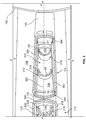
- FIG. 4 is a side, cross-sectional view of the example cartridge of FIG. 1 taken along the B-B line of FIG. 1 when the example cartridge is substantially stationary.
- FIG. 5 is a side, cross-sectional view of the example cartridge of FIG. 1 taken along the B-B line of FIG. 1 when the example cartridge is rotating.
- FIG. 6 is a graph showing a velocity of the example cartridge on the carousel of FIG. 1 over a period of time.
- FIG. 7 is a top, cross-sectional view of an alternative example container disclosed herein.
- FIG. 8 is a perspective, cross-sectional view of the example container of FIG. 7 taken along the C-C line of FIG. 7 .
- FIG. 9 is a flowchart representative of an example method disclosed herein.
- any part e.g., a layer, film, area, or plate
- any part is in any way positioned on (e.g., positioned on, located on, disposed on, or formed on, etc.) another part
- the referenced part is either in contact with the other part, or that the referenced part is above the other part with one or more intermediate part(s) located therebetween.
- Stating that any part is in contact with another part means that there is no intermediate part between the two parts.
- a liquid reagent in a container of an automatic diagnostic analyzer which may be, for example, a clinical chemistry analyzer, an immunoassay analyzer, and/or a hematology analyzer.
- Some reagents used in automatic diagnostic analyzers include a liquid and one or more surfactants (e.g., detergents).
- Automatic diagnostic analyzers typically rotate reagent containers or bottles about an axis and/or in an oscillating manner, and the rotation, acceleration and/or deceleration imparts forces on the contents of the containers, which may agitate the contents of the containers.
- Example containers disclosed herein use baffles to mitigate (e.g., reduce and/or substantially minimize) bubble formation in the liquid and enable the liquid to quickly settle after the containers decelerate to a substantially stationary state.
- Some example baffles disclosed herein extend from bottom walls of the containers and are spaced apart from sidewalls, end walls, and top walls of the containers.
- the baffles are c-shaped and have concave portions facing an axis of rotation of the containers.
- the top walls define throats and crowns.
- the containers have rounded-rectangular shapes that provide greater space utilization in diagnostic systems than many known container configurations.
- analyzers can have an increased load capacity and/or smaller size, compared to many known systems.
- the example containers can be created with fabrication techniques such as, for example, injection molding and/or laser welding, which reduce costs compared to the fabrication techniques used to create many known container configurations.
- an example apparatus that includes a reagent container having a first sidewall and a second sidewall opposite the first sidewall.
- the example container further includes a top wall coupled to the first sidewall and the second sidewall.
- the example container also includes a bottom wall opposite the top wall, and the bottom wall is coupled to the first sidewall and the second sidewall.
- the example container also includes a first baffle extending from the bottom wall. The example first baffle is spaced apart from the first sidewall, the second sidewall, and the top wall.
- the apparatus also includes a second baffle extending from the bottom wall.
- the second baffle may be spaced apart from the first sidewall, the second sidewall, the top wall and the first baffle.
- the first baffle has a first height and the second baffle has a second height greater than the first height.
- the first baffle and the second baffle may be positioned radially relative to an axis of rotation of the apparatus.
- the first baffle has a c-shaped cross-section.
- the top wall includes a first portion and a second portion.
- the first portion may be at a first height relative to the bottom wall and the second portion may be at a second height relative to the bottom wall greater than the first height.
- the first portion of the top wall defines an aperture.
- the second portion of the top wall defines a crown, and liquid is to flow around the first baffle and into the crown when the apparatus is rotated.
- the apparatus also includes a carrier, and the container is removably coupled to the carrier.
- the bottom wall is curved.
- the apparatus also includes a first curved end wall and a second curved end wall opposite the first curved end wall. The first end wall and the second end wall may couple the first sidewall and the second sidewall.
- Another example apparatus disclosed herein includes a bottom wall, a first baffle cantilevered from the bottom wall, and a second baffle cantilevered from the bottom wall.
- the example first baffle is spaced apart from the example second baffle, and the first baffle and the second baffle are positioned radially relative to an axis of rotation of the apparatus.
- the first baffle is curved.
- the first baffle has a c-shaped cross-section and is oriented such that a concave portion of the c-shaped cross-section faces the axis of rotation of the apparatus.
- the second baffle has a c-shaped cross-section and is oriented such that a concave portion of the c-shaped cross-section of the second baffle faces the axis of rotation of the apparatus.
- Another example apparatus disclosed herein includes a bottom wall, a first sidewall coupled to the bottom wall, and a top wall coupled to the sidewall.
- the example top wall has a first portion and a second portion.
- the example first portion is at a first height relative to the bottom wall, and the example second portion is at a second height greater than the first height relative to the bottom wall.
- the example apparatus also includes a first baffle having a third height different than the first height and the second height.
- the baffle extends from the bottom wall.
- the third height is greater than the first height.
- the bottom wall, the first sidewall and the top wall define a chamber, and the first portion of the top wall comprises an aperture in fluid communication with the chamber.
- the first baffle is spaced apart from the first sidewall.
- the apparatus also includes a second sidewall, and the first baffle is spaced apart from the second sidewall.
- the example apparatus may also include a first end wall and a second end wall opposite the first end wall. The first end wall and the second end wall may be coupled to the first sidewall and the second sidewall.
- the first baffle is spaced apart from the first end wall and the second end wall. In some examples, a first distance between the first sidewall and the second sidewall adjacent the first end wall is less than a second distance between the first sidewall and the second sidewall adjacent the second end wall.
- the apparatus also includes a second baffle, and the first baffle and the second baffle are disposed radially relative to an axis of rotation of the apparatus.
- the second baffle extends from the bottom wall.
- the second baffle has a fourth height different than the first height, the second height and the third height. In some examples, the fourth height is less than the first height, and the third height is greater than the first height.
- the apparatus also includes a liquid reagent that may be disposed below the first height when the apparatus is stationary. In some examples, a portion of the liquid reagent is disposed between the first height and the second height during rotation of the example apparatus.
- the container includes a bottom wall, a sidewall coupled to the bottom wall, and a top wall coupled to the sidewall opposite the bottom wall.
- An example top wall includes a first portion and a second portion. The first portion may be at a first height relative to the bottom wall, and the second portion may be at a second height greater than the first height relative to the bottom wall.
- the example second portion defines a crown.
- the example container also includes a first baffle coupled to the bottom wall and spaced apart from the sidewall and the top wall.
- the example container further includes a liquid.
- the example method also includes displacing the liquid around the first baffle during rotation, and displacing the liquid into a space defined by the crown during rotation.
- bubble formation in the liquid is decreased by the displacing of the liquid around the first baffle and the displacing of the liquid into the space defined by the crown.
- the method also includes ceasing rotation and aspirating a portion of the liquid.
- the example method includes rotating the container with a substantially constantly changing velocity. Also, in some examples, the example method includes increasing a velocity of the container non-linearly over time and decreasing the velocity of the container nonlinearly over time.
- Another example apparatus includes a container defining a chamber to hold a reagent.
- the example container includes a first sidewall, a second sidewall and a top wall.
- the example apparatus also includes a first baffle having a c-shaped cross-section disposed in the chamber. A first portion of the example first baffle is spaced apart from the top wall and at least one of the first sidewall or the second sidewall to enable a liquid in the chamber to flow around the first baffle to mitigate bubble formation in the liquid.
- a concave portion of the first baffle is to face an axis of rotation of the container.
- the top wall defines a crown, and the first baffle extends into a space defined by the crown.
- the apparatus also includes a second baffle having a c-shape cross-section, and the second baffle is disposed in the chamber. A second portion of the example second baffle may be spaced apart from the first baffle, the top wall and at least one of the first sidewall or the second sidewall.
- first baffle and the second baffle are different heights. In some examples, the first baffle and the second baffle are positioned radially relative to an axis of rotation of the apparatus.
- the example apparatus may also include a first end wall and a second end wall coupled to the first sidewall and the second sidewall. The first portion of the first baffle may be spaced apart from the first end wall and the second end wall.
- FIG. 1 is a perspective view of an example cartridge 100 coupled to a carousel 102 of a diagnostic analyzer.
- the carousel 102 includes a platform 104 on which the cartridge 100 is supported.
- the cartridge 100 may be transported to and/or placed on the platform 104 manually, by a robotic device, via a conveyer, and/or via any other device and/or technique.
- the platform 104 and, thus, the cartridge 100 rotates about a first axis of rotation 106 along a substantially circular path 108 defined by the carousel 102 .
- multiple cartridges are coupled to the platform 104 .
- the platform 104 periodically and/or aperiodically accelerates and decelerates while moving along a path 108 defined by the carousel 102 .
- the path 108 is substantially circular. In other examples, the path 108 is other shapes.
- the platform 104 moves periodically or aperiodically in one direction.
- the platform 104 moves in a back-and-forth (e.g., oscillating) motion. For example, the platform 104 may repeatedly move a first distance in a first direction (e.g., clockwise) and then a second distance in a second direction (e.g., counterclockwise) opposite the first direction.
- the distance moved in the first direction is greater than the distance moved in the second direction such that the cartridge 100 on the platform 104 oscillates via the back-and-forth motion while it revolves about the first axis of rotation 106 .
- the platform 104 is substantially stationary for a given amount of time before moving in the second direction.
- the first distance is approximately the same as the second distance such that the cartridge 100 moves to and from a given position on the path 108 . Other examples move in other manners.
- the cartridge 100 includes a base or carrier 110 , a first container 112 and a second container 114 .
- the example carrier 110 is coupled to the platform 104 to rotate with the platform 104 .
- the example carrier 110 includes a seat 116 , a first end wall 118 , a second end wall 120 and a cover 122 .
- first ends 124 , 126 of the first container 112 and the second container 114 are coupled to the seat 116
- second ends 127 , 128 of the first container 112 and the second container respectively, are coupled to the cover 122 .
- first container 112 and the second container 114 are arranged in the carrier 110 radially relative to the path 108 defined by carousel 102 .
- first container 112 is disposed adjacent the first end wall 118 and the second container 114 is disposed adjacent the second end wall 120 .
- first container 112 and/or the second container 114 are rotatably coupled to the seat 116 .
- Each of the containers 112 , 114 is to hold a liquid 400 , 402 ( FIG. 4 ).
- the liquids 400 , 402 include a sample to be analyzed, one or more reagents, microparticles and/or surfactants (e.g., detergents).
- the example cover 122 includes a first aperture 130 and a second aperture 132 to provide access to the first container 112 and the second container 114 , respectively.
- a first cap 134 is coupled to the first container 112
- a second cap 136 is coupled to the second container 114 .
- the first cap 134 and the second cap 136 prevent the contents of the containers 112 , 114 from flowing out of the containers 112 , 114 when the cartridge 100 is being lifted, handled, maneuvered, transported, etc.
- the caps 134 , 136 are decoupled from the containers 112 , 114 when the example cartridge 100 is disposed on the carousel 102 .
- the caps 134 , 136 are decoupled from the containers 112 , 114 prior to the example cartridge 100 being disposed on the carousel 102 .
- the carrier 110 includes a first handle 138 and a second handle 140 to facilitate grasping, holding, lifting, maneuvering and/or transporting of the cartridge 100 by a human (e.g., manually) and/or a robot.
- the first cap 134 extends out of the first aperture 130
- the second cap 136 extends out of the second aperture 132 to enable the first cap 134 and/or the second cap 136 to be removed from the first container 112 and the second container 114 , respectively.
- the liquid may be deposited into and/or removed from the first container 112 and the second container 114 .
- a pipettor and/or other device(s) is inserted into the first container 112 and/or the second container 114 via the apertures 130 , 132 to determine a liquid level inside, dispense a liquid into and/or aspirate a liquid from the first container 112 and/or the second container 114 .
- the example first container 112 and the example second container 114 mitigate (e.g., reduce and/or substantially minimize) bubble formation in the liquids 400 , 402 , thereby enabling accurate liquid level measurements to be taken via the pipettor and/or other device(s).
- FIG. 2 is a cross-sectional view of the example first container 112 of FIG. 1 along line A-A of FIG. 1 .
- the first container 112 includes a first sidewall 200 , a second sidewall 202 , a first end wall 204 , a second end wall 206 , a first bottom wall 208 and a first top wall 408 ( FIG. 4 ) defining a first fluid chamber 210 .
- the example first container 112 has a rounded-rectangular cross-sectional shape.
- the first sidewall 200 and the second sidewall 202 are substantially planar and parallel.
- the example first end wall 204 is opposite the example second end wall 206 .
- first end wall 204 and the example second end wall 206 couple the first sidewall 200 and the second sidewall 202 and are curved away from a central, longitudinal axis of the first container 112 .
- a distance between the first sidewall 200 and the second sidewall 202 is less than a distance between the first end wall 204 and the second end wall 206 .
- Other examples have other cross-sectional shapes (e.g., circular, elliptical, rectangular, square, polygonal, wedged, etc.).
- the first container 112 includes a first baffle 212 , a second baffle 214 , a third baffle 216 and a fourth baffle 218 disposed inside the first fluid chamber 210 .
- Other examples include other numbers of baffles (e.g., 1, 2, 3, 5, 6, etc.)
- the first baffle 212 , the second baffle 214 , the third baffle 216 and the fourth baffle 218 extend from the first bottom wall 208 toward the first top wall 408 ( FIG. 4 ).
- the baffles 212 , 214 , 216 , 218 extend from the first bottom wall 208 substantially parallel to or otherwise aligned with each other.
- the baffles 212 , 214 , 216 , 218 extend from the first bottom wall 208 toward the first top wall 408 ( FIG. 4 ) substantially parallel to or otherwise aligned with the axis of rotation 106 of the cartridge 100 .
- the baffles 212 , 214 , 216 , 218 are positioned along an axis 220 radially relative to the axis of rotation 106 of the example cartridge 100 .
- the example baffles 212 , 214 , 216 , 218 are spaced apart from each other along the axis 220 .
- the baffles 212 , 214 , 216 , 218 are spaced apart from each other by substantially equal distances.
- the baffles 212 , 214 , 216 , 218 are spaced apart by approximately 14 to 18 millimeters. In other examples, the baffles 212 , 214 , 216 , 218 are equally spaced apart from each other by other distances. In some examples, the baffles 212 , 214 , 216 , 218 are spaced apart from respective adjacent baffles by different distances. For example, the first baffle 212 and the second baffle 214 may be spaced apart a first distance, and the second baffle 214 and the third baffle 216 may be spaced apart a second distance, different than the first distance.
- the example baffles 212 , 214 , 216 , 218 are also spaced apart from the first sidewall 200 , the second sidewall 202 , the first end wall 204 and the second end wall 206 .
- the baffles 212 , 214 , 216 , 218 are spaced apart from the first side wall 200 by approximately one to two millimeters.
- the example baffles 212 , 214 , 216 , 218 are also spaced apart from the second sidewall 202 by approximately one to two millimeters.
- the baffles 212 , 214 , 216 , 218 are positioned approximately equidistant from the first sidewall 200 and the second sidewall 202 .
- the baffles 212 , 214 , 216 , 218 are spaced apart from the first sidewall 200 and/or the second sidewall 202 by other distances. Also, in some examples, one or more of the baffles 212 , 214 , 216 , 218 are spaced from one or both of the first and second sidewalls 200 , 202 by distances different than other ones of the baffles 212 , 214 , 216 , 218 .
- the baffles 212 , 214 , 216 , 218 define respective channels 222 , 224 , 226 , 228 facing the second end wall 206 .
- the channels 222 , 224 , 226 , 228 face the axis of rotation 106 of the cartridge 100 .
- the baffles 212 , 214 , 216 , 218 are curved such that the baffles 212 , 214 , 216 , 218 have c-shaped (e.g., semi-circular) cross-sectional shapes and concave portions 230 , 232 , 234 , 236 of the example baffles 212 , 214 , 216 , 218 define the channels 222 , 224 , 226 , 228 .
- the baffles 212 , 214 , 216 , 218 have substantially the same cross-sectional shape and size (e.g., radius of curvature and cross-sectional arc length).
- the baffles 212 , 214 , 216 , 218 have other cross-sectional shapes (e.g., crescent-shaped, a curved U-shape, an angled U-shape, etc.) and/or sizes. Also, in some examples, the baffles 212 , 214 , 216 , 218 have shapes different from one or more of the other baffles 212 , 214 , 216 218 . As described in greater detail below, the example baffles 212 , 214 , 216 , 218 mitigate (e.g., reduce and/or minimize) bubble formation in the liquid 400 , 402 inside the example first container 112 .
- the example baffles 212 , 214 , 216 , 218 mitigate (e.g., reduce and/or minimize) bubble formation in the liquid 400 , 402 inside the example first container 112 .
- FIG. 3 is a cross-sectional view of the example second container 114 of FIG. 1 along line A-A of FIG. 1 .
- the second container 114 includes a third sidewall 300 , a fourth sidewall 302 , a third end wall 304 , a fourth end wall 306 , a second bottom wall 308 and a second top wall 418 ( FIG. 4 ) defining a second fluid chamber 310 .
- the example second container 114 has a rounded-polygonal cross-sectional shape (e.g., a wedge shape).
- the third sidewall 300 and the fourth sidewall 302 are substantially planar and nonparallel.
- a first distance D 1 between the third sidewall 300 and the fourth sidewall 302 adjacent the fourth end wall 306 is less than a second distance D 2 between the third sidewall 300 and the fourth sidewall 302 adjacent the third end wall 304 .
- the example third end wall 304 is opposite the example fourth end wall 306 .
- the third end wall 304 and the fourth end wall 306 couple the third sidewall 300 and the fourth sidewall 302 .
- the third end wall 304 and the example fourth end wall 306 are curved away from a central, longitudinal axis of the second container 114 .
- the third end wall 304 has a greater cross-sectional arc length than the fourth end wall 306 .
- Other examples have other cross-sectional shapes (e.g., circular, elliptical, rectangular, rounded rectangular, square, etc.) and/or sizes.
- the second container 114 includes a fifth baffle 312 and a sixth baffle 314 disposed inside the second fluid chamber 310 .
- Other examples include other numbers of baffles (e.g., 1, 3, 4, 5, 6, etc.)
- the fifth baffle 312 and the sixth baffle 314 extend from the second bottom wall 308 toward the second top wall 418 ( FIG. 4 ).
- the baffles 312 , 314 extend from the second bottom wall 308 substantially parallel to each other.
- the baffles 312 , 314 extend from the second bottom wall 308 toward the second top wall 418 ( FIG. 4 ) substantially parallel to the axis of rotation 106 of the cartridge 100 .
- the baffles 312 , 314 are positioned along the axis 220 radially relative to the axis of rotation 106 .
- the example fifth baffle 312 is spaced apart from the example sixth baffle 314 along the axis 220 .
- the baffles 312 , 314 are spaced apart by approximately 14 to 18 millimeters. In other examples, the baffles 312 , 314 are spaced apart from each other by other distances.
- the example baffles 312 , 314 of FIG. 3 are also spaced apart from the third sidewall 300 , the fourth sidewall 302 , the third end wall 304 and the fourth end wall 306 .
- the baffles 312 , 314 are spaced apart from the third side wall 300 by approximately one to two millimeters.
- the example baffles 312 , 314 are also spaced apart from the fourth sidewall 302 by approximately one to two millimeters.
- the baffles 312 , 314 are positioned approximately equidistant from the third sidewall 300 and the fourth sidewall 302 .
- the baffles 312 , 314 are spaced apart from the third sidewall 300 and/or the fourth sidewall 302 by other distances. Also, in some examples, the fifth baffle 312 is spaced from the third sidewall 300 and/or fourth sidewall 302 a first distance, and the sixth baffle 314 is spaced from the third sidewall 300 and/or fourth sidewall 302 a second distance, different than the first distance.
- the baffles 312 , 314 each define a channel 316 , 318 facing the fourth end wall 306 .
- the channels 316 , 318 face the axis of rotation 106 of the cartridge 100 .
- the baffles 312 , 314 are curved such that the baffles 312 , 314 have c-shaped (e.g., semi-circular) cross-sectional shapes and concave portions 320 , 322 of the example baffles 312 , 314 define the channels 316 , 318 .
- the fifth baffle 312 has a greater cross-sectional size (e.g., arc length and radius of curvature) than the sixth baffle 314 .
- the baffles 312 , 314 have other cross-sectional shapes (e.g., crescent-shaped, a curved U-shape, an angled U-shape, etc.) and/or sizes.
- the cross-sectional shapes of the baffles 312 , 314 do not match.
- the example baffles 312 , 314 mitigate (e.g., reduce and/or minimize) bubble formation in the liquid 402 inside the example second container 114 .
- FIG. 4 is a cross-sectional view of the example cartridge 100 along line B-B of FIG. 1 .
- the first container 112 contains the first liquid 400
- the second container 114 contains the second liquid 402 .
- the first container 112 has a different liquid volume capacity than the second container 114 .
- ninety percent of the volume of the first fluid chamber 210 of the example first container 112 is filled with the first liquid 400 and, thus, the first container 112 contains approximately 75 milliliters of the first liquid 400 .
- Ninety percent of the volume of the example second fluid chamber 310 of the second container 114 is filled with the second liquid 402 and, thus, the second container 114 contains approximately 47 milliliters of the second liquid 402 .
- the cartridge 100 is substantially stationary and, thus, the first liquid 400 and the second liquid 402 are substantially level (e.g., a first surface 404 and a second surface 406 of the first liquid 400 and the second liquid 402 , respectively, are substantially horizontal).
- the first top wall 408 of the first container 112 is coupled to the first sidewall 200 , the second sidewall 202 , the first end wall 204 and the second end wall 206 and has a first portion 410 adjacent the first end wall 204 and a second portion 412 adjacent the second end wall 206 .
- the top wall 408 is stepped such that the first portion 410 of the first top wall 408 is a first height or distance from the first bottom wall 208 , and the second portion 412 of the first top wall 408 is a second height or distance, which is less than the first height or distance from the first bottom wall 208 .
- the first portion 410 of the example top wall 408 defines a first crown 414 .
- the crown 414 may be dome shaped.
- an amount of space between the first fluid 400 and the first portion 410 of the first top wall 408 is greater than an amount of space between the first fluid 400 and the second portion 412 of the first top wall 408 .
- the first crown 414 provides a space for the first liquid 400 to flow into when the example cartridge 100 is rotating.
- the second portion 412 of the first top wall 408 includes a first throat 416 .
- the example first throat 416 is in fluid communication with the first fluid chamber 210 .
- the first cap 134 is coupled to the first throat 416 to cover and/or seal an aperture 417 defined by the first throat 416 .
- a sample and/or a liquid may be dispensed and/or removed (e.g., aspirated) from the first container 112 via the first throat 416 , a volume of the first liquid 400 may be determined via a tool (e.g., a pipettor) extending into the first fluid chamber 210 via the first throat 416 , etc.
- the first baffle 212 and the second baffle 214 are positioned between the first bottom wall 208 and the first portion 410 of the first top wall 408 .
- the example first baffle 212 and the example second baffle 214 are a third height, which is less than the first height of the first portion 410 of the first top wall 408 and greater than the second height of the second portion 412 of the first top wall 408 relative to the first bottom wall 208 .
- the first baffle 212 and the second baffle 214 extend from the first bottom wall 208 into a space defined by the first crown 414 of the first top wall 408 .
- the first baffle 212 and second baffle 214 do not contact the first top wall 408 , and thus, the first baffle 212 and the second baffle 214 of the illustrated example are cantilevered from the first bottom wall 208 .
- the third baffle 216 and the fourth baffle 218 are positioned between the first bottom wall 208 and the second portion 412 of the first top wall 408 .
- the third baffle 216 and the fourth baffle 218 are a fourth height, which is less than the second height of the second portion 412 of the first top wall 408 .
- the third baffle 214 and the fourth baffle 216 do not contact the first top wall 408 and, thus, the example third baffle 216 and the example fourth baffle 218 are also cantilevered from the first bottom wall 208 .
- the first baffle 212 and the second baffle 214 extend farther from the first bottom wall 208 than the third baffle 216 and the fourth baffle 216 .
- the baffles 212 , 214 , 216 , 218 are other heights relative the first bottom wall 208 .
- the first bottom wall 208 is curved away from the first top wall 408 (e.g., concave relative to the top wall 408 ) to increase a fluid volume capacity and/or to minimize dead volume (e.g., volume not filled with fluid and, thus, not available for aspiration) of the first container 112 .
- the first bottom wall 208 is other shapes (e.g., substantially straight or flat, etc.)
- the second top wall 418 of the example second container 114 includes a third portion 420 defining a second crown 422 and a fourth portion 424 including a second throat 426 .
- the second crown 422 is dome shaped.
- the third portion 420 of the example second top wall 418 is adjacent the third end wall 304 and the fourth portion 424 is adjacent the fourth end wall 306 .
- the second top wall 418 is stepped such that the third portion 420 of the first top wall 418 is the first height from the second bottom wall 308 , and the fourth portion 424 of the second top wall 418 is the second height, which is less than the first height from the second bottom wall 308 .
- an amount of space between the second fluid 402 and the third portion 420 of the second top wall 418 is greater than an amount of space between the second fluid 402 and the fourth portion 424 of the second top wall 418 .
- the second crown 422 provides a space for the second liquid 402 to flow into when the example cartridge 100 is rotating.
- the example second throat 426 is in fluid communication with the second fluid chamber 310 of the second container 114 .
- the first cap 133 is coupled to the second throat 426 to cover and/or seal an aperture 427 defined by the second throat 426 .
- a sample and/or a liquid may be dispensed and/or removed (e.g., aspirated) from the second container 114 via the second throat 426 , a volume of the second liquid 402 may be determined via a tool (e.g., a pipettor) extending into the second fluid chamber 310 via the second throat 426 , etc.
- the second bottom wall 308 is curved away from the second top wall 418 (e.g., concave relative to the second top wall 418 ) to increase a fluid volume capacity of the example second container 114 .
- the second bottom wall 308 is other shapes (e.g., straight or flat, etc.).
- the fifth baffle 312 and the example sixth baffle 314 are cantilevered from the second bottom wall 308 .
- the fifth baffle 312 and the sixth baffle 314 are positioned between the second bottom wall 308 and the fourth portion 424 of the second top wall 418 .
- the fourth baffle 312 and the fifth baffle 314 are the fourth height and do not contact the second top wall 418 .
- the baffles 312 , 314 are other heights relative the second bottom wall 308 .
- FIG. 5 is a cross-sectional view of the example cartridge 100 of FIGS. 1-4 along line B-B of FIG. 1 when the example cartridge 100 is rotating about the axis of rotation 106 .
- centrifugal forces urges the first liquid 400 and the second liquid 402 away from the axis of rotation 106 .
- the first container 112 is positioned on the platform 104 such that the first crown 414 is disposed farther away from the axis of rotation 106 than the first throat 416 .
- the example second container 114 is positioned on the platform 104 such that the second crown 422 is positioned farther away from the axis of rotation 106 than the second throat 426 .
- the first liquid 400 flows around the baffles 212 , 214 , 216 , 218 and into the space in the first fluid chamber 210 defined by first crown 414
- the second liquid 402 flows around the baffles 312 , 314 and into the space in the second fluid chamber 310 defined by the second crown 422 .
- the liquid 400 , 402 is displaced such that the first surface 404 of the first liquid 400 and the second surface 406 of the second liquid 402 are slanted or angled relative to the horizontal but the first liquid 400 and the second liquid 402 do not flow into the first throat 416 and the second throat 426 , respectively, as the example cartridge 100 moves along the path 108 defined by the carousel 102 .
- a portion of each of the liquids 400 , 402 is disposed between the first height and the second height during rotation of the example cartridge 100 .
- first baffle 212 and the second baffle 214 into the first crown 414 function to further mitigate bubble formation on the liquid in the first container 112 as the first container 112 is rotated and liquid is disposed into the first crown 414 .
- the cartridge 100 is periodically or aperiodically accelerated and decelerated as the cartridge 100 moves along the path 108 .
- the first liquid 400 and the second liquid 402 flow in and out of the spaces defined by the first crown 414 and the second crown 422 , respectively.
- the example baffles 212 , 214 , 216 , 218 , 312 , 314 of the first container 112 and the second container 114 dampen or reduce the flow (e.g., sloshing) of the liquid 400 , 402 as the liquid 400 , 402 flows around the baffles 212 , 214 , 216 , 218 , 312 , 314 .
- the baffles 212 , 214 , 216 , 218 mitigate (e.g., reduce and/or minimize) bubble formation in the first liquid 400 and the second liquid 402 .
- the first liquid 400 and the second liquid 402 flow from the spaces defined by the crowns 414 , 422 to a substantially settled and/or level position (e.g., where the surfaces 404 , 406 of the first liquid 400 and the second liquid 402 are substantially horizontal within approximately 100 to 300 milliseconds of the cartridge 100 being stationary.
- FIG. 6 is a graph 600 illustrating a velocity of the example cartridge 100 over time.
- the example cartridge 100 moves from a first position to a second position along the path 108 .
- the first position and the second position are approximately 180 degrees apart along the path 108
- the second time t 2 is one second after the first time t 1 .
- the cartridge 100 moves 180 degrees around the example path 108 in one second.
- the cartridge 100 moves other numbers of degrees (e.g., 45 degrees, 90 degrees, 360 degrees, etc.) in one second or in other amounts of time.
- the cartridge 100 is in the stationary state (e.g., at a velocity of substantially zero) at the first time t 1 and at the second time t 2 .
- the liquid 400 , 402 is substantially level at the first time t 1 .
- the example cartridge 100 accelerates from a velocity of approximately zero to a peak velocity (e.g., a maximum velocity of the cartridge 100 between the first time t 1 and second time) and then decelerates from the peak velocity to a velocity of approximately zero.
- the example cartridge 100 accelerates from a velocity of zero to the peak velocity in approximately 0.4 seconds.
- the example cartridge 100 then, in this example, decelerates from the peak velocity to a velocity of zero in approximately 0.6 seconds.
- the example cartridge 100 accelerates during an initial 40 percent of the movement of the cartridge 100 from the first position to the second position and decelerates during a latter 60 percent of the movement.
- the example cartridge 100 substantially does not move at a constant velocity.
- the first liquid 400 flows around the baffles 212 , 214 , 216 , 218 and into the space in the first fluid chamber 210 defined by first crown 414
- the second liquid 402 flows around the baffles 312 , 314 and into the space in the second fluid chamber 310 defined by the second crown 422 .
- the liquid 400 , 402 is displaced such that the first surface 404 of the first liquid 400 and the second surface 406 of the second liquid 402 are slanted or angled relative to the horizontal or otherwise not horizontal, but the first liquid 400 and the second liquid 402 do not flow into the first throat 416 and the second throat 426 , respectively, as the example cartridge 100 accelerates from the first position.
- the fluid 400 , 400 flows out of the spaces defined by the crowns 414 , 422 , and the example baffles 212 , 214 , 216 , 218 , 312 , 314 of the first container 112 and the second container 114 dampen or reduce the flow (e.g., sloshing) of the liquid 400 , 402 as the liquid 400 , 402 approaches and reaches a velocity of zero at the second time t 2 .
- the example baffles 212 , 214 , 216 , 218 mitigate (e.g., reduce and/or minimize) bubble formation in the first liquid 400 and the second liquid 402 as the example cartridge 100 moves from the first position to the second position.
- the first liquid 400 and the second liquid 402 settle to a level position (e.g., where the surfaces 404 , 406 of the first liquid 400 and the second liquid 402 are substantially horizontal) within, in this example, approximately 100 to 300 milliseconds after the second time t 2 .
- the baffles promote quick settling time. A faster settling time allows the carousel 102 holding the cartridge 100 to be rotated at a faster rate, which allows the system or analyzer into which these components are incorporated to achieve a higher throughput. Higher throughput improves lab productivity.
- the motion curves are smooth and lack significant jerk (e.g., rates of change of acceleration/deceleration that may be illustrated with a velocity profile having transition points representing discontinuities in an acceleration profile).
- FIG. 7 is a top, cross-sectional view of another example container 700 disclosed herein, which may be used to implement the example cartridge 100 of FIG. 1 .
- the container 700 includes a first chamber 702 and a second chamber 704 .
- the example first chamber 702 is to be substantially empty (e.g., not filled with a liquid).
- a portion (e.g., ninety percent) of the volume of the example second chamber 704 is to be filled with a liquid such as, for example, a reagent, microparticles, one or more surfactants (e.g., a detergent), etc.
- a liquid such as, for example, a reagent, microparticles, one or more surfactants (e.g., a detergent), etc.
- surfactants e.g., a detergent
- the example second chamber 704 is defined by a first sidewall 706 , a second sidewall 708 , a first end wall 710 and a second end wall 712 .
- the example first end wall 710 separates the first chamber 702 from the second chamber 704 .
- the first chamber 702 is defined by the first sidewall 706 , the second sidewall 708 , the first end wall 710 and a third end wall 714 .
- the container 700 has a rounded-rectangular perimeter shape
- the second chamber 704 has a substantially rounded-rectangular shape from the perspective of FIG. 7 .
- a first baffle 716 , a second baffle 718 and a third baffle 720 are disposed in the second chamber 704 .
- the baffles 716 , 718 , 720 are c-shaped and are oriented such that concave portions 722 , 724 , 726 of the baffles 716 , 718 , 720 face the axis of rotation 106 when the container 700 is positioned on the platform 104 via the cartridge 100 .
- the example baffles 716 , 718 , 720 are spaced apart from each other and the walls 706 , 708 , 710 , 712 defining the second chamber 704 .
- FIG. 8 is a perspective, cross-sectional view of the example container 700 along line C-C of FIG. 7 .
- the baffles 716 , 718 , 720 extend from a bottom wall 800 of the container 700 toward a top wall 802 of the container 700 .
- the example baffles 716 , 718 , 720 do not contact the top wall 802 .
- the baffles 716 , 718 , 720 extend from the bottom wall 800 to a first height below the top wall 802 in the orientation of FIG. 8 .
- the example top wall 802 includes a first portion 804 , a second portion 806 and a third portion 808 .
- the first portion 804 and the third portion 808 of the top wall 802 are at a second height relative to the bottom wall 800 greater than the first height of the baffles 716 , 718 , 720 .
- the example second portion 806 of the top wall 802 is stepped from the first portion 804 and the third portion 808 to define a crown 810 having a third height greater than the first height and the second height.
- the second portion 806 of the top wall 802 is between the first portion 804 and the third portion 808 .
- the third portion includes a throat 812 , which is covered and/or sealed by a cap 814 .
- a sample and/or a liquid e.g., one or more reagents, surfactants, etc.
- a sample and/or a liquid may be dispensed and/or aspirated via the throat 812 .
- a liquid 816 e.g., one or more reagents, surfactants, etc.
- a liquid 816 e.g., one or more reagents, surfactants, etc.
- the example baffles 716 , 718 , 720 dampen the flow (e.g., sloshing) of the liquid 816 to mitigate (e.g., reduce and/or minimize) bubble formation in the liquid 816 and enable the liquid 816 to quickly settle (e.g., within 100-300 milliseconds) once the example container 700 decelerates to a stationary state.
- One or more of the features, in whole or in part, of the containers 112 , 114 in FIGS. 1-5 and the features in the container 700 of FIGS. 7 and 8 may be used in addition to or as an alternative to one or more of the features of one of the other containers.
- FIG. 9 A flowchart representative of an example method is shown in FIG. 9 .
- the example method is described with reference to the flowchart illustrated in FIG. 9 , many other methods may alternatively be used.
- the order of execution of the blocks may be changed, and/or some of the blocks described may be changed, eliminated, or combined.
- the example method 900 of FIG. 9 begins by rotating a container (e.g., the first container 112 ) about an axis of rotation such as, for example, the axis of rotation 106 of the carousel 102 (block 902 ).
- a container e.g., the first container 112
- an axis of rotation such as, for example, the axis of rotation 106 of the carousel 102
- the container moves from a first position to a second position via an acceleration or motion profile illustrated in the example graph 600 of FIG. 6 .
- liquid in the container 112 is displaced around a baffle (block 904 ).
- the first liquid 400 in the first container 112 flows in a space between the first baffle 212 and the first sidewall 200 , a space between the first baffle 212 and the second sidewall 202 , and/or a space between the first baffle 212 and the first top wall 408 .
- the baffles 212 , 214 , 216 , 218 dampen the flow (e.g., sloshing) of the first liquid 400 to mitigate (e.g., decrease and/or substantially minimize) bubble formation in the first liquid 400 .
- the example process 900 also includes projecting or displacing the liquid into a crown of a top wall of the container (block 906 ). For example, the liquid 400 of the first container 112 is displaced into the first crown 414 during rotation. As a result, the first liquid 400 is prevented from flowing into the first throat 416 and out of the first container 112 .
- the example process 900 also includes ceasing rotation of the container (block 908 ). In some examples, the baffles 212 , 214 , 216 , 218 enable the first liquid 400 to settle after the rotation is ceased in approximately 100 to 300 milliseconds.
- the process 900 may also include, in some examples, aspirating a portion of the liquid (block 910 ), and then the process 900 may end or start over with rotation of the container about the axis (block 902 )
Abstract
Description
Claims (22)
Priority Applications (2)
| Application Number | Priority Date | Filing Date | Title |
|---|---|---|---|
| US16/107,826 US10926263B2 (en) | 2013-03-13 | 2018-08-21 | Methods and apparatus to mitigate bubble formation in a liquid |
| US17/180,367 US11738346B2 (en) | 2013-03-13 | 2021-02-19 | Methods and apparatus to mitigate bubble formation in a liquid |
Applications Claiming Priority (2)
| Application Number | Priority Date | Filing Date | Title |
|---|---|---|---|
| US13/801,451 US10058866B2 (en) | 2013-03-13 | 2013-03-13 | Methods and apparatus to mitigate bubble formation in a liquid |
| US16/107,826 US10926263B2 (en) | 2013-03-13 | 2018-08-21 | Methods and apparatus to mitigate bubble formation in a liquid |
Related Parent Applications (1)
| Application Number | Title | Priority Date | Filing Date |
|---|---|---|---|
| US13/801,451 Continuation US10058866B2 (en) | 2013-03-13 | 2013-03-13 | Methods and apparatus to mitigate bubble formation in a liquid |
Related Child Applications (1)
| Application Number | Title | Priority Date | Filing Date |
|---|---|---|---|
| US17/180,367 Continuation US11738346B2 (en) | 2013-03-13 | 2021-02-19 | Methods and apparatus to mitigate bubble formation in a liquid |
Publications (2)
| Publication Number | Publication Date |
|---|---|
| US20180353964A1 US20180353964A1 (en) | 2018-12-13 |
| US10926263B2 true US10926263B2 (en) | 2021-02-23 |
Family
ID=49956524
Family Applications (6)
| Application Number | Title | Priority Date | Filing Date |
|---|---|---|---|
| US13/801,451 Active US10058866B2 (en) | 2013-03-13 | 2013-03-13 | Methods and apparatus to mitigate bubble formation in a liquid |
| US29/531,434 Active USD822224S1 (en) | 2013-03-13 | 2015-06-25 | Reagent kit with multiple bottles |
| US29/640,815 Active USD875270S1 (en) | 2013-03-13 | 2018-03-16 | Reagent kit with multiple bottles |
| US16/107,826 Active 2033-07-28 US10926263B2 (en) | 2013-03-13 | 2018-08-21 | Methods and apparatus to mitigate bubble formation in a liquid |
| US29/721,479 Active USD905866S1 (en) | 2013-03-13 | 2020-01-21 | Reagent kit frame |
| US17/180,367 Active 2033-07-21 US11738346B2 (en) | 2013-03-13 | 2021-02-19 | Methods and apparatus to mitigate bubble formation in a liquid |
Family Applications Before (3)
| Application Number | Title | Priority Date | Filing Date |
|---|---|---|---|
| US13/801,451 Active US10058866B2 (en) | 2013-03-13 | 2013-03-13 | Methods and apparatus to mitigate bubble formation in a liquid |
| US29/531,434 Active USD822224S1 (en) | 2013-03-13 | 2015-06-25 | Reagent kit with multiple bottles |
| US29/640,815 Active USD875270S1 (en) | 2013-03-13 | 2018-03-16 | Reagent kit with multiple bottles |
Family Applications After (2)
| Application Number | Title | Priority Date | Filing Date |
|---|---|---|---|
| US29/721,479 Active USD905866S1 (en) | 2013-03-13 | 2020-01-21 | Reagent kit frame |
| US17/180,367 Active 2033-07-21 US11738346B2 (en) | 2013-03-13 | 2021-02-19 | Methods and apparatus to mitigate bubble formation in a liquid |
Country Status (6)
| Country | Link |
|---|---|
| US (6) | US10058866B2 (en) |
| EP (3) | EP3981507A1 (en) |
| JP (5) | JP6105145B2 (en) |
| CN (4) | CN114950220A (en) |
| ES (2) | ES2906603T3 (en) |
| WO (1) | WO2014163699A1 (en) |
Cited By (4)
| Publication number | Priority date | Publication date | Assignee | Title |
|---|---|---|---|---|
| USD962471S1 (en) | 2013-03-13 | 2022-08-30 | Abbott Laboratories | Reagent container |
| USD978375S1 (en) | 2013-03-13 | 2023-02-14 | Abbott Laboratories | Reagent container |
| US11712671B2 (en) | 2013-03-13 | 2023-08-01 | Abbott Laboratories | Methods and apparatus to agitate a liquid |
| US11738346B2 (en) | 2013-03-13 | 2023-08-29 | Abbott Laboratories | Methods and apparatus to mitigate bubble formation in a liquid |
Families Citing this family (4)
| Publication number | Priority date | Publication date | Assignee | Title |
|---|---|---|---|---|
| US9102911B2 (en) | 2009-05-15 | 2015-08-11 | Biofire Diagnostics, Llc | High density self-contained biological analysis |
| EP3365105B1 (en) * | 2015-10-20 | 2020-06-03 | Roche Diagnostics GmbH | Reagent vessel for storing a liquid reagent, apparatus for manufacturing a lower part of a reagent vessel and a method for manufacturing a lower part of a reagent vessel |
| USD953574S1 (en) | 2019-11-25 | 2022-05-31 | Illumina, Inc. | Flow cell cartridge |
| USD965170S1 (en) * | 2020-10-23 | 2022-09-27 | Life Technologies Corporation | Electroporation device |
Citations (157)
| Publication number | Priority date | Publication date | Assignee | Title |
|---|---|---|---|---|
| US423362A (en) | 1890-03-11 | wells | ||
| US2514680A (en) | 1944-01-13 | 1950-07-11 | Charles E Stafford | Apparatus for turning containers |
| GB1307086A (en) | 1969-04-08 | 1973-02-14 | Beckman Instruments Inc | Apparatus for automatically performing chemical processes |
| US3777652A (en) | 1972-08-09 | 1973-12-11 | E Engel | Device for providing irish coffee |
| US3994594A (en) | 1975-08-27 | 1976-11-30 | Technicon Instruments Corporation | Cuvette and method of use |
| JPS527758A (en) | 1975-07-08 | 1977-01-21 | Toshiba Corp | Luminescent display |
| JPS56137072A (en) | 1980-03-29 | 1981-10-26 | Aisin Seiki | Energy saving molten metal retaining furnace |
| JPS58134773A (en) | 1982-02-05 | 1983-08-11 | Toshiba Corp | Printer |
| USD273987S (en) | 1981-08-20 | 1984-05-22 | Abbott Laboratories | Reagent cassette (or the like) |
| US4515753A (en) | 1982-11-15 | 1985-05-07 | Technicon Instruments Corporation | Integral reagent dispenser |
| US4557600A (en) | 1981-09-01 | 1985-12-10 | Boehringer Mannheim Gmbh | Process and device for the control and mixing of a fluid current subjected to centrifugal force |
| US4684614A (en) | 1981-08-10 | 1987-08-04 | Ceskoslovenska Akademie Ved | Mixing or pumping apparatus for the treatment of flowable thin or highly viscous media |
| US4705668A (en) | 1985-03-27 | 1987-11-10 | Medica Corporation | Electrolyte analyzer |
| US4720374A (en) | 1985-07-22 | 1988-01-19 | E. I. Du Pont De Nemours And Company | Container having a sonication compartment |
| JPS63182040A (en) | 1987-01-21 | 1988-07-27 | Nippon Tectron Co Ltd | Reagent receiving container |
| USD297166S (en) | 1985-07-22 | 1988-08-09 | Abbott Laboratories | Reagent cassette |
| US4849177A (en) | 1987-05-08 | 1989-07-18 | Abbott Laboratories | Reagent pack and carousel |
| US4883763A (en) | 1984-05-03 | 1989-11-28 | Abbott Laboratories | Sample processor card for centrifuge |
| US4913309A (en) | 1988-06-16 | 1990-04-03 | Fink James J | Disposal container and transport case for infectious and hazardous waste material |
| US5005721A (en) | 1987-05-08 | 1991-04-09 | Abbott Laboratories | Vial seal |
| EP0435481A2 (en) | 1989-12-22 | 1991-07-03 | Anagen (U.K.) Limited | Apparatus and method for selective agitation of reaction components |
| US5128104A (en) | 1987-04-27 | 1992-07-07 | Murphy Harold R | Cuvette for automated testing machine |
| USD342140S (en) | 1991-04-11 | 1993-12-07 | Olympus Optical Co., Ltd. | Reagent bottle for an analyzer |
| US5324481A (en) | 1991-06-03 | 1994-06-28 | Abbott Laboratories | Carousel for assay specimen carrier |
| JPH06253815A (en) | 1993-03-02 | 1994-09-13 | Bio Polymer Res:Kk | Culture container with baffle |
| USD350604S (en) | 1992-12-22 | 1994-09-13 | Inc. On-Gard Systems | Medical disposal container |
| USD355260S (en) | 1993-07-01 | 1995-02-07 | Eastman Kodak Company | Integrated holder of reagent bottles |
| USD358468S (en) | 1993-02-18 | 1995-05-16 | Dennis Howard | Urine container for use with catheter drainage bags |
| US5417922A (en) | 1993-05-14 | 1995-05-23 | Board Of Regents - University Of Nebraska | Specimen carrier |
| JPH07198561A (en) | 1993-12-28 | 1995-08-01 | Nittetsu Mining Co Ltd | Dilution method and device |
| USD365153S (en) | 1993-10-29 | 1995-12-12 | E. I. Du Pont De Nemours And Company | Reagent carrier |
| US5516207A (en) | 1995-09-22 | 1996-05-14 | Haicht; Helmuet | Method for blending dry flowable materials |
| WO1996034681A1 (en) | 1995-05-03 | 1996-11-07 | Astra Aktiebolag | Device and process for mixing a pharmaceutical composition with another agent and method for oral administration of the pharmaceutical preparation |
| US5578272A (en) | 1992-04-09 | 1996-11-26 | Hoffmann-La Roche Inc. | Reagent kit and analyzer |
| US5632399A (en) | 1996-06-28 | 1997-05-27 | Dpc Cirrus Inc. | Self-sealing reagent container and reagent container system |
| USD380553S (en) | 1994-04-21 | 1997-07-01 | Kone Instruments Oy | Reagent container |
| EP0831330A2 (en) | 1996-09-19 | 1998-03-25 | Abbott Laboratories | Method of automatic analysis of samples |
| US5758786A (en) | 1995-11-13 | 1998-06-02 | John; Nigel H. | Multi-compartment baby bottle |
| US5788928A (en) | 1995-07-07 | 1998-08-04 | Chiron Diagnostics Corporation | Reagent handling system and reagent pack for use therein |
| JPH10228689A (en) | 1997-02-18 | 1998-08-25 | Sharp Corp | Driving mechanism for magnetic head mounting member and magnetic recording/reproducing device |
| US5811296A (en) | 1996-12-20 | 1998-09-22 | Johnson & Johnson Clinical Diagnostics, Inc. | Blocked compartments in a PCR reaction vessel |
| USD400263S (en) | 1997-07-17 | 1998-10-27 | Carolina Liquid Chemisteries Corporation | Reagent cartridge |
| US5830411A (en) | 1996-02-26 | 1998-11-03 | Grupo Grifols, S.A. | Device for carrying out erythrocytic reactions |
| USD404831S (en) | 1997-04-21 | 1999-01-26 | Hitachi, Ltd. | Reagent bottle holder for a reagent disc |
| USD407826S (en) | 1997-04-21 | 1999-04-06 | Hitachi, Ltd. | Reagent bottle |
| US5908242A (en) | 1998-11-06 | 1999-06-01 | Hp Intellectual Corp. | Stand mixer with locking connection between the mixing bowl and the bowl support |
| USD411014S (en) | 1997-12-05 | 1999-06-15 | Bayer Corporation | Container for reagent |
| US5968453A (en) | 1997-07-17 | 1999-10-19 | Carolina Liquid Chemistries Corporation | Reagent cartridge |
| JPH11515106A (en) | 1995-11-02 | 1999-12-21 | ビイク−ザングテック ディアグノスティカ ゲゼルシャフト ミット ベシュレンクテル ハフツング ウント コンパニー コマンデイト ゲゼルシャフト | Modular reagent cartridge |
| JP2000009726A (en) | 1998-06-26 | 2000-01-14 | Fuji Photo Film Co Ltd | Blood filtrate container |
| US6066300A (en) | 1995-07-07 | 2000-05-23 | Bayer Corporation | Reagent handling system and configurable vial carrier for use therein |
| USD433149S (en) | 1998-03-27 | 2000-10-31 | Roche Diagnostics Corporation | Reagent kit |
| US6190619B1 (en) | 1997-06-11 | 2001-02-20 | Argonaut Technologies, Inc. | Systems and methods for parallel synthesis of compounds |
| US6190617B1 (en) | 1992-03-27 | 2001-02-20 | Abbott Laboratories | Sample container segment assembly |
| US6319719B1 (en) | 1999-10-28 | 2001-11-20 | Roche Diagnostics Corporation | Capillary hematocrit separation structure and method |
| US6375030B1 (en) | 1998-05-06 | 2002-04-23 | W. James Spickelmire | Liquid stabilizing baffle |
| US6386749B1 (en) | 2000-06-26 | 2002-05-14 | Affymetrix, Inc. | Systems and methods for heating and mixing fluids |
| US6431388B1 (en) | 1998-05-06 | 2002-08-13 | W. James Spickelmire | Liquid stabilizing baffle |
| US6458526B1 (en) | 2000-01-28 | 2002-10-01 | Agilent Technologies, Inc. | Method and apparatus to inhibit bubble formation in a fluid |
| US20020169518A1 (en) | 2001-04-24 | 2002-11-14 | Luoma Robert P. | Sample handling system |
| US6509193B1 (en) | 1996-05-20 | 2003-01-21 | Precision System Science Co., Ltd. | Method and apparatus for controlling magnetic particles by pipetting machine |
| US6511634B1 (en) | 1997-12-05 | 2003-01-28 | Bayer Corporation | Reagent package |
| US6517783B2 (en) | 1997-05-02 | 2003-02-11 | Gen-Probe Incorporated | Reaction receptacle apparatus |
| US6517230B1 (en) | 2000-02-17 | 2003-02-11 | Astrazeneca Uk Limited | Mixing apparatus and method |
| US20030044323A1 (en) | 2001-09-05 | 2003-03-06 | Diamond Ronald N. | Reagent cartridge |
| US6537505B1 (en) | 1998-02-20 | 2003-03-25 | Bio Dot, Inc. | Reagent dispensing valve |
| JP2003194828A (en) | 2001-12-27 | 2003-07-09 | Olympus Optical Co Ltd | Reagent container for automatic analyzer |
| US20030129766A1 (en) | 2001-03-22 | 2003-07-10 | Tatsurou Kawamura | Solution agitating method and sample cell using for the method |
| USD482454S1 (en) | 2002-09-20 | 2003-11-18 | Dade Behring Inc. | Multi-compartment reagent container for containing reagents |
| US20040005714A1 (en) | 2002-07-03 | 2004-01-08 | Scott Safar | Apparatus and method for handling fluids for analysis |
| JP2004061160A (en) | 2002-07-25 | 2004-02-26 | Olympus Corp | Reagent vessel |
| US20040134750A1 (en) | 2001-04-24 | 2004-07-15 | Luoma Robert Paul | Assay testing diagnostic analyzer |
| JP2005017176A (en) | 2003-06-27 | 2005-01-20 | Olympus Corp | Reagent container |
| US20050026295A1 (en) | 2003-06-24 | 2005-02-03 | Harding David Andrew | Methods and apparatus for handling compound storage vessels |
| USD502268S1 (en) | 2002-08-28 | 2005-02-22 | Olympus Corporation | Reagent container |
| US6866820B1 (en) | 1999-04-19 | 2005-03-15 | Dade Behring Marburg, Gmbh | Closure appliance for reagent containers |
| US20050106756A1 (en) | 2003-11-07 | 2005-05-19 | Gert Blankenstein | Microstructured separation device, and method for separating liquid components from a liquid containing particles |
| JP2005164509A (en) | 2003-12-05 | 2005-06-23 | Hitachi High-Technologies Corp | Reagent container |
| JP2005181338A (en) | 2003-12-22 | 2005-07-07 | F Hoffmann La Roche Ag | Reagent cartridge having reagent container for reagent containing particle for their non-invasive homogenization |
| US20050169102A1 (en) | 2004-01-30 | 2005-08-04 | Masterchem Industries, Inc. | Container holder platform |
| US20050175338A1 (en) | 2003-06-27 | 2005-08-11 | Fuji Photo Film Co., Ltd. | Photographic processing agent cartridge and container usable therein |
| CA2556772A1 (en) | 2004-03-02 | 2005-09-15 | Dako Denmark A/S | Reagent delivery system, dispensing device and container for a biological staining apparatus |
| CN1726288A (en) | 2002-12-16 | 2006-01-25 | 阿克佐诺贝尔公司 | Vessel, method and apparatus for dissolution testing of an annular pharmaceutical delivery device |
| USD517597S1 (en) | 2003-07-07 | 2006-03-21 | Fuji Photo Film Co., Ltd. | Cartridge |
| US20060087911A1 (en) | 2002-07-16 | 2006-04-27 | Helmut Herz | Sample treatment station |
| JP2006125897A (en) | 2004-10-27 | 2006-05-18 | Hitachi High-Technologies Corp | Reaction vessel and automatic analyzer using the same |
| EP1687080A1 (en) | 2003-11-24 | 2006-08-09 | Biocept, Inc. | Microarray hybridization device |
| USD531736S1 (en) | 2005-05-04 | 2006-11-07 | Abbott Laboratories | Reagent carrier for use in an automated analyzer |
| WO2006119361A2 (en) | 2005-05-04 | 2006-11-09 | Abbott Laboratories | Reagent and sample handling device for automatic testing system |
| USD532524S1 (en) | 2005-05-04 | 2006-11-21 | Abbott Laboratories | Reagent carrier for use in an automated analyzer |
| USD533587S1 (en) | 2003-07-07 | 2006-12-12 | Fuji Photo Film Co., Ltd. | Cartridge |
| USD533947S1 (en) | 2005-05-04 | 2006-12-19 | Abbott Laboratories | Reagent carrier for use in an automated analyzer |
| EP1733794A1 (en) | 2005-06-15 | 2006-12-20 | Ortho-Clinical Diagnostics, Inc. | Containers for reducing or eliminating foaming |
| USD534280S1 (en) | 2005-05-04 | 2006-12-26 | Abbott Laboratories | Reagent carrier for use in an automated analyzer |
| US7182912B2 (en) | 1991-03-04 | 2007-02-27 | Bayer Corporation | Fluid handling apparatus for an automated analyzer |
| DE202006017454U1 (en) | 2006-11-14 | 2007-05-16 | Diasys Technologies S.A.R.L. | Liquid reagent container for laboratory automated diagnostic units is precision located in a carousel compartment by having grooves which engage with ridges on the compartment walls |
| US20070166193A1 (en) | 2006-01-13 | 2007-07-19 | Roche Diagnostics Operations, Inc. | Reagent kit and analytical apparatus |
| WO2007125642A1 (en) | 2006-04-05 | 2007-11-08 | Nikkiso Co., Ltd. | Mixer, mixing device and unit for measuring medical component |
| EP1855114A1 (en) | 2005-03-01 | 2007-11-14 | Rohm Co., Ltd. | Microchannel and microfluid chip |
| JP2007309740A (en) | 2006-05-17 | 2007-11-29 | Olympus Corp | Reagent vessel for autoanalyzer |
| JP2008026221A (en) | 2006-07-24 | 2008-02-07 | Olympus Corp | Storage container |
| US20080056948A1 (en) | 2006-09-06 | 2008-03-06 | Canon U.S. Life Sciences, Inc. | Chip and cartridge design configuration for performing micro-fluidic assays |
| US20080064090A1 (en) | 2006-09-07 | 2008-03-13 | Nalge Nunc International | Culture dish with lid |
| US20080085222A1 (en) | 2006-10-10 | 2008-04-10 | Sysmex Corporation | Reagent-containing assembly |
| US20080226513A1 (en) | 2003-08-08 | 2008-09-18 | Ethzürich | Rotating Stirring Device with Substantially Narrow Distribution of Energy Dissipation Rate |
| CN101334416A (en) | 2007-06-29 | 2008-12-31 | 株式会社东芝 | Automatic analyzer and reagent storage thereof |
| US20090004058A1 (en) | 2006-01-23 | 2009-01-01 | Greg Liang | Device for handling and analysis of a biological sample |
| US7485118B2 (en) | 2003-12-20 | 2009-02-03 | Boehringer Ingelholm Microparts Gmbh | Microstructured arrangement for the bubble-free filling with a liquid of at least one system for draining off liquids, apparatus having such an arrangement and filing method |
| CN101391197A (en) | 2007-09-20 | 2009-03-25 | 中国石油化工股份有限公司 | Logistics mixing distribution system |
| JP4268212B1 (en) | 2007-07-25 | 2009-05-27 | 株式会社常光 | Tank discharge structure in tissue piece processing equipment |
| CN101439274A (en) | 2008-12-12 | 2009-05-27 | 河北工业大学 | Container for mixing liquid |
| CN101484782A (en) | 2006-06-13 | 2009-07-15 | 高级技术材料公司 | Liquid dispensing systems encompassing gas removal |
| CN101489681A (en) | 2006-07-21 | 2009-07-22 | 比奥寇德海赛尔法国股份公司 | Analysis package to be used in analysis devices |
| US20090215159A1 (en) | 2006-01-23 | 2009-08-27 | Quidel Corporation | Device for handling and analysis of a biological sample |
| US7615370B2 (en) | 2004-07-08 | 2009-11-10 | Tecan Trading Ag | System having device for preventing air bubbles in a hybridization chamber and corresponding method |
| JP2009276252A (en) | 2008-05-15 | 2009-11-26 | Olympus Corp | Reagent container |
| USD611821S1 (en) | 2007-07-27 | 2010-03-16 | V&S Vin & Sprit Aktiebolag (Publ) | Bottle |
| US20100092343A1 (en) | 2006-10-26 | 2010-04-15 | 77 Electronika Muszeripari Kft. | Container for analyzing liquid |
| US7731414B2 (en) | 2007-02-08 | 2010-06-08 | Instrumentation Laboratory Company | Reagent cartridge mixing tube |
| US7736907B2 (en) | 2004-06-04 | 2010-06-15 | Boehringer Ingelheim Microparts Gmbh | Device for collecting blood and separating blood constituents, method for separating blood constituents and use of said device |
| USD620603S1 (en) | 2007-02-08 | 2010-07-27 | Biokit S.A. | Reagent container pack |
| US20100190265A1 (en) | 2005-12-02 | 2010-07-29 | Technical University Of Denmark | Fluidics device for assay |
| EP2255880A2 (en) | 2005-06-21 | 2010-12-01 | Tecan Trading AG | System and method to prevent air bubbles in a hybridization chamber |
| USD630765S1 (en) | 2008-09-01 | 2011-01-11 | Roche Diagnostics Operations, Inc. | Container for liquids |
| USD632402S1 (en) | 2009-02-19 | 2011-02-08 | Roche Diagnostics Operations, Inc. | Combination of reagent holder and parts |
| US7897379B2 (en) | 2007-02-26 | 2011-03-01 | Corning Incorporated | Device and method for reducing bubble formation in cell culture |
| USD637731S1 (en) | 2009-08-19 | 2011-05-10 | Roche Diagnostics Operations, Inc. | Combination of reagent holder and part |
| JP2011099769A (en) | 2009-11-06 | 2011-05-19 | Hitachi High-Technologies Corp | Reagent container and tube body therefor |
| US7951344B2 (en) | 2004-11-09 | 2011-05-31 | Canon Kabushiki Kaisha | Liquid analysis system and cartridge |
| US7964140B2 (en) | 2003-06-23 | 2011-06-21 | Hitachi High-Technologies Corporation | Automatic analyzer |
| WO2011091233A1 (en) | 2010-01-22 | 2011-07-28 | Global Cell Solutions, Llc | Culture vessel and method of growing cells in culture vessel |
| US8017094B2 (en) | 2004-11-04 | 2011-09-13 | Roche Molecular Systems, Inc. | Rack for analyzer and analyzer comprising such a rack |
| USD645973S1 (en) | 2010-11-22 | 2011-09-27 | Beckman Coulter, Inc. | Reagent cartridge for holding reagents in a chemistry analyzer |
| CN102202776A (en) | 2009-11-03 | 2011-09-28 | 西门子医疗保健诊断公司 | Rotary reagent tray assembly and method of mixing solid-phase reagents |
| US8133721B2 (en) | 2003-03-28 | 2012-03-13 | Alza Corporation | Static diffusion cell for diffusion sampling systems |
| US20120087830A1 (en) | 2010-10-12 | 2012-04-12 | Yuji Wakamiya | Sample analyzer |
| US20120141339A1 (en) | 2008-12-05 | 2012-06-07 | Roche Diagnostics Operations, Inc. | Method for producing a reagent container assembly and reagent container assembly |
| CN102576030A (en) | 2009-08-19 | 2012-07-11 | 霍夫曼-拉罗奇有限公司 | Reagent kit for analyzing apparatus |
| USD665095S1 (en) | 2008-07-11 | 2012-08-07 | Handylab, Inc. | Reagent holder |
| USD666736S1 (en) | 2010-09-30 | 2012-09-04 | Hitachi Chemical Company, Ltd. | Reagent container |
| CN102667489A (en) | 2009-09-21 | 2012-09-12 | 阿科尼生物系统公司 | Integrated cartridge |
| USD672881S1 (en) | 2012-01-18 | 2012-12-18 | Beckman Coulter, Inc. | Reagent pack |
| USD696419S1 (en) | 2011-11-09 | 2013-12-24 | Dynex Technologies, Inc. | Reagent kit insert |
| US20140038307A1 (en) | 2012-08-03 | 2014-02-06 | Robert Bosch Gmbh | Reagent vessel insert, reagent vessels, method for the centrifuging of at least one material and method for the pressure treatment of at least one material |
| US20140271411A1 (en) | 2013-03-13 | 2014-09-18 | II Robert Paul Luoma | Methods and apparatus to mitigate bubble formation in a liquid |
| US20140269158A1 (en) | 2013-03-13 | 2014-09-18 | II Robert Paul Luoma | Methods and apparatus to agitate a liquid |
| US20150010443A1 (en) | 2012-03-15 | 2015-01-08 | Sysmex Corporation | Reagent container for biological sample analyzer and method for manufacturing reagent container |
| US20150057638A1 (en) | 2013-08-20 | 2015-02-26 | Infusion Medical, Inc. | Haptic feedback and audible output syringe |
| US20150224500A1 (en) | 2012-05-08 | 2015-08-13 | Roche Diagnostics Operations, Inc. | Cartridge for dispensing a fluid comprising a reagent |
| USD769456S1 (en) | 2015-02-20 | 2016-10-18 | Siemens Healthcare Diagnostics Inc. | Reagent pack |
| USD774182S1 (en) | 2014-06-06 | 2016-12-13 | Anutra Medical, Inc. | Anesthetic delivery device |
| USD782060S1 (en) | 2015-06-25 | 2017-03-21 | Abbott Laboratories | Reagent kit with multiple bottles |
| USD782062S1 (en) | 2015-06-25 | 2017-03-21 | Abbott Laboratories | Reagent kit with multiple bottles |
| USD782063S1 (en) | 2015-06-25 | 2017-03-21 | Abbott Laboratories | Reagent kit with multiple bottles |
| USD782061S1 (en) | 2015-06-25 | 2017-03-21 | Abbott Laboratories | Reagent kit with multiple bottles |
| US20180252707A1 (en) | 2017-03-01 | 2018-09-06 | Leadway (Hk) Limited | Reagent mixing and conveying device and reagent mixing method |
| USD848636S1 (en) | 2015-10-20 | 2019-05-14 | Roche Diagnostics Operations, Inc. | Reagent container |
Family Cites Families (30)
| Publication number | Priority date | Publication date | Assignee | Title |
|---|---|---|---|---|
| GB1307089A (en) | 1969-10-06 | 1973-02-14 | Atomic Energy Commission | Method for preparing stable urania-plutonia sols |
| JPS527758Y2 (en) | 1972-08-30 | 1977-02-18 | ||
| US4227810A (en) | 1978-01-26 | 1980-10-14 | Technicon Instruments Corporation | Cuvette and method of use |
| JPS56137072U (en) * | 1980-03-17 | 1981-10-17 | ||
| JPS58134773U (en) * | 1982-03-06 | 1983-09-10 | オリンパス光学工業株式会社 | Reagent containers used in analytical equipment |
| USD290225S (en) | 1984-11-19 | 1987-06-09 | Carlson Bradley C | Multiple chamber dispenser |
| US5257650A (en) | 1989-06-02 | 1993-11-02 | Abbott Laboratories | Two-piece reagent container assembly |
| JP2725858B2 (en) | 1989-09-16 | 1998-03-11 | 株式会社日立製作所 | Automatic analyzer |
| US6123205A (en) | 1997-11-26 | 2000-09-26 | Bayer Corporation | Sample tube rack |
| USD494851S1 (en) | 1998-03-31 | 2004-08-24 | Fuji Photo Film Co., Ltd. | Container |
| JP2002196006A (en) | 2000-12-27 | 2002-07-10 | Olympus Optical Co Ltd | Automatic analyzer |
| JP3838541B2 (en) | 2001-03-09 | 2006-10-25 | 日本碍子株式会社 | Low-temperature fired porcelain and electronic components |
| ITUD20040137A1 (en) * | 2004-06-30 | 2004-09-30 | Cps Color Equipment Spa | MIXING MACHINE TO MIX A FLUID PRODUCT CONTAINED IN A CLOSED CONTAINER, AND RELATED MIXING PROCEDURE |
| US20090129987A1 (en) | 2005-05-17 | 2009-05-21 | Wako Pure Chemical Industries, Ltd. | Connected Reagent Container |
| JP5272205B2 (en) | 2007-09-25 | 2013-08-28 | 和光純薬工業株式会社 | Reagent container |
| CA2700889C (en) | 2007-09-28 | 2014-02-11 | F. Hoffmann-La Roche Ag | Reagent container system |
| WO2009102860A2 (en) | 2008-02-15 | 2009-08-20 | Red Devil Equipment Company | Multi size mixer |
| US8585963B2 (en) | 2009-07-09 | 2013-11-19 | Onpharma, Inc. | Methods and devices for sterilizing and holding buffering solution cartridges |
| WO2011066451A2 (en) | 2009-11-24 | 2011-06-03 | Olsen Timothy W | Tissue support structure |
| FR3000803B1 (en) | 2013-01-04 | 2018-05-25 | Immunodiagnostic Systems France | ANALYSIS ASSEMBLY FOR ANALYSIS APPARATUS |
| USD962471S1 (en) | 2013-03-13 | 2022-08-30 | Abbott Laboratories | Reagent container |
| US10627417B2 (en) | 2013-11-05 | 2020-04-21 | Siemens Healthcare Diagnostics Inc. | Reagent container anti-evaporation tube |
| LU92703B1 (en) | 2015-04-29 | 2016-10-31 | Stratec Biomedical Ag | Intelligent rack |
| USD938612S1 (en) | 2017-06-16 | 2021-12-14 | Beckman Coulter, Inc. | Sample rack |
| JP1623760S (en) | 2018-08-22 | 2019-02-04 | ||
| JP6743099B2 (en) * | 2018-08-31 | 2020-08-19 | シスメックス株式会社 | Sample rack |
| USD921219S1 (en) | 2018-10-19 | 2021-06-01 | Weave Health Corp. | Blood storage device |
| USD937435S1 (en) | 2019-05-07 | 2021-11-30 | Abbott Laboratories | Carrier for use in a diagnostic analyzer |
| USD924328S1 (en) | 2019-11-26 | 2021-07-06 | Applestone Meat Company Llc | Inner shell of an item carrier |
| JP7408385B2 (en) | 2019-12-27 | 2024-01-05 | シスメックス株式会社 | reagent container |
-
2013
- 2013-03-13 US US13/801,451 patent/US10058866B2/en active Active
- 2013-12-27 CN CN202210630051.7A patent/CN114950220A/en active Pending
- 2013-12-27 JP JP2016500147A patent/JP6105145B2/en active Active
- 2013-12-27 WO PCT/US2013/078034 patent/WO2014163699A1/en active Application Filing
- 2013-12-27 CN CN201810204160.6A patent/CN108452732B/en active Active
- 2013-12-27 ES ES19171575T patent/ES2906603T3/en active Active
- 2013-12-27 ES ES13821411T patent/ES2733059T3/en active Active
- 2013-12-27 EP EP21211248.6A patent/EP3981507A1/en active Pending
- 2013-12-27 CN CN201380076521.9A patent/CN105246582B/en active Active
- 2013-12-27 CN CN201810199910.5A patent/CN108325439B/en active Active
- 2013-12-27 EP EP19171575.4A patent/EP3536395B1/en active Active
- 2013-12-27 EP EP13821411.9A patent/EP2969165B1/en active Active
-
2015
- 2015-06-25 US US29/531,434 patent/USD822224S1/en active Active
-
2017
- 2017-02-28 JP JP2017035886A patent/JP6463391B2/en active Active
-
2018
- 2018-03-16 US US29/640,815 patent/USD875270S1/en active Active
- 2018-08-21 US US16/107,826 patent/US10926263B2/en active Active
- 2018-12-27 JP JP2018244230A patent/JP6790053B2/en active Active
-
2020
- 2020-01-21 US US29/721,479 patent/USD905866S1/en active Active
- 2020-11-04 JP JP2020184185A patent/JP7073470B2/en active Active
-
2021
- 2021-02-19 US US17/180,367 patent/US11738346B2/en active Active
-
2022
- 2022-05-10 JP JP2022077342A patent/JP7366190B2/en active Active
Patent Citations (193)
| Publication number | Priority date | Publication date | Assignee | Title |
|---|---|---|---|---|
| US423362A (en) | 1890-03-11 | wells | ||
| US2514680A (en) | 1944-01-13 | 1950-07-11 | Charles E Stafford | Apparatus for turning containers |
| GB1307086A (en) | 1969-04-08 | 1973-02-14 | Beckman Instruments Inc | Apparatus for automatically performing chemical processes |
| US3777652A (en) | 1972-08-09 | 1973-12-11 | E Engel | Device for providing irish coffee |
| JPS527758A (en) | 1975-07-08 | 1977-01-21 | Toshiba Corp | Luminescent display |
| US3994594A (en) | 1975-08-27 | 1976-11-30 | Technicon Instruments Corporation | Cuvette and method of use |
| JPS56137072A (en) | 1980-03-29 | 1981-10-26 | Aisin Seiki | Energy saving molten metal retaining furnace |
| US4684614A (en) | 1981-08-10 | 1987-08-04 | Ceskoslovenska Akademie Ved | Mixing or pumping apparatus for the treatment of flowable thin or highly viscous media |
| USD273987S (en) | 1981-08-20 | 1984-05-22 | Abbott Laboratories | Reagent cassette (or the like) |
| US4557600A (en) | 1981-09-01 | 1985-12-10 | Boehringer Mannheim Gmbh | Process and device for the control and mixing of a fluid current subjected to centrifugal force |
| JPS58134773A (en) | 1982-02-05 | 1983-08-11 | Toshiba Corp | Printer |
| US4515753A (en) | 1982-11-15 | 1985-05-07 | Technicon Instruments Corporation | Integral reagent dispenser |
| US4883763A (en) | 1984-05-03 | 1989-11-28 | Abbott Laboratories | Sample processor card for centrifuge |
| US4705668A (en) | 1985-03-27 | 1987-11-10 | Medica Corporation | Electrolyte analyzer |
| US4720374A (en) | 1985-07-22 | 1988-01-19 | E. I. Du Pont De Nemours And Company | Container having a sonication compartment |
| USD297166S (en) | 1985-07-22 | 1988-08-09 | Abbott Laboratories | Reagent cassette |
| JPS63182040A (en) | 1987-01-21 | 1988-07-27 | Nippon Tectron Co Ltd | Reagent receiving container |
| US5128104A (en) | 1987-04-27 | 1992-07-07 | Murphy Harold R | Cuvette for automated testing machine |
| US4849177A (en) | 1987-05-08 | 1989-07-18 | Abbott Laboratories | Reagent pack and carousel |
| US5005721A (en) | 1987-05-08 | 1991-04-09 | Abbott Laboratories | Vial seal |
| US4913309A (en) | 1988-06-16 | 1990-04-03 | Fink James J | Disposal container and transport case for infectious and hazardous waste material |
| EP0435481A2 (en) | 1989-12-22 | 1991-07-03 | Anagen (U.K.) Limited | Apparatus and method for selective agitation of reaction components |
| US6299567B1 (en) | 1989-12-22 | 2001-10-09 | Alfa Wasserman S.P.A. | Selective component agitation apparatus and method |
| US7182912B2 (en) | 1991-03-04 | 2007-02-27 | Bayer Corporation | Fluid handling apparatus for an automated analyzer |
| USD342140S (en) | 1991-04-11 | 1993-12-07 | Olympus Optical Co., Ltd. | Reagent bottle for an analyzer |
| US5324481A (en) | 1991-06-03 | 1994-06-28 | Abbott Laboratories | Carousel for assay specimen carrier |
| US6190617B1 (en) | 1992-03-27 | 2001-02-20 | Abbott Laboratories | Sample container segment assembly |
| US5578272A (en) | 1992-04-09 | 1996-11-26 | Hoffmann-La Roche Inc. | Reagent kit and analyzer |
| USD350604S (en) | 1992-12-22 | 1994-09-13 | Inc. On-Gard Systems | Medical disposal container |
| USD358468S (en) | 1993-02-18 | 1995-05-16 | Dennis Howard | Urine container for use with catheter drainage bags |
| JPH06253815A (en) | 1993-03-02 | 1994-09-13 | Bio Polymer Res:Kk | Culture container with baffle |
| US5417922A (en) | 1993-05-14 | 1995-05-23 | Board Of Regents - University Of Nebraska | Specimen carrier |
| USD355260S (en) | 1993-07-01 | 1995-02-07 | Eastman Kodak Company | Integrated holder of reagent bottles |
| USD365153S (en) | 1993-10-29 | 1995-12-12 | E. I. Du Pont De Nemours And Company | Reagent carrier |
| JPH07198561A (en) | 1993-12-28 | 1995-08-01 | Nittetsu Mining Co Ltd | Dilution method and device |
| USD380553S (en) | 1994-04-21 | 1997-07-01 | Kone Instruments Oy | Reagent container |
| WO1996034681A1 (en) | 1995-05-03 | 1996-11-07 | Astra Aktiebolag | Device and process for mixing a pharmaceutical composition with another agent and method for oral administration of the pharmaceutical preparation |
| CN1183057A (en) | 1995-05-03 | 1998-05-27 | 阿斯特拉公司 | Device and process for mixing a pharmaceutical composition with another agent and method for oral administration of the pharmaceutical preparation |
| US6432359B1 (en) | 1995-07-07 | 2002-08-13 | Bayer Corporation | Reagent handling system and configurable vial carrier for use therein |
| US5788928A (en) | 1995-07-07 | 1998-08-04 | Chiron Diagnostics Corporation | Reagent handling system and reagent pack for use therein |
| US6066300A (en) | 1995-07-07 | 2000-05-23 | Bayer Corporation | Reagent handling system and configurable vial carrier for use therein |
| US5516207A (en) | 1995-09-22 | 1996-05-14 | Haicht; Helmuet | Method for blending dry flowable materials |
| US6149872A (en) | 1995-11-02 | 2000-11-21 | Byk-Sangtec Diagnostica Gmbh & Co. Kg | Modular reagent cartridge |
| JPH11515106A (en) | 1995-11-02 | 1999-12-21 | ビイク−ザングテック ディアグノスティカ ゲゼルシャフト ミット ベシュレンクテル ハフツング ウント コンパニー コマンデイト ゲゼルシャフト | Modular reagent cartridge |
| US5758786A (en) | 1995-11-13 | 1998-06-02 | John; Nigel H. | Multi-compartment baby bottle |
| US5830411A (en) | 1996-02-26 | 1998-11-03 | Grupo Grifols, S.A. | Device for carrying out erythrocytic reactions |
| US6509193B1 (en) | 1996-05-20 | 2003-01-21 | Precision System Science Co., Ltd. | Method and apparatus for controlling magnetic particles by pipetting machine |
| US5632399A (en) | 1996-06-28 | 1997-05-27 | Dpc Cirrus Inc. | Self-sealing reagent container and reagent container system |
| EP0831330A2 (en) | 1996-09-19 | 1998-03-25 | Abbott Laboratories | Method of automatic analysis of samples |
| US5811296A (en) | 1996-12-20 | 1998-09-22 | Johnson & Johnson Clinical Diagnostics, Inc. | Blocked compartments in a PCR reaction vessel |
| JPH10228689A (en) | 1997-02-18 | 1998-08-25 | Sharp Corp | Driving mechanism for magnetic head mounting member and magnetic recording/reproducing device |
| USD404831S (en) | 1997-04-21 | 1999-01-26 | Hitachi, Ltd. | Reagent bottle holder for a reagent disc |
| USD407826S (en) | 1997-04-21 | 1999-04-06 | Hitachi, Ltd. | Reagent bottle |
| US6517783B2 (en) | 1997-05-02 | 2003-02-11 | Gen-Probe Incorporated | Reaction receptacle apparatus |
| US6190619B1 (en) | 1997-06-11 | 2001-02-20 | Argonaut Technologies, Inc. | Systems and methods for parallel synthesis of compounds |
| US5968453A (en) | 1997-07-17 | 1999-10-19 | Carolina Liquid Chemistries Corporation | Reagent cartridge |
| USD400263S (en) | 1997-07-17 | 1998-10-27 | Carolina Liquid Chemisteries Corporation | Reagent cartridge |
| US6511634B1 (en) | 1997-12-05 | 2003-01-28 | Bayer Corporation | Reagent package |
| USD411014S (en) | 1997-12-05 | 1999-06-15 | Bayer Corporation | Container for reagent |
| US6537505B1 (en) | 1998-02-20 | 2003-03-25 | Bio Dot, Inc. | Reagent dispensing valve |
| USD433149S (en) | 1998-03-27 | 2000-10-31 | Roche Diagnostics Corporation | Reagent kit |
| US6375030B1 (en) | 1998-05-06 | 2002-04-23 | W. James Spickelmire | Liquid stabilizing baffle |
| US6431388B1 (en) | 1998-05-06 | 2002-08-13 | W. James Spickelmire | Liquid stabilizing baffle |
| JP2000009726A (en) | 1998-06-26 | 2000-01-14 | Fuji Photo Film Co Ltd | Blood filtrate container |
| US5908242A (en) | 1998-11-06 | 1999-06-01 | Hp Intellectual Corp. | Stand mixer with locking connection between the mixing bowl and the bowl support |
| US6866820B1 (en) | 1999-04-19 | 2005-03-15 | Dade Behring Marburg, Gmbh | Closure appliance for reagent containers |
| US6319719B1 (en) | 1999-10-28 | 2001-11-20 | Roche Diagnostics Corporation | Capillary hematocrit separation structure and method |
| US6458526B1 (en) | 2000-01-28 | 2002-10-01 | Agilent Technologies, Inc. | Method and apparatus to inhibit bubble formation in a fluid |
| US6517230B1 (en) | 2000-02-17 | 2003-02-11 | Astrazeneca Uk Limited | Mixing apparatus and method |
| US6386749B1 (en) | 2000-06-26 | 2002-05-14 | Affymetrix, Inc. | Systems and methods for heating and mixing fluids |
| US20030129766A1 (en) | 2001-03-22 | 2003-07-10 | Tatsurou Kawamura | Solution agitating method and sample cell using for the method |
| US8535624B2 (en) | 2001-04-24 | 2013-09-17 | Abbott Laboratories | Assay testing diagnostic analyzer |
| US7458483B2 (en) | 2001-04-24 | 2008-12-02 | Abbott Laboratories, Inc. | Assay testing diagnostic analyzer |
| US20070010019A1 (en) | 2001-04-24 | 2007-01-11 | Luoma Robert P Ii | Assay testing diagnostic analyzer |
| US20040134750A1 (en) | 2001-04-24 | 2004-07-15 | Luoma Robert Paul | Assay testing diagnostic analyzer |
| US20020169518A1 (en) | 2001-04-24 | 2002-11-14 | Luoma Robert P. | Sample handling system |
| WO2003020427A1 (en) | 2001-09-05 | 2003-03-13 | Quest Diagnostics Investments Incorporated | Reagent cartridge |
| JP2005502034A (en) | 2001-09-05 | 2005-01-20 | クエスト ダイアグノスティクス インヴェストメンツ インコーポレイテッド | Reagent cartridge |
| US20030044323A1 (en) | 2001-09-05 | 2003-03-06 | Diamond Ronald N. | Reagent cartridge |
| JP2003194828A (en) | 2001-12-27 | 2003-07-09 | Olympus Optical Co Ltd | Reagent container for automatic analyzer |
| US20040005714A1 (en) | 2002-07-03 | 2004-01-08 | Scott Safar | Apparatus and method for handling fluids for analysis |
| US20060087911A1 (en) | 2002-07-16 | 2006-04-27 | Helmut Herz | Sample treatment station |
| JP2004061160A (en) | 2002-07-25 | 2004-02-26 | Olympus Corp | Reagent vessel |
| USD502268S1 (en) | 2002-08-28 | 2005-02-22 | Olympus Corporation | Reagent container |
| USD482454S1 (en) | 2002-09-20 | 2003-11-18 | Dade Behring Inc. | Multi-compartment reagent container for containing reagents |
| CN1726288A (en) | 2002-12-16 | 2006-01-25 | 阿克佐诺贝尔公司 | Vessel, method and apparatus for dissolution testing of an annular pharmaceutical delivery device |
| US8133721B2 (en) | 2003-03-28 | 2012-03-13 | Alza Corporation | Static diffusion cell for diffusion sampling systems |
| US7964140B2 (en) | 2003-06-23 | 2011-06-21 | Hitachi High-Technologies Corporation | Automatic analyzer |
| US20050026295A1 (en) | 2003-06-24 | 2005-02-03 | Harding David Andrew | Methods and apparatus for handling compound storage vessels |
| US20050175338A1 (en) | 2003-06-27 | 2005-08-11 | Fuji Photo Film Co., Ltd. | Photographic processing agent cartridge and container usable therein |
| JP2005017176A (en) | 2003-06-27 | 2005-01-20 | Olympus Corp | Reagent container |
| JP2007524842A (en) | 2003-07-07 | 2007-08-30 | アボット・ラボラトリーズ | Assay test diagnostic analyzer |
| USD517597S1 (en) | 2003-07-07 | 2006-03-21 | Fuji Photo Film Co., Ltd. | Cartridge |
| USD533587S1 (en) | 2003-07-07 | 2006-12-12 | Fuji Photo Film Co., Ltd. | Cartridge |
| US20080226513A1 (en) | 2003-08-08 | 2008-09-18 | Ethzürich | Rotating Stirring Device with Substantially Narrow Distribution of Energy Dissipation Rate |
| US20050106756A1 (en) | 2003-11-07 | 2005-05-19 | Gert Blankenstein | Microstructured separation device, and method for separating liquid components from a liquid containing particles |
| EP1687080A1 (en) | 2003-11-24 | 2006-08-09 | Biocept, Inc. | Microarray hybridization device |
| US7238521B2 (en) | 2003-11-24 | 2007-07-03 | Biocept, Inc. | Microarray hybridization device having bubble-fracturing elements |
| JP2005164509A (en) | 2003-12-05 | 2005-06-23 | Hitachi High-Technologies Corp | Reagent container |
| US7485118B2 (en) | 2003-12-20 | 2009-02-03 | Boehringer Ingelholm Microparts Gmbh | Microstructured arrangement for the bubble-free filling with a liquid of at least one system for draining off liquids, apparatus having such an arrangement and filing method |
| JP2005181338A (en) | 2003-12-22 | 2005-07-07 | F Hoffmann La Roche Ag | Reagent cartridge having reagent container for reagent containing particle for their non-invasive homogenization |
| US20050169102A1 (en) | 2004-01-30 | 2005-08-04 | Masterchem Industries, Inc. | Container holder platform |
| US20090325309A1 (en) | 2004-03-02 | 2009-12-31 | Favuzzi John A | Reagent Delivery System, Dispensing Device and Container for a Biological Staining Apparatus |
| CA2556772A1 (en) | 2004-03-02 | 2005-09-15 | Dako Denmark A/S | Reagent delivery system, dispensing device and container for a biological staining apparatus |
| US7736907B2 (en) | 2004-06-04 | 2010-06-15 | Boehringer Ingelheim Microparts Gmbh | Device for collecting blood and separating blood constituents, method for separating blood constituents and use of said device |
| US7615370B2 (en) | 2004-07-08 | 2009-11-10 | Tecan Trading Ag | System having device for preventing air bubbles in a hybridization chamber and corresponding method |
| JP2006125897A (en) | 2004-10-27 | 2006-05-18 | Hitachi High-Technologies Corp | Reaction vessel and automatic analyzer using the same |
| US8017094B2 (en) | 2004-11-04 | 2011-09-13 | Roche Molecular Systems, Inc. | Rack for analyzer and analyzer comprising such a rack |
| US7951344B2 (en) | 2004-11-09 | 2011-05-31 | Canon Kabushiki Kaisha | Liquid analysis system and cartridge |
| US20080317632A1 (en) | 2005-03-01 | 2008-12-25 | Rohm Co., Ltd. | Microchannel and Microfluid Chip |
| EP1855114A1 (en) | 2005-03-01 | 2007-11-14 | Rohm Co., Ltd. | Microchannel and microfluid chip |
| USD532524S1 (en) | 2005-05-04 | 2006-11-21 | Abbott Laboratories | Reagent carrier for use in an automated analyzer |
| US7628954B2 (en) | 2005-05-04 | 2009-12-08 | Abbott Laboratories, Inc. | Reagent and sample handling device for automatic testing system |
| WO2006119361A2 (en) | 2005-05-04 | 2006-11-09 | Abbott Laboratories | Reagent and sample handling device for automatic testing system |
| US20060263248A1 (en) | 2005-05-04 | 2006-11-23 | Gomm Cordell K | Reagent and sample handling device for automatic testing system |
| USD531736S1 (en) | 2005-05-04 | 2006-11-07 | Abbott Laboratories | Reagent carrier for use in an automated analyzer |
| USD533947S1 (en) | 2005-05-04 | 2006-12-19 | Abbott Laboratories | Reagent carrier for use in an automated analyzer |
| US20100111765A1 (en) | 2005-05-04 | 2010-05-06 | Abbott Laboratories | Reagent and sample handling device for automatic testing system |
| USD534280S1 (en) | 2005-05-04 | 2006-12-26 | Abbott Laboratories | Reagent carrier for use in an automated analyzer |
| EP1733794A1 (en) | 2005-06-15 | 2006-12-20 | Ortho-Clinical Diagnostics, Inc. | Containers for reducing or eliminating foaming |
| US8187558B2 (en) | 2005-06-15 | 2012-05-29 | Ortho-Clinical Diagnostics, Inc. | Containers for reducing or eliminating foaming |
| US20100276445A1 (en) | 2005-06-15 | 2010-11-04 | Jacobs Merrit N | Containers for reducing or eliminating foaming |
| US20060286004A1 (en) | 2005-06-15 | 2006-12-21 | Jacobs Merrit N | Containers for reducing or eliminating foaming |
| EP2255880A2 (en) | 2005-06-21 | 2010-12-01 | Tecan Trading AG | System and method to prevent air bubbles in a hybridization chamber |
| US20100190265A1 (en) | 2005-12-02 | 2010-07-29 | Technical University Of Denmark | Fluidics device for assay |
| US20070166193A1 (en) | 2006-01-13 | 2007-07-19 | Roche Diagnostics Operations, Inc. | Reagent kit and analytical apparatus |
| US20090004058A1 (en) | 2006-01-23 | 2009-01-01 | Greg Liang | Device for handling and analysis of a biological sample |
| US7794656B2 (en) | 2006-01-23 | 2010-09-14 | Quidel Corporation | Device for handling and analysis of a biological sample |
| US20090215159A1 (en) | 2006-01-23 | 2009-08-27 | Quidel Corporation | Device for handling and analysis of a biological sample |
| WO2007125642A1 (en) | 2006-04-05 | 2007-11-08 | Nikkiso Co., Ltd. | Mixer, mixing device and unit for measuring medical component |
| JP2007309740A (en) | 2006-05-17 | 2007-11-29 | Olympus Corp | Reagent vessel for autoanalyzer |
| CN101484782A (en) | 2006-06-13 | 2009-07-15 | 高级技术材料公司 | Liquid dispensing systems encompassing gas removal |
| CN101489681A (en) | 2006-07-21 | 2009-07-22 | 比奥寇德海赛尔法国股份公司 | Analysis package to be used in analysis devices |
| JP2009544959A (en) | 2006-07-21 | 2009-12-17 | ビョコード イセル フランス ソシエテ アノニム | Analysis unit used in analyzer |
| JP2008026221A (en) | 2006-07-24 | 2008-02-07 | Olympus Corp | Storage container |
| US20080056948A1 (en) | 2006-09-06 | 2008-03-06 | Canon U.S. Life Sciences, Inc. | Chip and cartridge design configuration for performing micro-fluidic assays |
| CN101541428A (en) | 2006-09-07 | 2009-09-23 | 纳格-南科国际有限公司 | Culture dish with lid |
| WO2008030961A1 (en) | 2006-09-07 | 2008-03-13 | Nalge Nunc International | Culture dish with lid |
| US20080064090A1 (en) | 2006-09-07 | 2008-03-13 | Nalge Nunc International | Culture dish with lid |
| JP2008096195A (en) | 2006-10-10 | 2008-04-24 | Sysmex Corp | Reagent storage and reagent container holder |
| US20080085222A1 (en) | 2006-10-10 | 2008-04-10 | Sysmex Corporation | Reagent-containing assembly |
| US20100092343A1 (en) | 2006-10-26 | 2010-04-15 | 77 Electronika Muszeripari Kft. | Container for analyzing liquid |
| JP2010509144A (en) | 2006-11-14 | 2010-03-25 | ダイアシス テクノロジーズ エス・ア・エール・エル | Reagent container and reagent carousel |
| WO2008058979A1 (en) | 2006-11-14 | 2008-05-22 | Diasys Technologies S.A.R.L. | Reagent container and reagent carousel |
| CN101583877A (en) | 2006-11-14 | 2009-11-18 | 德赛技术有限公司 | Reagent container and reagent carousel |
| DE202006017454U1 (en) | 2006-11-14 | 2007-05-16 | Diasys Technologies S.A.R.L. | Liquid reagent container for laboratory automated diagnostic units is precision located in a carousel compartment by having grooves which engage with ridges on the compartment walls |
| US7731414B2 (en) | 2007-02-08 | 2010-06-08 | Instrumentation Laboratory Company | Reagent cartridge mixing tube |
| USD620603S1 (en) | 2007-02-08 | 2010-07-27 | Biokit S.A. | Reagent container pack |
| US7897379B2 (en) | 2007-02-26 | 2011-03-01 | Corning Incorporated | Device and method for reducing bubble formation in cell culture |
| CN101334416A (en) | 2007-06-29 | 2008-12-31 | 株式会社东芝 | Automatic analyzer and reagent storage thereof |
| JP4268212B1 (en) | 2007-07-25 | 2009-05-27 | 株式会社常光 | Tank discharge structure in tissue piece processing equipment |
| USD611821S1 (en) | 2007-07-27 | 2010-03-16 | V&S Vin & Sprit Aktiebolag (Publ) | Bottle |
| CN101391197A (en) | 2007-09-20 | 2009-03-25 | 中国石油化工股份有限公司 | Logistics mixing distribution system |
| WO2009131705A1 (en) | 2008-04-25 | 2009-10-29 | Quidel Corporation | Device for handling and analysis of a biological sample |
| JP2009276252A (en) | 2008-05-15 | 2009-11-26 | Olympus Corp | Reagent container |
| USD665095S1 (en) | 2008-07-11 | 2012-08-07 | Handylab, Inc. | Reagent holder |
| USD630765S1 (en) | 2008-09-01 | 2011-01-11 | Roche Diagnostics Operations, Inc. | Container for liquids |
| US20120218854A1 (en) | 2008-12-01 | 2012-08-30 | Bruce Behringer | Rotary Reagent Tray Assembly and Method of Mixing Solid-Phase Reagents |
| US9149979B2 (en) | 2008-12-05 | 2015-10-06 | Roche Diagnostics Operations, Inc. | Method for producing a reagent container assembly and reagent container assembly |
| US20120141339A1 (en) | 2008-12-05 | 2012-06-07 | Roche Diagnostics Operations, Inc. | Method for producing a reagent container assembly and reagent container assembly |
| CN101439274A (en) | 2008-12-12 | 2009-05-27 | 河北工业大学 | Container for mixing liquid |
| USD632402S1 (en) | 2009-02-19 | 2011-02-08 | Roche Diagnostics Operations, Inc. | Combination of reagent holder and parts |
| USD637731S1 (en) | 2009-08-19 | 2011-05-10 | Roche Diagnostics Operations, Inc. | Combination of reagent holder and part |
| CN102576030A (en) | 2009-08-19 | 2012-07-11 | 霍夫曼-拉罗奇有限公司 | Reagent kit for analyzing apparatus |
| US20120195808A1 (en) | 2009-08-19 | 2012-08-02 | Roche Diagnostics Operations, Inc. | Reagent kit for analyzing apparatus |
| CN102667489A (en) | 2009-09-21 | 2012-09-12 | 阿科尼生物系统公司 | Integrated cartridge |
| CN102202776A (en) | 2009-11-03 | 2011-09-28 | 西门子医疗保健诊断公司 | Rotary reagent tray assembly and method of mixing solid-phase reagents |
| JP2011099769A (en) | 2009-11-06 | 2011-05-19 | Hitachi High-Technologies Corp | Reagent container and tube body therefor |
| US20130059376A1 (en) | 2010-01-22 | 2013-03-07 | Global Cell Solutions, Llc | Culture vessel and method of growing cells in culture vessel |
| WO2011091233A1 (en) | 2010-01-22 | 2011-07-28 | Global Cell Solutions, Llc | Culture vessel and method of growing cells in culture vessel |
| USD666736S1 (en) | 2010-09-30 | 2012-09-04 | Hitachi Chemical Company, Ltd. | Reagent container |
| US20120087830A1 (en) | 2010-10-12 | 2012-04-12 | Yuji Wakamiya | Sample analyzer |
| US9304140B2 (en) | 2010-10-12 | 2016-04-05 | Sysmex Corporation | Sample analyzer |
| USD645973S1 (en) | 2010-11-22 | 2011-09-27 | Beckman Coulter, Inc. | Reagent cartridge for holding reagents in a chemistry analyzer |
| USD696419S1 (en) | 2011-11-09 | 2013-12-24 | Dynex Technologies, Inc. | Reagent kit insert |
| USD672881S1 (en) | 2012-01-18 | 2012-12-18 | Beckman Coulter, Inc. | Reagent pack |
| US20150010443A1 (en) | 2012-03-15 | 2015-01-08 | Sysmex Corporation | Reagent container for biological sample analyzer and method for manufacturing reagent container |
| US20150224500A1 (en) | 2012-05-08 | 2015-08-13 | Roche Diagnostics Operations, Inc. | Cartridge for dispensing a fluid comprising a reagent |
| US20140038307A1 (en) | 2012-08-03 | 2014-02-06 | Robert Bosch Gmbh | Reagent vessel insert, reagent vessels, method for the centrifuging of at least one material and method for the pressure treatment of at least one material |
| US9535082B2 (en) | 2013-03-13 | 2017-01-03 | Abbott Laboratories | Methods and apparatus to agitate a liquid |
| USD822224S1 (en) | 2013-03-13 | 2018-07-03 | Abbott Laboratories | Reagent kit with multiple bottles |
| JP2016516990A (en) | 2013-03-13 | 2016-06-09 | アボット・ラボラトリーズAbbott Laboratories | Method and apparatus for reducing bubble formation in a liquid |
| US20140269158A1 (en) | 2013-03-13 | 2014-09-18 | II Robert Paul Luoma | Methods and apparatus to agitate a liquid |
| US20140271411A1 (en) | 2013-03-13 | 2014-09-18 | II Robert Paul Luoma | Methods and apparatus to mitigate bubble formation in a liquid |
| US20150057638A1 (en) | 2013-08-20 | 2015-02-26 | Infusion Medical, Inc. | Haptic feedback and audible output syringe |
| USD774182S1 (en) | 2014-06-06 | 2016-12-13 | Anutra Medical, Inc. | Anesthetic delivery device |
| USD769456S1 (en) | 2015-02-20 | 2016-10-18 | Siemens Healthcare Diagnostics Inc. | Reagent pack |
| USD782060S1 (en) | 2015-06-25 | 2017-03-21 | Abbott Laboratories | Reagent kit with multiple bottles |
| USD782063S1 (en) | 2015-06-25 | 2017-03-21 | Abbott Laboratories | Reagent kit with multiple bottles |
| USD782061S1 (en) | 2015-06-25 | 2017-03-21 | Abbott Laboratories | Reagent kit with multiple bottles |
| USD782062S1 (en) | 2015-06-25 | 2017-03-21 | Abbott Laboratories | Reagent kit with multiple bottles |
| USD848636S1 (en) | 2015-10-20 | 2019-05-14 | Roche Diagnostics Operations, Inc. | Reagent container |
| US20180252707A1 (en) | 2017-03-01 | 2018-09-06 | Leadway (Hk) Limited | Reagent mixing and conveying device and reagent mixing method |
Non-Patent Citations (59)
| Title |
|---|
| European Patent Office, "Communication pursuant to Article 94(3) EPC," issued in connection with European Patent Application No. 19171575.4 dated Sep. 30, 2020, 5 pages. |
| European Patent Office, "Communication pursuant to Article 94(3) EPC," issued in connection with European Patent No. 13 821 411.9, dated Feb. 26, 2018, 5 pages. |
| European Patent Office, "Communication pursuant to Article 94(3) EPC," issued in connection with European Patent No. 13 821 411.9, dated Jun. 6, 2017, 8 pages. |
| European Patent Office, "Communication pursuant to Article 94(3) EPC," issued in connection with European Patent No. 13 821 411.9, dated Jun. 7, 2017, 8 pages. |
| European Patent Office, "Communication pursuant to Article 94(3) EPC," issued in connection with European Patent No. 13 821 412.7, dated Jun. 29, 2018, 5 pages. |
| European Patent Office, "Communication pursuant to Article 94(3) EPC," issued in connection with European Patent No. 13 821 412.7, dated Oct. 17, 2018, 4 pages. |
| European Patent Office, "Communication pursuant to Rules 161(1) and 162 EPC," issued in connection with European Patent Application No. 13821412.7, dated Oct. 28, 2015, 2 pages. |
| European Patent Office, "Extended European Search Report," issued in connection with European Patent No. 19171575.4, dated Aug. 2, 2019, 8 pages. |
| European Patent Office, "Extended European Search Report," issued in connection with European Patent No. 19177884.4, dated Sep. 27, 2019, 9 pages. |
| International Bureau, "International Preliminary Report on Patentability," issued in connection with PCT Application No. PCT/US2013/078036, dated Sep. 24, 2015, 12 pages. |
| International Searching Authority, "International Preliminary Report on Patentability," issued in connection with International Patent Application No. PCT/US2013/078034, dated Sep. 24, 2015, 15 pages. |
| International Searching Authority, "International Search Report and Written Opinion," issued in connection with International Patent Application No. PCT/US2013/078034, dated Sep. 12, 2014, 21 pages. |
| International Searching Authority, "International Search Report and Written Opinion," issued in connection with International Patent Application No. PCT/US2013/078036, dated Jun. 25, 2014, 17 pages. |
| International Searching Authority, "Invitation to Pay Additional Fees and, Where Applicable, Protest Fee and Communication Relating to the Results of the Partial International Search," issued in connection with International Patent Application No. PCT/US2013/078034, dated Jun. 3, 2014, 7 pages. |
| International Searching Authority, "Invitation to Pay Additional Fees and, Where Applicable, Protest Fee and Communication Relating to the Results of the Partial International Search," issued in connection with International Patent Application No. PCT/US2013/078036, dated Apr. 23, 2014, 7 pages. |
| Isaacson et al., "Hydrodynamic damping due to baffles in a rectangular tank," Canadian Journal of Civic Engineering, Jul. 21, 2001, 9 pages. |
| Japanese Patent Office, "Notice of Rejection", issued in connection with application No. 2018-244230 dated Feb. 4, 2020, translation included, 15 pages. |
| Japanese Patent Office, "Notice of Rejection," issued in connection with Japanese Patent Application No. 2016-500147, dated Oct. 4, 2016, 8 pages. (With Translation). |
| Japanese Patent Office, "Notice of Rejection," issued in connection with Japanese Patent Application No. 2016-500148, dated Sep. 6, 2016, 11 pages. (With Translation). |
| Japanese Patent Office, "Notice of Rejection," issued in connection with Japanese Patent Application No. 2017-020086, dated Nov. 21, 2017, 4 pages. |
| Japanese Patent Office, "Notice of Rejection," issued in connection with Japanese Patent Application No. 2017-035886, dated Mar. 27, 2018, 17 pages. |
| National Intellectual Property Administration, P. R. China, "First Office Action", issued in connection with application No. 201810153773.1 dated Jun. 16, 2020, 14 pages. |
| National Intellectual Property Administration, P. R. China, "Second Office Action", issued in connection with application No. 201810199910.5 dated Dec. 7, 2020, 18 pages. |
| National Intellectual Property Adminstration, P. R. China, "First Office Action," issued in connection with Chinese Patent Application No. 201810199910.5, dated Jun. 16, 2020, 22 pages. |
| National Intellectual Property Adminstration, P. R. China, "First Office Action," issued in connection with Chinese Patent Application No. 201810204160.6, dated Jul. 28, 2020, 16 pages. |
| State Intellectual Property Office of the P.R. China, "First Office Action and Search Report," issued in connection with Chinese Patent Application No. 201380076521.9, dated Jul. 13, 2016, 22 pages. |
| State Intellectual Property Office of the P.R. China, "First Office Action," issued in connection with Chinese Patent Application No. 201380076523.8, dated Oct. 18, 2016, 8 pages. (With Translation). |
| State Intellectual Property Office of the P.R. China, "Notification of Grant of Patent Right for a Design," issued in connection with Chinese Patent Application No. 201630099342.3, dated May 19, 2016, 5 pages. (With Translation). |
| State Intellectual Property Office of the P.R. China, "Notification of Grant of Patent Right for a Design," issued in connection with Chinese Patent Application No. 201630099345.7, dated May 19, 2016, 5 pages. |
| State Intellectual Property Office of the P.R. China, "Second Office Action," issued in connection with Chinese Patent Application No. 201380076521.9, dated Feb. 3, 2017, 23 pages. |
| State Intellectual Property Office of the P.R. China, "Second Office Action," issued in connection with Chinese Patent Application No. 201380076523.8, dated Jun. 12, 2017, 14 pages. |
| State Intellectual Property Office of the P.R. China, "Third Office Action," issued in connection with Chinese Patent Application No. 201380076521.9, dated Jul. 28, 2017, 25 pages. |
| United States Patent and Trademark Office, "Advisory Action," issued in connection with U.S. Appl. No. 13/801,451, dated Dec. 7, 2015, 11 pages. |
| United States Patent and Trademark Office, "Ex Parte Quayle Action," issued in connection with U.S. Appl. No. 29/531,426, on Dec. 30, 2016, 11 pages. |
| United States Patent and Trademark Office, "Ex Parte Quayle Action," issued in connection with U.S. Appl. No. 29/531,434, on Jan. 26, 2017, 15 pages. |
| United States Patent and Trademark Office, "Final Office Action," issued in connection with U.S. Appl. No. 13/801,451, dated Aug. 28, 2015, 16 pages. |
| United States Patent and Trademark Office, "Final Office Action," issued in connection with U.S. Appl. No. 13/801,451, dated Dec. 29, 2017, 34 pages. |
| United States Patent and Trademark Office, "Final Office Action," issued in connection with U.S. Appl. No. 13/801,451, dated Feb. 24, 2017, 44 pages. |
| United States Patent and Trademark Office, "Non-Final Office Action", issued in connection with U.S. Appl. No. 29/640,810 dated Jun. 14, 2019, 42 pages. |
| United States Patent and Trademark Office, "Non-Final Office Action", issued in connection with U.S. Appl. No. 29/640,815 dated Jun. 14, 2019, 47 pages. |
| United States Patent and Trademark Office, "Non-Final Office Action," issued in connection with U.S. Appl. No. 13/801,451, dated Jun. 15, 2017, 27 pages. |
| United States Patent and Trademark Office, "Non-Final Office Action," issued in connection with U.S. Appl. No. 15/347,556, dated Mar. 7, 2017, 7 pages. |
| United States Patent and Trademark Office, "Notice of Allowance and Fee(s) Due", issued in connection with U.S. Appl. No. 15/730,524 dated Jan. 2, 2020, 7 pages. |
| United States Patent and Trademark Office, "Notice of Allowance and Fee(s) Due," issued in connection with U.S. Appl. No. 13/801,154, dated Jul. 29, 2016, 5 pages. |
| United States Patent and Trademark Office, "Notice of Allowance," issued in connection with U.S. Appl. No. 15/347,556, dated Jun. 14, 2017, 22 pages. |
| United States Patent and Trademark Office, "Notice of Allowance," issued in connection with U.S. Appl. No. 29/531,426, dated Dec. 14, 2017, 11 pages. |
| United States Patent and Trademark Office, "Notice of Allowance," issued in connection with U.S. Appl. No. 29/531,426, dated Jan. 11, 2018, 2 pages. |
| United States Patent and Trademark Office, "Notice of Allowance," issued in connection with U.S. Appl. No. 29/531,434, dated Jan. 3, 2018, 7 pages. |
| United States Patent and Trademark Office, "Notice of Non-Complaint Amendment," issued in connection with U.S. Appl. No. 29/531,426, dated Jun. 29, 2017, 7 pages. |
| United States Patent and Trademark Office, "Notice of Non-Complaint Amendment," issued in connection with U.S. Appl. No. 29/531,434, dated Jun. 29, 2017, 15 pages. |
| United States Patent and Trademark Office, "Office Action," issued in connection with U.S. Appl. No. 13/801,154, dated Oct. 5, 2015, 6 pages. |
| United States Patent and Trademark Office, "Office Action," issued in connection with U.S. Appl. No. 13/801,451, dated Aug. 12, 2016, 20 pages. |
| United States Patent and Trademark Office, "Office Action," issued in connection with U.S. Appl. No. 13/801,451, dated Feb. 18, 2015, 13 pages. |
| United States Patent and Trademark Office, "Restriction and/or Election Requirement," issued in connection with U.S. Appl. No. 13/801,154, dated Jul. 14, 2015, 7 pages. |
| United States Patent and Trademark Office, "Restriction and/or Election Requirement," issued in connection with U.S. Appl. No. 13/801,451, dated Jul. 16, 2014, 6 pages. |
| United States Patent and Trademark Office, "Restriction and/or Election Requirement," issued in connection with U.S. Appl. No. 29/531,426, dated Aug. 18, 2016, 9 pages. |
| United States Patent and Trademark Office, "Restriction and/or Election Requirement," issued in connection with U.S. Appl. No. 29/531,426, dated May 16, 2016, 13 pages. |
| United States Patent and Trademark Office, "Restriction and/or Election Requirement," issued in connection with U.S. Appl. No. 29/531,434, dated May 10, 2016, 8 pages. |
| United States Patent and Trademark Office, "Restriction and/or Election Requirement," issued in connection with U.S. Appl. No. 29/531,434, dated Sep. 6, 2016, 9 pages. |
Cited By (4)
| Publication number | Priority date | Publication date | Assignee | Title |
|---|---|---|---|---|
| USD962471S1 (en) | 2013-03-13 | 2022-08-30 | Abbott Laboratories | Reagent container |
| USD978375S1 (en) | 2013-03-13 | 2023-02-14 | Abbott Laboratories | Reagent container |
| US11712671B2 (en) | 2013-03-13 | 2023-08-01 | Abbott Laboratories | Methods and apparatus to agitate a liquid |
| US11738346B2 (en) | 2013-03-13 | 2023-08-29 | Abbott Laboratories | Methods and apparatus to mitigate bubble formation in a liquid |
Also Published As
| Publication number | Publication date |
|---|---|
| USD905866S1 (en) | 2020-12-22 |
| CN108325439A (en) | 2018-07-27 |
| JP6463391B2 (en) | 2019-01-30 |
| EP3981507A1 (en) | 2022-04-13 |
| CN105246582A (en) | 2016-01-13 |
| JP2021043208A (en) | 2021-03-18 |
| CN108452732B (en) | 2022-06-14 |
| EP2969165A1 (en) | 2016-01-20 |
| CN105246582B (en) | 2018-04-10 |
| CN108452732A (en) | 2018-08-28 |
| WO2014163699A1 (en) | 2014-10-09 |
| EP3536395B1 (en) | 2022-01-26 |
| USD822224S1 (en) | 2018-07-03 |
| JP2022106936A (en) | 2022-07-20 |
| JP6105145B2 (en) | 2017-03-29 |
| CN108325439B (en) | 2021-10-08 |
| JP2017138318A (en) | 2017-08-10 |
| US20180353964A1 (en) | 2018-12-13 |
| JP6790053B2 (en) | 2020-11-25 |
| US20210170414A1 (en) | 2021-06-10 |
| CN114950220A (en) | 2022-08-30 |
| JP7366190B2 (en) | 2023-10-20 |
| EP3536395A1 (en) | 2019-09-11 |
| JP7073470B2 (en) | 2022-05-23 |
| JP2016516990A (en) | 2016-06-09 |
| US10058866B2 (en) | 2018-08-28 |
| US20140271411A1 (en) | 2014-09-18 |
| US11738346B2 (en) | 2023-08-29 |
| EP2969165B1 (en) | 2019-05-22 |
| USD875270S1 (en) | 2020-02-11 |
| ES2733059T3 (en) | 2019-11-27 |
| ES2906603T3 (en) | 2022-04-19 |
| JP2019105642A (en) | 2019-06-27 |
Similar Documents
| Publication | Publication Date | Title |
|---|---|---|
| US11738346B2 (en) | Methods and apparatus to mitigate bubble formation in a liquid | |
| JP7144476B2 (en) | Apparatus and method for stirring liquids |
Legal Events
| Date | Code | Title | Description |
|---|---|---|---|
| FEPP | Fee payment procedure |
Free format text: ENTITY STATUS SET TO UNDISCOUNTED (ORIGINAL EVENT CODE: BIG.); ENTITY STATUS OF PATENT OWNER: LARGE ENTITY |
|
| AS | Assignment |
Owner name: ABBOTT LABORATORIES, ILLINOIS Free format text: ASSIGNMENT OF ASSIGNORS INTEREST;ASSIGNORS:LUOMA II, ROBERT PAUL;OCHRANEK, BRIAN;DAVIDSON, CHERYL L.;AND OTHERS;SIGNING DATES FROM 20130716 TO 20130731;REEL/FRAME:046937/0419 |
|
| STPP | Information on status: patent application and granting procedure in general |
Free format text: DOCKETED NEW CASE - READY FOR EXAMINATION |
|
| STPP | Information on status: patent application and granting procedure in general |
Free format text: NON FINAL ACTION MAILED |
|
| STPP | Information on status: patent application and granting procedure in general |
Free format text: RESPONSE TO NON-FINAL OFFICE ACTION ENTERED AND FORWARDED TO EXAMINER |
|
| STPP | Information on status: patent application and granting procedure in general |
Free format text: NOTICE OF ALLOWANCE MAILED -- APPLICATION RECEIVED IN OFFICE OF PUBLICATIONS |
|
| STCF | Information on status: patent grant |
Free format text: PATENTED CASE |