US10869401B1 - Wireless bollard - Google Patents

Wireless bollard Download PDF

Info

Publication number
US10869401B1
US10869401B1 US16/006,916 US201816006916A US10869401B1 US 10869401 B1 US10869401 B1 US 10869401B1 US 201816006916 A US201816006916 A US 201816006916A US 10869401 B1 US10869401 B1 US 10869401B1
Authority
US
United States
Prior art keywords
pole
wireless
bollard
exterior shell
equipment stand
Prior art date
Legal status (The legal status is an assumption and is not a legal conclusion. Google has not performed a legal analysis and makes no representation as to the accuracy of the status listed.)
Active, expires
Application number
US16/006,916
Inventor
Jackson Thompson
Eric Schleyer
Scott Thompson
Current Assignee (The listed assignees may be inaccurate. Google has not performed a legal analysis and makes no representation or warranty as to the accuracy of the list.)
Oberon Inc
Original Assignee
Oberon Inc
Priority date (The priority date is an assumption and is not a legal conclusion. Google has not performed a legal analysis and makes no representation as to the accuracy of the date listed.)
Filing date
Publication date
Application filed by Oberon Inc filed Critical Oberon Inc
Priority to US16/006,916 priority Critical patent/US10869401B1/en
Assigned to OBERON, INC. reassignment OBERON, INC. ASSIGNMENT OF ASSIGNORS INTEREST (SEE DOCUMENT FOR DETAILS). Assignors: SCHLEYER, ERIC, THOMPSON, JACKSON, THOMPSON, SCOTT
Application granted granted Critical
Publication of US10869401B1 publication Critical patent/US10869401B1/en
Active legal-status Critical Current
Adjusted expiration legal-status Critical

Links

Images

Classifications

    • HELECTRICITY
    • H05ELECTRIC TECHNIQUES NOT OTHERWISE PROVIDED FOR
    • H05KPRINTED CIRCUITS; CASINGS OR CONSTRUCTIONAL DETAILS OF ELECTRIC APPARATUS; MANUFACTURE OF ASSEMBLAGES OF ELECTRICAL COMPONENTS
    • H05K5/00Casings, cabinets or drawers for electric apparatus
    • H05K5/02Details
    • H05K5/0217Mechanical details of casings
    • H05K5/0234Feet; Stands; Pedestals, e.g. wheels for moving casing on floor
    • HELECTRICITY
    • H05ELECTRIC TECHNIQUES NOT OTHERWISE PROVIDED FOR
    • H05KPRINTED CIRCUITS; CASINGS OR CONSTRUCTIONAL DETAILS OF ELECTRIC APPARATUS; MANUFACTURE OF ASSEMBLAGES OF ELECTRICAL COMPONENTS
    • H05K5/00Casings, cabinets or drawers for electric apparatus
    • H05K5/0004Casings, cabinets or drawers for electric apparatus comprising several parts forming a closed casing
    • H05K5/0008Casings, cabinets or drawers for electric apparatus comprising several parts forming a closed casing assembled by screws
    • HELECTRICITY
    • H01ELECTRIC ELEMENTS
    • H01QANTENNAS, i.e. RADIO AERIALS
    • H01Q1/00Details of, or arrangements associated with, antennas
    • H01Q1/12Supports; Mounting means
    • H01Q1/1207Supports; Mounting means for fastening a rigid aerial element
    • H01Q1/1228Supports; Mounting means for fastening a rigid aerial element on a boom
    • HELECTRICITY
    • H01ELECTRIC ELEMENTS
    • H01QANTENNAS, i.e. RADIO AERIALS
    • H01Q1/00Details of, or arrangements associated with, antennas
    • H01Q1/12Supports; Mounting means
    • H01Q1/22Supports; Mounting means by structural association with other equipment or articles
    • H01Q1/24Supports; Mounting means by structural association with other equipment or articles with receiving set
    • H01Q1/241Supports; Mounting means by structural association with other equipment or articles with receiving set used in mobile communications, e.g. GSM
    • H01Q1/246Supports; Mounting means by structural association with other equipment or articles with receiving set used in mobile communications, e.g. GSM specially adapted for base stations
    • HELECTRICITY
    • H04ELECTRIC COMMUNICATION TECHNIQUE
    • H04BTRANSMISSION
    • H04B1/00Details of transmission systems, not covered by a single one of groups H04B3/00 - H04B13/00; Details of transmission systems not characterised by the medium used for transmission
    • H04B1/38Transceivers, i.e. devices in which transmitter and receiver form a structural unit and in which at least one part is used for functions of transmitting and receiving
    • HELECTRICITY
    • H05ELECTRIC TECHNIQUES NOT OTHERWISE PROVIDED FOR
    • H05KPRINTED CIRCUITS; CASINGS OR CONSTRUCTIONAL DETAILS OF ELECTRIC APPARATUS; MANUFACTURE OF ASSEMBLAGES OF ELECTRICAL COMPONENTS
    • H05K5/00Casings, cabinets or drawers for electric apparatus
    • H05K5/02Details
    • H05K5/0213Venting apertures; Constructional details thereof
    • HELECTRICITY
    • H05ELECTRIC TECHNIQUES NOT OTHERWISE PROVIDED FOR
    • H05KPRINTED CIRCUITS; CASINGS OR CONSTRUCTIONAL DETAILS OF ELECTRIC APPARATUS; MANUFACTURE OF ASSEMBLAGES OF ELECTRICAL COMPONENTS
    • H05K5/00Casings, cabinets or drawers for electric apparatus
    • H05K5/02Details
    • H05K5/0247Electrical details of casings, e.g. terminals, passages for cables or wiring
    • HELECTRICITY
    • H05ELECTRIC TECHNIQUES NOT OTHERWISE PROVIDED FOR
    • H05KPRINTED CIRCUITS; CASINGS OR CONSTRUCTIONAL DETAILS OF ELECTRIC APPARATUS; MANUFACTURE OF ASSEMBLAGES OF ELECTRICAL COMPONENTS
    • H05K5/00Casings, cabinets or drawers for electric apparatus
    • H05K5/02Details
    • H05K5/03Covers
    • HELECTRICITY
    • H04ELECTRIC COMMUNICATION TECHNIQUE
    • H04WWIRELESS COMMUNICATION NETWORKS
    • H04W88/00Devices specially adapted for wireless communication networks, e.g. terminals, base stations or access point devices
    • H04W88/08Access point devices

Landscapes

  • Engineering & Computer Science (AREA)
  • Microelectronics & Electronic Packaging (AREA)
  • Computer Networks & Wireless Communication (AREA)
  • Signal Processing (AREA)
  • Support Of Aerials (AREA)

Abstract

A wireless bollard that is adapted to house electrical and electronic devices and includes an anchor base, equipment stand and an exterior shell. The anchor base is adapted to be attached to a ground level surface. The equipment stand is mounted within the wireless bollard, where the equipment stand is adapted to receive and support at least one device. The exterior shell fits over the equipment stand and is adapted to protect the device and allow transmission of wireless signals, where the exterior shell is mounted to the anchor base and has a shape that is taller than is wide.

Description

This application claims the benefit of and incorporates by reference U.S. Provisional Application No. 62/520,030 filed Jun. 15, 2017.
BACKGROUND
The present invention generally relates enclosure and mounting solutions for wireless networking, Wi-Fi, telemetry, environmental monitoring, and other equipment. More specifically, the present invention relates to an enclosure and apparatus that mounts outdoors, and encloses and protects wireless electronics, antennas, connectors and cables.
Wireless LAN communication has become very popular for computer networking in schools, hospitals, factories, public buildings, and office buildings. Now the wireless LAN is being extended into outdoor environments including parks, greenspaces, courtyards, walkways, streets, gardens pool areas, etc. A main part of a wireless communication system is the wireless node or access point. The access point is the unit which communicates wirelessly with mobile devices carried by users. The access point is generally connected to the main network with a data cable and is powered by an external power supply which is plugged into the access point. Indoors, access points are usually mounted in the ceilings of buildings to improve their wireless coverage and as a way to partially conceal their unappealing appearance and the cables required to interconnect the access point with the network and to power it. Outdoors the access points are mounted on the side of a building on a utility pole or light pole. The access point is an expensive piece of equipment which can be easily stolen from the outside of a building.
Access points and antennas can be a variety of shapes and sizes based on the manufacturer of the access point. The different shapes and sizes present a problem to finding a way to universally secure an access point. It is desirable to have a means to conveniently mount the access point in the outdoors, conceal much of the access points and connected cables, secure the access point, and give it an overall appearance which is acceptable architectural or design wise for the appearance of the venue. In addition to wireless access points, it may be desirable to mount other wireless electronic components, sensors, telemetry, and multi-media gateways outdoors, including wireless access gear for building automation and asset tracking, real time location systems, ultrasonic transducer, distributed antenna system (DAS) antennas and remote access units, wireless monitoring equipment, video cameras, multimedia projectors, air quality sensors, particle counters, differential pressures sensors, and light and sound sensors
It is an object of the present invention to provide an apparatus that provides for an aesthetic, conveniently installed secure mounting of wireless devices and sensors in an outdoor environment.
SUMMARY
A wireless bollard that is adapted to house electrical and electronic devices and includes an anchor base, equipment stand and an exterior shell. The anchor base is adapted to be attached to a ground level surface. The equipment stand is mounted within the wireless bollard, where the equipment stand is adapted to receive and support at least one device. The exterior shell fits over the equipment stand and is adapted to protect the device and allow transmission of wireless signals, where the exterior shell is mounted to the anchor base and has a shape that is taller than is wide.
BRIEF DESCRIPTION OF DRAWINGS
FIG. 1 is a perspective exploded view of a wireless bollard according to the present invention.
FIG. 2 is a perspective exploded view of a wireless bollard according to the present invention.
FIG. 3 is a perspective view of an anchor base to the present invention.
FIG. 4 is a perspective view of an anchor base to the present invention.
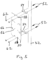
FIG. 5 is an exploded perspective view of an equipment stand according to the present invention.
FIG. 6 is an exploded perspective view of an equipment stand according to the present invention.
FIG. 7 is a perspective view of an exterior shell according to the present invention.
FIG. 8 is a cut-away perspective view of an exterior shell according to the present invention.
FIG. 9 is an exploded perspective view of an exterior shell according to the present invention.
DETAILED DESCRIPTION OF THE INVENTION
The present invention is a wireless bollard. The wireless bollard is an enclosure and mounting solution which is designed to secure and protect devices such as wireless equipment, Wi-Fi, telemetry, multi-media gateways, environmental monitoring, sensing devices, and their associated cables, connectors, power supplies media-converters etc. which may be mounted outside or in public venues. The wireless bollard provides for positioning enclosed electronic devices and antennas for optimum wireless coverage, while protecting the equipment from weather, tampering and abuse. The wireless bollard provides an enclosure with an exterior which is architecturally aesthetic, and also does not affect or impeded the wireless coverage. The wireless bollard provides for fast and easy installation and maintenance of the equipment.
The wireless bollard includes an exterior shell 10, equipment stand 12, anchor base 14, and an optional bolt cover 16. FIGS. 1-2 show different embodiments of the wireless bollard. Each embodiment includes the exterior shell 10, equipment stand 12, and anchor base 14. The difference between the embodiments of FIGS. 1-2 is the anchor base 14. The equipment stand 12 and exterior shell 10 are mounted to the anchor bases 14 shown in FIGS. 3-4. The anchor base 14 is a plate 18 that will be typically permanently attached to concrete, asphalt or flooring that is on a ground level surface. Anchors slots 20 as shown in FIGS. 1-4 are used to secure the anchor base 14 to the ground level surface, along with fasteners such as bolts or studs and nuts. The anchor base 14 may also be temporarily fixed to a softer ground level surface such as soil using ground anchors or spikes with the anchor slots. The anchor base 14 includes a plurality of sets of threaded pole base holes 22 to provide different locations to mount the equipment stand 12, so that the equipment stand 12 can be positioned as desired to point the devices in the proper direction. The anchor base 14 includes at least one conduit opening 24 for conduit, cabling and wires to enter the wireless bollard. The anchor base 14 includes shell mounting points for the exterior shell 10. FIGS. 1 and 3 show shell mounting tabs 25 that each has two threaded shell holes 26 to serve as the shell mounting points. FIGS. 2 and 4 show a mounting ring 28 having four threaded shell holes 26 to serve as the shell mounting points.
The equipment stand 12 is an interior structure for mounting and positioning the devices. The equipment stand 12 can accommodate access points with internal antennas, access points with attached dipole antennas, omnidirectional antennas, directional antennas and other equipment. The equipment stand 12 provides an adjustable platform which permits antennas to be positioned and directed for the desired coverage. Devices 30 are mounted on the adjustable equipment stand 12, with the antennas oriented in the desired direction or position. The devices 30 are connected to power and or data cable that come through the anchor base 14. The equipment stand 12 is shown to include a pole 32, pole base 34, and a device mounting assembly. The pole 32 is preferably of a non-metallic material, such as fiberglass. The pole base 34 includes a mounting flange 36 and a pole collar 38 extending up from the mounting flange 36. The mounting flange 36 includes anchor base holes 40 to accept fasteners 42. The pole base 34 mounts to one of the sets of pole base holes 22 of the anchor base 14 by aligning the anchor base holes 40 of the mounting flange 36 with the pole base holes 22 and using the fasteners 42 to secure the pole base 34 to the anchor base 14. The pole collar 38 includes a pole receiving recess 44 and collar set screws 46 that penetrate into the pole receiving recess 44. A bottom end 48 of the pole 32 slides into the pole receiving recess 44 and is secured in place using the collar set screws 46. The device mounting assembly is a pole mount bracket that has components that are used to mount the device 30 or devices 30 to the pole 32. FIGS. 1-2 and 5 show a version of the device mounting assembly that includes a device plate 50 and two pole clamp assemblies. The pole clamp assemblies each include a U bolt 52 and saddle clamp 54. The saddle clamp 54 includes a round side match the shape of the pole 32 and to go around the pole 32. The saddle clamp 54 includes a flat side to provide a mounting surface for the device plate 50. The device plate 50 includes device mount holes 56 and pole mount holes 58. The pole mount holes 58 are positioned to receive the ends of the U bolts 52 so that the device plate 50 rests against the flat side of the saddle clamp 54. Nuts 62 on the U bolts 52 secure the device plate 50 and the U bolts 52 to the pole 32 due to the clamping action of the saddle clamp 54. It may be desirable to mount some access points or antennas in a horizontal orientation, as shown in FIG. 6. FIG. 6 shows a device plate 64 with a mounting flange 66 so the device plate 64 can be mounted ninety degrees to the flat side of the saddle clamp 54 and the pole 32. FIG. 6 also shows a device interface plate 65 which mounts to the device plate 64 using fasteners and the device mount holes 56, where the device 30 mounts to the device interface plate 65. The use of device interface plates allow for the device plates to be universal and the device interface plate to be device specific. The device mounting assembly may articulate to mount access points in a horizontal or different orientation, or on top of the pole 32. There can be more than one device mounting assembly mounted to the pole 32 to allow for multiple devices 30 to be mounted to the pole 32, as shown in FIG. 2. The pole 32 and device mounting assembly allows for the orientation and direction of antennas properly without impeding the wireless signal. Most of the access points and antennas from different vendors are provided with components for outdoor pole mounting. The device 30 can be moved up and down the pole 32 to position access points and antennas where desired. The pole 32 can also be mounted in multiple positions on the anchor base 14, which is based on what set of pole base holes 22 are used. By positioning both the pole 32 and the orientation of the access point or antenna, the wireless designer can provide the coverage desired. Other items may be attached to the equipment stand 12 such as cables, power supplies, power outlets, media converters, switches, etc.
The exterior shell 10 fits over the equipment stand 12 and device 30 and is fastened to the anchor base 14, as shown in FIGS. 1 and 2. FIG. 1 shows anchor holes 68 near the bottom of the exterior shell 10 that are used to secure the exterior shell 10 to the anchor base 14 using threaded fasteners 70 with the threaded shell holes 26 of mounting tabs 25. FIG. 2 shows anchor holes 68 near the bottom of the exterior shell 10 that are used to secure the exterior shell 10 to the anchor base 14 using threaded fasteners 70 with the threaded shell holes 26 located on the mounting ring 28. The exterior shell 10 is shown as a round cylinder shape that has a height that is taller than its width and is typically referred to as a bollard. The cylinder shape can be other than round, such as square or hexagonal. The exterior shell 10 is of a material which is transparent to wireless signals and protects the electronic equipment within the exterior shell 10 from weather, spraying water, tampering, theft, and vandalism. The exterior shell 10 can be made of lightweight materials or heavy weight materials designed to take abuse during an act of vandalism. It is recommended that the exterior shell 10 be of a non-metallic material in order to have minimal impact on a wireless signal. The exterior shell 10 may be fiberglass or plastic material. Most importantly the exterior shell 10 provides for concealing all of the enclosed components. The exterior shell 10 may have a flat, beveled, domed, or pointed top, where FIGS. 1-2 show a beveled top 72 and FIGS. 7-8 show a domed top 74. FIG. 2 shows the bolt cover 16 that can be slid over the exterior shell 10 attached to cover tabs 76 to conceal the fasteners 70 which attach the exterior shell 10 to the anchor base 14. Screws 78 are shown fastening the bolt cover 16 to the cover tabs 76 of the anchor base 14, where the screws 78 and cover tabs 76 are a bolt cover fastening assembly to attach the bolt cover 16 to the wireless bollard. Non-screw fasteners can also be used to mount the bolt cover 16 to either the anchor base 14 or exterior shell 10. An example of non-screw fasteners are snap tabs and holes to receive the tabs that work together to form the bolt cover fastening assembly. The bolt cover 16 improves appearance and protects the bollard from lawn mowers, weed whackers, etc. FIGS. 7-8 show the exterior shell 10 with air vents 80 near the top of the exterior shell 10. The air vents 80 are slots in the near the top of the exterior shell 10 that allow heat generated by a device to dissipate. The exterior shell 10 may have openings in the exterior for different wired connections. For example, there may be external RJ-45, USB, HDMI, data, RF coaxial, antenna, power or other connectors. FIG. 9 shows an exterior shell 10 with an access panel 82 that can be opened to access the mounted device and wired connections.
While different embodiments of the invention have been described in detail herein, it will be appreciated by those skilled in the art that various modifications and alternatives to the embodiments could be developed in light of the overall teachings of the disclosure. Accordingly, the particular arrangements are illustrative only and are not limiting as to the scope of the invention that is to be given the full breadth of any and all equivalents thereof.

Claims (9)

We claim:
1. A wireless bollard adapted to house electrical and electronic devices, comprising:
an anchor base adapted to be attached to a ground level surface;
an equipment stand mounted within said wireless bollard, said equipment stand adapted to receive and support at least one device;
an exterior shell which fits over said equipment stand adapted to protect the device and allow transmission of wireless signals, said exterior shell mounted to said anchor base, said exterior shell having a shape that is taller than is wide; and
wherein said equipment stand includes a pole, pole base to support said pole with said wireless bollard and a device mounting assembly that mounts to said pole.
2. The wireless bollard of claim 1, wherein said pole base includes a mounting flange to mount said pole base to said anchor base and a pole collar extending up from said mounting flange, said pole collar including a pole receiving recess to receive an end of said pole.
3. The wireless bollard of claim 2, wherein said anchor base includes a plurality of sets of pole base holes to provide different locations to mount said equipment stand so that said equipment stand can be positioned as desired to point the devices in a proper direction; and wherein said mounting flange including anchor base holes aligned to match with one of said sets of pole base holes.
4. The wireless bollard of claim 1, wherein said device mounting assembly is a pole mount bracket that has components that are used to mount the device to the pole.
5. The wireless bollard of claim 1, wherein said pole mount bracket includes a device plate adapted to mount a device and two pole clamp assemblies, said pole clamp assemblies each including a U bolt, two nuts and a saddle clamp, said saddle clamp includes a round side to go around said pole and a flat side to provide a mounting surface for said device plate, said device plate includes pole mount holes to receive said U bolts.
6. The wireless bollard of claim 5, wherein said device plate is mounted to said flat side so said device plate is ninety degrees to said length of said pole.
7. A wireless bollard adapted to house electrical and electronic devices, comprising:
an anchor base adapted to be attached to a ground level surface;
an equipment stand mounted within said wireless bollard, said equipment stand adapted to receive and support at least one device;
an exterior shell which fits over said equipment stand adapted to protect the device and allow transmission of wireless signals, said exterior shell mounted to said anchor base, said exterior shell having a shape that is taller than is wide; and
a bolt cover to surround said exterior shell near said anchor base.
8. The wireless bollard of claim 7, wherein said equipment stand includes a pole, pole base to support said pole with said wireless bollard and a device mounting assembly that mounts to said pole.
9. A wireless bollard adapted to house electrical and electronic devices, comprising:
an anchor base adapted to be attached to a ground level surface;
an equipment stand mounted within said wireless bollard, said equipment stand adapted to receive and support at least one device;
an exterior shell which fits over said equipment stand adapted to protect the device and allow transmission of wireless signals, said exterior shell mounted to said anchor base, said exterior shell having a shape that is taller than is wide;
wherein said exterior shell has anchor holes, where said anchor base includes threaded mounting points and where said exterior shell is mounted to said anchor base using bolts, said anchor holes and said threaded mounting points; and
wherein said equipment stand includes a pole, pole base to support said pole with said wireless bollard and a device mounting assembly that mounts to said pole.
US16/006,916 2017-06-15 2018-06-13 Wireless bollard Active 2039-02-26 US10869401B1 (en)

Priority Applications (1)

Application Number Priority Date Filing Date Title
US16/006,916 US10869401B1 (en) 2017-06-15 2018-06-13 Wireless bollard

Applications Claiming Priority (2)

Application Number Priority Date Filing Date Title
US201762520030P 2017-06-15 2017-06-15
US16/006,916 US10869401B1 (en) 2017-06-15 2018-06-13 Wireless bollard

Publications (1)

Publication Number Publication Date
US10869401B1 true US10869401B1 (en) 2020-12-15

Family

ID=73746946

Family Applications (1)

Application Number Title Priority Date Filing Date
US16/006,916 Active 2039-02-26 US10869401B1 (en) 2017-06-15 2018-06-13 Wireless bollard

Country Status (1)

Country Link
US (1) US10869401B1 (en)

Cited By (4)

* Cited by examiner, † Cited by third party
Publication number Priority date Publication date Assignee Title
US20220166903A1 (en) * 2019-03-27 2022-05-26 Denis N. Savelyev Universal mounting case for video cameras
USD1004554S1 (en) * 2021-09-29 2023-11-14 Hubbell Incorporated Outdoor power post cover
USD1004552S1 (en) * 2021-09-29 2023-11-14 Hubbell Incorporated Outdoor power post cover
USD1013639S1 (en) * 2021-09-29 2024-02-06 Hubbell Incorporated Combined outdoor power post and outdoor power post cover

Citations (66)

* Cited by examiner, † Cited by third party
Publication number Priority date Publication date Assignee Title
US2808135A (en) * 1951-01-30 1957-10-01 Utility Pole Company Metal pole structure and method
US2916539A (en) * 1956-11-07 1959-12-08 Utility Products Co Above ground tap enclosure for subterranean cable
US2916591A (en) * 1956-11-19 1959-12-08 B & C Metal Stamping Company Electrical switch and pedestal housing structure
US3055970A (en) * 1958-03-03 1962-09-25 Handley Ind Inc Lead test box
US3153116A (en) * 1961-10-16 1964-10-13 Mc Graw Edison Co Fused banking pedestal with insulating terminal shield means
US3257496A (en) * 1964-01-06 1966-06-21 Douglas L P Hamilton Tap enclosure for use with underground utility cables
US3309456A (en) * 1964-07-14 1967-03-14 Clayton C Connell Above ground terminal tap enclosure for subterranean cables
US3373276A (en) * 1965-07-26 1968-03-12 Kenneth W. Klein Terminal pedestal for underground wiring systems
US3435124A (en) * 1966-02-07 1969-03-25 William H Channell Pedestal and underground terminals for buried cable systems
US3652779A (en) * 1971-04-21 1972-03-28 Kenneth D Grinols Underground cable pedestal
US3691288A (en) * 1970-12-14 1972-09-12 Zinsco Electrical Products Electrical power outlet for trailer camp sites and the like
US3714369A (en) * 1971-12-28 1973-01-30 Repco Products Corp Pedestal for electrical circuit components having a flexible protective dielectric shield
US3769460A (en) * 1972-03-09 1973-10-30 J Charles Mobile home telephone terminal system
US3812279A (en) * 1973-02-12 1974-05-21 H Voegeli Cable television housing with lockably joined cover and base
US3928712A (en) * 1974-04-05 1975-12-23 Hinman Specialties Inc Terminal enclosure with artificial foliage
US4015397A (en) * 1974-04-29 1977-04-05 Textron, Inc. Service poles and accessories
US4097683A (en) * 1976-09-15 1978-06-27 Coil Sales & Manufacturing Co. Terminal housing for buried electrical cables and method of expanding same
US4284300A (en) * 1979-08-13 1981-08-18 Metalfab Industries, Inc. Security locking assembly
US4365108A (en) * 1981-07-09 1982-12-21 Bright William L Secondary power pedestal for electrical equipment
US4382155A (en) * 1980-09-22 1983-05-03 Borin F W Lock for a test station apparatus
US4415217A (en) * 1981-07-16 1983-11-15 Raychem Corporation Cable joining connector and method
US4519657A (en) * 1980-02-19 1985-05-28 Common Sense Products Pty. Ltd. Multiple service unit
US4626616A (en) * 1984-12-12 1986-12-02 Masters Larry C Anti-tapping device to prevent unauthorized connections to electrical utility service cables
US4631353A (en) * 1984-10-31 1986-12-23 Reliance Electric Company Terminal pedestal for buried cable installation
US4751610A (en) * 1986-06-02 1988-06-14 Nickola Anne D Plural utility supply pedestal including contained common grounding means
US4873600A (en) * 1987-10-05 1989-10-10 Unicorn Electrical Products Utility pedestal
US4887187A (en) * 1986-06-02 1989-12-12 Nickola Anne D Plural utility supply pedestal including contained common grounding means
US4892978A (en) * 1989-03-06 1990-01-09 William Axworthy Self-supporting pedestal
US5184279A (en) * 1991-02-21 1993-02-02 General Electric Company Power pedestal having television, telephone and luminaire adapter unit
US5196988A (en) * 1991-02-21 1993-03-23 General Electric Company Power pedestal television and telephone adapter unit
US5210374A (en) * 1990-05-21 1993-05-11 Channell William H Terminal housing for buried communication lines
US5384427A (en) * 1991-09-20 1995-01-24 Reliance Comm/Tec Corporation Flood protection pedestal
USD354739S (en) * 1993-06-30 1995-01-24 Durham Rodney L Underground storage unit for items sensitive to environmental conditions
US5400212A (en) * 1994-03-23 1995-03-21 David J. Corby Preconstruction utility meter pedestal
US5401902A (en) * 1993-01-26 1995-03-28 Middlebrook; John S. Reentrable moisture barrier
USD367464S (en) * 1995-03-15 1996-02-27 Jones Karl M Utility module pedestal
US5611616A (en) * 1995-01-27 1997-03-18 Chandler Systems, Inc. Electrical controls enclosure
US5734776A (en) * 1996-08-28 1998-03-31 Adc Telecommunications, Inc. Outside plant cross-connect apparatus
US5860715A (en) * 1997-03-14 1999-01-19 The Toro Company Equipment enclosure
USD434001S (en) * 1999-08-09 2000-11-21 Sayger Jack M Utility box
US20010018978A1 (en) * 1996-09-16 2001-09-06 Gordin Myron K. Ballast box pole mounting system
US20020096346A1 (en) * 2001-01-22 2002-07-25 Marconi Communications, Inc. Vented cap for equipment pedestal
US6586671B1 (en) * 2002-08-06 2003-07-01 Interrail Signal, Inc. Above ground track signal terminal apparatus
US6877886B2 (en) * 2002-04-22 2005-04-12 Engineered Products Co. Landscape lightpost
US6975505B2 (en) * 2003-12-22 2005-12-13 General Electric Company Electrical service entrance with neutral
US20050285011A1 (en) * 2004-06-23 2005-12-29 Harwood Ronald P Support base for a structural pole
US7045710B1 (en) * 2005-08-31 2006-05-16 3M Innovative Properties Company Enclosure for telecommunication lines and splices
US20060254794A1 (en) * 2005-03-09 2006-11-16 Burke Edward J Enclosure system for underground utility connections
US20070182567A1 (en) * 2006-01-27 2007-08-09 Orbiter, Llc Portable lap counter and system
US7351909B1 (en) * 2004-06-10 2008-04-01 Charles Industries, Ltd. Multilayered housing for electronics enclosures
US7357009B2 (en) * 2003-11-13 2008-04-15 Emerson Network Power, Energy Systems, North America, Inc. Pedastal closure assembly having snag-free lock
US7361832B2 (en) * 2006-06-08 2008-04-22 Dively Robert C Outdoor electrical enclosure and hinge-less door assembly therefor
US20080253062A1 (en) * 2007-04-12 2008-10-16 Eaton Corporation Power pedestal and base assembly therefor
US20080253061A1 (en) * 2007-04-11 2008-10-16 Seff Paul D Vehicle or marina power pedestal including transient voltage surge suppression
US20090057119A1 (en) * 2007-09-04 2009-03-05 Burkett Karl A Break away base for electrical device
US20100051310A1 (en) * 2008-08-29 2010-03-04 Wurzer David T Power post
US20100052549A1 (en) * 2008-08-26 2010-03-04 Jamas Enterprises, LLC. Illuminated Bollard for Loading Dock
US7700874B2 (en) * 2007-08-24 2010-04-20 Emerson Network Power, Energy Systems, North America, Inc. Cable mounting structure and snap fit door hinge for telecommunications distribution pedestal
US8089747B2 (en) * 2009-05-22 2012-01-03 Eaton Corporation Power pedestal and system employing same
US20120256810A1 (en) * 2009-09-14 2012-10-11 Caldwell Steven R Methods of modifying erect concealed antenna towers and associated modified towers and devices therefor
US20120307069A1 (en) * 2011-06-02 2012-12-06 James Pierce Surveillance system with video compression for wireless transmission
US9382722B2 (en) * 2013-07-25 2016-07-05 Valmont West Coast Engineering Ltd. Anti-theft assembly for inhibiting theft of cable from light poles
US9768592B2 (en) * 2015-08-19 2017-09-19 Hubbell Incorporated Utility enclosure pedestal
US9991689B2 (en) * 2015-12-16 2018-06-05 Eaton Intelligent Power Limited Power pedestal and mounting assembly therefor
US10053861B2 (en) * 2015-03-05 2018-08-21 Western Timber Frame, Inc. Power distribution post for use in timber frame structures
US10158221B2 (en) * 2014-10-29 2018-12-18 Eaton Intelligent Power Limited Vehicle or marina power pedestal including ground fault indicator

Patent Citations (68)

* Cited by examiner, † Cited by third party
Publication number Priority date Publication date Assignee Title
US2808135A (en) * 1951-01-30 1957-10-01 Utility Pole Company Metal pole structure and method
US2916539A (en) * 1956-11-07 1959-12-08 Utility Products Co Above ground tap enclosure for subterranean cable
US2916591A (en) * 1956-11-19 1959-12-08 B & C Metal Stamping Company Electrical switch and pedestal housing structure
US3055970A (en) * 1958-03-03 1962-09-25 Handley Ind Inc Lead test box
US3153116A (en) * 1961-10-16 1964-10-13 Mc Graw Edison Co Fused banking pedestal with insulating terminal shield means
US3257496A (en) * 1964-01-06 1966-06-21 Douglas L P Hamilton Tap enclosure for use with underground utility cables
US3309456A (en) * 1964-07-14 1967-03-14 Clayton C Connell Above ground terminal tap enclosure for subterranean cables
US3373276A (en) * 1965-07-26 1968-03-12 Kenneth W. Klein Terminal pedestal for underground wiring systems
US3435124A (en) * 1966-02-07 1969-03-25 William H Channell Pedestal and underground terminals for buried cable systems
US3691288A (en) * 1970-12-14 1972-09-12 Zinsco Electrical Products Electrical power outlet for trailer camp sites and the like
US3652779A (en) * 1971-04-21 1972-03-28 Kenneth D Grinols Underground cable pedestal
US3714369A (en) * 1971-12-28 1973-01-30 Repco Products Corp Pedestal for electrical circuit components having a flexible protective dielectric shield
US3769460A (en) * 1972-03-09 1973-10-30 J Charles Mobile home telephone terminal system
US3812279A (en) * 1973-02-12 1974-05-21 H Voegeli Cable television housing with lockably joined cover and base
US3928712A (en) * 1974-04-05 1975-12-23 Hinman Specialties Inc Terminal enclosure with artificial foliage
US4015397A (en) * 1974-04-29 1977-04-05 Textron, Inc. Service poles and accessories
US4097683A (en) * 1976-09-15 1978-06-27 Coil Sales & Manufacturing Co. Terminal housing for buried electrical cables and method of expanding same
US4284300A (en) * 1979-08-13 1981-08-18 Metalfab Industries, Inc. Security locking assembly
US4519657A (en) * 1980-02-19 1985-05-28 Common Sense Products Pty. Ltd. Multiple service unit
US4382155A (en) * 1980-09-22 1983-05-03 Borin F W Lock for a test station apparatus
US4365108A (en) * 1981-07-09 1982-12-21 Bright William L Secondary power pedestal for electrical equipment
US4415217A (en) * 1981-07-16 1983-11-15 Raychem Corporation Cable joining connector and method
US4631353A (en) * 1984-10-31 1986-12-23 Reliance Electric Company Terminal pedestal for buried cable installation
US4626616A (en) * 1984-12-12 1986-12-02 Masters Larry C Anti-tapping device to prevent unauthorized connections to electrical utility service cables
US4887187A (en) * 1986-06-02 1989-12-12 Nickola Anne D Plural utility supply pedestal including contained common grounding means
US4751610A (en) * 1986-06-02 1988-06-14 Nickola Anne D Plural utility supply pedestal including contained common grounding means
US4873600A (en) * 1987-10-05 1989-10-10 Unicorn Electrical Products Utility pedestal
US4892978A (en) * 1989-03-06 1990-01-09 William Axworthy Self-supporting pedestal
US5210374A (en) * 1990-05-21 1993-05-11 Channell William H Terminal housing for buried communication lines
US5184279A (en) * 1991-02-21 1993-02-02 General Electric Company Power pedestal having television, telephone and luminaire adapter unit
US5196988A (en) * 1991-02-21 1993-03-23 General Electric Company Power pedestal television and telephone adapter unit
US5384427A (en) * 1991-09-20 1995-01-24 Reliance Comm/Tec Corporation Flood protection pedestal
US5401902A (en) * 1993-01-26 1995-03-28 Middlebrook; John S. Reentrable moisture barrier
USD354739S (en) * 1993-06-30 1995-01-24 Durham Rodney L Underground storage unit for items sensitive to environmental conditions
US5400212A (en) * 1994-03-23 1995-03-21 David J. Corby Preconstruction utility meter pedestal
US5611616A (en) * 1995-01-27 1997-03-18 Chandler Systems, Inc. Electrical controls enclosure
USD367464S (en) * 1995-03-15 1996-02-27 Jones Karl M Utility module pedestal
US5734776A (en) * 1996-08-28 1998-03-31 Adc Telecommunications, Inc. Outside plant cross-connect apparatus
US20010018978A1 (en) * 1996-09-16 2001-09-06 Gordin Myron K. Ballast box pole mounting system
US5860715A (en) * 1997-03-14 1999-01-19 The Toro Company Equipment enclosure
USD434001S (en) * 1999-08-09 2000-11-21 Sayger Jack M Utility box
US20020096346A1 (en) * 2001-01-22 2002-07-25 Marconi Communications, Inc. Vented cap for equipment pedestal
US6501015B2 (en) * 2001-01-22 2002-12-31 Marconi Communications, Inc. Vented cap for equipment pedestal
US6877886B2 (en) * 2002-04-22 2005-04-12 Engineered Products Co. Landscape lightpost
US6586671B1 (en) * 2002-08-06 2003-07-01 Interrail Signal, Inc. Above ground track signal terminal apparatus
US7357009B2 (en) * 2003-11-13 2008-04-15 Emerson Network Power, Energy Systems, North America, Inc. Pedastal closure assembly having snag-free lock
US6975505B2 (en) * 2003-12-22 2005-12-13 General Electric Company Electrical service entrance with neutral
US7351909B1 (en) * 2004-06-10 2008-04-01 Charles Industries, Ltd. Multilayered housing for electronics enclosures
US20050285011A1 (en) * 2004-06-23 2005-12-29 Harwood Ronald P Support base for a structural pole
US20060254794A1 (en) * 2005-03-09 2006-11-16 Burke Edward J Enclosure system for underground utility connections
US7045710B1 (en) * 2005-08-31 2006-05-16 3M Innovative Properties Company Enclosure for telecommunication lines and splices
US20070182567A1 (en) * 2006-01-27 2007-08-09 Orbiter, Llc Portable lap counter and system
US7361832B2 (en) * 2006-06-08 2008-04-22 Dively Robert C Outdoor electrical enclosure and hinge-less door assembly therefor
US20080253061A1 (en) * 2007-04-11 2008-10-16 Seff Paul D Vehicle or marina power pedestal including transient voltage surge suppression
US20080253062A1 (en) * 2007-04-12 2008-10-16 Eaton Corporation Power pedestal and base assembly therefor
US7700874B2 (en) * 2007-08-24 2010-04-20 Emerson Network Power, Energy Systems, North America, Inc. Cable mounting structure and snap fit door hinge for telecommunications distribution pedestal
US20090057119A1 (en) * 2007-09-04 2009-03-05 Burkett Karl A Break away base for electrical device
US20100052549A1 (en) * 2008-08-26 2010-03-04 Jamas Enterprises, LLC. Illuminated Bollard for Loading Dock
US20100051310A1 (en) * 2008-08-29 2010-03-04 Wurzer David T Power post
US7807924B2 (en) * 2008-08-29 2010-10-05 Wurzer David T Power post
US8089747B2 (en) * 2009-05-22 2012-01-03 Eaton Corporation Power pedestal and system employing same
US20120256810A1 (en) * 2009-09-14 2012-10-11 Caldwell Steven R Methods of modifying erect concealed antenna towers and associated modified towers and devices therefor
US20120307069A1 (en) * 2011-06-02 2012-12-06 James Pierce Surveillance system with video compression for wireless transmission
US9382722B2 (en) * 2013-07-25 2016-07-05 Valmont West Coast Engineering Ltd. Anti-theft assembly for inhibiting theft of cable from light poles
US10158221B2 (en) * 2014-10-29 2018-12-18 Eaton Intelligent Power Limited Vehicle or marina power pedestal including ground fault indicator
US10053861B2 (en) * 2015-03-05 2018-08-21 Western Timber Frame, Inc. Power distribution post for use in timber frame structures
US9768592B2 (en) * 2015-08-19 2017-09-19 Hubbell Incorporated Utility enclosure pedestal
US9991689B2 (en) * 2015-12-16 2018-06-05 Eaton Intelligent Power Limited Power pedestal and mounting assembly therefor

Cited By (4)

* Cited by examiner, † Cited by third party
Publication number Priority date Publication date Assignee Title
US20220166903A1 (en) * 2019-03-27 2022-05-26 Denis N. Savelyev Universal mounting case for video cameras
USD1004554S1 (en) * 2021-09-29 2023-11-14 Hubbell Incorporated Outdoor power post cover
USD1004552S1 (en) * 2021-09-29 2023-11-14 Hubbell Incorporated Outdoor power post cover
USD1013639S1 (en) * 2021-09-29 2024-02-06 Hubbell Incorporated Combined outdoor power post and outdoor power post cover

Similar Documents

Publication Publication Date Title
US10869401B1 (en) Wireless bollard
US9837698B2 (en) Small cell communications pole, system, and method
US8743013B2 (en) System and method for payload enclosure
EP3710653B1 (en) Lamp post with a functional pole module with bracket
US10224594B2 (en) Radio and power pole
US10505271B2 (en) Small cell pole antenna configuration
CN111279119A (en) Lamppost with improved cooling effect
US10854948B2 (en) Handrail mountable wireless components installation apparatus and method
EP3914855A1 (en) Lamp post with tubular pole
US10851936B1 (en) Camera mount plate and module access slide for poles used for roadside electronic systems
WO2004095386A1 (en) Surveillance apparatus, system and method
US20130113680A1 (en) Antenna concealment structures incorporating fabric concealment shells
US20110052179A1 (en) Mounting device for security camera
US9546755B2 (en) Accessory mounting system
AU2012101222A4 (en) Radio Frequency Identification (RFID) beacon including controllable signal direction and range
US9001211B1 (en) Surveillance system apparatus
US20050250545A1 (en) Modular connection system
US7039366B1 (en) Antenna and access point mounting system and method
US7946864B1 (en) Retractable outdoor electrical power receptacle
CN215644959U (en) Street lamp type antenna device
GB2579888A (en) Floor panel
CN218917681U (en) Outdoor weather station
RU203562U1 (en) Universal junction box
AU2020100818A4 (en) Camera Support
GB2460639A (en) Closed circuit television surveillance unit having an air conditioning unit

Legal Events

Date Code Title Description
FEPP Fee payment procedure

Free format text: ENTITY STATUS SET TO UNDISCOUNTED (ORIGINAL EVENT CODE: BIG.); ENTITY STATUS OF PATENT OWNER: LARGE ENTITY

Free format text: ENTITY STATUS SET TO UNDISCOUNTED (ORIGINAL EVENT CODE: BIG.); ENTITY STATUS OF PATENT OWNER: SMALL ENTITY

FEPP Fee payment procedure

Free format text: ENTITY STATUS SET TO SMALL (ORIGINAL EVENT CODE: SMAL); ENTITY STATUS OF PATENT OWNER: LARGE ENTITY

Free format text: ENTITY STATUS SET TO SMALL (ORIGINAL EVENT CODE: SMAL); ENTITY STATUS OF PATENT OWNER: SMALL ENTITY

STCF Information on status: patent grant

Free format text: PATENTED CASE

FEPP Fee payment procedure

Free format text: ENTITY STATUS SET TO UNDISCOUNTED (ORIGINAL EVENT CODE: BIG.); ENTITY STATUS OF PATENT OWNER: LARGE ENTITY

FEPP Fee payment procedure

Free format text: PETITION RELATED TO MAINTENANCE FEES GRANTED (ORIGINAL EVENT CODE: PTGR); ENTITY STATUS OF PATENT OWNER: LARGE ENTITY

MAFP Maintenance fee payment

Free format text: PAYMENT OF MAINTENANCE FEE, 4TH YEAR, LARGE ENTITY (ORIGINAL EVENT CODE: M1551); ENTITY STATUS OF PATENT OWNER: LARGE ENTITY

Year of fee payment: 4