US10869225B2 - Automatically select uplink based on user anchor controller - Google Patents
Automatically select uplink based on user anchor controller Download PDFInfo
- Publication number
- US10869225B2 US10869225B2 US15/992,583 US201815992583A US10869225B2 US 10869225 B2 US10869225 B2 US 10869225B2 US 201815992583 A US201815992583 A US 201815992583A US 10869225 B2 US10869225 B2 US 10869225B2
- Authority
- US
- United States
- Prior art keywords
- user
- controller
- access point
- processor
- network
- Prior art date
- Legal status (The legal status is an assumption and is not a legal conclusion. Google has not performed a legal analysis and makes no representation as to the accuracy of the status listed.)
- Active
Links
Images


Classifications
-
- H—ELECTRICITY
- H04—ELECTRIC COMMUNICATION TECHNIQUE
- H04W—WIRELESS COMMUNICATION NETWORKS
- H04W28/00—Network traffic management; Network resource management
- H04W28/02—Traffic management, e.g. flow control or congestion control
- H04W28/08—Load balancing or load distribution
- H04W28/088—Load balancing or load distribution among core entities
-
- H—ELECTRICITY
- H04—ELECTRIC COMMUNICATION TECHNIQUE
- H04W—WIRELESS COMMUNICATION NETWORKS
- H04W28/00—Network traffic management; Network resource management
- H04W28/02—Traffic management, e.g. flow control or congestion control
- H04W28/08—Load balancing or load distribution
-
- H—ELECTRICITY
- H04—ELECTRIC COMMUNICATION TECHNIQUE
- H04L—TRANSMISSION OF DIGITAL INFORMATION, e.g. TELEGRAPHIC COMMUNICATION
- H04L5/00—Arrangements affording multiple use of the transmission path
- H04L5/003—Arrangements for allocating sub-channels of the transmission path
- H04L5/0044—Arrangements for allocating sub-channels of the transmission path allocation of payload
-
- H—ELECTRICITY
- H04—ELECTRIC COMMUNICATION TECHNIQUE
- H04L—TRANSMISSION OF DIGITAL INFORMATION, e.g. TELEGRAPHIC COMMUNICATION
- H04L5/00—Arrangements affording multiple use of the transmission path
- H04L5/003—Arrangements for allocating sub-channels of the transmission path
- H04L5/0058—Allocation criteria
- H04L5/0062—Avoidance of ingress interference, e.g. ham radio channels
-
- H—ELECTRICITY
- H04—ELECTRIC COMMUNICATION TECHNIQUE
- H04L—TRANSMISSION OF DIGITAL INFORMATION, e.g. TELEGRAPHIC COMMUNICATION
- H04L5/00—Arrangements affording multiple use of the transmission path
- H04L5/003—Arrangements for allocating sub-channels of the transmission path
- H04L5/0058—Allocation criteria
- H04L5/0064—Rate requirement of the data, e.g. scalable bandwidth, data priority
-
- H—ELECTRICITY
- H04—ELECTRIC COMMUNICATION TECHNIQUE
- H04L—TRANSMISSION OF DIGITAL INFORMATION, e.g. TELEGRAPHIC COMMUNICATION
- H04L61/00—Network arrangements, protocols or services for addressing or naming
- H04L61/50—Address allocation
- H04L61/5007—Internet protocol [IP] addresses
-
- H—ELECTRICITY
- H04—ELECTRIC COMMUNICATION TECHNIQUE
- H04W—WIRELESS COMMUNICATION NETWORKS
- H04W28/00—Network traffic management; Network resource management
- H04W28/02—Traffic management, e.g. flow control or congestion control
- H04W28/06—Optimizing the usage of the radio link, e.g. header compression, information sizing, discarding information
-
- H—ELECTRICITY
- H04—ELECTRIC COMMUNICATION TECHNIQUE
- H04W—WIRELESS COMMUNICATION NETWORKS
- H04W72/00—Local resource management
- H04W72/04—Wireless resource allocation
- H04W72/044—Wireless resource allocation based on the type of the allocated resource
-
- H04W72/0486—
-
- H04W72/10—
-
- H—ELECTRICITY
- H04—ELECTRIC COMMUNICATION TECHNIQUE
- H04W—WIRELESS COMMUNICATION NETWORKS
- H04W72/00—Local resource management
- H04W72/50—Allocation or scheduling criteria for wireless resources
- H04W72/52—Allocation or scheduling criteria for wireless resources based on load
-
- H—ELECTRICITY
- H04—ELECTRIC COMMUNICATION TECHNIQUE
- H04W—WIRELESS COMMUNICATION NETWORKS
- H04W72/00—Local resource management
- H04W72/50—Allocation or scheduling criteria for wireless resources
- H04W72/56—Allocation or scheduling criteria for wireless resources based on priority criteria
-
- H—ELECTRICITY
- H04—ELECTRIC COMMUNICATION TECHNIQUE
- H04W—WIRELESS COMMUNICATION NETWORKS
- H04W84/00—Network topologies
- H04W84/02—Hierarchically pre-organised networks, e.g. paging networks, cellular networks, WLAN [Wireless Local Area Network] or WLL [Wireless Local Loop]
- H04W84/10—Small scale networks; Flat hierarchical networks
- H04W84/12—WLAN [Wireless Local Area Networks]
-
- H—ELECTRICITY
- H04—ELECTRIC COMMUNICATION TECHNIQUE
- H04W—WIRELESS COMMUNICATION NETWORKS
- H04W92/00—Interfaces specially adapted for wireless communication networks
- H04W92/04—Interfaces between hierarchically different network devices
- H04W92/12—Interfaces between hierarchically different network devices between access points and access point controllers
Definitions
- access points use multiple uplink interfaces for link aggregation (LAG).
- LAG link aggregation
- the uplink selection in LAG is based on wireless band A (5 GHz) or G (2.4 Hz) to balance the traffic while ensuring the correct sequence of delivered packets.
- FIG. 1 is a block diagram illustrating an example WLAN including a wireless device capable of automatically select uplink based on user anchor controller (UAC) according to the present disclosure
- FIG. 2 is a block diagram illustrating an example WLAN including a wireless device capable of automatically select uplink based on UAC according to the present disclosure
- FIG. 3 is a block diagram illustrating an example WLAN including a wireless device capable of automatically select uplink based on UAC according to the present disclosure
- FIG. 4 is a block diagram illustrating an example WLAN including a wireless device capable of automatically select uplink based on UAC according to the present disclosure
- FIG. 5 is a flow chart illustrating an example method for automatically selecting uplink based on UAC according to present disclosure
- FIG. 6 is a flow chart illustrating an example method for automatically selecting uplink based on UAC according to present disclosure
- FIG. 7 is a block diagram illustrating example components for implementing the device shown in FIG. 1 according to present disclosure.
- FIG. 8 is a block diagram illustrating example components for implementing the device shown in FIG. 1 according to present disclosure.
- LAG uplink selection calculation is based on the characteristics in layer 2 and/or layer 3 headers of the network packets. This may be applicable to clear packets using the local forwarding mode because the characteristics in layer 2 and/or layer 3 header can be obtained directly from the clear packets.
- the AP may spread the packets based on the wireless band on which the packets are received. For example, packets from band A and band G may be sent to different uplink interfaces. Therefore, the uplink selection in LAG may be based on the wireless band (e.g., band A or band G) that the packet is received from.
- the wireless band e.g., band A or band G
- IP addresses are configured for and used by one AP at the same time.
- One IP address is used for packet transmission on wireless band A and the other IP is used for packet transmission on wireless band G.
- an AP may spread the packets based on the inner destination MAC address in transmit direction and do packet re-ordering in receive direction.
- the AP may still need to be configured with two IP addresses, and the packets may also need to be reordered.
- each network controller may be configured with a user anchor controller (UAC). That is to say, each UAC corresponds to a network controller.
- N UACs may be configured accordingly for the N network controllers.
- the UAC is a network device that is configured between an AP and a network controller.
- One AP can connect to multiple UACs, but one UAC connects to one AP and one network controller.
- Users of the AP can be assigned to the UAC, and the UAC can be assigned to an uplink interface of the AP. Therefore, it is possible to automatically select an uplink for each user based on the users corresponding UAC to transmit the user's data traffic.
- each user of the AP may be assigned to one of the UACs. Then, for each user of the AP, an uplink may be automatically selected based on the user's corresponding UAC to transmit the user's data traffic. That is to say, the uplink may be selected based on the UAC instead of checking the wireless band or target MAC address for LAC uplink selection.
- each network controller connected with the AP is configured with one UAC, and each user of the AP is assigned to one of the UACs, the user's data traffic is transmitted to the corresponding UAC. Further, each UAC may be assigned to an uplink interface of the AP. So, in both upstream and downstream packet transmissions, the UAC is the controller that is responsible for forwarding data traffic associated with a corresponding user(s).
- each network controller may configure a single IP address for the AP instead of two IP addresses. No additional IP address is configured, and the IP resource is saved.
- the network controller may use half of the tunnel resources to transmit the user's data traffic.
- the UAC can preserve the order of packet delivery for a specific user, thus eliminating the effort of packet re-ordering. Therefore, while improving the AP's usage efficiency of multiple uplink interfaces in the case of multiple network controllers, it also saves the IP address resources used by the network controller.
- a device may configure a UAC for each network controller when an AP is connected to at least two network controllers.
- the device can also assign each user of the AP to one of the UACs, and automatically select an uplink for each user based on the user's corresponding UAC to transmit the user's data traffic. Further, the device can assign each UAC to an uplink interface of the AP before selecting the uplink.
- a method comprising configuring, by a processor of an AP, a UAC for each network controller when the AP is connected to at least two network controllers; assigning, by the processor, each user of the AP to one of the UACs; and automatically selecting, by the processor, an uplink for each user based on the user's corresponding UAC to transmit the user's data traffic.
- a non-transitory computer readable storage medium storing instructions that, when executed by a processor of an AP, causes the processor to configure a UAC for each network controller when an AP is connected to at least two network controllers, to assign each user of the AP to one of the UACs, and to automatically select an uplink for each user based on the user's corresponding UAC to transmit the user's data traffic.
- a “network device” generally includes a device that is adapted to transmit and/or receive signaling and to process information within such signaling such as a station (e.g., any data processing equipment such as a computer, cellular phone, personal digital assistant, tablet devices, etc.), an access point, data transfer devices (such as network switches, routers, controllers, etc.) or the like.
- a station e.g., any data processing equipment such as a computer, cellular phone, personal digital assistant, tablet devices, etc.
- an access point data transfer devices (such as network switches, routers, controllers, etc.) or the like.
- an “access point” generally refers to receiving points for any known or convenient wireless access technology which may later become known. Specifically, the term AP is not intended to be limited to IEEE 802.11-based APs.
- APs generally function as an electronic device that is adapted to allow wireless devices to connect to a wired network via various communications standards.
- examples described herein below may include various components and features. Some of the components and features may be removed and/or modified without departing from a scope of the device, method and non-transitory computer readable storage medium for automatically select uplink based on UAC.
- an example or similar language means that a particular feature, structure, or characteristic described in connection with the example is included in at least one example, but not necessarily in other examples.
- the various instances of the phrase “in one example” or similar phrases in various places in the specification are not necessarily all referring to the same example.
- a component is a combination of hardware and software executing on that hardware to provide a given functionality.
- FIG. 1 is a block diagram illustrating an example WLAN including a wireless device capable of automatically select uplink based on UAC according to the present disclosure.
- a WLAN may include an AP 10 , at least two UACs 20 - 1 to 20 -N and at least two network controllers 30 - 1 to 30 -N, where each network controller may uniquely correspond to one UAC.
- the AP 10 may be connected to N network controllers 30 - 1 , . . . , 30 -N, so N UACs 20 - 1 , . . . , 20 -N may be set corresponding to the N network controllers 30 - 1 , . . . , 30 -N.
- the AP 10 may have two uplink interfaces, e.g. enet 0 and enet 1 as shown in FIG. 1 . Then, before selecting the uplink for each user, each UAC may be assigned to an uplink interface of the AP 10 . For example, as shown in FIG. 1 , the UAC 20 - 1 is assigned to the uplink interface enet 0 of the AP 10 , and the UAC 20 -N is assigned to the uplink interface enet 1 of the AP 10 .
- the AP 10 includes a processor 11 .
- the processor 11 may configure N UACs corresponding to the N network controllers, and each UAC may correspond uniquely to one network controller.
- the processor 11 may assign each user of the AP 10 to one of the N UACs. For example, the processor 11 may evenly assign all its users to N UACs. For another example, the processor 11 may assign all users to N UACs according to the load of each UAC. For another example, the processor 11 may assign all users to N UACs based on the priority or role of each user.
- the processor 11 may automatically select an uplink for each user based on the user's corresponding UAC to transmit the user's data traffic.
- the processor 11 may assign each UAC to an uplink interface of the AP 10 .
- the processor 11 may evenly assign all UACs to two uplink interfaces of the AP 10 .
- the processor 11 may assign all UACs to two uplink interfaces of the AP 10 according to the load of each uplink interface.
- the processor 11 may assign all UACs to two uplink interfaces of the AP 10 based on the priority of each UAC.
- the priority of each UAC can be predetermined, e.g., the priority of the first UAC can be predetermined to have the highest priority, the priority of the second UAC can be predetermined to have the second priority, . . . , and so on. Therefore, the UAC with the highest priority can be assigned to the uplink interface enet 0 and the UAC without the highest priority can be assigned to the uplink interface enet 1 , or vice versa.
- FIG. 2 is a block diagram illustrating an example WLAN including a wireless device capable of automatically select uplink based on UAC according to the present disclosure.
- a WLAN may include an AP 10 , two UACs (i.e. 20 - 1 and 20 - 2 ) and two network controllers (i.e. 30 - 1 and 30 - 2 ).
- the AP 10 may be connected to two network controllers 30 - 1 and 30 - 2 .
- the AP 10 includes a processor 11 , the processor 11 may configure two UACs (e.g., 20 - 1 and 20 - 2 ) corresponding to the two network controllers (e.g., 30 - 1 and 30 - 2 ), and each UAC may correspond uniquely to one network controller.
- the processor 11 may configure two UACs (e.g., 20 - 1 and 20 - 2 ) corresponding to the two network controllers (e.g., 30 - 1 and 30 - 2 ), and each UAC may correspond uniquely to one network controller.
- the processor 11 may assign each user of the AP 10 to one of the UACs. For example, the processor 11 may evenly assign all its users to two UACs (such as, when the AP 10 has 2*M users, the processor 11 may assign the first M users to UAC 20 - 1 , and assign the last M users to UAC 20 - 2 , or vice versa). For another example, the processor 11 may assign all users to two UACs according to the load of each UAC. For another example, the processor 11 may assign all users to two UACs based on the priority or role of each user.
- the processor 11 may automatically select an uplink for each user based on the user's corresponding UAC to transmit the user's data traffic.
- the AP 10 may have two uplink interfaces, e.g. enet 0 and enet 1 as shown in FIG. 2 . So, the processor 11 may assign each UAC to an uplink interface of the AP 10 .
- the processor 11 may evenly assign all UACs to two uplink interfaces of the AP 10 , such as, as shown in FIG. 2 , the UAC 20 - 1 is assigned to the uplink interface enet 0 of the AP 10 , and the UAC 20 - 2 is assigned to the uplink interface enet 1 of the AP 10 , or vice versa.
- the processor 11 may assign all UACs to two uplink interfaces of the AP 10 according to the load of each uplink interface.
- all UACs may be dynamically assigned to two uplink interfaces of the AP 10 . For instance, at one point of time, when the uplink interface enet 0 has a low load, the enet 0 may be the uplink interface transmitting user data traffic to two UACs (e.g., 20 - 1 , 20 - 2 ); and at a future point of time, when the enet 0 has a high load, the same enet 0 may transmit user data traffic to a single UAC (e.g., 20 - 1 ).
- the processor 11 may assign all UACs to two uplink interfaces of the AP 10 based on the priority of each UAC.
- the priority of each UAC can be predetermined, e.g., the priority of the UAC 20 - 1 can be predetermined to have the highest priority, the priority of the UAC 20 - 2 can be predetermined to have the second priority, or vice versa. Therefore, such as, as shown in FIG. 2 , the UAC 20 - 1 can be assigned to the uplink interface enet 0 of the AP 10 , and the UAC 20 - 2 can be assigned to the uplink interface enet 1 of the AP 10 , or vice versa.
- FIG. 3 is a block diagram illustrating an example WLAN including a wireless device capable of automatically select uplink based on UAC according to the present disclosure.
- a WLAN may include an AP 10 , three UACs (i.e. 20 - 1 , 20 - 2 and 20 - 3 ) and three network controllers (i.e. 30 - 1 , 30 - 2 and 30 - 3 ).
- the AP 10 may be connected to three network controllers 30 - 1 , 30 - 2 and 30 - 3 .
- the AP 10 includes a processor 11 , the processor 11 may configure three UACs (i.e. 20 - 1 , 20 - 2 and 20 - 3 ) corresponding to the three network controllers (i.e. 30 - 1 , 30 - 2 and 30 - 3 ), and each UAC may correspond uniquely to one network controller.
- the processor 11 may configure three UACs (i.e. 20 - 1 , 20 - 2 and 20 - 3 ) corresponding to the three network controllers (i.e. 30 - 1 , 30 - 2 and 30 - 3 ), and each UAC may correspond uniquely to one network controller.
- the processor 11 may assign each user of the AP 10 to one of the UACs. For example, the processor 11 may evenly assign all its users to three UACs (such as, when the AP 10 has 3*M users, the processor 11 may assign the first M users to UAC 20 - 1 , assign the second M users to UAC 20 - 2 , and assign the last M users to UAC 20 - 3 ). For another example, the processor 11 may assign all users to three UACs according to the load of each UAC. For another example, the processor 11 may assign all users to three UACs based on the priority of each user.
- the processor 11 may automatically select an uplink for each user based on the user's corresponding UAC to transmit the user's data traffic.
- the AP 10 may have two uplink interfaces, e.g. enet 0 and enet 1 as shown in FIG. 3 . So, the processor 11 may assign each UAC to an uplink interface of the AP 10 .
- the processor 11 may evenly assign all UACs to two uplink interfaces of the AP 10 , such as, as shown in FIG. 3 , the UAC 20 - 1 is assigned to the uplink interface enet 0 of the AP 10 , the UAC 20 - 2 and UAC 20 - 3 are assigned to the uplink interface enet 1 of the AP 10 .
- the processor 11 may assign all UACs to two uplink interfaces of the AP 10 according to the load of each uplink interface.
- all UACs may be dynamically assigned to two uplink interfaces of the AP 10 . For instance, at one point of time, when the uplink interface enet 0 has a low load, the enet 0 may be the uplink interface transmitting user data traffic to two UACs (e.g., 20 - 1 , 20 - 2 ); and at a future point of time, when the enet 0 has a high load, the same enet 0 may transmit user data traffic to a single UAC (e.g., 20 - 1 ).
- the processor 11 may assign all UACs to two uplink interfaces of the AP 10 based on the priority of each UAC.
- the priority of each UAC can be predetermined, e.g., the priority of the UAC 20 - 1 can be predetermined to have the highest priority, the priority of the UAC 20 - 2 and UAC 20 - 3 can be predetermined to have the second priority, or vice versa. Therefore, such as, as shown in FIG. 3 , the UAC 20 - 1 can be assigned to the uplink interface enet 0 of the AP 10 , and the UAC 20 - 2 and UAC 20 - 3 can be assigned to the uplink interface enet 1 of the AP 10 , or vice versa.
- FIG. 4 is a block diagram illustrating an example WLAN including a wireless device capable of automatically select uplink based on UAC according to the present disclosure.
- a WLAN may include an AP 10 , four UACs (i.e. 20 - 1 , 20 - 2 , 20 - 3 and 20 - 4 ) and four network controllers (i.e. 30 - 1 , 30 - 2 , 30 - 3 and 30 - 4 ).
- the AP 10 may be connected to four network controllers 30 - 1 , 30 - 2 , 30 - 3 and 30 - 4 .
- the AP 10 includes a processor 11 , the processor 11 may configure four UACs (i.e. 20 - 1 , 20 - 2 , 20 - 3 and 20 - 4 ) corresponding to the four network controllers (i.e. 30 - 1 , 30 - 2 , 30 - 3 and 30 - 4 ), and each UAC may correspond uniquely to one network controller.
- the processor 11 may configure four UACs (i.e. 20 - 1 , 20 - 2 , 20 - 3 and 20 - 4 ) corresponding to the four network controllers (i.e. 30 - 1 , 30 - 2 , 30 - 3 and 30 - 4 ), and each UAC may correspond uniquely to one network controller.
- the processor 11 may assign each user of the AP 10 to one of the UACs. For example, the processor 11 may evenly assign all its users to four UACs (such as, when the AP 10 has 4*M users, the processor 11 may assign the first M users to UAC 20 - 1 , assign the second M users to UAC 20 - 2 , assign the third M users to UAC 20 - 3 , and assign the last M users to UAC 20 - 4 ). For another example, the processor 11 may assign all users to four UACs according to the load of each UAC. For another example, the processor 11 may assign all users to four UACs based on the priority of each user.
- the processor 11 may evenly assign all its users to four UACs (such as, when the AP 10 has 4*M users, the processor 11 may assign the first M users to UAC 20 - 1 , assign the second M users to UAC 20 - 2 , assign the third M users to UAC 20 - 3 , and assign the last M users to UAC 20 - 4
- the processor 11 may automatically select an uplink for each user based on the user's corresponding UAC to transmit the user's data traffic.
- the AP 10 may have two uplink interfaces, e.g. enet 0 and enet 1 as shown in FIG. 4 . So, the processor 11 may assign each UAC to an uplink interface of the AP 10 .
- the processor 11 may evenly assign all UACs to two uplink interfaces of the AP 10 , such as, as shown in FIG. 4 , the UAC 20 - 1 and UAC 20 - 3 are assigned to the uplink interface enet 0 of the AP 10 , the UAC 20 - 2 and UAC 20 - 4 are assigned to the uplink interface enet 1 of the AP 10 .
- the processor 11 may assign all UACs to two uplink interfaces of the AP 10 according to the load of each uplink interface.
- the processor 11 may assign all UACs to two uplink interfaces of the AP 10 based on the priority of each UAC.
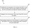
- FIG. 5 is a flow chart illustrating an example method for automatically selecting uplink based on UAC according to present disclosure.
- a method 500 comprises: configuring, by a processor of an AP, a UAC for each network controller when the AP is connected to at least two network controllers, at 501 .
- the AP may be connected to N network controllers.
- the processor of the AP may configure N UACs corresponding to the N network controllers, and each UAC may correspond uniquely to one network controller.
- the method 500 further comprises assigning, by the processor, each user of the AP to one of the UACs, at 502 .
- the processor may evenly assign all its users to UACs.
- the processor may assign all users to UACs according to the load of each UAC.
- the processor may assign all users to UACs based on the priority of each user.
- the method 500 also comprises automatically selecting, by the processor, an uplink for each user based on the user's corresponding UAC to transmit the user's data traffic, at 503 .
- FIG. 6 is a flow chart illustrating an example method for automatically select uplink based on UAC according to present disclosure.
- a method 600 comprises: configuring, by a processor of an AP, a UAC for each network controller when the AP is connected to at least two network controllers, at 601 .
- the AP may be connected to N network controllers.
- the processor of the AP may configure N UACs corresponding to the N network controllers, and each UAC may correspond uniquely to one network controller.
- the method 600 comprises assigning, by the processor, each user of the AP to one of the UACs, at 602 .
- the processor may evenly assign all its users to UACs.
- the processor may assign all users to UACs according to the load of each UAC.
- the processor may assign all users to UACs based on the priority of each user.
- the method 600 comprises assigning, by the processor, each UAC to an uplink interface of the AP, at 603 .
- the processor may evenly assign all UACs to uplink interfaces of the AP.
- the processor may assign all UACs to uplink interfaces of the AP according to the load of each uplink interface.
- the processor may assign all UACs to uplink interfaces of the AP based on the priority of each UAC.
- the method 600 comprises automatically selecting, by the processor, an uplink for each user based on the user's corresponding UAC to transmit the user's data traffic, at 604 .
- FIG. 7 is a block diagram illustrating example device shown in FIG. 1 according to present disclosure.
- the device 700 includes a first uplink interface 701 , a second uplink interface 702 , a processor 703 and and/or a non-transitory computer readable storage medium 704 .
- the non-transitory computer readable storage medium 704 stores instructions executable for the possessor 703 .
- the instructions include configure UAC instructions that, when executed by the processor 703 , cause the processor 703 to configure a UAC for each network controller when the AP is connected to at least two network controllers.
- the instructions include assign user instructions that, when executed by the processor 703 , cause the processor 703 to assign each user of the AP to one of the UACs.
- the instructions include select uplink instructions that, when executed by the processor 703 , cause the processor 703 to automatically select an uplink for each user based on the user's corresponding UAC to transmit the user's data traffic.
- FIG. 8 is a block diagram illustrating an example device shown in FIG. 1 according to present disclosure.
- the device 800 includes a first uplink interface 801 , a second uplink interface 802 , a processor 803 and and/or a non-transitory computer readable storage medium 804 .
- the non-transitory computer readable storage medium 804 stores instructions executable for the possessor 803 .
- the instructions include configure UAC instructions, when executed by the processor 803 , causes the processor 803 to configure a UAC for each network controller when the AP is connected to at least two network controllers.
- the instructions include assign user instructions that, when executed by the processor 803 , cause the processor 803 to assign each user of the AP to one of the UACs.
- the instructions include assign interface instructions that, when executed by the processor 803 , cause the processor 803 to assign each UAC to an uplink interface of the AP.
- the instructions include select uplink instructions that, when executed by the processor 803 , cause the processor 803 to automatically select an uplink for each user based on the user's corresponding UAC to transmit the user's data traffic.
Landscapes
- Engineering & Computer Science (AREA)
- Signal Processing (AREA)
- Computer Networks & Wireless Communication (AREA)
- Mobile Radio Communication Systems (AREA)
Abstract
Description
Claims (19)
Applications Claiming Priority (3)
| Application Number | Priority Date | Filing Date | Title |
|---|---|---|---|
| CN201810094882.0 | 2018-01-31 | ||
| CN201810094882.0A CN110099412A (en) | 2018-01-31 | 2018-01-31 | Uplink is automatically selected based on user's anchor controller |
| CN201810094882 | 2018-01-31 |
Publications (2)
| Publication Number | Publication Date |
|---|---|
| US20190239120A1 US20190239120A1 (en) | 2019-08-01 |
| US10869225B2 true US10869225B2 (en) | 2020-12-15 |
Family
ID=62495564
Family Applications (1)
| Application Number | Title | Priority Date | Filing Date |
|---|---|---|---|
| US15/992,583 Active US10869225B2 (en) | 2018-01-31 | 2018-05-30 | Automatically select uplink based on user anchor controller |
Country Status (3)
| Country | Link |
|---|---|
| US (1) | US10869225B2 (en) |
| EP (1) | EP3522431A1 (en) |
| CN (1) | CN110099412A (en) |
Citations (8)
| Publication number | Priority date | Publication date | Assignee | Title |
|---|---|---|---|---|
| US8503468B2 (en) | 2008-11-05 | 2013-08-06 | Fusion-Io, Inc. | PCI express load sharing network interface controller cluster |
| US20140092723A1 (en) * | 2012-09-28 | 2014-04-03 | Juniper Networks, Inc. | Methods and apparatus for controlling wireless access points |
| US20150312091A1 (en) | 2014-04-24 | 2015-10-29 | Aruba Networks, Inc. | Selection of anchor controllers for client devices within a network environment |
| US20160227552A1 (en) | 2015-01-30 | 2016-08-04 | Aruba Networks, Inc. | Adaptive resource allocation in congested wireless local area network deployment |
| US9439099B2 (en) | 2013-10-14 | 2016-09-06 | Netgear, Inc. | Systems and methods for simultaneously using multiple WLAN modules operating in different wireless bands |
| US9467384B2 (en) | 2013-12-05 | 2016-10-11 | Mediatek Singapore Pte. Ltd. | Packet forwarding apparatus and method using flow subgroup based path selection for dynamic load balancing |
| US20170078890A1 (en) | 2015-09-11 | 2017-03-16 | Intel IP Corporation | Systems and methods for cross-layer bearer splitting and cross-radio access technology retransmission |
| US9699800B2 (en) | 2014-10-23 | 2017-07-04 | Intel IP Corporation | Systems, methods, and appartatuses for bearer splitting in multi-radio HetNet |
Family Cites Families (5)
| Publication number | Priority date | Publication date | Assignee | Title |
|---|---|---|---|---|
| US9300586B2 (en) * | 2013-03-15 | 2016-03-29 | Aruba Networks, Inc. | Apparatus, system and method for load balancing traffic to an access point across multiple physical ports |
| US9549385B2 (en) * | 2014-03-23 | 2017-01-17 | Avaya Inc. | Configuration of networks using client device access of remote server |
| US10499351B2 (en) * | 2015-03-17 | 2019-12-03 | Huawei Technologies Co., Ltd. | Controller directives to enable multipoint reception via MCS and power constraints masks |
| US9781736B2 (en) * | 2015-03-25 | 2017-10-03 | Huawei Technologies Co., Ltd. | Offloading of controlling across access nodes |
| US20160353261A1 (en) * | 2015-05-26 | 2016-12-01 | Aruba Networks, Inc. | Distributed call admission control on unity radio in a cluster deployment |
-
2018
- 2018-01-31 CN CN201810094882.0A patent/CN110099412A/en active Pending
- 2018-05-24 EP EP18174187.7A patent/EP3522431A1/en not_active Withdrawn
- 2018-05-30 US US15/992,583 patent/US10869225B2/en active Active
Patent Citations (8)
| Publication number | Priority date | Publication date | Assignee | Title |
|---|---|---|---|---|
| US8503468B2 (en) | 2008-11-05 | 2013-08-06 | Fusion-Io, Inc. | PCI express load sharing network interface controller cluster |
| US20140092723A1 (en) * | 2012-09-28 | 2014-04-03 | Juniper Networks, Inc. | Methods and apparatus for controlling wireless access points |
| US9439099B2 (en) | 2013-10-14 | 2016-09-06 | Netgear, Inc. | Systems and methods for simultaneously using multiple WLAN modules operating in different wireless bands |
| US9467384B2 (en) | 2013-12-05 | 2016-10-11 | Mediatek Singapore Pte. Ltd. | Packet forwarding apparatus and method using flow subgroup based path selection for dynamic load balancing |
| US20150312091A1 (en) | 2014-04-24 | 2015-10-29 | Aruba Networks, Inc. | Selection of anchor controllers for client devices within a network environment |
| US9699800B2 (en) | 2014-10-23 | 2017-07-04 | Intel IP Corporation | Systems, methods, and appartatuses for bearer splitting in multi-radio HetNet |
| US20160227552A1 (en) | 2015-01-30 | 2016-08-04 | Aruba Networks, Inc. | Adaptive resource allocation in congested wireless local area network deployment |
| US20170078890A1 (en) | 2015-09-11 | 2017-03-16 | Intel IP Corporation | Systems and methods for cross-layer bearer splitting and cross-radio access technology retransmission |
Non-Patent Citations (2)
| Title |
|---|
| European Search Report and Search Opinion Received for EP Application No. 18174187.7, dated Dec. 3, 2018, 9 pages. |
| ExtremeWreless™ WiNG 5, (Research Paper), Nov. 5, 2013, 10 Pgs. |
Also Published As
| Publication number | Publication date |
|---|---|
| CN110099412A (en) | 2019-08-06 |
| EP3522431A1 (en) | 2019-08-07 |
| US20190239120A1 (en) | 2019-08-01 |
Similar Documents
| Publication | Publication Date | Title |
|---|---|---|
| KR101107902B1 (en) | Qos request and information distribution for wireless relay networks | |
| US10250410B2 (en) | Packet processing method and device | |
| US11109277B2 (en) | Service configuration method and related product | |
| CN113746585B (en) | Time service method and communication device | |
| CN107079524B (en) | Data forwarding method and controller | |
| JP2022516899A (en) | Wireless communication method and equipment | |
| JP5892163B2 (en) | COMMUNICATION SYSTEM, DATA RELAY DEVICE, BASE STATION, MOBILE TERMINAL AND COMMUNICATION METHOD | |
| WO2019240808A1 (en) | Backhaul scheduling | |
| CN104380835A (en) | Method for operating a network element of a wireless communication network and network element | |
| US20220346088A1 (en) | Multiplexing scheduling method for iab network and iab node | |
| KR20220162850A (en) | Uplink data packet resource allocation method and user terminal | |
| CN112087777A (en) | Method, device and system for determining MDBV | |
| CN113518382B (en) | Flow control method and device | |
| WO2018120156A1 (en) | Method and apparatus for sending system information, and method and apparatus for receiving system information | |
| US9584348B2 (en) | Wireless communication device, program, wireless communication method, and wireless communication system | |
| US10869225B2 (en) | Automatically select uplink based on user anchor controller | |
| US20220182910A1 (en) | Data Processing Method, Apparatus, And System | |
| US20180176814A1 (en) | Communication control device, communication system and communication method | |
| CN111641565A (en) | Method, device and system for transmitting Ethernet message | |
| US11570770B2 (en) | Method and device for requesting for and scheduling relay resource | |
| EP3324587A1 (en) | Multicast method, multicast relay device and system | |
| US10498662B2 (en) | System and method for automatic packet field supression in broadband wireless communications systems | |
| CN106937389A (en) | Resource dividing method and device | |
| US20230254859A1 (en) | Downlink Transmission Method and Communication Apparatus | |
| US9345043B2 (en) | Radio communication device and retransmission control method |
Legal Events
| Date | Code | Title | Description |
|---|---|---|---|
| FEPP | Fee payment procedure |
Free format text: ENTITY STATUS SET TO UNDISCOUNTED (ORIGINAL EVENT CODE: BIG.); ENTITY STATUS OF PATENT OWNER: LARGE ENTITY |
|
| AS | Assignment |
Owner name: HEWLETT PACKARD ENTERPRISE DEVELOPMENT LP, TEXAS Free format text: ASSIGNMENT OF ASSIGNORS INTEREST;ASSIGNORS:HUANG, WEI;SIRIGINENI, KIRANMAYE;HUANG, HUIMENG;REEL/FRAME:047406/0456 Effective date: 20180326 |
|
| STPP | Information on status: patent application and granting procedure in general |
Free format text: RESPONSE TO NON-FINAL OFFICE ACTION ENTERED AND FORWARDED TO EXAMINER |
|
| STPP | Information on status: patent application and granting procedure in general |
Free format text: FINAL REJECTION MAILED |
|
| STPP | Information on status: patent application and granting procedure in general |
Free format text: NON FINAL ACTION MAILED |
|
| STPP | Information on status: patent application and granting procedure in general |
Free format text: RESPONSE TO NON-FINAL OFFICE ACTION ENTERED AND FORWARDED TO EXAMINER |
|
| STPP | Information on status: patent application and granting procedure in general |
Free format text: NOTICE OF ALLOWANCE MAILED -- APPLICATION RECEIVED IN OFFICE OF PUBLICATIONS |
|
| STPP | Information on status: patent application and granting procedure in general |
Free format text: PUBLICATIONS -- ISSUE FEE PAYMENT VERIFIED |
|
| STCF | Information on status: patent grant |
Free format text: PATENTED CASE |