US10864918B2 - Vehicle and method for supporting driving safety thereof - Google Patents
Vehicle and method for supporting driving safety thereof Download PDFInfo
- Publication number
- US10864918B2 US10864918B2 US16/025,096 US201816025096A US10864918B2 US 10864918 B2 US10864918 B2 US 10864918B2 US 201816025096 A US201816025096 A US 201816025096A US 10864918 B2 US10864918 B2 US 10864918B2
- Authority
- US
- United States
- Prior art keywords
- driver
- vehicle
- state
- stimulation
- signal
- Prior art date
- Legal status (The legal status is an assumption and is not a legal conclusion. Google has not performed a legal analysis and makes no representation as to the accuracy of the status listed.)
- Active, expires
Links
- 238000000034 method Methods 0.000 title claims abstract description 27
- 230000000638 stimulation Effects 0.000 claims abstract description 69
- 238000005259 measurement Methods 0.000 claims abstract description 15
- 238000012545 processing Methods 0.000 claims abstract description 9
- 230000004044 response Effects 0.000 claims abstract description 6
- 230000002159 abnormal effect Effects 0.000 claims description 22
- 238000001914 filtration Methods 0.000 claims description 4
- 230000008569 process Effects 0.000 claims description 4
- 230000006870 function Effects 0.000 description 8
- 210000003478 temporal lobe Anatomy 0.000 description 6
- 238000004891 communication Methods 0.000 description 5
- 238000010586 diagram Methods 0.000 description 4
- 230000008901 benefit Effects 0.000 description 3
- 238000012544 monitoring process Methods 0.000 description 3
- 239000006185 dispersion Substances 0.000 description 2
- 210000001652 frontal lobe Anatomy 0.000 description 2
- 239000000446 fuel Substances 0.000 description 2
- 210000000869 occipital lobe Anatomy 0.000 description 2
- 239000007787 solid Substances 0.000 description 2
- 238000012706 support-vector machine Methods 0.000 description 2
- 206010039203 Road traffic accident Diseases 0.000 description 1
- 206010041349 Somnolence Diseases 0.000 description 1
- 238000013528 artificial neural network Methods 0.000 description 1
- 230000009286 beneficial effect Effects 0.000 description 1
- 230000003111 delayed effect Effects 0.000 description 1
- 238000013461 design Methods 0.000 description 1
- 230000000694 effects Effects 0.000 description 1
- 230000000763 evoking effect Effects 0.000 description 1
- 230000001815 facial effect Effects 0.000 description 1
- 239000011521 glass Substances 0.000 description 1
- 238000007689 inspection Methods 0.000 description 1
- 230000002093 peripheral effect Effects 0.000 description 1
- 239000003208 petroleum Substances 0.000 description 1
- 230000035484 reaction time Effects 0.000 description 1
- 238000005070 sampling Methods 0.000 description 1
- 239000004065 semiconductor Substances 0.000 description 1
- 238000004088 simulation Methods 0.000 description 1
- 210000000707 wrist Anatomy 0.000 description 1
Images


Classifications
-
- B—PERFORMING OPERATIONS; TRANSPORTING
- B60—VEHICLES IN GENERAL
- B60W—CONJOINT CONTROL OF VEHICLE SUB-UNITS OF DIFFERENT TYPE OR DIFFERENT FUNCTION; CONTROL SYSTEMS SPECIALLY ADAPTED FOR HYBRID VEHICLES; ROAD VEHICLE DRIVE CONTROL SYSTEMS FOR PURPOSES NOT RELATED TO THE CONTROL OF A PARTICULAR SUB-UNIT
- B60W50/00—Details of control systems for road vehicle drive control not related to the control of a particular sub-unit, e.g. process diagnostic or vehicle driver interfaces
- B60W50/08—Interaction between the driver and the control system
- B60W50/085—Changing the parameters of the control units, e.g. changing limit values, working points by control input
-
- B—PERFORMING OPERATIONS; TRANSPORTING
- B60—VEHICLES IN GENERAL
- B60W—CONJOINT CONTROL OF VEHICLE SUB-UNITS OF DIFFERENT TYPE OR DIFFERENT FUNCTION; CONTROL SYSTEMS SPECIALLY ADAPTED FOR HYBRID VEHICLES; ROAD VEHICLE DRIVE CONTROL SYSTEMS FOR PURPOSES NOT RELATED TO THE CONTROL OF A PARTICULAR SUB-UNIT
- B60W60/00—Drive control systems specially adapted for autonomous road vehicles
- B60W60/005—Handover processes
- B60W60/0053—Handover processes from vehicle to occupant
-
- A—HUMAN NECESSITIES
- A61—MEDICAL OR VETERINARY SCIENCE; HYGIENE
- A61B—DIAGNOSIS; SURGERY; IDENTIFICATION
- A61B5/00—Measuring for diagnostic purposes; Identification of persons
- A61B5/02—Detecting, measuring or recording pulse, heart rate, blood pressure or blood flow; Combined pulse/heart-rate/blood pressure determination; Evaluating a cardiovascular condition not otherwise provided for, e.g. using combinations of techniques provided for in this group with electrocardiography or electroauscultation; Heart catheters for measuring blood pressure
- A61B5/024—Detecting, measuring or recording pulse rate or heart rate
-
- A61B5/04845—
-
- A—HUMAN NECESSITIES
- A61—MEDICAL OR VETERINARY SCIENCE; HYGIENE
- A61B—DIAGNOSIS; SURGERY; IDENTIFICATION
- A61B5/00—Measuring for diagnostic purposes; Identification of persons
- A61B5/16—Devices for psychotechnics; Testing reaction times ; Devices for evaluating the psychological state
- A61B5/18—Devices for psychotechnics; Testing reaction times ; Devices for evaluating the psychological state for vehicle drivers or machine operators
-
- A—HUMAN NECESSITIES
- A61—MEDICAL OR VETERINARY SCIENCE; HYGIENE
- A61B—DIAGNOSIS; SURGERY; IDENTIFICATION
- A61B5/00—Measuring for diagnostic purposes; Identification of persons
- A61B5/24—Detecting, measuring or recording bioelectric or biomagnetic signals of the body or parts thereof
- A61B5/316—Modalities, i.e. specific diagnostic methods
- A61B5/369—Electroencephalography [EEG]
- A61B5/377—Electroencephalography [EEG] using evoked responses
- A61B5/38—Acoustic or auditory stimuli
-
- A—HUMAN NECESSITIES
- A61—MEDICAL OR VETERINARY SCIENCE; HYGIENE
- A61B—DIAGNOSIS; SURGERY; IDENTIFICATION
- A61B5/00—Measuring for diagnostic purposes; Identification of persons
- A61B5/68—Arrangements of detecting, measuring or recording means, e.g. sensors, in relation to patient
- A61B5/6801—Arrangements of detecting, measuring or recording means, e.g. sensors, in relation to patient specially adapted to be attached to or worn on the body surface
- A61B5/6802—Sensor mounted on worn items
- A61B5/6803—Head-worn items, e.g. helmets, masks, headphones or goggles
-
- A—HUMAN NECESSITIES
- A61—MEDICAL OR VETERINARY SCIENCE; HYGIENE
- A61B—DIAGNOSIS; SURGERY; IDENTIFICATION
- A61B5/00—Measuring for diagnostic purposes; Identification of persons
- A61B5/72—Signal processing specially adapted for physiological signals or for diagnostic purposes
- A61B5/7225—Details of analog processing, e.g. isolation amplifier, gain or sensitivity adjustment, filtering, baseline or drift compensation
-
- A—HUMAN NECESSITIES
- A61—MEDICAL OR VETERINARY SCIENCE; HYGIENE
- A61B—DIAGNOSIS; SURGERY; IDENTIFICATION
- A61B5/00—Measuring for diagnostic purposes; Identification of persons
- A61B5/72—Signal processing specially adapted for physiological signals or for diagnostic purposes
- A61B5/7235—Details of waveform analysis
- A61B5/7264—Classification of physiological signals or data, e.g. using neural networks, statistical classifiers, expert systems or fuzzy systems
- A61B5/7267—Classification of physiological signals or data, e.g. using neural networks, statistical classifiers, expert systems or fuzzy systems involving training the classification device
-
- B—PERFORMING OPERATIONS; TRANSPORTING
- B60—VEHICLES IN GENERAL
- B60K—ARRANGEMENT OR MOUNTING OF PROPULSION UNITS OR OF TRANSMISSIONS IN VEHICLES; ARRANGEMENT OR MOUNTING OF PLURAL DIVERSE PRIME-MOVERS IN VEHICLES; AUXILIARY DRIVES FOR VEHICLES; INSTRUMENTATION OR DASHBOARDS FOR VEHICLES; ARRANGEMENTS IN CONNECTION WITH COOLING, AIR INTAKE, GAS EXHAUST OR FUEL SUPPLY OF PROPULSION UNITS IN VEHICLES
- B60K28/00—Safety devices for propulsion-unit control, specially adapted for, or arranged in, vehicles, e.g. preventing fuel supply or ignition in the event of potentially dangerous conditions
- B60K28/02—Safety devices for propulsion-unit control, specially adapted for, or arranged in, vehicles, e.g. preventing fuel supply or ignition in the event of potentially dangerous conditions responsive to conditions relating to the driver
- B60K28/06—Safety devices for propulsion-unit control, specially adapted for, or arranged in, vehicles, e.g. preventing fuel supply or ignition in the event of potentially dangerous conditions responsive to conditions relating to the driver responsive to incapacity of driver
-
- B—PERFORMING OPERATIONS; TRANSPORTING
- B60—VEHICLES IN GENERAL
- B60W—CONJOINT CONTROL OF VEHICLE SUB-UNITS OF DIFFERENT TYPE OR DIFFERENT FUNCTION; CONTROL SYSTEMS SPECIALLY ADAPTED FOR HYBRID VEHICLES; ROAD VEHICLE DRIVE CONTROL SYSTEMS FOR PURPOSES NOT RELATED TO THE CONTROL OF A PARTICULAR SUB-UNIT
- B60W30/00—Purposes of road vehicle drive control systems not related to the control of a particular sub-unit, e.g. of systems using conjoint control of vehicle sub-units
- B60W30/14—Adaptive cruise control
-
- B—PERFORMING OPERATIONS; TRANSPORTING
- B60—VEHICLES IN GENERAL
- B60W—CONJOINT CONTROL OF VEHICLE SUB-UNITS OF DIFFERENT TYPE OR DIFFERENT FUNCTION; CONTROL SYSTEMS SPECIALLY ADAPTED FOR HYBRID VEHICLES; ROAD VEHICLE DRIVE CONTROL SYSTEMS FOR PURPOSES NOT RELATED TO THE CONTROL OF A PARTICULAR SUB-UNIT
- B60W30/00—Purposes of road vehicle drive control systems not related to the control of a particular sub-unit, e.g. of systems using conjoint control of vehicle sub-units
- B60W30/18—Propelling the vehicle
- B60W30/182—Selecting between different operative modes, e.g. comfort and performance modes
-
- B—PERFORMING OPERATIONS; TRANSPORTING
- B60—VEHICLES IN GENERAL
- B60W—CONJOINT CONTROL OF VEHICLE SUB-UNITS OF DIFFERENT TYPE OR DIFFERENT FUNCTION; CONTROL SYSTEMS SPECIALLY ADAPTED FOR HYBRID VEHICLES; ROAD VEHICLE DRIVE CONTROL SYSTEMS FOR PURPOSES NOT RELATED TO THE CONTROL OF A PARTICULAR SUB-UNIT
- B60W40/00—Estimation or calculation of non-directly measurable driving parameters for road vehicle drive control systems not related to the control of a particular sub unit, e.g. by using mathematical models
- B60W40/08—Estimation or calculation of non-directly measurable driving parameters for road vehicle drive control systems not related to the control of a particular sub unit, e.g. by using mathematical models related to drivers or passengers
-
- B—PERFORMING OPERATIONS; TRANSPORTING
- B60—VEHICLES IN GENERAL
- B60W—CONJOINT CONTROL OF VEHICLE SUB-UNITS OF DIFFERENT TYPE OR DIFFERENT FUNCTION; CONTROL SYSTEMS SPECIALLY ADAPTED FOR HYBRID VEHICLES; ROAD VEHICLE DRIVE CONTROL SYSTEMS FOR PURPOSES NOT RELATED TO THE CONTROL OF A PARTICULAR SUB-UNIT
- B60W50/00—Details of control systems for road vehicle drive control not related to the control of a particular sub-unit, e.g. process diagnostic or vehicle driver interfaces
- B60W50/08—Interaction between the driver and the control system
- B60W50/14—Means for informing the driver, warning the driver or prompting a driver intervention
-
- B—PERFORMING OPERATIONS; TRANSPORTING
- B60—VEHICLES IN GENERAL
- B60W—CONJOINT CONTROL OF VEHICLE SUB-UNITS OF DIFFERENT TYPE OR DIFFERENT FUNCTION; CONTROL SYSTEMS SPECIALLY ADAPTED FOR HYBRID VEHICLES; ROAD VEHICLE DRIVE CONTROL SYSTEMS FOR PURPOSES NOT RELATED TO THE CONTROL OF A PARTICULAR SUB-UNIT
- B60W60/00—Drive control systems specially adapted for autonomous road vehicles
- B60W60/005—Handover processes
- B60W60/0051—Handover processes from occupants to vehicle
-
- G—PHYSICS
- G05—CONTROLLING; REGULATING
- G05D—SYSTEMS FOR CONTROLLING OR REGULATING NON-ELECTRIC VARIABLES
- G05D1/00—Control of position, course, altitude or attitude of land, water, air or space vehicles, e.g. using automatic pilots
- G05D1/0055—Control of position, course, altitude or attitude of land, water, air or space vehicles, e.g. using automatic pilots with safety arrangements
- G05D1/0061—Control of position, course, altitude or attitude of land, water, air or space vehicles, e.g. using automatic pilots with safety arrangements for transition from automatic pilot to manual pilot and vice versa
-
- A—HUMAN NECESSITIES
- A61—MEDICAL OR VETERINARY SCIENCE; HYGIENE
- A61B—DIAGNOSIS; SURGERY; IDENTIFICATION
- A61B3/00—Apparatus for testing the eyes; Instruments for examining the eyes
- A61B3/10—Objective types, i.e. instruments for examining the eyes independent of the patients' perceptions or reactions
- A61B3/113—Objective types, i.e. instruments for examining the eyes independent of the patients' perceptions or reactions for determining or recording eye movement
-
- A61B5/04842—
-
- A—HUMAN NECESSITIES
- A61—MEDICAL OR VETERINARY SCIENCE; HYGIENE
- A61B—DIAGNOSIS; SURGERY; IDENTIFICATION
- A61B5/00—Measuring for diagnostic purposes; Identification of persons
- A61B5/16—Devices for psychotechnics; Testing reaction times ; Devices for evaluating the psychological state
- A61B5/162—Testing reaction times
-
- A—HUMAN NECESSITIES
- A61—MEDICAL OR VETERINARY SCIENCE; HYGIENE
- A61B—DIAGNOSIS; SURGERY; IDENTIFICATION
- A61B5/00—Measuring for diagnostic purposes; Identification of persons
- A61B5/16—Devices for psychotechnics; Testing reaction times ; Devices for evaluating the psychological state
- A61B5/163—Devices for psychotechnics; Testing reaction times ; Devices for evaluating the psychological state by tracking eye movement, gaze, or pupil change
-
- A—HUMAN NECESSITIES
- A61—MEDICAL OR VETERINARY SCIENCE; HYGIENE
- A61B—DIAGNOSIS; SURGERY; IDENTIFICATION
- A61B5/00—Measuring for diagnostic purposes; Identification of persons
- A61B5/24—Detecting, measuring or recording bioelectric or biomagnetic signals of the body or parts thereof
- A61B5/316—Modalities, i.e. specific diagnostic methods
- A61B5/369—Electroencephalography [EEG]
- A61B5/377—Electroencephalography [EEG] using evoked responses
- A61B5/378—Visual stimuli
-
- B—PERFORMING OPERATIONS; TRANSPORTING
- B60—VEHICLES IN GENERAL
- B60W—CONJOINT CONTROL OF VEHICLE SUB-UNITS OF DIFFERENT TYPE OR DIFFERENT FUNCTION; CONTROL SYSTEMS SPECIALLY ADAPTED FOR HYBRID VEHICLES; ROAD VEHICLE DRIVE CONTROL SYSTEMS FOR PURPOSES NOT RELATED TO THE CONTROL OF A PARTICULAR SUB-UNIT
- B60W40/00—Estimation or calculation of non-directly measurable driving parameters for road vehicle drive control systems not related to the control of a particular sub unit, e.g. by using mathematical models
- B60W40/08—Estimation or calculation of non-directly measurable driving parameters for road vehicle drive control systems not related to the control of a particular sub unit, e.g. by using mathematical models related to drivers or passengers
- B60W2040/0818—Inactivity or incapacity of driver
- B60W2040/0827—Inactivity or incapacity of driver due to sleepiness
-
- B—PERFORMING OPERATIONS; TRANSPORTING
- B60—VEHICLES IN GENERAL
- B60W—CONJOINT CONTROL OF VEHICLE SUB-UNITS OF DIFFERENT TYPE OR DIFFERENT FUNCTION; CONTROL SYSTEMS SPECIALLY ADAPTED FOR HYBRID VEHICLES; ROAD VEHICLE DRIVE CONTROL SYSTEMS FOR PURPOSES NOT RELATED TO THE CONTROL OF A PARTICULAR SUB-UNIT
- B60W40/00—Estimation or calculation of non-directly measurable driving parameters for road vehicle drive control systems not related to the control of a particular sub unit, e.g. by using mathematical models
- B60W40/08—Estimation or calculation of non-directly measurable driving parameters for road vehicle drive control systems not related to the control of a particular sub unit, e.g. by using mathematical models related to drivers or passengers
- B60W2040/0818—Inactivity or incapacity of driver
- B60W2040/0836—Inactivity or incapacity of driver due to alcohol
-
- B—PERFORMING OPERATIONS; TRANSPORTING
- B60—VEHICLES IN GENERAL
- B60W—CONJOINT CONTROL OF VEHICLE SUB-UNITS OF DIFFERENT TYPE OR DIFFERENT FUNCTION; CONTROL SYSTEMS SPECIALLY ADAPTED FOR HYBRID VEHICLES; ROAD VEHICLE DRIVE CONTROL SYSTEMS FOR PURPOSES NOT RELATED TO THE CONTROL OF A PARTICULAR SUB-UNIT
- B60W40/00—Estimation or calculation of non-directly measurable driving parameters for road vehicle drive control systems not related to the control of a particular sub unit, e.g. by using mathematical models
- B60W40/08—Estimation or calculation of non-directly measurable driving parameters for road vehicle drive control systems not related to the control of a particular sub unit, e.g. by using mathematical models related to drivers or passengers
- B60W2040/0818—Inactivity or incapacity of driver
- B60W2040/0845—Inactivity or incapacity of driver due to drugs
-
- B—PERFORMING OPERATIONS; TRANSPORTING
- B60—VEHICLES IN GENERAL
- B60W—CONJOINT CONTROL OF VEHICLE SUB-UNITS OF DIFFERENT TYPE OR DIFFERENT FUNCTION; CONTROL SYSTEMS SPECIALLY ADAPTED FOR HYBRID VEHICLES; ROAD VEHICLE DRIVE CONTROL SYSTEMS FOR PURPOSES NOT RELATED TO THE CONTROL OF A PARTICULAR SUB-UNIT
- B60W40/00—Estimation or calculation of non-directly measurable driving parameters for road vehicle drive control systems not related to the control of a particular sub unit, e.g. by using mathematical models
- B60W40/08—Estimation or calculation of non-directly measurable driving parameters for road vehicle drive control systems not related to the control of a particular sub unit, e.g. by using mathematical models related to drivers or passengers
- B60W2040/0818—Inactivity or incapacity of driver
- B60W2040/0863—Inactivity or incapacity of driver due to erroneous selection or response of the driver
-
- B—PERFORMING OPERATIONS; TRANSPORTING
- B60—VEHICLES IN GENERAL
- B60W—CONJOINT CONTROL OF VEHICLE SUB-UNITS OF DIFFERENT TYPE OR DIFFERENT FUNCTION; CONTROL SYSTEMS SPECIALLY ADAPTED FOR HYBRID VEHICLES; ROAD VEHICLE DRIVE CONTROL SYSTEMS FOR PURPOSES NOT RELATED TO THE CONTROL OF A PARTICULAR SUB-UNIT
- B60W40/00—Estimation or calculation of non-directly measurable driving parameters for road vehicle drive control systems not related to the control of a particular sub unit, e.g. by using mathematical models
- B60W40/08—Estimation or calculation of non-directly measurable driving parameters for road vehicle drive control systems not related to the control of a particular sub unit, e.g. by using mathematical models related to drivers or passengers
- B60W2040/0872—Driver physiology
-
- B—PERFORMING OPERATIONS; TRANSPORTING
- B60—VEHICLES IN GENERAL
- B60W—CONJOINT CONTROL OF VEHICLE SUB-UNITS OF DIFFERENT TYPE OR DIFFERENT FUNCTION; CONTROL SYSTEMS SPECIALLY ADAPTED FOR HYBRID VEHICLES; ROAD VEHICLE DRIVE CONTROL SYSTEMS FOR PURPOSES NOT RELATED TO THE CONTROL OF A PARTICULAR SUB-UNIT
- B60W50/00—Details of control systems for road vehicle drive control not related to the control of a particular sub-unit, e.g. process diagnostic or vehicle driver interfaces
- B60W2050/0001—Details of the control system
- B60W2050/0043—Signal treatments, identification of variables or parameters, parameter estimation or state estimation
- B60W2050/0052—Filtering, filters
-
- B—PERFORMING OPERATIONS; TRANSPORTING
- B60—VEHICLES IN GENERAL
- B60W—CONJOINT CONTROL OF VEHICLE SUB-UNITS OF DIFFERENT TYPE OR DIFFERENT FUNCTION; CONTROL SYSTEMS SPECIALLY ADAPTED FOR HYBRID VEHICLES; ROAD VEHICLE DRIVE CONTROL SYSTEMS FOR PURPOSES NOT RELATED TO THE CONTROL OF A PARTICULAR SUB-UNIT
- B60W50/00—Details of control systems for road vehicle drive control not related to the control of a particular sub-unit, e.g. process diagnostic or vehicle driver interfaces
- B60W2050/0062—Adapting control system settings
- B60W2050/007—Switching between manual and automatic parameter input, and vice versa
- B60W2050/0071—Controller overrides driver automatically
-
- B—PERFORMING OPERATIONS; TRANSPORTING
- B60—VEHICLES IN GENERAL
- B60W—CONJOINT CONTROL OF VEHICLE SUB-UNITS OF DIFFERENT TYPE OR DIFFERENT FUNCTION; CONTROL SYSTEMS SPECIALLY ADAPTED FOR HYBRID VEHICLES; ROAD VEHICLE DRIVE CONTROL SYSTEMS FOR PURPOSES NOT RELATED TO THE CONTROL OF A PARTICULAR SUB-UNIT
- B60W50/00—Details of control systems for road vehicle drive control not related to the control of a particular sub-unit, e.g. process diagnostic or vehicle driver interfaces
- B60W2050/0062—Adapting control system settings
- B60W2050/0075—Automatic parameter input, automatic initialising or calibrating means
- B60W2050/0095—Automatic control mode change
-
- B—PERFORMING OPERATIONS; TRANSPORTING
- B60—VEHICLES IN GENERAL
- B60W—CONJOINT CONTROL OF VEHICLE SUB-UNITS OF DIFFERENT TYPE OR DIFFERENT FUNCTION; CONTROL SYSTEMS SPECIALLY ADAPTED FOR HYBRID VEHICLES; ROAD VEHICLE DRIVE CONTROL SYSTEMS FOR PURPOSES NOT RELATED TO THE CONTROL OF A PARTICULAR SUB-UNIT
- B60W2540/00—Input parameters relating to occupants
- B60W2540/221—Physiology, e.g. weight, heartbeat, health or special needs
-
- B—PERFORMING OPERATIONS; TRANSPORTING
- B60—VEHICLES IN GENERAL
- B60W—CONJOINT CONTROL OF VEHICLE SUB-UNITS OF DIFFERENT TYPE OR DIFFERENT FUNCTION; CONTROL SYSTEMS SPECIALLY ADAPTED FOR HYBRID VEHICLES; ROAD VEHICLE DRIVE CONTROL SYSTEMS FOR PURPOSES NOT RELATED TO THE CONTROL OF A PARTICULAR SUB-UNIT
- B60W2540/00—Input parameters relating to occupants
- B60W2540/225—Direction of gaze
-
- B—PERFORMING OPERATIONS; TRANSPORTING
- B60—VEHICLES IN GENERAL
- B60Y—INDEXING SCHEME RELATING TO ASPECTS CROSS-CUTTING VEHICLE TECHNOLOGY
- B60Y2302/00—Responses or measures related to driver conditions
- B60Y2302/05—Leading to automatic stopping of the vehicle
-
- G05D2201/0213—
-
- G—PHYSICS
- G16—INFORMATION AND COMMUNICATION TECHNOLOGY [ICT] SPECIALLY ADAPTED FOR SPECIFIC APPLICATION FIELDS
- G16H—HEALTHCARE INFORMATICS, i.e. INFORMATION AND COMMUNICATION TECHNOLOGY [ICT] SPECIALLY ADAPTED FOR THE HANDLING OR PROCESSING OF MEDICAL OR HEALTHCARE DATA
- G16H50/00—ICT specially adapted for medical diagnosis, medical simulation or medical data mining; ICT specially adapted for detecting, monitoring or modelling epidemics or pandemics
- G16H50/70—ICT specially adapted for medical diagnosis, medical simulation or medical data mining; ICT specially adapted for detecting, monitoring or modelling epidemics or pandemics for mining of medical data, e.g. analysing previous cases of other patients
Definitions
- the present disclosure relates to a system and a method for controlling driving control authority of a vehicle, and more particularly, to a system and a method for controlling driving control authority of a vehicle by determining a bio-signal of a driver.
- a state of the driver may be determined based on physiological characteristics, such as fatigue, and psychological reaction time based on stimulation-reaction monitoring.
- the inspection of driver fatigue may be performed by collecting and analyzing facial images of the driver (e.g., using a camera).
- a driving state of the driver can be inspected by identifying an occurrence of abnormal passing of the vehicle.
- Psychological reaction monitoring based on stimulation-reaction monitoring can be performed to estimate the psychological reaction of the driver using a specific stimulation mode. For example, upon generating an artificial visible stimulation, the driver's eyes can be monitored to detect whether the driver pays attention to the stimulation in order to determine whether the driver has the ability to react to a currently occurring accident.
- An aspect of the present disclosure provides a system and a method for adjusting driving control authority of a vehicle, capable of preventing a driver from performing the driving control under an emergency situation by adjusting the driving control authority of the vehicle depending on a recognized driver state.
- a method for adjusting a driving control authority of a vehicle includes: generating stimulation for a driver using a stimulation generator; measuring a driver reaction signal in response to the generated stimulation using a measurement device; processing the measured driver reaction signal using a signal processor; determining a driver state based on the processed driver reaction signal using a determiner; and adjusting the driving control authority of the vehicle according to the determined driver state using a vehicle controller.
- the generating of the stimulation may include generating auditory stimulation when the driver boards the vehicle.
- the measuring of the driver reaction signal may include measuring a brainwave of the driver.
- the processing of the driver reaction signal may include: performing filtering on the driver reaction signal to classify a signal other than the brainwave as noise; and extracting an event-related potential (ERP) from the filtered driver reaction signal.
- ERP event-related potential
- the method may further include extracting, from the ERP, a potential having a maximum amplitude value after a specific time elapses from a time at which the auditory stimulation is generated.
- the measuring of the driver reaction signal may include measuring a bio-signal of the driver.
- the measuring of the driver reaction signal may further include measuring one of a heart rate of the driver and gaze information of the driver.
- the determining of the driver state may include determining the driver state to be a normal state when a maximum amplitude value of the brainwave is greater than or equal to a reference value.
- the adjusting of the driving control may include controlling operation of the vehicle such that the vehicle performs either autonomous driving or manual driving when the driver state is the normal state.
- the determining of the driver state may include determining the driver state to be an abnormal state when a maximum amplitude value of the brainwave is less than a reference value.
- the adjusting of the driving control authority of the vehicle may include controlling operation of the vehicle such that the vehicle performs either autonomous driving or an emergency stop when the driver state is the abnormal state.
- a system for adjusting a driving control authority of a vehicle includes: a stimulation generator to generate stimulation for a driver; a measurement device including a sensor device configured to measure a driver reaction signal in response to the generated stimulation; a signal processor configured to process the measured driver reaction signal; a determiner configured to determine a driver state based on the processed driver reaction signal; and a vehicle controller configured to adjust the driving control authority of the vehicle according to the determined driver state.
- the stimulation generator may generate the auditory stimulation when a driver boards the vehicle.
- the sensor device may be included in the vehicle or wearable by the driver.
- the driver reaction signal may include a brainwave of a driver.
- the signal processor may include: a filter configured to classify a signal of the driver reaction signal other than a brainwave signal as noise; and a feature point extractor configured to extract an ERP from the filtered driver reaction signal.
- the determiner may determine the driver state to be the normal state when a maximum amplitude value of a brainwave is greater than or equal to a reference value.
- the vehicle controller may control operation of the vehicle such that the vehicle performs autonomous driving or manual driving when the driver state is the normal state.
- the determiner may determine the driver state to be the abnormal state when a maximum amplitude value of a brainwave is less than a reference value.
- the vehicle controller may control operation of the vehicle such that the vehicle performs either autonomous driving or an emergency stop when the driver state is the abnormal state.
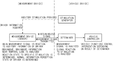
- FIG. 1 is a schematic view illustrating a vehicle system to adjust driving control authority, according to embodiments of the present disclosure
- FIG. 2 is a block diagram illustrating the vehicle system to adjust the driving control authority, according to embodiments of the present disclosure
- FIG. 3 is a view illustrating a position, at which a brainwave signal measured by a sensor device is generated, according to embodiments of the present disclosure
- FIGS. 4 to 7 are views illustrating devices having the sensor device, according to embodiments of the present disclosure.
- FIG. 8 is a graph illustrating the brainwave of the driver, which is used to adjust the driving control authority, according to embodiments of the present disclosure
- FIG. 9 is a graph illustrating the comparison between brainwave signals based on the driver state
- FIG. 10 is a flowchart illustrating a method for adjusting the driving control authority, according to embodiments of the present disclosure.
- FIG. 11 is a block diagram illustrating a computing system to execute the method, according to embodiments of the present disclosure.
- vehicle or “vehicular” or other similar term as used herein is inclusive of motor vehicles in general such as passenger automobiles including sports utility vehicles (SUV), buses, trucks, various commercial vehicles, watercraft including a variety of boats and ships, aircraft, and the like, and includes hybrid vehicles, electric vehicles, plug-in hybrid electric vehicles, hydrogen-powered vehicles and other alternative fuel vehicles (e.g., fuels derived from resources other than petroleum).
- a hybrid vehicle is a vehicle that has two or more sources of power, for example both gasoline-powered and electric-powered vehicles.
- vehicle controller may refer to a hardware device that includes a memory and a processor.
- the memory is configured to store program instructions, and the processor is specifically programmed to execute the program instructions to perform one or more processes which are described further below.
- the below methods may be executed by an apparatus comprising the vehicle controller in conjunction with one or more other components, as would be appreciated by a person of ordinary skill in the art.
- FIG. 1 is a schematic view illustrating a vehicle system to adjust driving control authority, according to embodiments of the present disclosure.
- a sensor of a measuring device measures a reaction signal (alternatively referred to herein as a “driver reaction signal”) in response to stimulation generated from a stimulation generator of a vehicle.
- the reaction signal to auditory information generated from the vehicle may be measured using brainwave information near the temporal lobe.
- the reaction signal may be measured using brainwave information near the frontal lobe, middle lobe, or occipital lobe, as well as the temporal lobe.
- an event related potential is extracted by processing the measured reaction signal and the determiner determines a driver state using a potential from the ERP, which has the maximum amplitude value after a specific time elapses from a time in which the stimulation is generated from the vehicle.
- the potential having the maximum amplitude value has different values in the cases that the driver states are the normal and abnormal states. Accordingly, if the maximum amplitude value is greater than or equal to the reference value, the driver state is determined to be the normal state. If the maximum amplitude value is less than the reference value, the driver state is determined to be the abnormal state.
- a vehicle controller may adjust the driving control authority of the vehicle depending on the result of the determiner. If the driver state is determined to be the normal state, the vehicle controller may control operation of the vehicle such that the vehicle performs any one of autonomous driving and manual driving. If the driver state is determined to be the abnormal state, the vehicle controller may adjust the driving control authority of the vehicle to perform any one of autonomous driving or emergency stop.
- FIG. 2 is a block diagram illustrating the vehicle system which adjusts the driving control authority according to embodiments of the present disclosure.
- the vehicle system which adjusts the driving control authority may include a measurement device 10 and a vehicle 20 .
- the measurement device 10 may include a sensor device 11 , a controller 12 , and a communication device 13 .
- FIG. 2 illustrates that the measurement device 10 wirelessly communicates with the vehicle 20 for the convenience of explanation, the present disclosure is not limited thereto.
- the measurement device 10 may be included in the vehicle 20 .
- the measurement device 10 may measure the reaction of a driver to the auditory information according to embodiments of the present disclosure.
- the measurement device 10 may measure brainwave information near the temporal lobe to determine the reaction state to specific stimulation, thereby determining whether the driver normally recognizes information.
- the sensor device 11 measure a reaction signal which reacts to stimulation (e.g., auditory stimulation) provided by the vehicle.
- the sensor device 11 may measure the reaction signal at the frontal lobe, the temporal lobe, the middle lobe, or the occipital lobe as illustrated in FIG. 3 .
- the reaction signal to the stimulation may be measured by using the brainwave of the driver.
- the sensor device 11 may be mounted in a headrest inside the vehicle, as illustrated in FIG. 4 . If proximity measurement is necessary, a sensor projects and directly or indirectly makes contact with a peripheral part of the temporal lobe to measure the brainwave.
- the brainwave of a person may be acquired from an event related potential (ERP), a steady state visually evoked potential (SSVEP), an event related synchronization (ERS), an event related desynchronization (ERD), a default mode network, or the combination thereof.
- ERP event related potential
- SSVEP steady state visually evoked potential
- ERS event related synchronization
- ERP event related desynchronization
- default mode network or the combination thereof.
- the sensor device 11 may be provided in one of a headset type or a hairband type, as illustrated in FIG. 5 .
- the sensor device 11 may be embedded in glasses, a headphone, or a cap, which is able to directly make contact with the human body, and the driver may put on the sensor device 11 .
- the sensor device 11 is not limited to the above-described embodiment, and may be included in a wearable device which minimizes the restriction to the driver.
- various bio-signal information may be used to react to a stimulation (e.g., visible or auditory stimulation) provided by the vehicle.
- a stimulation e.g., visible or auditory stimulation
- the bio-signal information may include a hear rate of the driver or gaze information (e.g., dispersion of gaze or return of gaze) of the driver increased depending on the level of tension based on the stimulation (e.g., auditory stimulation) provided by the vehicle.
- the sensor device 11 may be put on the wrist of the driver or provided in a wearable device to be put on the head of the driver to sense the heart rate of the driver as illustrated in FIG. 6 .
- the sensor device 11 may be provided in a steering wheel or a gear knob of the vehicle to sense the gaze information of the driver as illustrated in FIG. 7 .
- the controller 12 may allow the sensor device 11 to perform a sensing operation by receiving information from the vehicle 20 .
- the communication device 13 may transmit, to the vehicle 20 , information sensed by the sensor device 11 of the measurement device 10 in a wired manner or a wireless manner. In addition, the communication device 13 may receive information from the vehicle 20 .
- the vehicle 20 may include a stimulation generator 21 , a communication device 22 , a signal processor 23 , a learning device 24 , a determiner 25 , and a vehicle controller 26 .
- the stimulation generator 21 may be a device to provide auditory stimulation to the driver if the driver boards on the vehicle.
- the auditory stimulation may be a welcome sound, a seat belt warning sound or a vehicle start sound.
- the auditory stimulation may be a warning sound for carelessness.
- the stimulation generator 21 is not limited to devices which generate a sound for the auditory stimulation, but may include a device which generates a visible effect for visible stimulation.
- the communication unit 22 may receive information sensed by the sensor device 11 of the measurement device 10 in a wired manner or a wireless manner and may transmit the received information to the learning device 24 .
- the signal processor 23 processes brainwave information sensed by the sensor device 11 of the measurement device 10 .
- the signal processor 23 may include a filter 23 - 1 , a down-sampler 23 - 2 , and a feature point extractor 23 - 3 .
- the filter 23 - 1 may remove other frequency bands from the sensed brainwave information except meaningful frequency bands. Signals other than a brainwave signal may be treated as noise.
- the down-sampler 23 - 2 may improve system efficiency by utilizing an electro encephalo-gram (EEG) time point.
- EEG electro encephalo-gram
- the feature point extractor 23 - 3 may extract a meaningful ERP signal.
- the feature point extractor 23 - 3 may extract a P300 potential component from the ERP and may use the P300 potential component as a reaction signal of the driver to the stimulation of the present disclosure. The details thereof will be described below with reference to FIG. 8 .
- FIG. 8 is a graph illustrating the brainwave of the driver, which is used to adjust the driving control authority according to embodiments of the present disclosure.
- the P300 potential component of the ERP in the above-described brainwave of the person is not the physical characteristic of the stimulation but is related to the reaction of the person.
- the P300 potential component has a feature of representing that the brainwave signal rises or increases after about 300 ms (a dotted rectangular part) if the normal reaction is made to the auditory stimulation signal. Accordingly, even P300 potential components of brainwave #1 and brainwave #2 may be measured in patterns as illustrated in the graph of FIG. 8 .
- the feature point extractor 23 - 3 may extract the P300 potential component from the reaction signal of the driver to stimulation (e.g., auditory stimulation) generated from the vehicle, for example, the auditory stimulation such as a welcome sound or a seat-belt warning sound.
- stimulation e.g., auditory stimulation
- the auditory stimulation such as a welcome sound or a seat-belt warning sound.
- the determiner 25 determines whether the driver is in a normal state or an abnormal state by analyzing a main signal pattern (i.e., feature point) extracted from the brainwave signal based on the driver state. The details thereof will be described below with reference to FIG. 9 .
- FIG. 9 is a graph illustrating the comparison between brainwave signals based on the driver state.
- the brainwave signal based on the driver state may be determined by using the maximum amplitudes of the brainwave signals.
- the P300 potential component of the ERP has a feature of representing that the brainwave signal rises or increases after about 300 ms (a dotted rectangular part) if the normal reaction is made with respect to the auditory stimulation signal. Referring to FIG. 9 based on the above feature, it may be recognized that a dotted curve and a solid curve have the maximum amplitudes after about 300 ms from that the stimulation starts.
- the dotted curve represents the brainwave signal of a driver in a normal state and the solid curve represents the brainwave signal of the driver in a drunken state.
- the brainwave signals of the driver in the normal state and the drunken state have the maximum amplitudes after about 300 ms from that the abnormal stimulation starts.
- the brainwave signal of the driver in the drunken state is lower than the brainwave signal of the driver in the normal state in the maximum amplitude value. Accordingly, it may be understood that the driver is more insensitive to the stimulation from the outside in the abnormal state rather than the normal state. According to the present disclosure, for the convenience of explanation, if the maximum amplitude value is equal to or more than a reference value, it is assumed that the driver has the brainwave signal in the normal state. If the maximum amplitude value is less than the reference value, it is assumed that the driver has the brainwave signal in the abnormal state. Accordingly, as illustrated in FIG.
- the determiner 25 determines the driver to be in the normal state. In addition, if the maximum amplitude value of the brainwave signal of the driver is less than the reference value, the determiner 25 determines the driver to be in the abnormal state.
- the learning device 24 may learn information received from the determiner 25 .
- the learning device 24 may learn the determination result of the determiner using feature points extracted from the feature point extractor 23 - 3 through support vector machine (SVM), linear discriminant analysis (LDA), or a neural network.
- SVM support vector machine
- LDA linear discriminant analysis
- the learning is performed in that the driver state is the normal state. If the maximum amplitude value of the extracted P300 potential is less than the reference value, the learning is performed in that the driver state is the abnormal state.
- the vehicle controller 26 may control the vehicle to perform any one of autonomous driving or manual driving. However, if the driver state is determined to be the abnormal state, the vehicle controller 26 may control the vehicle to only autonomously drive instead of manual driving and may allow the driver to perform only the function related to movement to a destination. The vehicle controller 26 may control the vehicle to be switched into an emergency stop mode.
- FIG. 10 is a flowchart illustrating a method for adjusting the driving control authority according to embodiments of the present disclosure.
- the vehicle controller 26 generates auditory stimulation to a driver if the driver boards the vehicle (S 100 ).
- the auditory stimulation may include a welcome sound, a seat belt warning sound, or a vehicle start sound.
- the auditory stimulation may include a warning sound for carelessness of the driver.
- the vehicle controller 26 measures the reaction signal of a driver to the auditory stimulation (S 110 ).
- the reaction signal may be measured using the brainwave of the driver generated from the temporal lobe of the driver.
- the brainwave of a person may be acquired from an ERP, an SSVEP, an ERS, an ERD, a default mode network, or the combination thereof.
- a bio-signal reacting to the auditory stimulation may be used.
- the bio-signal information may include a heart rate of a driver or the gaze information (e.g., dispersion of gaze or return of gaze) of the driver.
- the vehicle controller 26 may perform signal processing for the reaction signal measured in operation S 110 (S 130 ).
- Operation S 130 may include performing filtering to remove noise from a signal other than the brainwave, performing down-sampling to improve the system efficiency by utilizing an EEG time point, and extracting the ERP.
- a P300 potential component serving as a feature point may be extracted from the ERP and may be used as the reaction signal of the driver to the stimulation according to the present disclosure.
- the P300 potential component of the ERP is not the physical characteristic of the stimulation but is related to the reaction of the person.
- the P300 potential component represents a pattern that the brainwave signal rises or increases after about 300 ms if the normal reaction is made to the auditory stimulation signal.
- the feature point extractor 23 - 3 may extract and use the P300 potential component as the reaction signal of the driver to stimulation (auditory stimulation) generated from the vehicle, for example, the auditory stimulation such as a welcome sound or a seat-belt warning sound.
- the auditory stimulation such as a welcome sound or a seat-belt warning sound.
- the vehicle controller 26 determines the driver state based on the signal processed in operation S 130 (S 140 ). If the maximum amplitude value of the signal (P300 potential) processed in operation S 130 is greater than or equal to a reference value, the vehicle controller 26 determines the driver to be in the normal state. If the maximum amplitude value of the signal (P300 potential) processed in operation S 130 is less than a reference value, the vehicle controller 26 determines the driver to be in the abnormal state
- the vehicle controller 26 adjusts the driving control authority based on the determination result in operation S 140 (S 150 ). If the driver state is determined to be the normal state, the vehicle controller 26 may adjust the driving control authority of the vehicle to perform any one of autonomous driving and manual driving. However, if the driver state is determined to be the abnormal state, the vehicle controller 26 may control operation of the vehicle such that the vehicle only performs autonomously driving instead of manual driving and may control the vehicle such that only the function related to movement to a destination is operated. The vehicle controller may also control the vehicle to be switched into an emergency stop mode.
- an emergency situation may occur to a driver while the driver personally drives a vehicle with driving control authority over the vehicle.
- the emergency situation of the driver is recognized by the sensor of the vehicle and an alarm sound is sent to the driver.
- the vehicle controller 26 forcibly deprives the driver of the driving control authority to prevent the driver from being involved in driving the vehicle and allows the system to have the driving control authority such that the vehicle autonomously drives.
- the vehicle controller 26 recognizes, in an initial stage, whether the driver perceives a welcome sound of the vehicle, a vehicle state check sound, or a seat belt warning sound of the vehicle generated when the driver boards the vehicle, and allows the vehicle to drive in any one of an autonomous driving mode and a manual driving mode.
- the vehicle enters the autonomous driving mode, the vehicle generates visible stimulation or auditory stimulation, and measures the reaction to the simulation. If the driver is determined in the normal state based on the reaction result to the stimulation, the vehicle may be switched into the manual driving mode. However, if the driver is determined in the abnormal state, the vehicle may be maintained in the autonomous driving mode instead of being switched into the manual driving mode.
- the vehicle may perform a function of measuring or determining the reaction of the driver to an alarm sound generated when the driver drives the vehicle carelessly. If the driver is determined to less perceive the alarm sound generated when the driver drives the vehicle carelessly, an autonomous driving function may be automatically (forcibly) activated. In addition, if the driver is determined to, to a lower extent, perceive the alarm sound generated when the driver drives the vehicle carelessly, a surrounding road environment is determined. If the surrounding road environment is determined to be safe, an emergency shoulder parking function and an emergency braking function may be activated. Accordingly, safety accident may be prevented from being caused due to the careless driving.
- FIG. 11 is a block diagram illustrating a computing system to execute the method according to embodiments of the present disclosure.
- a computing system 1000 may include at least one processor 1100 , a memory 1300 , a user interface input device 1400 , a user interface output device 1500 , a storage 1600 , and a network interface 1700 , which are connected with each other via a bus 1200 .
- the processor 1100 may be a central processing device (CPU) or a semiconductor device for processing instructions stored in the memory 1300 and/or the storage 1600 .
- Each of the memory 1300 and the storage 1600 may include various types of volatile or non-volatile storage media.
- the memory 1300 may include a read only memory (ROM) and a random access memory (RAM).
- the operations of the methods or algorithms described in connection with the embodiments disclosed in the present disclosure may be directly implemented with a hardware module, a software module, or the combinations thereof, executed by the processor 1100 .
- the software module may reside on a storage medium (i.e., the memory 1300 and/or the storage 1600 ), such as a RAM, a flash memory, a ROM, an erasable and programmable ROM (EPROM), an electrically EPROM (EEPROM), a register, a hard disc, a removable disc, or a compact disc-ROM (CD-ROM).
- the exemplary storage medium may be coupled to the processor 1100 .
- the processor 1100 may read out information from the storage medium and may write information in the storage medium.
- the storage medium may be integrated with the processor 1100 .
- the processor and storage medium may reside in an application specific integrated circuit (ASIC).
- the ASIC may reside in a user terminal.
- the processor and storage medium may reside as separate components of the user terminal.
- an assist function for the vehicle driving is automatically activated or the driving control authority is forcibly recovered from the driver, thereby preventing a safety accident.
Landscapes
- Engineering & Computer Science (AREA)
- Health & Medical Sciences (AREA)
- Life Sciences & Earth Sciences (AREA)
- Physics & Mathematics (AREA)
- Automation & Control Theory (AREA)
- Transportation (AREA)
- Mechanical Engineering (AREA)
- Biophysics (AREA)
- Molecular Biology (AREA)
- Biomedical Technology (AREA)
- Public Health (AREA)
- Animal Behavior & Ethology (AREA)
- Veterinary Medicine (AREA)
- Surgery (AREA)
- Heart & Thoracic Surgery (AREA)
- General Health & Medical Sciences (AREA)
- Medical Informatics (AREA)
- Pathology (AREA)
- Artificial Intelligence (AREA)
- Psychiatry (AREA)
- Human Computer Interaction (AREA)
- Mathematical Physics (AREA)
- Signal Processing (AREA)
- Physiology (AREA)
- Psychology (AREA)
- Computer Vision & Pattern Recognition (AREA)
- Fuzzy Systems (AREA)
- Evolutionary Computation (AREA)
- Child & Adolescent Psychology (AREA)
- Developmental Disabilities (AREA)
- Educational Technology (AREA)
- Hospice & Palliative Care (AREA)
- Social Psychology (AREA)
- Cardiology (AREA)
- Combustion & Propulsion (AREA)
- Chemical & Material Sciences (AREA)
- Acoustics & Sound (AREA)
- Radar, Positioning & Navigation (AREA)
- Remote Sensing (AREA)
- General Physics & Mathematics (AREA)
Abstract
Description
Claims (13)
Applications Claiming Priority (2)
| Application Number | Priority Date | Filing Date | Title |
|---|---|---|---|
| KR1020170160394A KR20190061726A (en) | 2017-11-28 | 2017-11-28 | System and method for adjusting drivingcontrol of vehicle |
| KR10-2017-0160394 | 2017-11-28 |
Publications (2)
| Publication Number | Publication Date |
|---|---|
| US20190161091A1 US20190161091A1 (en) | 2019-05-30 |
| US10864918B2 true US10864918B2 (en) | 2020-12-15 |
Family
ID=66634808
Family Applications (1)
| Application Number | Title | Priority Date | Filing Date |
|---|---|---|---|
| US16/025,096 Active 2039-03-18 US10864918B2 (en) | 2017-11-28 | 2018-07-02 | Vehicle and method for supporting driving safety thereof |
Country Status (3)
| Country | Link |
|---|---|
| US (1) | US10864918B2 (en) |
| KR (1) | KR20190061726A (en) |
| CN (1) | CN109835331A (en) |
Families Citing this family (17)
| Publication number | Priority date | Publication date | Assignee | Title |
|---|---|---|---|---|
| US11541895B2 (en) * | 2019-04-03 | 2023-01-03 | Industrial Technology Research Institute | Driving assistance system and driving assistance method |
| DE102019208970A1 (en) * | 2019-06-19 | 2020-12-24 | Zf Friedrichshafen Ag | Control device for use in a motor vehicle |
| DE102019208992A1 (en) * | 2019-06-19 | 2020-12-24 | Zf Friedrichshafen Ag | Control device for use in a motor vehicle |
| KR20210000876A (en) * | 2019-06-26 | 2021-01-06 | 현대자동차주식회사 | Vehicle controlling method and apparatus using error monitoring |
| KR20190090742A (en) * | 2019-07-11 | 2019-08-02 | 엘지전자 주식회사 | Drowsy-driving prevention method and drowsy-driving prevention system |
| KR102631160B1 (en) * | 2019-07-11 | 2024-01-30 | 엘지전자 주식회사 | Method and apparatus for detecting status of vehicle occupant |
| JP2021017109A (en) * | 2019-07-18 | 2021-02-15 | トヨタ自動車株式会社 | Remote driving system |
| KR102110153B1 (en) * | 2019-09-30 | 2020-06-09 | 주식회사 신양테크 | Sleepiness Suppression System And Method |
| FR3103373A1 (en) * | 2019-11-27 | 2021-05-28 | Thales | ENVIRONMENTAL MONITORING ASSISTANCE SYSTEM AND ASSOCIATED PROCESS |
| KR20210066317A (en) * | 2019-11-28 | 2021-06-07 | 현대자동차주식회사 | Apparatus and method for monitoring epilepsy driver using brain wave |
| KR20210074601A (en) * | 2019-12-12 | 2021-06-22 | 현대자동차주식회사 | Apparatus and method for controlling emergency driving situation using brain wave |
| CN112109718A (en) * | 2020-06-17 | 2020-12-22 | 上汽通用五菱汽车股份有限公司 | Vehicle control method, device and computer readable storage medium |
| KR20220020146A (en) * | 2020-08-11 | 2022-02-18 | 현대자동차주식회사 | Steering wheel |
| KR20220055214A (en) * | 2020-10-26 | 2022-05-03 | 현대자동차주식회사 | Advanced Driver Assistance System and Vehicle having the advanced Driver Assistance System |
| KR102585149B1 (en) * | 2020-11-30 | 2023-10-10 | 재단법인대구경북과학기술원 | Customized self-driving devices and methods based on deep learning using cognitive characteristics |
| CN116724339A (en) * | 2021-04-27 | 2023-09-08 | 深圳市大疆创新科技有限公司 | Fatigue driving monitoring method, device, traffic equipment and storage medium |
| CN113212458B (en) * | 2021-06-16 | 2022-08-26 | 北京地平线机器人技术研发有限公司 | Method and device for controlling vehicle driving state |
Citations (8)
| Publication number | Priority date | Publication date | Assignee | Title |
|---|---|---|---|---|
| JPH11185200A (en) | 1997-12-22 | 1999-07-09 | Mitsubishi Motors Corp | Method for judging conscious level of driver in automatic traveling controllable vehicle |
| US20110279676A1 (en) * | 2009-10-15 | 2011-11-17 | Panasonic Corporation | Driving attention amount determination device, method, and computer program |
| US8239015B2 (en) * | 2008-09-19 | 2012-08-07 | Panasonic Corporation | Distraction detection apparatus, distraction detection method, and computer program |
| WO2014092494A1 (en) * | 2012-12-14 | 2014-06-19 | 고려대학교 산학협력단 | Method and apparatus for controlling travelling object using brain waves |
| US9031729B2 (en) | 2012-11-29 | 2015-05-12 | Volkswagen Ag | Method and system for controlling a vehicle |
| KR20160050444A (en) | 2014-10-29 | 2016-05-11 | 주식회사 서연전자 | Vehicle System |
| KR101648017B1 (en) | 2015-03-23 | 2016-08-12 | 현대자동차주식회사 | Display apparatus, vehicle and display method |
| US20170303842A1 (en) * | 2014-09-25 | 2017-10-26 | Denso Corporation | Onboard system, vehicle control device, and program product for vehicle control device |
Family Cites Families (23)
| Publication number | Priority date | Publication date | Assignee | Title |
|---|---|---|---|---|
| CA2448806C (en) * | 2001-06-13 | 2011-10-18 | Compumedics Limited | Methods and apparatus for monitoring consciousness |
| US8391966B2 (en) * | 2009-03-16 | 2013-03-05 | Neurosky, Inc. | Sensory-evoked potential (SEP) classification/detection in the time domain |
| US8155736B2 (en) * | 2009-03-16 | 2012-04-10 | Neurosky, Inc. | EEG control of devices using sensory evoked potentials |
| US8698639B2 (en) * | 2011-02-18 | 2014-04-15 | Honda Motor Co., Ltd. | System and method for responding to driver behavior |
| KR101316497B1 (en) * | 2012-08-03 | 2013-10-10 | 현대자동차주식회사 | System and method for observing heart rate of passenger |
| DE102013206212A1 (en) * | 2013-04-09 | 2014-10-09 | Ford Global Technologies, Llc | Method for controlling a vehicle with temporarily autonomous vehicle guidance and control device |
| US8874301B1 (en) * | 2013-07-09 | 2014-10-28 | Ford Global Technologies, Llc | Autonomous vehicle with driver presence and physiological monitoring |
| KR101539302B1 (en) * | 2013-12-11 | 2015-07-30 | 현대자동차주식회사 | Vehicle and control method for the same |
| CN103770733B (en) * | 2014-01-15 | 2017-01-11 | 中国人民解放军国防科学技术大学 | Method and device for detecting safety driving states of driver |
| MX358325B (en) * | 2014-03-26 | 2018-08-15 | Nissan Motor | Information presentation device and information presentation method. |
| CN106687026A (en) * | 2014-05-12 | 2017-05-17 | 汽车技术国际公司 | Driver health and fatigue monitoring system and method |
| KR101612824B1 (en) * | 2014-11-20 | 2016-04-15 | 현대자동차주식회사 | Method and apparatus for Monitoring Driver Status using Head Mounted Display |
| CN104434066A (en) * | 2014-12-05 | 2015-03-25 | 上海电机学院 | Physiologic signal monitoring system and method of driver |
| US10331127B2 (en) * | 2014-12-12 | 2019-06-25 | Sony Corporation | Automatic driving control device and automatic driving control method, and program |
| CN105054951B (en) * | 2015-08-11 | 2019-05-31 | 西安科技大学 | A kind of fatigue driving eeg monitoring method based on frequency of wink identification |
| US10349892B2 (en) * | 2015-11-24 | 2019-07-16 | Hyundai Dymos Incorporated | Biological signal measuring system based on driving environment for vehicle seat |
| CN105599607B (en) * | 2016-02-05 | 2019-03-26 | 长安大学 | A kind of vehicle starting device and method based on driver status |
| CN107200022B (en) * | 2016-03-15 | 2019-11-12 | 奥迪股份公司 | Driving assistance system and method |
| JP6699831B2 (en) * | 2016-04-28 | 2020-05-27 | トヨタ自動車株式会社 | Driving awareness estimation device |
| CN105966409A (en) * | 2016-06-08 | 2016-09-28 | 捷开通讯(深圳)有限公司 | Safety driving method and system |
| CN106515706A (en) * | 2016-09-30 | 2017-03-22 | 广州汽车集团股份有限公司 | Vehicle safety driving control method and vehicle safety driving control system |
| CN106781581A (en) * | 2016-11-29 | 2017-05-31 | 深圳职业技术学院 | Safe driving behavior monitoring early warning system and method based on the coupling of people's car |
| CN107336711A (en) * | 2017-06-19 | 2017-11-10 | 北京汽车股份有限公司 | Vehicle and its automated driving system and method |
-
2017
- 2017-11-28 KR KR1020170160394A patent/KR20190061726A/en not_active IP Right Cessation
-
2018
- 2018-07-02 US US16/025,096 patent/US10864918B2/en active Active
- 2018-07-20 CN CN201810809379.9A patent/CN109835331A/en active Pending
Patent Citations (9)
| Publication number | Priority date | Publication date | Assignee | Title |
|---|---|---|---|---|
| JPH11185200A (en) | 1997-12-22 | 1999-07-09 | Mitsubishi Motors Corp | Method for judging conscious level of driver in automatic traveling controllable vehicle |
| US8239015B2 (en) * | 2008-09-19 | 2012-08-07 | Panasonic Corporation | Distraction detection apparatus, distraction detection method, and computer program |
| US20110279676A1 (en) * | 2009-10-15 | 2011-11-17 | Panasonic Corporation | Driving attention amount determination device, method, and computer program |
| US9031729B2 (en) | 2012-11-29 | 2015-05-12 | Volkswagen Ag | Method and system for controlling a vehicle |
| WO2014092494A1 (en) * | 2012-12-14 | 2014-06-19 | 고려대학교 산학협력단 | Method and apparatus for controlling travelling object using brain waves |
| US20170303842A1 (en) * | 2014-09-25 | 2017-10-26 | Denso Corporation | Onboard system, vehicle control device, and program product for vehicle control device |
| KR20160050444A (en) | 2014-10-29 | 2016-05-11 | 주식회사 서연전자 | Vehicle System |
| KR101648017B1 (en) | 2015-03-23 | 2016-08-12 | 현대자동차주식회사 | Display apparatus, vehicle and display method |
| US20160282940A1 (en) | 2015-03-23 | 2016-09-29 | Hyundai Motor Company | Display apparatus, vehicle and display method |
Non-Patent Citations (1)
| Title |
|---|
| Espacenet translation of WO2014092494A1, Method and Apparatus for Controlling Travelling Object Using Brain Waves, Kim et al, WIPO/PCT Publication, 12 pages (Year: 2014). * |
Also Published As
| Publication number | Publication date |
|---|---|
| CN109835331A (en) | 2019-06-04 |
| US20190161091A1 (en) | 2019-05-30 |
| KR20190061726A (en) | 2019-06-05 |
Similar Documents
| Publication | Publication Date | Title |
|---|---|---|
| US10864918B2 (en) | Vehicle and method for supporting driving safety thereof | |
| US10210409B1 (en) | Seating system with occupant stimulation and sensing | |
| US20210009149A1 (en) | Distractedness sensing system | |
| US10343520B1 (en) | Systems and methodologies for real-time driver gaze location determination and analysis utilizing computer vision technology | |
| US10379535B2 (en) | Drowsiness sensing system | |
| EP2564765B1 (en) | System and method for improving a performance estimation of an operator of a vehicle | |
| US10160456B2 (en) | Apparatus and method for controlling vehicle based on degree of fatigue | |
| CN106963348B (en) | Biosignal measurement system for vehicle seat based on driving environment | |
| EP2743118A1 (en) | Method, system and computer readable medium with instructions to adjust insurance rate based on real-time data about potential vehicle operator impairment | |
| CN107554528B (en) | Fatigue grade detection method and device for driver and passenger, storage medium and terminal | |
| WO2015175435A1 (en) | Driver health and fatigue monitoring system and method | |
| DE102014209071A1 (en) | MOBILE PHONE CAMERA FOR DRIVER STATUS ESTIMATION | |
| CN104276037B (en) | Limitation or the method and apparatus for forcing activation vehicle function | |
| Melnicuk et al. | Towards hybrid driver state monitoring: Review, future perspectives and the role of consumer electronics | |
| US11813060B2 (en) | System and method for biometric evoked response monitoring and feedback | |
| US20150125126A1 (en) | Detection system in a vehicle for recording the speaking activity of a vehicle occupant | |
| US11751784B2 (en) | Systems and methods for detecting drowsiness in a driver of a vehicle | |
| US20200122746A1 (en) | Vehicle driving control system and vehicle driving control method | |
| US20220036101A1 (en) | Methods, systems and computer program products for driver monitoring | |
| Kumar et al. | Detecting distraction in drivers using electroencephalogram (EEG) signals | |
| KR20170036168A (en) | System and method for monitoring driver condition | |
| CN116552542A (en) | Vehicle control method, device, electronic equipment and storage medium | |
| Rumagit et al. | Gazing time analysis for drowsiness assessment using eye gaze tracker | |
| US11383640B2 (en) | Techniques for automatically reducing annoyance levels of drivers when using driver monitoring systems | |
| KR20220063952A (en) | System for preventing drowsy driving based on brain engineering |
Legal Events
| Date | Code | Title | Description |
|---|---|---|---|
| AS | Assignment |
Owner name: HYUNDAI MOTOR COMPANY, KOREA, REPUBLIC OF Free format text: ASSIGNMENT OF ASSIGNORS INTEREST;ASSIGNOR:AN, DAE YUN;REEL/FRAME:046250/0863 Effective date: 20180102 Owner name: KIA MOTORS CORPORATION, KOREA, REPUBLIC OF Free format text: ASSIGNMENT OF ASSIGNORS INTEREST;ASSIGNOR:AN, DAE YUN;REEL/FRAME:046250/0863 Effective date: 20180102 |
|
| FEPP | Fee payment procedure |
Free format text: ENTITY STATUS SET TO UNDISCOUNTED (ORIGINAL EVENT CODE: BIG.); ENTITY STATUS OF PATENT OWNER: LARGE ENTITY |
|
| STPP | Information on status: patent application and granting procedure in general |
Free format text: DOCKETED NEW CASE - READY FOR EXAMINATION |
|
| STPP | Information on status: patent application and granting procedure in general |
Free format text: NON FINAL ACTION MAILED |
|
| STPP | Information on status: patent application and granting procedure in general |
Free format text: RESPONSE TO NON-FINAL OFFICE ACTION ENTERED AND FORWARDED TO EXAMINER |
|
| STPP | Information on status: patent application and granting procedure in general |
Free format text: NOTICE OF ALLOWANCE MAILED -- APPLICATION RECEIVED IN OFFICE OF PUBLICATIONS |
|
| STPP | Information on status: patent application and granting procedure in general |
Free format text: PUBLICATIONS -- ISSUE FEE PAYMENT VERIFIED |
|
| STCF | Information on status: patent grant |
Free format text: PATENTED CASE |
|
| MAFP | Maintenance fee payment |
Free format text: PAYMENT OF MAINTENANCE FEE, 4TH YEAR, LARGE ENTITY (ORIGINAL EVENT CODE: M1551); ENTITY STATUS OF PATENT OWNER: LARGE ENTITY Year of fee payment: 4 |