US10864828B2 - Side-by-side ATV - Google Patents
Side-by-side ATV Download PDFInfo
- Publication number
- US10864828B2 US10864828B2 US14/478,689 US201414478689A US10864828B2 US 10864828 B2 US10864828 B2 US 10864828B2 US 201414478689 A US201414478689 A US 201414478689A US 10864828 B2 US10864828 B2 US 10864828B2
- Authority
- US
- United States
- Prior art keywords
- engine
- vehicle
- frame
- assembly
- coupled
- Prior art date
- Legal status (The legal status is an assumption and is not a legal conclusion. Google has not performed a legal analysis and makes no representation as to the accuracy of the status listed.)
- Active
Links
- 230000005540 biological transmission Effects 0.000 claims description 35
- 239000000725 suspension Substances 0.000 claims description 28
- 230000000712 assembly Effects 0.000 claims description 9
- 238000000429 assembly Methods 0.000 claims description 9
- 239000002828 fuel tank Substances 0.000 claims description 7
- 230000008878 coupling Effects 0.000 claims 4
- 238000010168 coupling process Methods 0.000 claims 4
- 238000005859 coupling reaction Methods 0.000 claims 4
- 241000083700 Ambystoma tigrinum virus Species 0.000 description 116
- AXRYRYVKAWYZBR-GASGPIRDSA-N atazanavir Chemical compound C([C@H](NC(=O)[C@@H](NC(=O)OC)C(C)(C)C)[C@@H](O)CN(CC=1C=CC(=CC=1)C=1N=CC=CC=1)NC(=O)[C@@H](NC(=O)OC)C(C)(C)C)C1=CC=CC=C1 AXRYRYVKAWYZBR-GASGPIRDSA-N 0.000 description 67
- 230000033001 locomotion Effects 0.000 description 6
- 230000001681 protective effect Effects 0.000 description 6
- 238000001816 cooling Methods 0.000 description 5
- 239000012530 fluid Substances 0.000 description 4
- 238000009434 installation Methods 0.000 description 4
- 230000005484 gravity Effects 0.000 description 3
- 230000006378 damage Effects 0.000 description 2
- 239000003381 stabilizer Substances 0.000 description 2
- 229910000831 Steel Inorganic materials 0.000 description 1
- 208000027418 Wounds and injury Diseases 0.000 description 1
- 230000001133 acceleration Effects 0.000 description 1
- 230000004913 activation Effects 0.000 description 1
- 230000006978 adaptation Effects 0.000 description 1
- 210000001217 buttock Anatomy 0.000 description 1
- 238000010276 construction Methods 0.000 description 1
- 230000000694 effects Effects 0.000 description 1
- 229920001971 elastomer Polymers 0.000 description 1
- 239000000806 elastomer Substances 0.000 description 1
- 210000003414 extremity Anatomy 0.000 description 1
- 208000014674 injury Diseases 0.000 description 1
- 230000003993 interaction Effects 0.000 description 1
- 238000012423 maintenance Methods 0.000 description 1
- 239000000463 material Substances 0.000 description 1
- 239000012858 resilient material Substances 0.000 description 1
- 230000004043 responsiveness Effects 0.000 description 1
- 239000010959 steel Substances 0.000 description 1
- 238000003466 welding Methods 0.000 description 1
Images


Classifications
-
- B—PERFORMING OPERATIONS; TRANSPORTING
- B60—VEHICLES IN GENERAL
- B60N—SEATS SPECIALLY ADAPTED FOR VEHICLES; VEHICLE PASSENGER ACCOMMODATION NOT OTHERWISE PROVIDED FOR
- B60N2/00—Seats specially adapted for vehicles; Arrangement or mounting of seats in vehicles
- B60N2/005—Arrangement or mounting of seats in vehicles, e.g. dismountable auxiliary seats
- B60N2/01—Arrangement of seats relative to one another
-
- B—PERFORMING OPERATIONS; TRANSPORTING
- B62—LAND VEHICLES FOR TRAVELLING OTHERWISE THAN ON RAILS
- B62D—MOTOR VEHICLES; TRAILERS
- B62D21/00—Understructures, i.e. chassis frame on which a vehicle body may be mounted
- B62D21/18—Understructures, i.e. chassis frame on which a vehicle body may be mounted characterised by the vehicle type and not provided for in groups B62D21/02 - B62D21/17
- B62D21/183—Understructures, i.e. chassis frame on which a vehicle body may be mounted characterised by the vehicle type and not provided for in groups B62D21/02 - B62D21/17 specially adapted for sports vehicles, e.g. race, dune buggies, go-karts
-
- B—PERFORMING OPERATIONS; TRANSPORTING
- B60—VEHICLES IN GENERAL
- B60K—ARRANGEMENT OR MOUNTING OF PROPULSION UNITS OR OF TRANSMISSIONS IN VEHICLES; ARRANGEMENT OR MOUNTING OF PLURAL DIVERSE PRIME-MOVERS IN VEHICLES; AUXILIARY DRIVES FOR VEHICLES; INSTRUMENTATION OR DASHBOARDS FOR VEHICLES; ARRANGEMENTS IN CONNECTION WITH COOLING, AIR INTAKE, GAS EXHAUST OR FUEL SUPPLY OF PROPULSION UNITS IN VEHICLES
- B60K17/00—Arrangement or mounting of transmissions in vehicles
- B60K17/34—Arrangement or mounting of transmissions in vehicles for driving both front and rear wheels, e.g. four wheel drive vehicles
- B60K17/348—Arrangement or mounting of transmissions in vehicles for driving both front and rear wheels, e.g. four wheel drive vehicles having differential means for driving one set of wheels, e.g. the front, at one speed and the other set, e.g. the rear, at a different speed
- B60K17/35—Arrangement or mounting of transmissions in vehicles for driving both front and rear wheels, e.g. four wheel drive vehicles having differential means for driving one set of wheels, e.g. the front, at one speed and the other set, e.g. the rear, at a different speed including arrangements for suppressing or influencing the power transfer, e.g. viscous clutches
-
- B—PERFORMING OPERATIONS; TRANSPORTING
- B60—VEHICLES IN GENERAL
- B60K—ARRANGEMENT OR MOUNTING OF PROPULSION UNITS OR OF TRANSMISSIONS IN VEHICLES; ARRANGEMENT OR MOUNTING OF PLURAL DIVERSE PRIME-MOVERS IN VEHICLES; AUXILIARY DRIVES FOR VEHICLES; INSTRUMENTATION OR DASHBOARDS FOR VEHICLES; ARRANGEMENTS IN CONNECTION WITH COOLING, AIR INTAKE, GAS EXHAUST OR FUEL SUPPLY OF PROPULSION UNITS IN VEHICLES
- B60K5/00—Arrangement or mounting of internal-combustion or jet-propulsion units
- B60K5/10—Arrangement or mounting of internal-combustion or jet-propulsion units providing for ready detachment of engine
-
- B—PERFORMING OPERATIONS; TRANSPORTING
- B60—VEHICLES IN GENERAL
- B60K—ARRANGEMENT OR MOUNTING OF PROPULSION UNITS OR OF TRANSMISSIONS IN VEHICLES; ARRANGEMENT OR MOUNTING OF PLURAL DIVERSE PRIME-MOVERS IN VEHICLES; AUXILIARY DRIVES FOR VEHICLES; INSTRUMENTATION OR DASHBOARDS FOR VEHICLES; ARRANGEMENTS IN CONNECTION WITH COOLING, AIR INTAKE, GAS EXHAUST OR FUEL SUPPLY OF PROPULSION UNITS IN VEHICLES
- B60K5/00—Arrangement or mounting of internal-combustion or jet-propulsion units
- B60K5/12—Arrangement of engine supports
-
- B—PERFORMING OPERATIONS; TRANSPORTING
- B62—LAND VEHICLES FOR TRAVELLING OTHERWISE THAN ON RAILS
- B62D—MOTOR VEHICLES; TRAILERS
- B62D33/00—Superstructures for load-carrying vehicles
- B62D33/06—Drivers' cabs
- B62D33/0617—Drivers' cabs for tractors or off-the-road vehicles
Definitions
- the present invention relates to side-by-side all terrain vehicles having at least a pair of laterally spaced apart seating surfaces. More particularly, the present invention relates to trail compliant side-by-side all terrain vehicles.
- ATVs all terrain vehicles
- UVs utility vehicles
- ATVs all terrain vehicles
- ATVs utility vehicles
- ATVs are used to carry one or two passengers and a small amount of cargo over a variety of terrains.
- specialty ATVs such as those used for trail riding, racing, and cargo hauling have entered the market place.
- Most ATVs include seating for up to two passengers which are either seated side-by-side or with the passenger positioned behind the driver of the ATV.
- Side-by-side ATVs in which the driver and passenger are seated beside each other on laterally spaced apart seats, have become popular because of the ability to allow the passenger to share the driver's viewpoint and riding experience instead of being positioned behind the driver.
- an all-terrain vehicle includes a frame, comprising a front frame portion, a mid frame portion and a rear frame portion, the rear frame portion comprising a lower rear frame portion and an upper rear frame portion.
- a front suspension is coupled to the front frame portion and at least two front wheels are coupled to the front suspension.
- a rear suspension is coupled to the rear frame portion and at least two rear wheels are coupled to the rear suspension.
- a cab is intermediate the front and rear wheels and a seating area is within the cab and supported by the mid frame portion, comprising side by side seats each having a seat back and a seat bottom.
- An engine is supported by the rear frame portion, the engine is positioned rearwardly of the seating area, and each seat bottom has a seating surface with a low point of the seating surface being below a top of the engine, the spaced-apart seating surfaces including a driver seating surface and a passenger seating surface.
- a fuel tank is positioned underneath one of the seat bottoms.
- a transmission comprising a continuously variable transmission is positioned rearwardly of the seating area and the front and rear wheels are drivingly coupled to the transmission.
- the lower rear frame portion supports at least one of the engine and transmission rearward of the seating area. Outermost points of the vehicle in a width-wise direction define a width of less than 54 inches.
- an all-terrain vehicle comprises a frame, a front suspension coupled to the frame, and at least two front wheels coupled to the front suspension.
- a rear suspension is coupled to the frame and at least two rear wheels are coupled to the rear suspension.
- a cab is intermediate the front and rear wheels and a seating area is within the cab and is supported by the frame, comprising side by side seats each having a seat back and a seat bottom.
- a rear axle assembly drivingly couples the transmission to the rear wheels.
- a modular engine assembly is supported by the frame rearward of the seating area, the modular engine assembly being comprised of an engine, a transmission comprising a continuously variable transmission, and at least a portion of the rear axle assembly, wherein the modular engine assembly is capable of being mounted to or dismounted from the frame as a unit.
- a front axle assembly is supported by the frame and drivingly couples the transmission to the front wheels. Outermost points of the vehicle in a width-wise direction define a width of less than 54 inches.
- FIG. 1 is a perspective view of one embodiment of a side-by-side ATV
- FIG. 2 is a profile view of the side-by-side ATV shown in FIG. 1 ;
- FIG. 3 is a front view of the ATV shown in FIGS. 1 and 2 ;
- FIG. 4 is a top plan view of the side-by-side ATV shown in FIGS. 1 through 3 ;
- FIG. 5 is a partial perspective view of the cab area of the side-by-side ATV shown in FIGS. 1 through 4 ;
- FIG. 6 is a partial profile view of the cab area shown in FIG. 5 ;
- FIG. 7 is a partial perspective view of one embodiment of a guard rail that may be used on a side-by-side ATV, such as the side-by-side ATV shown in FIG. 1 ;
- FIG. 8 is another embodiment of a guard rail that may be used on a side-by-side ATV, such as the side-by-side ATV shown in FIG. 1 ;
- FIG. 9 is a bottom plan view of the side-by-side ATV shown in FIGS. 1 through 4 ;
- FIG. 10 is a partially exploded, perspective view of the front end of the ATV shown in FIGS. 1 through 4 ;
- FIG. 11 is a partially exploded, perspective view similar to FIG. 10 showing hood mounting details
- FIG. 12 is a cross-sectional view illustrating the hood mounting with the hood partially removed from the front panel
- FIG. 13 is a cross-sectional view similar to FIG. 12 with the hood coupled to the front panel;
- FIG. 14 is a rear perspective view of the frame and the modular engine assembly of the side-by-side ATV shown in FIGS. 1 through 4 ;
- FIG. 15 is a partially exploded, rear perspective view of the frame and modular engine assemblies shown in FIG. 14 ;
- FIG. 16 is an exploded perspective view of one embodiment of an engine mounting assembly that may be used on an ATV such as the side-by-side ATV shown in FIGS. 1 through 4 ;
- FIG. 17 is an exploded perspective view of another embodiment of an engine mounting assembly that may be used on an ATV such as the side-by-side ATV shown in FIGS. 1 through 4 ;
- FIG. 18 is an exploded perspective view of yet another embodiment of an engine mounting assembly that may be used on an ATV such as the side-by-side ATV shown in FIGS. 1 through 4 ;
- FIG. 19 is a partial front perspective view of the bottom side of the drive train components of the side-by-side ATV shown in FIGS. 1 through 4 ;
- FIG. 20 is a partially exploded rear view of components of the frame and rear suspension system of the side-by-side ATV shown in FIGS. 1 through 4 ;
- FIG. 21 is a rear view of the frame and suspension system of the ATV shown in FIG. 20 ;
- FIG. 22 is a partial rear perspective view of a steering mechanism and front axle assembly that may be used on an ATV such as the side-by-side ATV shown in FIGS. 1 through 4 ;
- FIG. 23 is a partial front perspective view of the steering mechanism and front axle assembly of the ATV shown in FIG. 22 ;
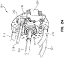
- FIG. 24 is a partial perspective view of one embodiment of a braking assembly that may be used on an ATV such as the side-by-side ATV shown in FIGS. 1 through 4 ;
- FIG. 25 is an elevated rear perspective view of the engine and clutch cooling components of the side-by-side ATV shown in FIGS. 1 through 4 ;
- FIG. 26 is a partial rear view of the engine and clutch cooling components shown in FIG. 25 ;
- FIG. 27 is a partial perspective view of the driver's side foot well area of the ATV shown in FIGS. 1 through 4 ;
- FIG. 28 is an partial exploded view of a steering assembly that may be used on an ATV such as the side-by-side ATV shown in FIGS. 1 through 4 ;
- FIG. 29 is a side elevational view of the steering assembly of FIG. 28 , showing the steering wheel in various tilted positions;
- FIG. 30 is a partial perspective view of an adjustable grab bar that may be used on an ATV such as the side-by-side ATV shown in FIGS. 1 through 4 .
- ATV 10 includes front end 12 and rear end 14 , and a frame 15 which is supported above the ground surface by a pair of front tires 22 a and wheels 24 a and a pair of rear tires 22 b and wheels 24 b .
- ATV 10 includes a pair of laterally spaced-apart upper and lower seating surfaces 18 a , 18 b and 20 a , 20 b , respectively.
- the upper seating surfaces 18 a , 18 b are configured to support the backs of sitting riders, while the lower seating surfaces 20 a , 20 b are configured to support the buttocks of sitting riders.
- upper and lower seating surfaces 18 a , 18 b , and 20 a , 20 b form a bucket seat arrangement, however a bench style seat or any other style of seating structure may be used.
- Upper and lower seating surfaces 18 and 20 are positioned within cab 17 of ATV 10 .
- Protective cage 16 extends over cab 17 to assist in preventing injury to passengers of ATV 10 from passing branches or tree limbs, as well as, may act as a support in the event of a vehicle rollover. As shown in FIGS. 1 through 4 , protective cage 17 narrows as it extends upwardly to allow the driver and passenger easier entry and exit of cab 17 . Additionally, in some embodiments a cover including one or more of a roof, windshield and doors (not shown) may be attached to the protective cage 16 to block weathering elements such as wind, rain or snow.
- Cab 17 also includes front console 31 , adjustable steering wheel 28 , and shift lever 29 . Front console 31 may include a tachometer, speedometer, or any other suitable instrument.
- Front end 12 of ATV 10 includes front panel 67 , hood 32 , and front suspension assembly 26 .
- Front suspension assembly 26 pivotally couples front wheels 24 to ATV 10 .
- Rear end 14 of ATV 10 includes engine cover 19 which extends over modular engine assembly 34 , as shown in FIGS. 2, 14, and 15 .
- Modular engine assembly 34 is illustratively positioned completely behind upper and lower seating surfaces 18 a , 18 b , and 20 a , 20 b.
- front wheels 24 are supported for rotation by front axle 36 .
- rear wheels 24 b are supported for rotation by rear axle 38 .
- wheelbase A which extends between the center of front axle 36 and the center of rear axle 38 , is equal to about 77 inches (195.6 centimeters).
- Seat height B is equal to the distance between a low point 21 of lower seating surfaces 20 and a bottom of the frame 15 when ATV 10 is at rest. In the illustrative embodiment, seat height B is equal to about 11.75 inches (29.8 centimeters).
- the ratio of the wheelbase to the seat height, or distance A to distance B is about 6.55 to 1.
- the ratio of the wheelbase to the seat height may be equal to other suitable ratios, however the present invention contemplates ATVs having a ratio of wheelbase to seat height greater than about 6.0 to 1.
- a wheelbase to seat height ratio greater than about 6.0 to 1 facilitates a relatively low vehicle center of gravity and further provides improved ergonomics, handling, and space utilization.
- width C which is defined as the overall width of ATV 10 , extends between the outermost lateral points of ATV 10 .
- outer surfaces of tires 22 on the front and rear ends of ATV 10 define the outermost points.
- width C may be measured from the outer fenders of front panel 67 . It may be appreciated that width C may be defined by both the outer surfaces of tires 22 and fenders of front panel 67 , should the respective dimensions be substantially equal.
- width C is about 50 inches.
- ATV 10 may be constructed to other suitable widths, however the present invention contemplates ATVs having a trail compliant width or less than about 54 inches.
- Foot well area 40 extends below base 41 and encloses each passenger's feet and lower leg portions.
- Foot well area 40 includes floorboard 42 and side panel 46 on each side of ATV 10 .
- Floorboard 42 includes an aperture 44 positioned to allow fluid to drain out of floorboard 42 .
- Side panel 46 extends upwardly from floorboards 42 on each side of ATV 10 . In the illustrative embodiment, side panels 46 extend upward about 4 inches (10.2 centimeters) from floorboards 42 , however side panels 46 may be constructed to any suitable height.
- Side panels 46 and foot well areas 40 prevent the feet and lower leg portions of the driver and passenger of ATV 10 from moving outside of cab 17 when ATV 10 is in motion, for example when traversing rough terrain. In other embodiments (not shown), side panels 46 may be removed to allow easier entry and exit into cab 17 of ATV 10 .
- ATV 48 includes driver's side seat 49 , side panel 52 , and engine cover 54 .
- Tube 56 extends upward from engine cover 54 to form protective cage 16 .
- Seat guard 50 is coupled between engine cover 54 and side panel 52 to prevent a passenger positioned on seat 49 from sliding laterally off of seat 49 during vigorous driving. Additionally, seat guard 50 may provide protection against passing external obstacles. Seat guard 50 may also be included on the passenger's side of ATV 48 .
- safety bar 58 couples between tube 56 and seat guard 50 to further enclose a passenger in the cab area of ATV 48 .
- safety bar 58 may be used as a handle when entering or exiting ATV 48 .
- Safety bar 58 may also be included on the passenger's side of ATV 48 .
- there may be a panel or restrictive member, such as a mesh netting, placed between one or more of seat guard 50 , safety bar 58 , tube 56 and side panel 52 to further restrict the driver's or passenger's appendages from exiting the vehicle during vigorous driving.
- FIG. 9 an illustrative bottom plan view of ATV 10 is shown.
- driver's side 65 of ATV 10 is shown on the upper portion of FIG. 9 and passenger's side 63 is shown on the lower portion of FIG. 9 .
- Longitudinal axis 66 separates driver's side 65 from passenger's side 63 and defines the longitudinal center line of ATV 10 .
- various relatively heavy components are positioned vertically proximate the frame 15 to lower the vehicle's center of gravity, thereby improving balance and stability.
- fuel tank 62 is positioned under lower seating surface 20 b on passenger's side 63 of ATV 10 .
- Fuel tank 62 is supported by frame 15 . As shown, fuel tank 62 is L-shaped, however any suitably shaped fuel tank may be used. Positioning fuel tank 62 on passenger's side 63 improves the balance of ATV 10 when only a driver is present on driver's side 65 of ATV 10 . Battery 64 is positioned under lower seating surface 20 a on driver's side 65 of ATV 10 . In this embodiment, battery 64 is positioned near axis 66 and relatively low on the ATV 10 , thereby improving balance. Positioning of battery 64 near the seating surface 20 a also allows for easier serviceability and for reduced routing of lines to the engine assembly 34 .
- Front end 12 includes hood 32 , which may be removably coupled to front panel 67 .
- a hood mounting assembly includes a pair of plungers or pegs 95 which are removably received within cylindrical grommets 97 .
- Plungers 95 are fixed near the rear corners of the hood 32
- grommets 97 are fixed to the front panel 67 near the rear corners of a storage area 68 .
- plungers 95 and grommets 97 are illustratively formed of steel and a resilient material (such as an elastomer), respectively, however any suitable material may be used.
- the front of hood 32 includes a plurality of flanges 99 a which are configured to cooperate with a lip 99 b formed within front panel 67 , thereby defining a releasable hinge.
- storage area 68 and access panel 61 are positioned under hood 32 .
- Storage area 68 may receive a tool kit, cargo net or any other suitable vehicle accessory for ATV 10 .
- Access panel 61 may include any suitable engine or vehicle maintenance port or terminal, such as a radiator fill cap, battery charging terminals, oil fill plug, or transmission fill plug.
- Frame 15 of a side-by-side ATV such as ATV 10 shown in FIG. 1 is shown.
- Frame 15 includes inner rails 72 , front crossmember 71 , mid crossmember 73 , and rear crossmember 77 .
- Frame 15 also includes outer tubes 70 that define the outermost width of frame 15 .
- Rear assembly 92 is coupled to upper frame rails 90 and cross-member 77 and is described in more detail below.
- the portion of frame 15 between mid crossmember 73 and rear crossmember 77 supports modular engine assembly 34 of ATV 10 .
- modular engine assembly 34 may include a transmission 136 such as a continuously variable transmission, and a rear differential 132 prior to being installed in frame 15 , as shown in FIG. 15 .
- inner rails 72 of frame 15 are coupled together on a front end by crossmember 71 and on the rear end by rear crossmember 77 .
- Brackets 76 couple upper frame tubes 88 , upper frame rails 90 , vertical tubes 74 , and outer tubes 70 together on each side of ATV 10 .
- Outer tubes 70 are coupled to inner rails 72 by brackets 69 .
- Vertical tubes 74 are coupled on a lower end to inner rails 72 .
- Upper frame tubes 88 are coupled to support tubes 83 which are coupled on a lower end to inner rails 72 .
- Upper frame rails 90 are coupled on a rear end to cross tube 91 .
- modular engine assembly 34 may be preassembled before being installed in frame 15 .
- upper brace 78 is attached to frame 15 to provide dimensional stability during welding.
- upper brace 78 is removed from frame 15 and modular engine assembly 34 is placed on frame 15 .
- Upper brace 78 is then reattached to frame 15 . More particularly, after modular engine assembly 34 is positioned between upper frame rails 90 in frame 15 , as shown in FIG. 14 , upper brace 78 may be installed.
- Upper brace 78 includes outer brackets 86 , rear bracket 84 , crossmember 80 and angular members 82 .
- Angular members 82 are coupled together on an end by bracket 84 and on an opposing end by crossmember 80 .
- Each bracket 86 is substantially U-shaped and includes apertures 85 .
- U-shaped brackets 86 are adapted to overlap upper frame tubes 88 .
- Apertures 85 in brackets 86 and apertures 87 in upper frame tubes 88 align and accept fasteners to secure upper brace 78 to upper frame tubes 88 .
- Bracket 84 includes apertures 81 which align with aperture 89 in cross tube 91 and may be secured using any suitable fasteners.
- modular engine assembly 34 is mounted on frame 15 of ATV 10 using a three position mounting system to allow modular engine assembly 34 to be dropped into frame 15 and bolted or attached as one unit. Illustrative embodiments of each of the three mounting assemblies are shown in FIGS. 16 through 18 .
- mounting system 94 positioned on the driver's side of modular engine assembly 34 and frame 15 is shown.
- Bracket 96 is mounted to modular engine assembly 34 prior to installation of modular engine assembly 34 in frame 15 .
- Lower bracket 102 is coupled to rail 75 of frame 15 and receives mounting plate 100 .
- Mounting plate 100 is coupled to bracket 102 by fasteners 104 .
- bracket 96 is aligned with mounting plate 100 and fastener 98 is positioned in an aperture in bracket 96 and aperture 101 of mounting plate 100 to secure bracket 96 and modular engine assembly 34 to frame 15 .
- mounting assembly 120 is positioned on the passenger's side of modular engine assembly 34 and frame 15 .
- Bracket 128 is coupled to frame 15 .
- Mounting plate 126 is coupled to bracket 128 by fasteners 130 .
- Bracket 122 is coupled to the passenger's side of modular engine assembly 34 and is positioned such that an aperture in bracket 122 aligns with central aperture 127 of mounting plate 126 when modular engine assembly 34 is installed in frame 15 .
- Fastener 124 extends through the aperture in bracket 122 and aperture 127 in mounting plate 126 to secure modular engine assembly 34 to frame 15 .
- Modular engine assembly 34 is also mounted to frame 15 by a third mounting assembly shown in FIGS. 14 and 17 .
- Mounting assembly 106 includes bracket 108 , side plates 116 , and mounting plate 114 .
- Bracket 108 couples to brackets 93 of rear assembly 92 .
- Bracket 108 includes vertically extending plates 110 and is coupled to brackets 93 by extending fasteners (not shown) through apertures 109 .
- Side plates 116 are coupled to rear differential 132 of engine assembly 34 .
- Mounting plate 114 is coupled between side plates 116 by fasteners 118 .
- vertically extending plates 110 of bracket 108 are positioned one each side of mounting plate 114 .
- Fastener 112 is then positioned through apertures in vertically extending plates 110 and aperture 115 of mounting plate 114 to secure modular engine assembly 34 in frame 15 .
- Modular engine assembly 34 includes engine 133 , transmission 136 , and rear differential 132 .
- the crankshaft (not shown) of engine 133 is parallel with the fore/aft direction of ATV 10 and provides for a narrower overall vehicle width and improved center of gravity of ATV 10 .
- engine 133 is a 760 cc engine producing about 50 horsepower.
- Engine 133 produces excellent acceleration characteristics and responsiveness.
- ATV 10 weighs about 950 pounds (430.9 kilograms) and has a power to weight ratio of about 0.053/1 (horsepower/pound). Any suitable engine may be used in ATV 10 , and ATV 10 may be constructed to any suitable weight, however the present invention contemplates ATVs having a power to weight ratio of at least 0.045/1 (horsepower/pound).
- Rear differential 132 of modular engine assembly 34 is directly coupled to transmission 136 by housing 148 to maintain center distances and allow for easy assembly.
- rear differential 132 is an electric rear lockable differential, however any suitable rear differential or rear axle may be used.
- Output shaft 138 extends outward from transmission 136 toward the front of ATV 10 and rotates to power front wheels 24 a of ATV 10 .
- ATV has on-demand all-wheel drive with switchable backdrive, however any suitable drivetrain such a two-wheel drive or four-wheel drive may be used.
- output shaft 138 extends under protective panel 134 .
- Protective panel 134 is positioned behind upper and lower seating surfaces 18 a , 18 b and 20 a , 20 b and protects passengers in ATV 10 from moving parts of modular engine assembly 34 , as well as, assists in shielding from noise.
- the extending end of output shaft 138 includes splined portion 140 which is adapted to engage the interior circumference of coupler 142 .
- Coupler 142 is coupled to universal joint 144 . Universal joint 144 connects coupler 142 to front drive shaft 146 which powers the front wheels of ATV 10 .
- Coupler 142 may move in a fore and aft direction on splined portion 140 of output shaft 138 while remaining engaged with splined portion 140 .
- front drive shaft 146 may move in the fore and aft direction causing coupler 142 to slide longitudinally on splined portion 140 of output shaft 138 while front drive shaft 146 remains rotationally coupled with output shaft 138 .
- Rear frame assembly 92 is formed by down tubes 105 , vertical tubes 107 , rear brackets 160 , front brackets 162 , lower tubes 180 , and cross tubes 182 and 184 .
- Down tubes 105 are coupled to upper frame rails 90 and extend rearward.
- Lower tubes 180 are coupled to rear crossmember 77 on one end.
- the opposing ends of lower tubes 180 are coupled together by cross tube 182 .
- Cross tube 182 supports hitch 164 which may be used to couple to a trailer or other device for towing behind ATV 10 .
- the lower ends of down tubes 105 are coupled together by cross tube 184 .
- Front brackets 162 and rear brackets 160 extend between lower tubes 180 and down tubes 105 .
- Vertical tubes 107 extend downward from upper frame rails 90 and couple to down tubes 105 .
- Each down tube 105 includes bracket 186 .
- each vertical tube 107 includes bracket 176 .
- Rear wheels 24 b include inner hub assemblies 25 .
- the lower ends of upper and lower control arms 172 and 170 are coupled to inner hub assemblies 25 of rear wheels 24 b .
- the lower ends of dampeners 168 are also coupled to inner hub assemblies 25 .
- the upper ends of upper and lower control arms 172 and 170 are pivotally coupled to front and rear brackets 162 and 160 on each side of ATV 10 .
- Upper ends 178 of dampeners 168 are coupled to brackets 176 on vertical tubes 107 .
- Stabilizer or torsion bar 174 is coupled to inner hub assemblies 25 by rods 171 . More particularly, rods 171 have upper ends connected to opposing ends of torsion bar 174 and lower ends connected to lower control arms 170 .
- Torsion bar 174 is coupled to brackets 186 on down tubes 105 and provides a torsional transverse connection between the lower control arms 170 of rear wheels 24 b.
- Rear wheels 24 b may move vertically in an independent manner along a path defined by upper and lower control arms 172 and 170 .
- rear wheels 24 b may move upward and downward to maintain contact with a ground surface.
- brackets 176 which couple to dampeners 168 , on vertical tubes 107 of frame 15 , the load path generated when rear wheels 24 b move upward is translated through vertically orientated frame members (vertical tubes 107 ) of frame 15 .
- torsion bar 174 provides interaction between the independent suspensions of the rear wheels 24 b through respective control arms 170 .
- torsion bar 174 resists deflection of an outer rear wheel 24 b due to centrifugal force by transmitting deflection to the inner rear wheel 24 b .
- These elements may improve the ride and handling characteristics of ATV 10 .
- Front frame assembly 203 includes front tubes 204 coupled to an upper crossmember 205 .
- Rear tubes 207 are positioned rearwardly of the front tubes 204 and are coupled to angled braces 209 and crossmember 71 ( FIG. 14 ).
- Upper brackets 211 are supported by front tubes 204 and braces 209
- lower brackets 213 are supported by lower tubes 215 .
- the lower ends of upper and lower control arms 210 and 212 couple to inner hubs 25 of wheels 24 a .
- Lower ends of steering arms 208 (commonly called tie rods), and dampeners 217 are also coupled to inner hubs of wheels 24 a .
- upper and lower control arms 210 and 212 are pivotally coupled to lower brackets on each side of ATV 10 .
- Upper ends of dampeners 217 are pivotally coupled to bracket 223 extending between rear tubes 207 .
- the control arms 210 , 212 and dampeners 217 cooperate to define independent front suspensions for the right and left front wheels 24 a . More particularly, front wheels 24 a may move vertically in an independent manner along a path defined by upper and lower control arms 210 and 212 .
- a stabilizer or torsion bar 214 is coupled to front tubes.
- Links or rods 219 a and 219 b are operably coupled to opposing left and right ends of torsion bar 214 , illustratively through left and right clamps 225 a and 225 b and torque bars 221 a and 221 b , respectively.
- Rods 219 are coupled to inner hub assemblies 25 of right and left front wheels 24 a through upper control arms 210 . In use, when a force is exerted on one of the right and left front wheels 24 a during vehicle travel, the front suspension may transmit a corresponding force on the other of the left and right front wheel 24 a .
- the corresponding upper and lower control arms 210 and 212 may move upward relative to the ATV 10 .
- Such upward movement may urge the corresponding rod 219 a upward, which may cause the corresponding end of the left torque bar 221 a to move upward.
- the left torque bar 221 a may act as a lever, exerting a torque on the left end of the torsion bar 214 .
- the torsion bar 214 may include a torque transfer regulator (not shown), which determines how much of the torque exerted by the left torque bar 221 a (or right torque bar 221 b ) is transferred to the right torque bar 221 b (or left torque bar 221 a ).
- Clamps 225 a and 225 b may be repositioned or moved along torque bars 221 a and 221 b to change the suspension effect.
- upward movement of the left torque bar 221 a may cause upward movement of the right torque bar 221 b , thereby urging the right rod 219 b and connected control arms 210 and 212 upward.
- the upward movement of the right control arms 210 and 212 may exert an upward force on the right front wheel 24 a .
- the front suspension may exert on the right front wheel 24 a a portion of the upward force that a travel surface exerts on the left front wheel 24 a . While the current example involved a force exerted by the travel surface on the left front wheel 24 a , the front suspension may operate in a similar manner when a force is exerted by the travel surface on the right front wheel 24 a .
- An illustrative embodiment torsion bar is disclosed in U.S. patent application Ser. No. 11/340,301, filed Jan. 26, 2006, which is expressly incorporated by reference herein.
- Front brake assembly 199 is coupled to inner hub 25 of wheel 24 .
- Front axle 206 is supported by inner hub assembly 25 .
- upper control arms 210 , lower control arms 212 , and steering arms 208 couple to inner hubs 25 of wheels 24 a .
- Steering arm 208 is positioned above and rearward of front axle 206 to allow caliper bracket 201 and caliper 200 to be positioned rearward or on the back side of front axle 206 .
- Control arm 210 is positioned above steering arm 208 to facilitate the relative positioning of steering arm 208 and hence, caliper bracket 201 and caliper 200 .
- Caliper bracket 201 and brake disc 202 are also coupled to inner hub 25 of wheel 24 .
- Brake caliper 200 is coupled to the back or rearward facing end of caliper bracket 201 .
- the placement of brake caliper 200 on the rearward facing end of caliper bracket 201 prevents mud and debris from piling up on top of caliper 200 as tire 22 rotates forward or counterclockwise.
- Placement of caliper 201 on the frontward facing side or end of brake disc 202 may require a wiper or housing to prevent mud and debris from tire 22 from piling up on caliper 200 .
- Modular engine assembly 34 includes engine cooling intake 220 and clutch cooling intake 218 .
- Intakes 218 and 220 extend upward through opening 216 in engine cover 19 and direct cooling air to clutch housing 135 and engine 133 .
- Clutch housing 135 protects a clutch mechanism adapted to transmit power from engine 133 to transmission 136 .
- Intakes 218 and 220 are positioned between driver and passenger upper seating surfaces 18 to collect air passing between upper seating surfaces 18 a and 18 b when ATV is driven in the forward direction. As ATV 10 increases in speed, more air passes between upper seating surfaces 18 a and 18 b and is collected by intakes 218 and 220 .
- FIG. 27 a partial perspective view of the driver's side of cab 17 of ATV 10 is shown.
- cab 17 includes upper seating surface 18 , lower seating surface 20 , steering wheel 28 and front console 31 .
- accelerator 226 and brake pedal 224 are positioned in footwell 40 of cab 17 .
- steering wheel 28 may be tilted by pivoting about a pivot axis 227 , as shown in FIG. 29 .
- steering wheel 28 may be infinitely adjusted, i.e. in a continuous manner, throughout a predefined angular range of motion a.
- a is defined to be approximately 42 degrees.
- steering wheel 28 may be adjusted telescopically in a direction along a longitudinal axis 228 .
- Steering wheel 28 is coupled to rod 234 which extends through tilt bracket 30 .
- Rod 234 is connected to coupler 242 which translates rotation of steering wheel 28 and rod 234 to universal joint 244 .
- Universal joint 244 is coupled to an upper end of steering shaft 246 .
- the lower end of steering shaft 246 is coupled to universal joint 248 which translates the rotation of steering shaft 246 to a front gearbox assembly 247 and steering arms 208 ( FIG. 22 ) to turn front wheels 24 .
- Tilt bracket 30 is pivotally coupled to bracket 250 by a fastener assembly 235 , defining pivot axis 227 .
- Fastener assembly 235 may include conventional bolts 235 a , washers 235 b , and nuts 235 c .
- Bracket 250 includes lower arm 232 .
- Lower end or mount 240 of adjustment device 230 is coupled to arm 232 of bracket 250 .
- Upper end or mount 238 of adjustment device 230 is coupled to tabs 236 of tilt bracket 30 .
- adjustment device 230 comprises a gas spring having a cylinder 252 and a movable piston rod 254 .
- a lever 256 is operably coupled to the piston rod 254 and is configured to selectively block fluid flow within the cylinder 252 .
- the lever 256 is in a rest position when it blocks fluid flow and locks the rod 254 , and hence steering wheel 28 , in position.
- Activation of the lever 256 permits fluid flow within the cylinder 252 and thus adjustment of the rod 254 , and steering wheel 28 .
- adjustment device 230 comprises a Bloc-O-Lift® gas spring available from Stabilus.
- Adjustable grab bar 190 is positioned in front dash panel 195 of ATV 10 and extends rearward toward a passenger seated in cab 17 .
- Adjustable grab bar 190 includes handle portion 192 , tubes 193 and 194 , and locking mechanism 196 .
- the passenger may telescopically adjust the position of handle portion 192 .
- Tube 193 may be extended out of and retracted within tube 194 to allow the passenger to adjust the position of handle portion 192 during ingress or egress from cab 17 of ATV 10 .
- Locking mechanism 196 secures tube 193 and handle portion 192 in the desired position.
Landscapes
- Engineering & Computer Science (AREA)
- Transportation (AREA)
- Mechanical Engineering (AREA)
- Chemical & Material Sciences (AREA)
- Combustion & Propulsion (AREA)
- Aviation & Aerospace Engineering (AREA)
- Body Structure For Vehicles (AREA)
- Automatic Cycles, And Cycles In General (AREA)
- Paper (AREA)
- Polishing Bodies And Polishing Tools (AREA)
- Battery Electrode And Active Subsutance (AREA)
Abstract
Description
Claims (27)
Priority Applications (1)
| Application Number | Priority Date | Filing Date | Title |
|---|---|---|---|
| US14/478,689 US10864828B2 (en) | 2006-07-28 | 2014-09-05 | Side-by-side ATV |
Applications Claiming Priority (3)
| Application Number | Priority Date | Filing Date | Title |
|---|---|---|---|
| US11/494,890 US8827028B2 (en) | 2006-07-28 | 2006-07-28 | Side-by-side ATV |
| US13/776,588 US9434244B2 (en) | 2006-07-28 | 2013-02-25 | Side-by-side ATV |
| US14/478,689 US10864828B2 (en) | 2006-07-28 | 2014-09-05 | Side-by-side ATV |
Related Parent Applications (1)
| Application Number | Title | Priority Date | Filing Date |
|---|---|---|---|
| US11/494,890 Continuation US8827028B2 (en) | 2006-07-28 | 2006-07-28 | Side-by-side ATV |
Publications (2)
| Publication Number | Publication Date |
|---|---|
| US20140374183A1 US20140374183A1 (en) | 2014-12-25 |
| US10864828B2 true US10864828B2 (en) | 2020-12-15 |
Family
ID=38219454
Family Applications (4)
| Application Number | Title | Priority Date | Filing Date |
|---|---|---|---|
| US11/494,890 Active 2027-09-16 US8827028B2 (en) | 2006-07-28 | 2006-07-28 | Side-by-side ATV |
| US14/478,700 Active US10926664B2 (en) | 2006-07-28 | 2014-09-05 | Side-by-side ATV |
| US14/478,689 Active US10864828B2 (en) | 2006-07-28 | 2014-09-05 | Side-by-side ATV |
| US15/855,239 Active US10011189B2 (en) | 2006-07-28 | 2017-12-27 | Side-by-side ATV |
Family Applications Before (2)
| Application Number | Title | Priority Date | Filing Date |
|---|---|---|---|
| US11/494,890 Active 2027-09-16 US8827028B2 (en) | 2006-07-28 | 2006-07-28 | Side-by-side ATV |
| US14/478,700 Active US10926664B2 (en) | 2006-07-28 | 2014-09-05 | Side-by-side ATV |
Family Applications After (1)
| Application Number | Title | Priority Date | Filing Date |
|---|---|---|---|
| US15/855,239 Active US10011189B2 (en) | 2006-07-28 | 2017-12-27 | Side-by-side ATV |
Country Status (10)
| Country | Link |
|---|---|
| US (4) | US8827028B2 (en) |
| EP (1) | EP2046625B1 (en) |
| CN (2) | CN101511664B (en) |
| AT (1) | ATE518727T1 (en) |
| AU (1) | AU2006346500B2 (en) |
| ES (1) | ES2370340T3 (en) |
| HK (2) | HK1134666A1 (en) |
| MX (1) | MX2009000807A (en) |
| WO (1) | WO2008013564A1 (en) |
| ZA (1) | ZA200901197B (en) |
Cited By (3)
| Publication number | Priority date | Publication date | Assignee | Title |
|---|---|---|---|---|
| US11572110B2 (en) | 2018-01-10 | 2023-02-07 | Polaris Industries Inc. | Vehicle |
| US11752860B2 (en) | 2015-05-15 | 2023-09-12 | Polaris Industries Inc. | Utility vehicle |
| US11926265B2 (en) | 2019-07-26 | 2024-03-12 | Polaris Industries Inc. | Audio system for a utility vehicle |
Families Citing this family (92)
| Publication number | Priority date | Publication date | Assignee | Title |
|---|---|---|---|---|
| US7819220B2 (en) * | 2006-07-28 | 2010-10-26 | Polaris Industries Inc. | Side-by-side ATV |
| US8827028B2 (en) | 2006-07-28 | 2014-09-09 | Polaris Industries Inc. | Side-by-side ATV |
| US8205910B2 (en) * | 2007-03-16 | 2012-06-26 | Polaris Industries Inc. | Utility vehicle having modular components |
| WO2008115463A1 (en) | 2007-03-16 | 2008-09-25 | Polaris Industries Inc. | Vehicle |
| US8167072B2 (en) * | 2007-03-16 | 2012-05-01 | Polaris Industries Inc. | Vehicle with space utilization |
| WO2008115461A2 (en) | 2007-03-16 | 2008-09-25 | Polaris Industries Inc. | Vehicle |
| US7871106B2 (en) * | 2007-03-16 | 2011-01-18 | Polaris Industries Inc. | Method and apparatus related to transportability of a vehicle |
| US7717495B2 (en) * | 2007-03-16 | 2010-05-18 | Polaris Industries, Inc. | Vehicle with space utilization |
| US8596398B2 (en) * | 2007-05-16 | 2013-12-03 | Polaris Industries Inc. | All terrain vehicle |
| US8079602B2 (en) | 2008-06-06 | 2011-12-20 | Polaris Industries Inc. | Suspension systems for a vehicle |
| CA3130148C (en) * | 2008-05-08 | 2024-03-26 | Polaris Industries Inc. | Suspension systems for a vehicle |
| USD631395S1 (en) | 2008-05-08 | 2011-01-25 | Polaris Industries Inc. | Utility vehicle |
| CN102015419B (en) * | 2008-05-08 | 2013-01-02 | 北极星工业有限公司 | Utility vehicle with at least one storage bin |
| US7950486B2 (en) * | 2008-06-06 | 2011-05-31 | Polaris Industries Inc. | Vehicle |
| US8122993B2 (en) * | 2008-06-11 | 2012-02-28 | Polaris Industries Inc. | Power steering for an all terrain vehicle |
| US8157039B2 (en) * | 2008-12-22 | 2012-04-17 | Polaris Industries Inc. | Vehicle |
| US8640814B2 (en) * | 2009-06-15 | 2014-02-04 | Polaris Industries Inc. | Side-by-side vehicle |
| US8328235B2 (en) | 2010-06-08 | 2012-12-11 | Polaris Industries Inc. | Side-by-side vehicle |
| EP2698274B1 (en) * | 2009-06-15 | 2017-05-03 | Polaris Industries Inc. | Side-by-side vehicle |
| JP5548409B2 (en) * | 2009-08-25 | 2014-07-16 | 本田技研工業株式会社 | Vehicle frame structure |
| JP2011143834A (en) * | 2010-01-15 | 2011-07-28 | Honda Motor Co Ltd | Vehicle |
| WO2011121639A1 (en) * | 2010-03-29 | 2011-10-06 | フォード グローバル テクノロジーズ、リミテッド ライアビリティ カンパニー | Supporting mounting bracket, front differential gear unit mounting method, and front differential gear unit installation structure |
| US8944449B2 (en) | 2010-04-06 | 2015-02-03 | Polaris Industries Inc. | Side-by-side vehicle |
| CN103221240B (en) * | 2010-05-31 | 2015-08-19 | 庞巴迪动力产品公司 | Side for wheeled car is covered |
| US8613335B2 (en) | 2010-08-03 | 2013-12-24 | Polaris Industries Inc. | Side-by-side vehicle |
| US8746719B2 (en) | 2010-08-03 | 2014-06-10 | Polaris Industries Inc. | Side-by-side vehicle |
| EP3042794A1 (en) * | 2010-08-03 | 2016-07-13 | Polaris Industries Inc. | Side-by-side vehicle |
| US8464827B2 (en) * | 2010-12-28 | 2013-06-18 | Kawasaki Jukogyo Kabushiki Kaisha | Utility vehicle |
| US10160497B2 (en) | 2011-02-01 | 2018-12-25 | Polaris Industries Inc. | All terrain vehicle |
| US9650078B2 (en) | 2011-02-11 | 2017-05-16 | Polaris Industries Inc. | Side-by-side all terrain vehicle |
| US9266417B2 (en) * | 2012-01-31 | 2016-02-23 | Bombardier Recreational Products Inc. | Multi-passenger recreational utility vehicle |
| US8998253B2 (en) | 2012-03-30 | 2015-04-07 | Polaris Industries Inc. | Folding cab frame |
| US9186952B2 (en) | 2012-04-30 | 2015-11-17 | Brp Finland Oy | Suspension assembly having a sway bar |
| ES2621705T3 (en) * | 2012-05-04 | 2017-07-04 | Polaris Industries Inc. | Off-road vehicle with seats next to each other |
| US9180801B2 (en) | 2012-05-31 | 2015-11-10 | Arctic Cat Inc. | Vehicle configuration |
| US9327587B2 (en) | 2012-05-31 | 2016-05-03 | Arctic Cat Inc. | Off-highway recreational vehicle |
| US9440671B2 (en) | 2012-09-20 | 2016-09-13 | Polaris Industries Inc. | Vehicle |
| WO2014047488A1 (en) | 2012-09-20 | 2014-03-27 | Polaris Industries Inc. | Utiliy vehicle |
| US9592782B2 (en) | 2012-09-20 | 2017-03-14 | Polaris Industries Inc. | Vehicle |
| US10246153B2 (en) | 2012-10-11 | 2019-04-02 | Polaris Industries Inc. | Side-by-side vehicle |
| MX360257B (en) * | 2013-03-01 | 2018-10-26 | Polaris Inc | All terrain vehicle. |
| ES2622065T3 (en) * | 2013-03-13 | 2017-07-05 | Polaris Industries Inc. | All terrain vehicle |
| BR112015022015A2 (en) | 2013-03-15 | 2017-07-18 | Polaris Inc | utility vehicle |
| US10369861B2 (en) | 2013-09-04 | 2019-08-06 | Polaris Industries Inc. | Side-by-side vehicle |
| ES2755999T3 (en) * | 2013-09-13 | 2020-04-24 | Bombardier Recreational Products Inc | Radiator and Storage Container Set for a Vehicle |
| JP2015147530A (en) * | 2014-02-07 | 2015-08-20 | ヤマハ発動機株式会社 | vehicle |
| JP6268481B2 (en) * | 2014-03-31 | 2018-01-31 | 本田技研工業株式会社 | Structure around the front hood of the vehicle |
| TWI564198B (en) * | 2014-08-22 | 2017-01-01 | Kwang Yang Motor Co | Configuration of electronic steering auxiliaries for multipurpose vehicles |
| CN105365881B (en) * | 2014-08-28 | 2017-12-19 | 光阳工业股份有限公司 | The configuration of vehicle electric powered steering servicing unit |
| US10300786B2 (en) * | 2014-12-19 | 2019-05-28 | Polaris Industries Inc. | Utility vehicle |
| JP2016120824A (en) * | 2014-12-25 | 2016-07-07 | ヤマハ発動機株式会社 | vehicle |
| JP6206425B2 (en) * | 2015-02-06 | 2017-10-04 | 株式会社豊田自動織機 | Towing tractor |
| JP6224644B2 (en) * | 2015-03-27 | 2017-11-01 | 本田技研工業株式会社 | Rough terrain vehicle |
| USD787985S1 (en) | 2015-06-24 | 2017-05-30 | Polaris Industries Inc. | All-terrain vehicle |
| US9649928B2 (en) | 2015-06-25 | 2017-05-16 | Polaris Industries Inc. | All-terrain vehicle |
| US11391253B1 (en) * | 2015-08-17 | 2022-07-19 | Arctic Cat Inc. | Vehicle intake |
| US9884647B2 (en) | 2015-12-10 | 2018-02-06 | Polaris Industries Inc. | Utility vehicle |
| MX2018014607A (en) | 2016-06-14 | 2019-03-01 | Polaris Inc | Hybrid utility vehicle. |
| WO2018025099A1 (en) * | 2016-08-02 | 2018-02-08 | Bombardier Recreational Products Inc. | Vehicle having a removable panel assembly |
| US11173808B2 (en) | 2016-12-22 | 2021-11-16 | Polaris Industies Inc. | Vehicle |
| US10641366B2 (en) | 2016-12-22 | 2020-05-05 | Polaris Industries Inc. | Engine braking system for continuously variable transmission |
| US10502308B2 (en) | 2016-12-22 | 2019-12-10 | Polaris Industries Inc. | Driveline for powersports vehicle |
| USD835545S1 (en) | 2017-02-17 | 2018-12-11 | Polaris Industries Inc. | Off-road vehicle |
| US10137873B2 (en) | 2017-03-14 | 2018-11-27 | Honda Motor Co., Ltd. | Side-by-side all-terrain vehicle |
| US10717474B2 (en) | 2017-03-21 | 2020-07-21 | Arctic Cat Inc. | Cab and fasteners for vehicle cab |
| US11014419B2 (en) | 2017-03-21 | 2021-05-25 | Arctic Cat Inc. | Off-road utility vehicle |
| US11046176B2 (en) * | 2017-03-21 | 2021-06-29 | Arctic Cat Inc. | Off-road utility vehicle |
| US10406884B2 (en) | 2017-06-09 | 2019-09-10 | Polaris Industries Inc. | Adjustable vehicle suspension system |
| US11110977B2 (en) * | 2017-12-19 | 2021-09-07 | Oshkosh Corporation | Off-road vehicle |
| US10525781B2 (en) * | 2018-01-22 | 2020-01-07 | Honda Motor Co., Ltd. | Mounting assembly for a suspension and wheel assembly of a vehicle, and vehicle including same |
| US10532772B2 (en) * | 2018-01-22 | 2020-01-14 | Honda Motor Co., Ltd. | Mounting assembly for a suspension and wheel assembly of a vehicle, and vehicle including same |
| US10589653B2 (en) * | 2018-02-06 | 2020-03-17 | Kawasaki Jukogyo Kabushiki Kaisha | Utility vehicle |
| US10793181B2 (en) | 2018-02-13 | 2020-10-06 | Polaris Industries Inc. | All-terrain vehicle |
| US10946736B2 (en) | 2018-06-05 | 2021-03-16 | Polaris Industries Inc. | All-terrain vehicle |
| US10677211B1 (en) * | 2018-12-06 | 2020-06-09 | Textron Inc. | Integrated starter-generator |
| CA3136964A1 (en) * | 2019-04-30 | 2020-11-05 | Polaris Industries Inc. | Vehicle |
| USD955952S1 (en) | 2019-07-25 | 2022-06-28 | Polaris Industries Inc. | Door for a utility vehicle |
| USD942344S1 (en) | 2019-07-26 | 2022-02-01 | Polaris Industries Inc. | Set of vehicle components |
| US11447040B2 (en) | 2019-07-26 | 2022-09-20 | Polaris Industries Inc. | Side-by-side vehicle |
| US11376955B2 (en) * | 2019-08-29 | 2022-07-05 | Kawasaki Motors, Ltd. | Utility vehicle |
| US11479302B2 (en) | 2019-10-30 | 2022-10-25 | Polaris Industries Inc. | Roll over protection system |
| US11718240B2 (en) | 2019-12-20 | 2023-08-08 | Polaris Industries Inc. | All-terrain vehicle |
| JP6795109B1 (en) | 2020-02-10 | 2020-12-02 | トヨタ自動車株式会社 | Car room structure |
| CN212667060U (en) | 2020-05-22 | 2021-03-09 | 赛格威科技有限公司 | All-terrain vehicle |
| CN111717013A (en) * | 2020-06-29 | 2020-09-29 | 赛格威科技有限公司 | All-terrain vehicle |
| USD937710S1 (en) | 2020-07-24 | 2021-12-07 | Polaris Industries Inc. | All-terrain vehicle |
| USD947732S1 (en) | 2020-08-04 | 2022-04-05 | Polaris Industries Inc. | Hood for an off-road vehicle |
| US11807301B2 (en) * | 2020-11-05 | 2023-11-07 | Polaris Industries Inc. | Vehicle |
| US11667166B2 (en) * | 2021-01-27 | 2023-06-06 | Segway Technology Co., Ltd. | All-terrain vehicle |
| CN215475380U (en) * | 2021-02-08 | 2022-01-11 | 浙江春风动力股份有限公司 | All-terrain vehicle with ceiling |
| USD999110S1 (en) | 2021-03-30 | 2023-09-19 | Polaris Industries Inc. | Utility vehicle |
| WO2024011210A1 (en) | 2022-07-08 | 2024-01-11 | Polaris Industries Inc. | Autonomous-ready vehicle |
Citations (114)
| Publication number | Priority date | Publication date | Assignee | Title |
|---|---|---|---|---|
| US1648536A (en) * | 1925-07-23 | 1927-11-08 | Autocar Company | Electric vehicle |
| US1791815A (en) * | 1927-10-27 | 1931-02-10 | Yellow Truck & Coach Mfg Co | Battery support |
| US1976071A (en) | 1932-01-22 | 1934-10-09 | Roscoe C Hoffman | Motor vehicle |
| US1989837A (en) | 1935-02-05 | Vehicle cushioning drive means | ||
| US2751029A (en) | 1949-12-28 | 1956-06-19 | Ferguson Res Ltd Harry | Four wheel drive mechanism and braking unit therefor |
| US3292945A (en) | 1964-12-10 | 1966-12-20 | Publicite Francaise | Vehicle suspensions |
| US3292944A (en) | 1964-12-10 | 1966-12-20 | Publicite Francaise | Suspension for the rear wheels of vehicles |
| US3366411A (en) * | 1964-01-08 | 1968-01-30 | Joseph C Vittone | Vehicle for off-the-road service |
| US3407893A (en) * | 1965-12-29 | 1968-10-29 | Ferguson Res Ltd Harry | Motor vehicles having fourwheel drive |
| US3448994A (en) | 1966-10-26 | 1969-06-10 | Denver Spring Service Inc | Swaybar for vehicles |
| US3595029A (en) | 1969-09-08 | 1971-07-27 | Heatransfer Corp | Air conditioning for volkswagen-type automobiles |
| US3620184A (en) | 1969-06-09 | 1971-11-16 | John L Thousand | Cross-country amphibious utility vehicle |
| US3692295A (en) | 1970-05-25 | 1972-09-19 | Trw Inc | Torsion bar wheel suspension |
| US3709314A (en) * | 1970-10-16 | 1973-01-09 | Fmc Corp | All terrain vehicle |
| US3760770A (en) | 1972-05-31 | 1973-09-25 | Weaverline Corp | Battery powered feed cart |
| US4026378A (en) | 1975-11-28 | 1977-05-31 | Clark Equipment Company | Electric lift truck body construction |
| US4217970A (en) | 1974-01-28 | 1980-08-19 | Chika John J | Configuration and construction of four wheeled motor vehicles |
| US4340123A (en) | 1979-06-13 | 1982-07-20 | Kawasaki Jukogyo Kabushiki Kaisha | Apparatus for cooling an engine |
| US4342533A (en) * | 1979-12-14 | 1982-08-03 | Hane Dale R | Reciprocal method and apparatus for transferring vehicle batteries |
| US4358072A (en) | 1980-04-08 | 1982-11-09 | Roger Williamson | Land vehicle and aircraft combination |
| US4395865A (en) | 1981-01-28 | 1983-08-02 | Davis Jr Robert D | Self propelled lawn mower |
| US4425976A (en) | 1980-11-28 | 1984-01-17 | Suzuki Motor Company Limited | Small-type four-wheel automobile |
| US4449603A (en) | 1981-05-02 | 1984-05-22 | Dr. Ing. H.C.F. Porsche Ag | Suspension for a front, especially a transversely-mounted motor vehicle power plant |
| US4505169A (en) * | 1975-09-25 | 1985-03-19 | Ganoung David P | Apparatus using a continuously variable transmission to improve fuel economy |
| US4641854A (en) | 1984-07-25 | 1987-02-10 | Honda Giken Kogyo Kabushiki Kaisha | Wheel suspension for a vehicle |
| US4648620A (en) | 1985-05-20 | 1987-03-10 | Ford Motor Company | Adjustable suspension stabilizer bar |
| US4681178A (en) | 1985-11-04 | 1987-07-21 | Colt Industries Inc | Vehicular air intake scoop |
| US4693134A (en) | 1985-06-20 | 1987-09-15 | Excelermatic Inc. | High-powered vehicle drive train |
| US4696508A (en) | 1986-08-04 | 1987-09-29 | Deere & Company | Device holding seat in raised position |
| US4721178A (en) | 1985-08-08 | 1988-01-26 | Honda Giken Kogyo Kabushiki Kaisha | Multi-wheeled vehicle |
| US4773675A (en) | 1986-05-06 | 1988-09-27 | Kawasaki Jukogyo Kabushiki Kaisha | Supporting frame for a four wheeled buggy operated by a seated driver |
| US4798400A (en) | 1986-07-11 | 1989-01-17 | Kawasaki Jukogyo Kabushiki Kaisha | Light-weight and strong vehicle frame for a four wheeled buggy operated by a seated driver |
| US4805720A (en) | 1986-02-27 | 1989-02-21 | Clenet Alain J M | Vehicle drivetrain |
| US4817985A (en) | 1986-09-18 | 1989-04-04 | Honda Giken Kogyo Kabushiki Kaisha | Rear suspension for off-road vehicle |
| US4828017A (en) | 1986-10-23 | 1989-05-09 | Honda Giken Kogyo Kabushiki Kaisha | Cooling device for off-road vehicle |
| US4969661A (en) | 1987-08-24 | 1990-11-13 | Nissan Motor Co., Ltd. | Vehicular rear suspension system and rear end construction including same |
| US4981193A (en) | 1988-02-10 | 1991-01-01 | Jaguar Cars Limited | Engine and transmission arrangement for four wheel drive vehicle |
| US5036938A (en) * | 1989-03-13 | 1991-08-06 | Blount Wendell G | Disassemblable riding scooter |
| USRE33769E (en) | 1986-09-22 | 1991-12-17 | Kransco | Ridable vehicle and assembly method |
| US5251713A (en) * | 1989-09-20 | 1993-10-12 | Honda Giken Kogyo Kabushiki Kaisha | Four wheel vehicle |
| US5252713A (en) | 1988-09-23 | 1993-10-12 | Neorx Corporation | Polymeric carriers for non-covalent drug conjugation |
| US5327989A (en) * | 1991-03-20 | 1994-07-12 | Honda Giken Kogyo Kabushiki Kaisha | Four-wheeled buggy |
| US5373910A (en) * | 1993-04-08 | 1994-12-20 | Nixon; Dale B. | Method of operation for an electric vehicle having multiple replacement batteries |
| US5450921A (en) | 1992-04-30 | 1995-09-19 | Mazda Motor Corporation | Four-wheel-drive power transmission apparatus |
| US5477936A (en) | 1991-10-19 | 1995-12-26 | Honda Giken Kogyo Kabushiki Kaisha | Electric motor vehicle and battery unit for electric motor vehicle |
| US5513721A (en) * | 1993-10-19 | 1996-05-07 | Honda Giken Kogyo Kabushiki Kaisha | Cover structure and battery storing case structure for an electric vehicle |
| US5833023A (en) * | 1993-02-23 | 1998-11-10 | Kokuritsu Kankyo Kenkyusho | Vehicle body of electric vehicle |
| US5915495A (en) | 1997-04-15 | 1999-06-29 | Club Car, Inc. | Engine and transaxle mounting and suspension system for a vehicle |
| US5950748A (en) | 1995-12-26 | 1999-09-14 | Honda Giken Kogyo Kabushiki Kaisha | Crawler-belt vehicle |
| US5954364A (en) | 1996-09-17 | 1999-09-21 | Raceco International, Inc. | Space frame for vehicle |
| US5961135A (en) | 1997-10-15 | 1999-10-05 | Smock; Daniel D. | Go-cart frame and wheel suspension |
| US6054844A (en) * | 1998-04-21 | 2000-04-25 | The Regents Of The University Of California | Control method and apparatus for internal combustion engine electric hybrid vehicles |
| US6070689A (en) | 1995-10-13 | 2000-06-06 | Honda Giken Kogyo Kabushiki Kaisha | Mid-engine vehicle with engine and driver's seat located laterally on either side of a longitudinal axis of the vehicle |
| US6149540A (en) | 1997-09-17 | 2000-11-21 | Polaris Industries Inc. | Continuously variable transmission system with engine braking |
| US20020023792A1 (en) | 2000-08-31 | 2002-02-28 | Bombardier Inc. | Air intake for a straddle-type all terrain vehicle |
| US6412585B1 (en) | 2000-03-01 | 2002-07-02 | Deanda Daniel | Structure for an automobile body and chassis |
| US6622806B1 (en) | 1999-04-27 | 2003-09-23 | Yamaha Hatsudoki Kabushiki Kaisha | Air inlet for ATV |
| US6626260B2 (en) | 1998-04-09 | 2003-09-30 | Bombardier Inc. | All terrain vehicle |
| US6631775B1 (en) * | 2000-07-06 | 2003-10-14 | George T. Chaney | Electric vehicle chassis with removable battery module and a method for battery module replacement |
| US6659566B2 (en) | 2000-09-13 | 2003-12-09 | Bombardier Inc. | Cargo carrying compartments of an all terrain vehicle |
| US6722463B1 (en) | 2000-06-08 | 2004-04-20 | Textron Inc. | Motor mounting system and method |
| US20040188159A1 (en) | 2003-03-28 | 2004-09-30 | Suzuki Motor Corporation | Snow vehicle |
| US20040195034A1 (en) | 2003-04-02 | 2004-10-07 | Eiji Kato | Transmission for off-road vehicle |
| US20040195028A1 (en) | 2003-04-02 | 2004-10-07 | Kazuhiko Izumi | Drive system for off-road vehicle |
| US20040195797A1 (en) * | 2003-04-02 | 2004-10-07 | Colby Nash | Off-road vehicle with wheel suspension |
| US20040195019A1 (en) | 2003-04-02 | 2004-10-07 | Eiji Kato | Off road vehicle with air intake system |
| USD497324S1 (en) | 2003-10-16 | 2004-10-19 | Great Plains Manufacturing Incorporated | All-terrain utility vehicle |
| US20040206568A1 (en) | 2000-11-21 | 2004-10-21 | Davis Richard A. | Two person RUV with ergonomic seating and feet placement |
| US20040206567A1 (en) | 2003-04-02 | 2004-10-21 | Eiji Kato | Frame arrangement for off-road vehicle |
| US20040217568A1 (en) | 2003-05-01 | 2004-11-04 | Mircea Gradu | Stabilizer bar with variable torsional stiffness |
| US6820708B2 (en) | 2001-09-14 | 2004-11-23 | Suzuki Motor Corporation | Cooling system for a transmission mechanism |
| US20050056472A1 (en) | 2003-09-12 | 2005-03-17 | Ford Global Technologies, Llc | Cooling system for a vehicle battery |
| US20050073126A1 (en) | 2003-09-30 | 2005-04-07 | Honda Motor Co., Ltd. | Suspension apparatus for a vehicle and vehicle including same |
| US20050173177A1 (en) | 2003-11-07 | 2005-08-11 | Club Car, Inc. | Power train for a utility vehicle |
| US20050173180A1 (en) * | 2003-10-10 | 2005-08-11 | Hypes David D. | Power train for small recreational vehicle |
| US20060032690A1 (en) | 2004-08-10 | 2006-02-16 | Honda Motor Co., Ltd. | Power unit cooling device |
| US7040437B1 (en) | 2004-01-06 | 2006-05-09 | Polaris Industries Inc. | Engine air intake system |
| US20060180383A1 (en) * | 2003-01-24 | 2006-08-17 | Bataille Steven R | Composite body for a golf car and utility vehicle |
| US20070000715A1 (en) | 2005-06-10 | 2007-01-04 | Dan Denney | All terrain vehicle swept a-frame suspension and central support truss |
| US7159557B2 (en) | 2003-03-10 | 2007-01-09 | Honda Motor Co., Ltd. | Air intake device |
| USD535215S1 (en) | 2005-12-08 | 2007-01-16 | Asian Ventures, Inc. | Go-cart |
| US7168516B2 (en) | 2004-09-29 | 2007-01-30 | Honda Motor Co., Ltd. | Air cleaner device in vehicle |
| US20070023221A1 (en) | 2005-07-29 | 2007-02-01 | Honda Motor Co., Ltd. | Power unit support structure |
| US20070023566A1 (en) | 2004-08-24 | 2007-02-01 | Howard Kenneth D | Flying all-terrain vehicle |
| US7195001B1 (en) * | 2005-09-02 | 2007-03-27 | Ford Global Technologies, Llc | Fuel injector activity verification |
| USD549133S1 (en) | 2006-11-27 | 2007-08-21 | Motive Power Industry Co., Ltd. | Cross-country car |
| US7270336B2 (en) | 2003-11-12 | 2007-09-18 | Hiromichi Fujimori | Adjustable stabilizer bar assembly |
| US20070227793A1 (en) | 2006-03-31 | 2007-10-04 | Honda Motor Co., Ltd. | Intake structure for seat type vehicle |
| US7347490B2 (en) | 2004-09-30 | 2008-03-25 | Honda Motor Co., Ltd. | Vehicle floor structure and vehicle body frame structure |
| US7357211B2 (en) | 2003-04-02 | 2008-04-15 | Yamaha Hatsudoki Kabushiki Kaisha | Steering system for off-road vehicle |
| US7367417B2 (en) | 2003-04-02 | 2008-05-06 | Yamaha Hatsudoki Kabushiki Kaisha | Floor arrangement for off-road vehicle |
| US7377522B2 (en) | 2002-09-18 | 2008-05-27 | Macisaac William L | Vehicle with movable and inwardly tilting safety body |
| US7377342B2 (en) | 2004-09-15 | 2008-05-27 | Kawasaki Jukogyo Kabushiki Kaisha | Transmission for four-wheel drive vehicle and four-wheel drive vehicle |
| US7434822B2 (en) | 2004-09-30 | 2008-10-14 | Honda Motor Co., Ltd. | Frame structure |
| US20080289896A1 (en) | 2006-08-18 | 2008-11-27 | Hideyoshi Kosuge | Four wheeled utility vehicle |
| US7516998B1 (en) | 2005-08-04 | 2009-04-14 | Polaris Industries Inc. | Seat conversion vehicle |
| US20090127813A1 (en) | 2007-11-15 | 2009-05-21 | Craig Stewart | Constant velocity joint rear wheel suspension system for all-terrain vehicle |
| US7591472B2 (en) | 2005-09-26 | 2009-09-22 | Honda Motor Co., Ltd. | Suspension structure for small vehicle |
| USD610514S1 (en) | 2008-04-30 | 2010-02-23 | Polaris Industries Inc. | All terrain vehicle |
| US7708106B1 (en) | 2005-09-15 | 2010-05-04 | Polaris Industries Inc. | Rear swing arm suspension for an ATV |
| US20100133800A1 (en) | 2005-09-13 | 2010-06-03 | Ksm Castings Gmbh | Auxiliary Frame, Particularly for Motor Vehicles |
| US7819220B2 (en) | 2006-07-28 | 2010-10-26 | Polaris Industries Inc. | Side-by-side ATV |
| US8052202B2 (en) | 2006-03-13 | 2011-11-08 | Kubota Corporation | Vehicle frame for work vehicle and method for manufacturing same |
| US20110284299A1 (en) | 2009-06-25 | 2011-11-24 | Toyota Jidosha Kabushiki Kaisha | Vehicle structure of a hybrid vehicle |
| US20120125702A1 (en) | 2009-08-05 | 2012-05-24 | Thomas Bergfjord | Battery Pack, an Electric Vehicle and a Method |
| US8205703B2 (en) | 2008-12-29 | 2012-06-26 | Hal-Tech Limited | Deformable modular armored combat system |
| US8505662B2 (en) | 2009-07-06 | 2013-08-13 | GM Global Technology Operations LLC | Floor structure for a motor vehicle |
| US8567543B2 (en) | 2008-02-07 | 2013-10-29 | Honda Motor Co., Ltd. | Hybrid vehicle |
| US8585068B2 (en) | 2006-02-01 | 2013-11-19 | Polaris Industries Inc. | Independent rear suspension system for an all terrain vehicle |
| US8827028B2 (en) | 2006-07-28 | 2014-09-09 | Polaris Industries Inc. | Side-by-side ATV |
| US8936126B2 (en) | 2012-06-08 | 2015-01-20 | Suzuki Motor Corporation | Vehicle mounting structure for battery pack |
| US20150375614A1 (en) | 2014-06-27 | 2015-12-31 | Yamaha Hatsudoki Kabushiki Kaisha | Vehicle |
| US9545838B1 (en) | 2015-03-17 | 2017-01-17 | David Hill | Hybrid all-terrain, four-wheel drive vehicle with two cylinder engine |
| US20190071141A1 (en) | 2012-05-31 | 2019-03-07 | Arctic Cat Inc. | Off-highway recreational vehicle |
Family Cites Families (91)
| Publication number | Priority date | Publication date | Assignee | Title |
|---|---|---|---|---|
| DE737529C (en) | 1941-06-19 | 1943-07-16 | Porsche Kg | Floatable motor vehicle with oscillating semi-axles |
| US2468809A (en) | 1947-05-27 | 1949-05-03 | Ford Motor Co | Tractor radiator grille |
| US2576017A (en) | 1949-02-09 | 1951-11-20 | Jeffrey John | Automobile hood position warning indicator |
| US3246716A (en) | 1963-10-29 | 1966-04-19 | Ford Motor Co | Vehicle suspension system |
| US3282369A (en) | 1964-07-15 | 1966-11-01 | Arthur R Pangborn | Security hood latching device for motor vehicles |
| GB1127922A (en) | 1964-10-20 | 1968-09-18 | Ferguson Res Ltd Harry | Improvements in or relating to motor vehicle drive arrangements |
| US3331464A (en) | 1965-01-08 | 1967-07-18 | Doorne S Automobielfabriek N V | Four wheel belt variable transmission drive |
| US3580350A (en) | 1969-01-23 | 1971-05-25 | Gen Motors Corp | Vehicle power unit and drive train |
| US3688493A (en) * | 1971-02-08 | 1972-09-05 | Joseph Hobson Cotterill | Hydrodynamic torque converters |
| US3686978A (en) * | 1971-04-09 | 1972-08-29 | Fairfied Mfg Co Inc | Plantetary reduction wheel hub |
| US3829117A (en) * | 1972-05-24 | 1974-08-13 | A & C Park Inc | Engine driven cart |
| US3858901A (en) | 1972-12-26 | 1975-01-07 | Fmc Corp | Pitch control for all terrain vehicle |
| FR2361576A1 (en) * | 1976-08-14 | 1978-03-10 | Lucas Industries Ltd | COUPLING |
| US4229018A (en) * | 1977-12-05 | 1980-10-21 | Chika John J | Torsionally resilient structure for a sidecar |
| US4274502A (en) * | 1979-04-03 | 1981-06-23 | Somerton Rayner Michael | All-terrain amphibious vehicle |
| JPS55155945A (en) * | 1979-05-18 | 1980-12-04 | Honda Motor Co Ltd | Gear holder for planetary gear |
| US4377094A (en) * | 1979-11-28 | 1983-03-22 | Logan Manufacturing Company | Liquid cooled disc brake for differential of a tracked vehicle |
| US4484765A (en) | 1979-12-05 | 1984-11-27 | Cadillac Gage Company | Suspension system for wheeled vehicles |
| US4358967A (en) * | 1980-06-23 | 1982-11-16 | Kastan B Linn | Foot operated crank assembly |
| US4561323A (en) | 1984-02-09 | 1985-12-31 | American Motors Corporation | Adjustable steering column assembly and mechanism therefor |
| IT1210804B (en) | 1987-06-16 | 1989-09-29 | Ferrari Eng | FRONT FRAME PART OF A CAR CARRIER STRUCTURE |
| JP2588408B2 (en) | 1987-10-27 | 1997-03-05 | マツダ株式会社 | Electric tilt steering device |
| US4896899A (en) | 1988-03-29 | 1990-01-30 | Action Products, Inc. | Go-cart vehicle |
| JPH03109126A (en) | 1989-09-21 | 1991-05-09 | Yamaha Motor Co Ltd | Electric automobile using fuel battery |
| FR2653718A1 (en) | 1989-10-26 | 1991-05-03 | Sita | METHOD OF DIFFERENTIATED TRANSPORT AND VEHICLES FOR THEIR PRODUCTION. |
| US5033567A (en) | 1989-12-11 | 1991-07-23 | David J. Washburn | Low profile self propelled vehicle and method for converting a normal profile vehicle to the same |
| US5234247A (en) | 1991-09-09 | 1993-08-10 | Dfm Corporation | Quick release deflector shield |
| EP0603536B1 (en) | 1992-12-24 | 1997-01-22 | Dr.Ing. h.c. F. Porsche Aktiengesellschaft | Motor-vehicle with body strengthening assemblies |
| US5819702A (en) * | 1995-05-17 | 1998-10-13 | Ngv Technologies, Inc. | High efficiency vehicle and engine |
| CA2202330A1 (en) | 1997-04-10 | 1998-10-10 | Bombardier Inc. | All terrain vehicle |
| US5882017A (en) | 1997-05-19 | 1999-03-16 | Carleer; Jan | Adaptive anti-roll device |
| US6056078A (en) | 1997-06-10 | 2000-05-02 | Pham; Roger N. C. | High performance fully-enclosed center-tracking vehicle |
| JPH11294161A (en) | 1998-04-13 | 1999-10-26 | Yamaha Motor Co Ltd | Water-cooled engine cooling device of vehicle |
| US6142123A (en) | 1998-12-14 | 2000-11-07 | Cannondale Corporation | Motorcycle |
| US6343669B2 (en) | 1998-12-21 | 2002-02-05 | Odyssey Manufacturing, Llc | ATV with vertical crankshaft engine |
| USD436557S1 (en) | 2000-02-18 | 2001-01-23 | Club Car, Inc. | Utility vehicle |
| US6799781B2 (en) | 2000-03-13 | 2004-10-05 | Bombardier Recreational Products Inc. | Frames for all-terrain vehicles |
| US6467787B1 (en) | 2000-04-06 | 2002-10-22 | William C. Marsh | Angularly-adjustable steering system for stabilizing and enhancing maneuvers performed with snowmobiles and all-terrain-vehicles |
| JP4763925B2 (en) | 2001-06-29 | 2011-08-31 | 本田技研工業株式会社 | Saddle riding |
| FR2829428B1 (en) | 2001-09-07 | 2003-12-19 | Peugeot Citroen Automobiles Sa | PERFECTED REAR AXLE FOR MOTOR VEHICLE OF THE TYPE WITH LONGITUDINAL DRAWN ARMS WITH MAINTENANCE OR TRANSVERSE GUIDE BARS |
| JP2003127874A (en) | 2001-10-23 | 2003-05-08 | Fuji Kiko Co Ltd | Shock absorbing tilt steering column |
| US20040031639A1 (en) | 2002-08-14 | 2004-02-19 | Deere & Company | Multi-function utiltiy vehicle |
| DE60313112T2 (en) | 2002-12-24 | 2007-12-20 | Kanzaki Kokyukoki Mfg. Co., Ltd., Amagasaki | Chassis structure of a vehicle |
| AU153775S (en) | 2003-02-19 | 2003-11-20 | Kubota Kk | Hood portion of a utility vehicle |
| JP4040492B2 (en) * | 2003-02-24 | 2008-01-30 | 株式会社クボタ | Work vehicle travel control device |
| US7185725B2 (en) | 2003-07-07 | 2007-03-06 | Mazda Motor Corporation | Layout structure of driving device for vehicle |
| US20050161934A1 (en) | 2003-10-22 | 2005-07-28 | Rife Isaac E. | Vehicle frame with integrated high pressure fuel tank |
| USD511317S1 (en) | 2003-11-28 | 2005-11-08 | Kawasaki Jukogyo Kabushiki Kaisha | Truck |
| EP1580057B1 (en) | 2004-03-24 | 2013-04-24 | Nissan Motor Company Limited | Power train supporting apparatus and method for automotive vehicle |
| WO2005095182A1 (en) * | 2004-03-31 | 2005-10-13 | Honda Motor Co., Ltd. | Subframe for vehicle, and bush installation structure |
| US20050247505A1 (en) | 2004-05-06 | 2005-11-10 | Nagle Christopher N | Frame and bracket system for motorized vehicle |
| WO2005110791A2 (en) | 2004-05-07 | 2005-11-24 | Wilson Charles E | Electric golf cart and utility cart |
| WO2006007428A2 (en) | 2004-06-16 | 2006-01-19 | David Ervin | Recreational motor vehicle |
| JP4706471B2 (en) * | 2005-01-20 | 2011-06-22 | 日本ビクター株式会社 | Diaphragm and electroacoustic transducer |
| US7513329B2 (en) | 2005-03-02 | 2009-04-07 | Honda Motor Co., Ltd. | Vehicle rear body structure |
| JP4708061B2 (en) * | 2005-03-31 | 2011-06-22 | 本田技研工業株式会社 | Body frame structure |
| US7438153B2 (en) | 2005-05-12 | 2008-10-21 | Artic Cat Inc. | All-terrain vehicle engine configuration |
| EP1731336B1 (en) | 2005-06-06 | 2009-08-12 | Delphi Technologies, Inc. | Variable rate torsion control system for vehicle suspension |
| JP4825583B2 (en) | 2005-06-28 | 2011-11-30 | 本田技研工業株式会社 | Body structure |
| US7543832B2 (en) | 2006-01-26 | 2009-06-09 | Polaris Industries Inc. | Variable rate stabilizer bar |
| US20070221430A1 (en) | 2006-03-21 | 2007-09-27 | Allison Kenneth M Sr | Modular automobile system and method |
| US20070256882A1 (en) | 2006-05-05 | 2007-11-08 | Bombardier Recreational Products Inc. | Three-Wheel Vehicle |
| US20070267241A1 (en) | 2006-05-05 | 2007-11-22 | Textron Inc. | Small utility vehicle frame with prevailing torque weld nuts |
| USD578934S1 (en) | 2006-09-06 | 2008-10-21 | Kawasaki Jukogyo Kabushiki Kaisha | Truck |
| US7396066B2 (en) | 2006-12-06 | 2008-07-08 | Textron Inc. | Pivoting panel assembly |
| US8167072B2 (en) | 2007-03-16 | 2012-05-01 | Polaris Industries Inc. | Vehicle with space utilization |
| US7588010B2 (en) | 2007-04-16 | 2009-09-15 | Yamaha Hatsudoki Kabushiki Kaisha | Power unit for a vehicle |
| USD578433S1 (en) | 2007-04-27 | 2008-10-14 | Honda Motor Co., Ltd. | Truck vehicle |
| USD595613S1 (en) | 2007-09-06 | 2009-07-07 | Chunfeng Holding Group Hangzhou Motorcycles Manufacturing Co., Ltd. | All terrain vehicle |
| US7600769B2 (en) | 2007-09-10 | 2009-10-13 | Kubota Corporation | Frame structure for work vehicle |
| CA2712342A1 (en) | 2008-01-31 | 2009-08-06 | Bombardier Recreational Products Inc. | Off-road vehicle having a cooling tunnel |
| USD605555S1 (en) | 2008-02-28 | 2009-12-08 | Kawasaki Jukogyo Kabushiki Kaisha | Truck |
| USD604201S1 (en) | 2008-03-04 | 2009-11-17 | Honda Motor Co., Ltd. | Truck vehicle |
| US9216777B2 (en) | 2008-07-25 | 2015-12-22 | Kubota Corporation | Work vehicle |
| JP4965537B2 (en) | 2008-09-30 | 2012-07-04 | 本田技研工業株式会社 | Body structure |
| JP5093506B2 (en) | 2008-09-30 | 2012-12-12 | 本田技研工業株式会社 | Vehicle frame structure |
| JP5317617B2 (en) | 2008-09-30 | 2013-10-16 | 本田技研工業株式会社 | Vehicle exhaust pipe structure |
| US8919520B2 (en) | 2008-11-05 | 2014-12-30 | Ford Global Technologies, Llc | Transmission with durability enhancement techniques |
| US8256563B2 (en) | 2009-10-23 | 2012-09-04 | Yamaha Hatsudoki Kabushiki Kaisha | All terrain vehicle |
| US8496551B2 (en) | 2010-03-12 | 2013-07-30 | Team Industries, Inc. | Continuous variable clutch |
| US8746719B2 (en) | 2010-08-03 | 2014-06-10 | Polaris Industries Inc. | Side-by-side vehicle |
| JP5718620B2 (en) | 2010-11-19 | 2015-05-13 | 日本発條株式会社 | Manufacturing method of stabilizer link |
| US8499882B2 (en) | 2010-12-28 | 2013-08-06 | Kawasaki Jukogyo Kabushiki Kaisha | Utility vehicle |
| US8464827B2 (en) | 2010-12-28 | 2013-06-18 | Kawasaki Jukogyo Kabushiki Kaisha | Utility vehicle |
| US10160497B2 (en) | 2011-02-01 | 2018-12-25 | Polaris Industries Inc. | All terrain vehicle |
| US9650078B2 (en) | 2011-02-11 | 2017-05-16 | Polaris Industries Inc. | Side-by-side all terrain vehicle |
| US8746394B2 (en) | 2011-08-22 | 2014-06-10 | Kubota Corporation | Working vehicle |
| JP5812759B2 (en) | 2011-08-22 | 2015-11-17 | 株式会社クボタ | Work vehicle |
| US9242544B2 (en) | 2011-09-23 | 2016-01-26 | Kanzaki Kokyukoki Mfg. Co., Ltd. | Vehicle with electric transaxle |
| US8662239B2 (en) | 2011-12-28 | 2014-03-04 | Kawasaki Jukogyo Kabushiki Kaisha | Series-hybrid vehicle |
| US9180801B2 (en) | 2012-05-31 | 2015-11-10 | Arctic Cat Inc. | Vehicle configuration |
-
2006
- 2006-07-28 US US11/494,890 patent/US8827028B2/en active Active
- 2006-12-19 ES ES06849980T patent/ES2370340T3/en active Active
- 2006-12-19 EP EP06849980A patent/EP2046625B1/en not_active Not-in-force
- 2006-12-19 CN CN200680055951.2A patent/CN101511664B/en active Active
- 2006-12-19 MX MX2009000807A patent/MX2009000807A/en active IP Right Grant
- 2006-12-19 CN CN201410069269.5A patent/CN103879454B/en active Active
- 2006-12-19 WO PCT/US2006/048369 patent/WO2008013564A1/en active Application Filing
- 2006-12-19 AT AT06849980T patent/ATE518727T1/en not_active IP Right Cessation
- 2006-12-19 AU AU2006346500A patent/AU2006346500B2/en not_active Ceased
-
2009
- 2009-02-19 ZA ZA2009/01197A patent/ZA200901197B/en unknown
-
2010
- 2010-02-12 HK HK10101653.4A patent/HK1134666A1/en not_active IP Right Cessation
-
2014
- 2014-09-05 US US14/478,700 patent/US10926664B2/en active Active
- 2014-09-05 US US14/478,689 patent/US10864828B2/en active Active
- 2014-12-25 HK HK14112986.5A patent/HK1199430A1/en unknown
-
2017
- 2017-12-27 US US15/855,239 patent/US10011189B2/en active Active
Patent Citations (123)
| Publication number | Priority date | Publication date | Assignee | Title |
|---|---|---|---|---|
| US1989837A (en) | 1935-02-05 | Vehicle cushioning drive means | ||
| US1648536A (en) * | 1925-07-23 | 1927-11-08 | Autocar Company | Electric vehicle |
| US1791815A (en) * | 1927-10-27 | 1931-02-10 | Yellow Truck & Coach Mfg Co | Battery support |
| US1976071A (en) | 1932-01-22 | 1934-10-09 | Roscoe C Hoffman | Motor vehicle |
| US2751029A (en) | 1949-12-28 | 1956-06-19 | Ferguson Res Ltd Harry | Four wheel drive mechanism and braking unit therefor |
| US3366411A (en) * | 1964-01-08 | 1968-01-30 | Joseph C Vittone | Vehicle for off-the-road service |
| US3292944A (en) | 1964-12-10 | 1966-12-20 | Publicite Francaise | Suspension for the rear wheels of vehicles |
| US3292945A (en) | 1964-12-10 | 1966-12-20 | Publicite Francaise | Vehicle suspensions |
| US3407893A (en) * | 1965-12-29 | 1968-10-29 | Ferguson Res Ltd Harry | Motor vehicles having fourwheel drive |
| US3448994A (en) | 1966-10-26 | 1969-06-10 | Denver Spring Service Inc | Swaybar for vehicles |
| US3620184A (en) | 1969-06-09 | 1971-11-16 | John L Thousand | Cross-country amphibious utility vehicle |
| US3595029A (en) | 1969-09-08 | 1971-07-27 | Heatransfer Corp | Air conditioning for volkswagen-type automobiles |
| US3692295A (en) | 1970-05-25 | 1972-09-19 | Trw Inc | Torsion bar wheel suspension |
| US3709314A (en) * | 1970-10-16 | 1973-01-09 | Fmc Corp | All terrain vehicle |
| US3760770A (en) | 1972-05-31 | 1973-09-25 | Weaverline Corp | Battery powered feed cart |
| US4217970A (en) | 1974-01-28 | 1980-08-19 | Chika John J | Configuration and construction of four wheeled motor vehicles |
| US4505169A (en) * | 1975-09-25 | 1985-03-19 | Ganoung David P | Apparatus using a continuously variable transmission to improve fuel economy |
| US4026378A (en) | 1975-11-28 | 1977-05-31 | Clark Equipment Company | Electric lift truck body construction |
| US4340123A (en) | 1979-06-13 | 1982-07-20 | Kawasaki Jukogyo Kabushiki Kaisha | Apparatus for cooling an engine |
| US4342533A (en) * | 1979-12-14 | 1982-08-03 | Hane Dale R | Reciprocal method and apparatus for transferring vehicle batteries |
| US4358072A (en) | 1980-04-08 | 1982-11-09 | Roger Williamson | Land vehicle and aircraft combination |
| US4425976A (en) | 1980-11-28 | 1984-01-17 | Suzuki Motor Company Limited | Small-type four-wheel automobile |
| US4395865A (en) | 1981-01-28 | 1983-08-02 | Davis Jr Robert D | Self propelled lawn mower |
| US4449603A (en) | 1981-05-02 | 1984-05-22 | Dr. Ing. H.C.F. Porsche Ag | Suspension for a front, especially a transversely-mounted motor vehicle power plant |
| US4641854A (en) | 1984-07-25 | 1987-02-10 | Honda Giken Kogyo Kabushiki Kaisha | Wheel suspension for a vehicle |
| US4648620A (en) | 1985-05-20 | 1987-03-10 | Ford Motor Company | Adjustable suspension stabilizer bar |
| US4693134A (en) | 1985-06-20 | 1987-09-15 | Excelermatic Inc. | High-powered vehicle drive train |
| US4721178A (en) | 1985-08-08 | 1988-01-26 | Honda Giken Kogyo Kabushiki Kaisha | Multi-wheeled vehicle |
| US4681178A (en) | 1985-11-04 | 1987-07-21 | Colt Industries Inc | Vehicular air intake scoop |
| US4805720A (en) | 1986-02-27 | 1989-02-21 | Clenet Alain J M | Vehicle drivetrain |
| US4773675A (en) | 1986-05-06 | 1988-09-27 | Kawasaki Jukogyo Kabushiki Kaisha | Supporting frame for a four wheeled buggy operated by a seated driver |
| US4798400A (en) | 1986-07-11 | 1989-01-17 | Kawasaki Jukogyo Kabushiki Kaisha | Light-weight and strong vehicle frame for a four wheeled buggy operated by a seated driver |
| US4696508A (en) | 1986-08-04 | 1987-09-29 | Deere & Company | Device holding seat in raised position |
| US4817985A (en) | 1986-09-18 | 1989-04-04 | Honda Giken Kogyo Kabushiki Kaisha | Rear suspension for off-road vehicle |
| USRE33769E (en) | 1986-09-22 | 1991-12-17 | Kransco | Ridable vehicle and assembly method |
| US4828017A (en) | 1986-10-23 | 1989-05-09 | Honda Giken Kogyo Kabushiki Kaisha | Cooling device for off-road vehicle |
| US4969661A (en) | 1987-08-24 | 1990-11-13 | Nissan Motor Co., Ltd. | Vehicular rear suspension system and rear end construction including same |
| US4981193A (en) | 1988-02-10 | 1991-01-01 | Jaguar Cars Limited | Engine and transmission arrangement for four wheel drive vehicle |
| US5252713A (en) | 1988-09-23 | 1993-10-12 | Neorx Corporation | Polymeric carriers for non-covalent drug conjugation |
| US5036938A (en) * | 1989-03-13 | 1991-08-06 | Blount Wendell G | Disassemblable riding scooter |
| US5251713A (en) * | 1989-09-20 | 1993-10-12 | Honda Giken Kogyo Kabushiki Kaisha | Four wheel vehicle |
| US5327989A (en) * | 1991-03-20 | 1994-07-12 | Honda Giken Kogyo Kabushiki Kaisha | Four-wheeled buggy |
| US5477936A (en) | 1991-10-19 | 1995-12-26 | Honda Giken Kogyo Kabushiki Kaisha | Electric motor vehicle and battery unit for electric motor vehicle |
| US5450921A (en) | 1992-04-30 | 1995-09-19 | Mazda Motor Corporation | Four-wheel-drive power transmission apparatus |
| US5833023A (en) * | 1993-02-23 | 1998-11-10 | Kokuritsu Kankyo Kenkyusho | Vehicle body of electric vehicle |
| US5373910A (en) * | 1993-04-08 | 1994-12-20 | Nixon; Dale B. | Method of operation for an electric vehicle having multiple replacement batteries |
| US5513721A (en) * | 1993-10-19 | 1996-05-07 | Honda Giken Kogyo Kabushiki Kaisha | Cover structure and battery storing case structure for an electric vehicle |
| US6070689A (en) | 1995-10-13 | 2000-06-06 | Honda Giken Kogyo Kabushiki Kaisha | Mid-engine vehicle with engine and driver's seat located laterally on either side of a longitudinal axis of the vehicle |
| US5950748A (en) | 1995-12-26 | 1999-09-14 | Honda Giken Kogyo Kabushiki Kaisha | Crawler-belt vehicle |
| US5954364A (en) | 1996-09-17 | 1999-09-21 | Raceco International, Inc. | Space frame for vehicle |
| US5915495A (en) | 1997-04-15 | 1999-06-29 | Club Car, Inc. | Engine and transaxle mounting and suspension system for a vehicle |
| US6149540A (en) | 1997-09-17 | 2000-11-21 | Polaris Industries Inc. | Continuously variable transmission system with engine braking |
| US5961135A (en) | 1997-10-15 | 1999-10-05 | Smock; Daniel D. | Go-cart frame and wheel suspension |
| US6626260B2 (en) | 1998-04-09 | 2003-09-30 | Bombardier Inc. | All terrain vehicle |
| US6054844A (en) * | 1998-04-21 | 2000-04-25 | The Regents Of The University Of California | Control method and apparatus for internal combustion engine electric hybrid vehicles |
| US6622806B1 (en) | 1999-04-27 | 2003-09-23 | Yamaha Hatsudoki Kabushiki Kaisha | Air inlet for ATV |
| US6412585B1 (en) | 2000-03-01 | 2002-07-02 | Deanda Daniel | Structure for an automobile body and chassis |
| US6722463B1 (en) | 2000-06-08 | 2004-04-20 | Textron Inc. | Motor mounting system and method |
| US6631775B1 (en) * | 2000-07-06 | 2003-10-14 | George T. Chaney | Electric vehicle chassis with removable battery module and a method for battery module replacement |
| US20020023792A1 (en) | 2000-08-31 | 2002-02-28 | Bombardier Inc. | Air intake for a straddle-type all terrain vehicle |
| US6659566B2 (en) | 2000-09-13 | 2003-12-09 | Bombardier Inc. | Cargo carrying compartments of an all terrain vehicle |
| US20040206568A1 (en) | 2000-11-21 | 2004-10-21 | Davis Richard A. | Two person RUV with ergonomic seating and feet placement |
| US6820708B2 (en) | 2001-09-14 | 2004-11-23 | Suzuki Motor Corporation | Cooling system for a transmission mechanism |
| US7377522B2 (en) | 2002-09-18 | 2008-05-27 | Macisaac William L | Vehicle with movable and inwardly tilting safety body |
| US20060180383A1 (en) * | 2003-01-24 | 2006-08-17 | Bataille Steven R | Composite body for a golf car and utility vehicle |
| US7159557B2 (en) | 2003-03-10 | 2007-01-09 | Honda Motor Co., Ltd. | Air intake device |
| US20040188159A1 (en) | 2003-03-28 | 2004-09-30 | Suzuki Motor Corporation | Snow vehicle |
| US20040195028A1 (en) | 2003-04-02 | 2004-10-07 | Kazuhiko Izumi | Drive system for off-road vehicle |
| US20040195797A1 (en) * | 2003-04-02 | 2004-10-07 | Colby Nash | Off-road vehicle with wheel suspension |
| US20040195019A1 (en) | 2003-04-02 | 2004-10-07 | Eiji Kato | Off road vehicle with air intake system |
| US7357211B2 (en) | 2003-04-02 | 2008-04-15 | Yamaha Hatsudoki Kabushiki Kaisha | Steering system for off-road vehicle |
| US20040195034A1 (en) | 2003-04-02 | 2004-10-07 | Eiji Kato | Transmission for off-road vehicle |
| US20040206567A1 (en) | 2003-04-02 | 2004-10-21 | Eiji Kato | Frame arrangement for off-road vehicle |
| US7367417B2 (en) | 2003-04-02 | 2008-05-06 | Yamaha Hatsudoki Kabushiki Kaisha | Floor arrangement for off-road vehicle |
| US20040217568A1 (en) | 2003-05-01 | 2004-11-04 | Mircea Gradu | Stabilizer bar with variable torsional stiffness |
| US20050056472A1 (en) | 2003-09-12 | 2005-03-17 | Ford Global Technologies, Llc | Cooling system for a vehicle battery |
| US20050073126A1 (en) | 2003-09-30 | 2005-04-07 | Honda Motor Co., Ltd. | Suspension apparatus for a vehicle and vehicle including same |
| US20050173180A1 (en) * | 2003-10-10 | 2005-08-11 | Hypes David D. | Power train for small recreational vehicle |
| USD497324S1 (en) | 2003-10-16 | 2004-10-19 | Great Plains Manufacturing Incorporated | All-terrain utility vehicle |
| US20050173177A1 (en) | 2003-11-07 | 2005-08-11 | Club Car, Inc. | Power train for a utility vehicle |
| US7270336B2 (en) | 2003-11-12 | 2007-09-18 | Hiromichi Fujimori | Adjustable stabilizer bar assembly |
| US7040437B1 (en) | 2004-01-06 | 2006-05-09 | Polaris Industries Inc. | Engine air intake system |
| US20060032690A1 (en) | 2004-08-10 | 2006-02-16 | Honda Motor Co., Ltd. | Power unit cooling device |
| US20070023566A1 (en) | 2004-08-24 | 2007-02-01 | Howard Kenneth D | Flying all-terrain vehicle |
| US7377342B2 (en) | 2004-09-15 | 2008-05-27 | Kawasaki Jukogyo Kabushiki Kaisha | Transmission for four-wheel drive vehicle and four-wheel drive vehicle |
| US7168516B2 (en) | 2004-09-29 | 2007-01-30 | Honda Motor Co., Ltd. | Air cleaner device in vehicle |
| US7347490B2 (en) | 2004-09-30 | 2008-03-25 | Honda Motor Co., Ltd. | Vehicle floor structure and vehicle body frame structure |
| US7434822B2 (en) | 2004-09-30 | 2008-10-14 | Honda Motor Co., Ltd. | Frame structure |
| US20070000715A1 (en) | 2005-06-10 | 2007-01-04 | Dan Denney | All terrain vehicle swept a-frame suspension and central support truss |
| US20070023221A1 (en) | 2005-07-29 | 2007-02-01 | Honda Motor Co., Ltd. | Power unit support structure |
| US7708103B2 (en) | 2005-07-29 | 2010-05-04 | Honda Motor Co., Ltd. | Power unit support structure |
| US7516998B1 (en) | 2005-08-04 | 2009-04-14 | Polaris Industries Inc. | Seat conversion vehicle |
| US7195001B1 (en) * | 2005-09-02 | 2007-03-27 | Ford Global Technologies, Llc | Fuel injector activity verification |
| US20100133800A1 (en) | 2005-09-13 | 2010-06-03 | Ksm Castings Gmbh | Auxiliary Frame, Particularly for Motor Vehicles |
| US7708106B1 (en) | 2005-09-15 | 2010-05-04 | Polaris Industries Inc. | Rear swing arm suspension for an ATV |
| US7591472B2 (en) | 2005-09-26 | 2009-09-22 | Honda Motor Co., Ltd. | Suspension structure for small vehicle |
| USD535215S1 (en) | 2005-12-08 | 2007-01-16 | Asian Ventures, Inc. | Go-cart |
| US8585068B2 (en) | 2006-02-01 | 2013-11-19 | Polaris Industries Inc. | Independent rear suspension system for an all terrain vehicle |
| US8052202B2 (en) | 2006-03-13 | 2011-11-08 | Kubota Corporation | Vehicle frame for work vehicle and method for manufacturing same |
| US20070227793A1 (en) | 2006-03-31 | 2007-10-04 | Honda Motor Co., Ltd. | Intake structure for seat type vehicle |
| US7819220B2 (en) | 2006-07-28 | 2010-10-26 | Polaris Industries Inc. | Side-by-side ATV |
| USD665305S1 (en) | 2006-07-28 | 2012-08-14 | Polaris Industries Inc. | Front portion of all terrain vehicle |
| US20140374184A1 (en) | 2006-07-28 | 2014-12-25 | Polaris Industries Inc. | Side-by-side atv |
| US8827028B2 (en) | 2006-07-28 | 2014-09-09 | Polaris Industries Inc. | Side-by-side ATV |
| US10011189B2 (en) | 2006-07-28 | 2018-07-03 | Polaris Industries Inc. | Side-by-side ATV |
| US20180056770A1 (en) | 2006-07-28 | 2018-03-01 | Polaris Industries Inc. | Side-by-side atv |
| US8596405B2 (en) | 2006-07-28 | 2013-12-03 | Polaris Industries Inc. | Side-by-side ATV |
| US9434244B2 (en) | 2006-07-28 | 2016-09-06 | Polaris Industries Inc. | Side-by-side ATV |
| US8382125B2 (en) | 2006-07-28 | 2013-02-26 | Polaris Industries Inc. | Side-by-side ATV |
| US9809102B2 (en) | 2006-07-28 | 2017-11-07 | Polaris Industries Inc. | Side-by-side ATV |
| US20080289896A1 (en) | 2006-08-18 | 2008-11-27 | Hideyoshi Kosuge | Four wheeled utility vehicle |
| USD549133S1 (en) | 2006-11-27 | 2007-08-21 | Motive Power Industry Co., Ltd. | Cross-country car |
| US20090127813A1 (en) | 2007-11-15 | 2009-05-21 | Craig Stewart | Constant velocity joint rear wheel suspension system for all-terrain vehicle |
| US8567543B2 (en) | 2008-02-07 | 2013-10-29 | Honda Motor Co., Ltd. | Hybrid vehicle |
| USD610514S1 (en) | 2008-04-30 | 2010-02-23 | Polaris Industries Inc. | All terrain vehicle |
| US8205703B2 (en) | 2008-12-29 | 2012-06-26 | Hal-Tech Limited | Deformable modular armored combat system |
| US20110284299A1 (en) | 2009-06-25 | 2011-11-24 | Toyota Jidosha Kabushiki Kaisha | Vehicle structure of a hybrid vehicle |
| US8505662B2 (en) | 2009-07-06 | 2013-08-13 | GM Global Technology Operations LLC | Floor structure for a motor vehicle |
| US20120125702A1 (en) | 2009-08-05 | 2012-05-24 | Thomas Bergfjord | Battery Pack, an Electric Vehicle and a Method |
| US20190071141A1 (en) | 2012-05-31 | 2019-03-07 | Arctic Cat Inc. | Off-highway recreational vehicle |
| US8936126B2 (en) | 2012-06-08 | 2015-01-20 | Suzuki Motor Corporation | Vehicle mounting structure for battery pack |
| US20150375614A1 (en) | 2014-06-27 | 2015-12-31 | Yamaha Hatsudoki Kabushiki Kaisha | Vehicle |
| US9545838B1 (en) | 2015-03-17 | 2017-01-17 | David Hill | Hybrid all-terrain, four-wheel drive vehicle with two cylinder engine |
Non-Patent Citations (446)
| Title |
|---|
| Advisory Action dated Feb. 12, 2018, in corresponding U.S. Appl. No. 14/478,700; 3 pages. |
| Amendment filed Apr. 14, 2015, in corresponding U.S. Appl. No. 13/776,588; 14 pages. |
| Amendment filed Dec. 22, 2014 in corresponding U.S. Appl. No. 13/776,588; 21 pages. |
| Amendment filed May 5, 2016 in corresponding U.S. Appl. No. 14/094,747; 9 pages. |
| Amendment filed with the U.S. Patent and Trademark Office, dated May 3, 2020, for U.S. Appl. No. 15/804,136; 6 pages. |
| Amendment in response to Final Office Action and RCE filed Jun. 14, 2016 in corresponding U.S. Appl. No. 13/776,588; 13 pages. |
| Amendment in response to Non-Final Office Action filed Jan. 6, 2016 in corresponding U.S. Appl. No. 13/776,588; 26 pages. |
| Amendment Under 37 C.F.R. 41.50(B)(1) filed with the U.S. Patent and Trademark Office, dated Aug. 3, 2020, for U.S. Appl. No. 14/478,700; 10 pages. |
| Appeal Brief filed in corresponding U.S. Appl. No. 14/094,747, filed May 23, 2017; 56 pages. |
| Appeal Brief filed in corresponding U.S. Appl. No. 14/478,700 on Aug. 8, 2017; 57 pages. |
| Appeal Docketing Notice mailed Feb. 15, 2018, in corresponding U.S. Appl. No. 14/478,700; 2 pages. |
| Appendix A to Declaration of Dr. Gregory W. Davis Ph.D., P.E.-Curriculum Vitae of Dr. Gregory W. Davis Ph.D., P.E., (Aug. 2014); 10 pages. |
| Appendix A to Declaration of Dr. Gregory W. Davis Ph.D., P.E.—Curriculum Vitae of Dr. Gregory W. Davis Ph.D., P.E., (Aug. 2014); 10 pages. |
| Appendix A to Third Party Request for Ex Parte Re-Examination filed Jul. 18, 2017 of U.S. Pat. No. 8,827,028; 43 pages. |
| Appendix AA to Third Party Request for Ex Parte Re-Examination filed Jul. 18, 2017 of U.S. Pat. No. 8,827,028; 3 pages. |
| Appendix B to Declaration of Dr. Gregory W. Davis Ph.D., P.E.-Chapter 1 of Duffy's "Auto Drive Trains", pp. 1-23 (1995); 26 pages. |
| Appendix B to Declaration of Dr. Gregory W. Davis Ph.D., P.E.—Chapter 1 of Duffy's "Auto Drive Trains", pp. 1-23 (1995); 26 pages. |
| Appendix B to Third Party Request for Ex Parte Re-Examination filed Jul. 18, 2017 of U.S. Pat. No. 8,827,028; 171 pages. |
| Appendix C to Declaration of Dr. Gregory W. Davis Ph.D., P.E.-Cistalia: Porsche Type 360, The Autocar, pp. 134-135 (1961); 4 pages. |
| Appendix C to Declaration of Dr. Gregory W. Davis Ph.D., P.E.—Cistalia: Porsche Type 360, The Autocar, pp. 134-135 (1961); 4 pages. |
| Appendix C to Third Party Request for Ex Parte Re-Examination filed Jul. 18, 2017 of U.S. Pat. No. 8,827,028; 65 pages. |
| Appendix D to Declaration of Dr. Gregory W. Davis Ph.D., P.E.-Williams, Big Wheeling in Virginia, Petersen's 4Wheel & Off-Road, pp. 110-111 (2005); 4 pages. |
| Appendix D to Declaration of Dr. Gregory W. Davis Ph.D., P.E.—Williams, Big Wheeling in Virginia, Petersen's 4Wheel & Off-Road, pp. 110-111 (2005); 4 pages. |
| Appendix D to Third Party Request for Ex Parte Re-Examination filed Jul. 18, 2017 of U.S. Pat. No. 8,827,028; 49 pages. |
| Appendix E to Declaration of Dr. Gregory W. Davis Ph.D., P.E.-Toyo Tires Advertisement, Four Wheeler-2 pages (Dec. 2005); 3 pages. |
| Appendix E to Declaration of Dr. Gregory W. Davis Ph.D., P.E.—Toyo Tires Advertisement, Four Wheeler—2 pages (Dec. 2005); 3 pages. |
| Appendix E to Third Party Request for Ex Parte Re-Examination filed Jul. 18, 2017 of U.S. Pat. No. 8,827,028; 35 pages. |
| Appendix F to Declaration of Dr. Gregory W. Davis Ph.D., P.E.-BFGoodrich Take Control (Advertisement), Four Wheeler-2 pages (Jun. 2003); 3 pages. |
| Appendix F to Declaration of Dr. Gregory W. Davis Ph.D., P.E.—BFGoodrich Take Control (Advertisement), Four Wheeler—2 pages (Jun. 2003); 3 pages. |
| Appendix F to Third Party Request for Ex Parte Re-Examination filed Jul. 18, 2017 of U.S. Pat. No. 8,827,028; 23 pages. |
| Appendix G to Third Party Request for Ex Parte Re-Examination filed Jul. 18, 2017 of U.S. Pat. No. 8,827,028; 6 pages. |
| Appendix H to Third Party Request for Ex Parte Re-Examination filed Jul. 18, 2017 of U.S. Pat. No. 8,827,028; 9 pages. |
| Appendix I to Third Party Request for Ex Parte Re-Examination filed Jul. 18, 2017 of U.S. Pat. No. 8,827,028; 47 pages. |
| Appendix J to Third Party Request for Ex Parte Re-Examination filed Jul. 18, 2017 of U.S. Pat. No. 8,827,028; 7 pages. |
| Appendix K to Third Party Request for Ex Parte Re-Examination filed Jul. 18, 2017 of U.S. Pat. No. 8,827,028; 11 pages. |
| Appendix L to Third Party Request for Ex Parte Re-Examination filed Jul. 18, 2017 of U.S. Pat. No. 8,827,028; 30 pages. |
| Appendix M to Third Party Request for Ex Parte Re-Examination filed Jul. 18, 2017 of U.S. Pat. No. 8,827,028; 141 pages. |
| Appendix N to Third Party Request for Ex Parte Re-Examination filed Jul. 18, 2017 of U.S. Pat. No. 8,827,028; 6 pages. |
| Appendix O to Third Party Request for Ex Parte Re-Examination filed Jul. 18, 2017 of U.S. Pat. No. 8,827,028; 10 pages. |
| Appendix P to Third Party Request for Ex Parte Re-Examination filed Jul. 18, 2017 of U.S. Pat. No. 8,827,028; 19 pages. |
| Appendix Q to Third Party Request for Ex Parte Re-Examination filed Jul. 18, 2017 of U.S. Pat. No. 8,827,028; 18 pages. |
| Appendix R to Third Party Request for Ex Parte Re-Examination filed Jul. 18, 2017 of U.S. Pat. No. 8,827,028; 69 pages. |
| Appendix S to Third Party Request for Ex Parte Re-Examination filed Jul. 18, 2017 of U.S. Pat. No. 8,827,028; 57 pages. |
| Appendix V to Third Party Request for Ex Parte Re-Examination filed Jul. 18, 2017 of U.S. Pat. No. 8,827,028; 445 pages. |
| Appendix W to Third Party Request for Ex Parte Re-Examination filed Jul. 18, 2017 of U.S. Pat. No. 8,827,028; 243 pages. |
| Appendix X to Third Party Request for Ex Parte Re-Examination filed Jul. 18, 2017 of U.S. Pat. No. 8,827,028; 4 pages. |
| Appendix Y to Third Party Request for Ex Parte Re-Examination filed Jul. 18, 2017 of U.S. Pat. No. 8,827,028; 80 pages. |
| Appendix Z to Third Party Request for Ex Parte Re-Examination filed Jul. 18, 2017 of U.S. Pat. No. 8,827,028; 89 pages. |
| Applicant's Reply to Examiner's Answer filed Feb. 6, 2018, in corresponding U.S. Appl. No. 14/478,700; 10 pages. |
| Applicant's Response Pursuant to 37 C.F.R. § 41.33(b) filed Jan. 29, 2018, in corresponding U.S. Appl. No. 14/478,700; 8 pages. |
| Arctic Cat et al. v. Polaris Industries Inc. et al., Case No. 13-cv-3579; Polaris Industries Inc. et al. v. Arctic Cat et al., Case No. 14-cv-3386; Polaris Industries Inc. et al. v. Arctic Cat et al., Case No. 14-cv-3412; Arctic Cat's Prior Art Statement (Redacted), Jun. 1, 2015; 22 pages. |
| Arctic Cat, Inc. v. Polaris Industries Inc., Final Written Decision (Paper 47), Case IPR2015-01781, U.S. Pat. No. 8,827,028 B2, entered Jan. 30, 2017 before the United States Patent Trial and Appeal Board; 64 pages. |
| Arctic Cat, Inc. v. Polaris Industries Inc., Final Written Decision (Paper 49), Case IPR2015-01783, U.S. Pat. No. 8,827,028 B2, entered Jan. 30, 2017 before the United States Patent Trial and Appeal Board; 48 pages. |
| Arctic Cat's First Amended Answer and Counterclaim, Polaris Industries Inc., a Delaware Corporation, Plaintiff, v. Arctic Cat Inc., a Minnesota Corporation, and Arctic Cat Sales Inc., a Minnesota Corporation, Minnesota District, Civil Action No. 2015cv04475; filed Feb. 18, 2016; 33 pages. |
| Arctic Cat's Prior Art Statement, Jun. 1, 2015; 028 Exhibit A-Disclosure of claim elements of U.S. Pat. No. 8,827,028 by U.S. Pat. No. 4,817,985 ("Enokimoto '985") alone or in combination with other references; 83 pages. |
| Arctic Cat's Prior Art Statement, Jun. 1, 2015; 028 Exhibit A—Disclosure of claim elements of U.S. Pat. No. 8,827,028 by U.S. Pat. No. 4,817,985 ("Enokimoto '985") alone or in combination with other references; 83 pages. |
| Arctic Cat's Prior Art Statement, Jun. 1, 2015; 028 Exhibit B-Disclosure of Claim Elements of U.S. Pat. No. 8,827,028 by U.S. Pat. No. 3,709,314 ("Hickey") alone or in combination with other references; 83 pages. |
| Arctic Cat's Prior Art Statement, Jun. 1, 2015; 028 Exhibit B—Disclosure of Claim Elements of U.S. Pat. No. 8,827,028 by U.S. Pat. No. 3,709,314 ("Hickey") alone or in combination with other references; 83 pages. |
| Arctic Cat's Prior Art Statement, Jun. 1, 2015; 028 Exhibit C-Disclosure of Claim Elements of U.S. Pat. No. 8,827,028 by U.S. Pat. No. 5,327,989 ("Furuhashi") alone or in combination with other references; 86 pages. |
| Arctic Cat's Prior Art Statement, Jun. 1, 2015; 028 Exhibit C—Disclosure of Claim Elements of U.S. Pat. No. 8,827,028 by U.S. Pat. No. 5,327,989 ("Furuhashi") alone or in combination with other references; 86 pages. |
| Arctic Cat's Prior Art Statement, Jun. 1, 2015; 028 Exhibit D-Disclosure of Claim Elements of U.S. Pat. No. 8,827,028 by U.S. Pat. No. 7,708,103 ("Okuyama") alone or in combination with other references; 82 pages. |
| Arctic Cat's Prior Art Statement, Jun. 1, 2015; 028 Exhibit D—Disclosure of Claim Elements of U.S. Pat. No. 8,827,028 by U.S. Pat. No. 7,708,103 ("Okuyama") alone or in combination with other references; 82 pages. |
| Arctic Cat's Prior Art Statement, Jun. 1, 2015; 028 Exhibit E-Disclosure of Claim Elements of U.S. Pat. No. 8,827,028 by U.S. Pat. No. 5,954,364 ("Nechustan") alone or in combination with other references; 81 pages. |
| Arctic Cat's Prior Art Statement, Jun. 1, 2015; 028 Exhibit E—Disclosure of Claim Elements of U.S. Pat. No. 8,827,028 by U.S. Pat. No. 5,954,364 ("Nechustan") alone or in combination with other references; 81 pages. |
| Arctic Cat's Prior Art Statement, Jun. 1, 2015; 028 Exhibit F-Disclosure of Claim Elements of U.S. Pat. No. 8,827,028 by U.S. Pat. No. 5,252,713 ("Enokimoto") alone or in combination with other references; 85 pages. |
| Arctic Cat's Prior Art Statement, Jun. 1, 2015; 028 Exhibit F—Disclosure of Claim Elements of U.S. Pat. No. 8,827,028 by U.S. Pat. No. 5,252,713 ("Enokimoto") alone or in combination with other references; 85 pages. |
| Arctic Cat's Prior Art Statement, Jun. 1, 2015; 028 Exhibit G-Disclosure of Claim Elements of U.S. Pat. No. 8,827,028 by U.S. Pat. No. 7,461,864 ("Ervin") alone or in combination with other references; 83 pages. |
| Arctic Cat's Prior Art Statement, Jun. 1, 2015; 028 Exhibit G—Disclosure of Claim Elements of U.S. Pat. No. 8,827,028 by U.S. Pat. No. 7,461,864 ("Ervin") alone or in combination with other references; 83 pages. |
| Arctic Cat's Prior Art Statement, Jun. 1, 2015; 028 Exhibit H-Disclosure of Claim Elements of U.S. Pat. No. 8,827,028 by Ridge Runner alone or in combination with other references; 84 pages. |
| Arctic Cat's Prior Art Statement, Jun. 1, 2015; 028 Exhibit H—Disclosure of Claim Elements of U.S. Pat. No. 8,827,028 by Ridge Runner alone or in combination with other references; 84 pages. |
| Arctic Cat's Prior Art Statement, Jun. 1, 2015; 028 Exhibit I-Disclosure of Claim Elements of U.S. Pat. No. 8,827,028 by the Polaris Vehicle ("Vista") alone or in combination with other references; 101 pages. |
| Arctic Cat's Prior Art Statement, Jun. 1, 2015; 028 Exhibit I—Disclosure of Claim Elements of U.S. Pat. No. 8,827,028 by the Polaris Vehicle ("Vista") alone or in combination with other references; 101 pages. |
| Arctic Cat's Prior Art Statement, Jun. 1, 2015; 028 Exhibit J-Disclosure of Claim Elements of U.S. Pat. No. 8,827,028 by Marty Hart Conversion Vehicles ("Hart Vehicles") alone or in combination with other references; 81 pages. |
| Arctic Cat's Prior Art Statement, Jun. 1, 2015; 028 Exhibit J—Disclosure of Claim Elements of U.S. Pat. No. 8,827,028 by Marty Hart Conversion Vehicles ("Hart Vehicles") alone or in combination with other references; 81 pages. |
| Arctic Cat's Prior Art Statement, Jun. 1, 2015; 028 Exhibit K-Disclosure of Claim Elements of U.S. Pat. No. 8,827,028 by U.S. Patent Publication No. 2004/0195797 ("Nash") alone or in combination with other references; 86 pages. |
| Arctic Cat's Prior Art Statement, Jun. 1, 2015; 028 Exhibit K—Disclosure of Claim Elements of U.S. Pat. No. 8,827,028 by U.S. Patent Publication No. 2004/0195797 ("Nash") alone or in combination with other references; 86 pages. |
| Arctic Cat's Prior Art Statement, Jun. 1, 2015; 028 Exhibit L-Disclosure of Claim Elements of U.S. Pat. No. 8,827,028 by Honda Pilot FL400 ATV ("Pilot") alone or in combination with other references; 80 pages. |
| Arctic Cat's Prior Art Statement, Jun. 1, 2015; 028 Exhibit L—Disclosure of Claim Elements of U.S. Pat. No. 8,827,028 by Honda Pilot FL400 ATV ("Pilot") alone or in combination with other references; 80 pages. |
| Arctic Cat's Prior Art Statement, Jun. 1, 2015; 028 Exhibit M-Disclosure of Claim Elements of U.S. Pat. No. 8,827,028 by Yamaha Rhino 660 alone or in combination with other references; 94 pages. |
| Arctic Cat's Prior Art Statement, Jun. 1, 2015; 028 Exhibit M—Disclosure of Claim Elements of U.S. Pat. No. 8,827,028 by Yamaha Rhino 660 alone or in combination with other references; 94 pages. |
| Arctic Cat's Prior Art Statement, Jun. 1, 2015; 028 Exhibit N-Disclosure of Claim Elements of U.S. Pat. No. 8,827,028 by FMC XR311 ("XR311") alone or in combination with other references; 79 pages. |
| Arctic Cat's Prior Art Statement, Jun. 1, 2015; 028 Exhibit N—Disclosure of Claim Elements of U.S. Pat. No. 8,827,028 by FMC XR311 ("XR311") alone or in combination with other references; 79 pages. |
| Arctic Cat's Prior Art Statement, Jun. 1, 2015; 028 Exhibit O-Disclosure of Claim Elements of U.S. Pat. No. 8,827,028 by U.S. Pat. No. 7,658,258 ("Denney") alone or in combination with other references; 64 pages. |
| Arctic Cat's Prior Art Statement, Jun. 1, 2015; 028 Exhibit O—Disclosure of Claim Elements of U.S. Pat. No. 8,827,028 by U.S. Pat. No. 7,658,258 ("Denney") alone or in combination with other references; 64 pages. |
| Arctic Cat's Prior Art Statement, Jun. 1, 2015; 405 Exhibit A-Amended-Disclosure of Claim Elements of U.S. Pat. No. 8,596,405 by Ridge Runner alone or in combination with other references; 49 pages. |
| Arctic Cat's Prior Art Statement, Jun. 1, 2015; 405 Exhibit A—Amended—Disclosure of Claim Elements of U.S. Pat. No. 8,596,405 by Ridge Runner alone or in combination with other references; 49 pages. |
| Arctic Cat's Prior Art Statement, Jun. 1, 2015; 405 Exhibit B-Amended-Disclosure of Claim Elements of U.S. Pat. No. 8,596,405 by Honda Odyssey FL350 ATV ("Odyssey") alone or in combination with other references; 52 pages. |
| Arctic Cat's Prior Art Statement, Jun. 1, 2015; 405 Exhibit B—Amended—Disclosure of Claim Elements of U.S. Pat. No. 8,596,405 by Honda Odyssey FL350 ATV ("Odyssey") alone or in combination with other references; 52 pages. |
| Arctic Cat's Prior Art Statement, Jun. 1, 2015; 405 Exhibit C-Amended-Disclosure of Claim Elements of U.S. Pat. No. 8,596,405 by Honda Pilot FL400 ATV ("Pilot") alone or in combination with other references; 63 pages. |
| Arctic Cat's Prior Art Statement, Jun. 1, 2015; 405 Exhibit C—Amended—Disclosure of Claim Elements of U.S. Pat. No. 8,596,405 by Honda Pilot FL400 ATV ("Pilot") alone or in combination with other references; 63 pages. |
| Arctic Cat's Prior Art Statement, Jun. 1, 2015; 405 Exhibit D-Amended-Disclosure of Claim Elements of U.S. Pat. No. 8,596,405 by FMC XR311 alone or in combination with other references; 48 pages. |
| Arctic Cat's Prior Art Statement, Jun. 1, 2015; 405 Exhibit D—Amended—Disclosure of Claim Elements of U.S. Pat. No. 8,596,405 by FMC XR311 alone or in combination with other references; 48 pages. |
| Arctic Cat's Prior Art Statement, Jun. 1, 2015; 405 Exhibit E-Amended-Disclosure of Claim Elements of U.S. Pat. No. 8,596,405 by Lancia Delta S4 ("Lancia") alone or in combination with other references; 49 pages. |
| Arctic Cat's Prior Art Statement, Jun. 1, 2015; 405 Exhibit E—Amended—Disclosure of Claim Elements of U.S. Pat. No. 8,596,405 by Lancia Delta S4 ("Lancia") alone or in combination with other references; 49 pages. |
| Arctic Cat's Prior Art Statement, Jun. 1, 2015; 405 Exhibit F-Disclosure of Claim Elements of U.S. Pat. No. 8,596,405 by Peugeot 205 Turbo ("Peugeot") alone or in combination with other references; 59 pages. |
| Arctic Cat's Prior Art Statement, Jun. 1, 2015; 405 Exhibit F—Disclosure of Claim Elements of U.S. Pat. No. 8,596,405 by Peugeot 205 Turbo ("Peugeot") alone or in combination with other references; 59 pages. |
| Arctic Cat's Prior Art Statement, Jun. 1, 2015; 405 Exhibit G-Amended-Disclosure of Claim Elements of U.S. Pat. No. 8,596,405 by Polaris Vista Vehicle ("Vista") alone or in combination with other references; 49 pages. |
| Arctic Cat's Prior Art Statement, Jun. 1, 2015; 405 Exhibit G—Amended—Disclosure of Claim Elements of U.S. Pat. No. 8,596,405 by Polaris Vista Vehicle ("Vista") alone or in combination with other references; 49 pages. |
| Arctic Cat's Prior Art Statement, Jun. 1, 2015; 405 Exhibit H-Amended-Disclosure of Claim Elements of U.S. Pat. No. 8,596,405 by Marty Hart Conversion Vehicles ("Hart Vehicles") alone or in combination with other references; 42 pages. |
| Arctic Cat's Prior Art Statement, Jun. 1, 2015; 405 Exhibit H—Amended—Disclosure of Claim Elements of U.S. Pat. No. 8,596,405 by Marty Hart Conversion Vehicles ("Hart Vehicles") alone or in combination with other references; 42 pages. |
| Arctic Cat's Prior Art Statement, Jun. 1, 2015; 405 Exhibit I-Amended-Disclosure of Claim Elements of U.S. Pat. No. 8,596,405 by Volkswagen Beetle ("Beetle") alone or in combination with other references; 30 pages. |
| Arctic Cat's Prior Art Statement, Jun. 1, 2015; 405 Exhibit I—Amended—Disclosure of Claim Elements of U.S. Pat. No. 8,596,405 by Volkswagen Beetle ("Beetle") alone or in combination with other references; 30 pages. |
| Arctic Cat's Prior Art Statement, Jun. 1, 2015; 405 Exhibit J-Amended-Disclosure of Claim Elements of U.S. Pat. No. 8,596,405 by Yamaha Rhino 660 alone or in combination with other references; 42 pages. |
| Arctic Cat's Prior Art Statement, Jun. 1, 2015; 405 Exhibit J—Amended—Disclosure of Claim Elements of U.S. Pat. No. 8,596,405 by Yamaha Rhino 660 alone or in combination with other references; 42 pages. |
| Arctic Cat's Prior Art Statement, Jun. 1, 2015; 405 Exhibit K-Amended-Disclosure of Claim Elements of U.S. Pat. No. 8,596,405 by U.S. Patent Application Publication No. US 2004/0195034 ("Kato") alone or in combination with other references; 47 pages. |
| Arctic Cat's Prior Art Statement, Jun. 1, 2015; 405 Exhibit K—Amended—Disclosure of Claim Elements of U.S. Pat. No. 8,596,405 by U.S. Patent Application Publication No. US 2004/0195034 ("Kato") alone or in combination with other references; 47 pages. |
| Arctic Cat's Prior Art Statement, Jun. 1, 2015; 405 Exhibit L-Amended-Disclosure of Claim Elements of U.S. Pat. No. 8,596,405 by U.S. Pat. No. 7,377,342 ("Miyazaki") alone or in combination with other references; 41 pages. |
| Arctic Cat's Prior Art Statement, Jun. 1, 2015; 405 Exhibit L—Amended—Disclosure of Claim Elements of U.S. Pat. No. 8,596,405 by U.S. Pat. No. 7,377,342 ("Miyazaki") alone or in combination with other references; 41 pages. |
| Arctic Cat's Prior Art Statement, Jun. 1, 2015; 405 Exhibit M-Amended-Disclosure of Claim Elements of U.S. Pat. No. 8,596,405 by U.S. Pat. No. 3,709,314 ("Hickey") alone or in combination with other references; 42 pages. |
| Arctic Cat's Prior Art Statement, Jun. 1, 2015; 405 Exhibit M—Amended—Disclosure of Claim Elements of U.S. Pat. No. 8,596,405 by U.S. Pat. No. 3,709,314 ("Hickey") alone or in combination with other references; 42 pages. |
| Arctic Cat's Prior Art Statement, Jun. 1, 2015; 405 Exhibit N-Amended-Disclosure of Claim Elements of U.S. Pat. No. 8,596,405 by U.S. Pat. No. 5,251,713 ("Enokimoto") alone or in combination with other references; 41 pages. |
| Arctic Cat's Prior Art Statement, Jun. 1, 2015; 405 Exhibit N—Amended—Disclosure of Claim Elements of U.S. Pat. No. 8,596,405 by U.S. Pat. No. 5,251,713 ("Enokimoto") alone or in combination with other references; 41 pages. |
| Arctic Cat's Prior Art Statement, Jun. 1, 2015; 405 Exhibit O-Amended-Disclosure of Claim Elements of U.S. Pat. No. 8,596,405 by U.S. Pat. No. 3,366,411 ("Vittone") alone or in combination with other references; 38 pages. |
| Arctic Cat's Prior Art Statement, Jun. 1, 2015; 405 Exhibit O—Amended—Disclosure of Claim Elements of U.S. Pat. No. 8,596,405 by U.S. Pat. No. 3,366,411 ("Vittone") alone or in combination with other references; 38 pages. |
| Arctic Cat's Prior Art Statement, Jun. 1, 2015; 405 Exhibit P-Amended-Disclosure of Claim Elements of U.S. Pat. No. 8,596,405 by U.S. Patent Publication No. 2004/0195797 ("Nash") alone or in combination with other references; 47 pages. |
| Arctic Cat's Prior Art Statement, Jun. 1, 2015; 405 Exhibit P—Amended—Disclosure of Claim Elements of U.S. Pat. No. 8,596,405 by U.S. Patent Publication No. 2004/0195797 ("Nash") alone or in combination with other references; 47 pages. |
| Arctic Cat's Prior Art Statement, Jun. 1, 2015; 405 Exhibit Q-Amended-Disclosure of Claim Elements of U.S. Pat. No. 8,596,405 by U.S. Pat. No. 4,817,985 ("Masuda") alone or in combination with other references; 39 pages. |
| Arctic Cat's Prior Art Statement, Jun. 1, 2015; 405 Exhibit Q—Amended—Disclosure of Claim Elements of U.S. Pat. No. 8,596,405 by U.S. Pat. No. 4,817,985 ("Masuda") alone or in combination with other references; 39 pages. |
| Arctic Cat's Prior Art Statement, Jun. 1, 2015; 405 Exhibit R-Amended-Disclosure of Claim Elements of U.S. Pat. No. 8,596,405 by U.S. Pat. No. 7,658,258 ("Denney") alone or in combination with other references; 36 pages. |
| Arctic Cat's Prior Art Statement, Jun. 1, 2015; 405 Exhibit R—Amended—Disclosure of Claim Elements of U.S. Pat. No. 8,596,405 by U.S. Pat. No. 7,658,258 ("Denney") alone or in combination with other references; 36 pages. |
| Arctic Cat's Prior Art Statement, Jun. 1, 2015; 405 Exhibit S-Amended-Disclosure of Claim Elements of U.S. Pat. No. 8,596,405 by U.S. Pat. No. 5,327,989 ("Furuhashi") alone or in combination with other references; 46 pages. |
| Arctic Cat's Prior Art Statement, Jun. 1, 2015; 405 Exhibit S—Amended—Disclosure of Claim Elements of U.S. Pat. No. 8,596,405 by U.S. Pat. No. 5,327,989 ("Furuhashi") alone or in combination with other references; 46 pages. |
| Arctic Cat's Prior Art Statement, Jun. 1, 2015; 405 Exhibit T-(including pin cites).pdf-Disclosure of Claim Elements of U.S. Pat. No. 8,596,405 by John Deere Gator HPX 4×4 ("Gator") alone or in combination with other references; 51 pages. |
| Arctic Cat's Prior Art Statement, Jun. 1, 2015; 405 Exhibit T—(including pin cites).pdf—Disclosure of Claim Elements of U.S. Pat. No. 8,596,405 by John Deere Gator HPX 4×4 ("Gator") alone or in combination with other references; 51 pages. |
| Arctic Cat's Prior Art Statement, Jun. 1, 2015; 405 Exhibit T-Amended-Disclosure of Claim Elements of U.S. Pat. No. 8,596,405 by John Deere Gator HPX 4×4 ("Gator") alone or in combination with other references; 52 pages. |
| Arctic Cat's Prior Art Statement, Jun. 1, 2015; 405 Exhibit T—Amended—Disclosure of Claim Elements of U.S. Pat. No. 8,596,405 by John Deere Gator HPX 4×4 ("Gator") alone or in combination with other references; 52 pages. |
| Arctic Cat's Prior Art Statement, Jun. 1, 2015; 405 Exhibit U-Amended-Disclosure of Claim Elements of U.S. Pat. No. 8,596,405 by U.S. Pat. No. 5,954,364 ("Nechushtan") alone or in combination with other references; 59 pages. |
| Arctic Cat's Prior Art Statement, Jun. 1, 2015; 405 Exhibit U—Amended—Disclosure of Claim Elements of U.S. Pat. No. 8,596,405 by U.S. Pat. No. 5,954,364 ("Nechushtan") alone or in combination with other references; 59 pages. |
| Arctic Cat's Prior Art Statement, Jun. 1, 2015; 719 Exhibit A-Disclosure of Claim Elements of U.S. Pat. No. 8,746,719 by U.S. Pat. No. 4,969,661 ("Omura") alone or in combination with other references; 82 pages. |
| Arctic Cat's Prior Art Statement, Jun. 1, 2015; 719 Exhibit A—Disclosure of Claim Elements of U.S. Pat. No. 8,746,719 by U.S. Pat. No. 4,969,661 ("Omura") alone or in combination with other references; 82 pages. |
| Arctic Cat's Prior Art Statement, Jun. 1, 2015; 719 Exhibit B-Disclosure of Claim Elements of U.S. Pat. No. 8,746,719 by U.S. Pat. No. 7,377,522 ("MacIsaac") alone or in combination with other references; 75 pages. |
| Arctic Cat's Prior Art Statement, Jun. 1, 2015; 719 Exhibit B—Disclosure of Claim Elements of U.S. Pat. No. 8,746,719 by U.S. Pat. No. 7,377,522 ("MacIsaac") alone or in combination with other references; 75 pages. |
| Arctic Cat's Prior Art Statement, Jun. 1, 2015; 719 Exhibit C-Disclosure of Claim Elements of U.S. Pat. No. 8,746,719 by U.S. Pat. No. 4,641,854 ("Masuda") alone or in combination with other references; 80 pages. |
| Arctic Cat's Prior Art Statement, Jun. 1, 2015; 719 Exhibit C—Disclosure of Claim Elements of U.S. Pat. No. 8,746,719 by U.S. Pat. No. 4,641,854 ("Masuda") alone or in combination with other references; 80 pages. |
| Arctic Cat's Prior Art Statement, Jun. 1, 2015; 719 Exhibit D-Disclosure of Claim Elements of U.S. Pat. No. 8,746,719 by U.S. Pat. No. 8,585,068 ("Schlangen") alone or in combination with other references; 92 pages. |
| Arctic Cat's Prior Art Statement, Jun. 1, 2015; 719 Exhibit D—Disclosure of Claim Elements of U.S. Pat. No. 8,746,719 by U.S. Pat. No. 8,585,068 ("Schlangen") alone or in combination with other references; 92 pages. |
| Arctic Cat's Prior Art Statement, Jun. 1, 2015; 719 Exhibit E-Disclosure of Claim Elements of U.S. Pat. No. 8,746,719 by U.S. Pat. No. 7,434,822 ("Takahashi") alone or in combination with other references; 87 pages. |
| Arctic Cat's Prior Art Statement, Jun. 1, 2015; 719 Exhibit E—Disclosure of Claim Elements of U.S. Pat. No. 8,746,719 by U.S. Pat. No. 7,434,822 ("Takahashi") alone or in combination with other references; 87 pages. |
| Arctic Cat's Prior Art Statement, Jun. 1, 2015; 719 Exhibit F-Disclosure of Claim Elements of U.S. Pat. No. 8,746,719 by U.S. Pat. No. 5,251,713 ("Enokimoto '713") alone or in combination with other references; 77 pages. |
| Arctic Cat's Prior Art Statement, Jun. 1, 2015; 719 Exhibit F—Disclosure of Claim Elements of U.S. Pat. No. 8,746,719 by U.S. Pat. No. 5,251,713 ("Enokimoto '713") alone or in combination with other references; 77 pages. |
| Arctic Cat's Prior Art Statement, Jun. 1, 2015; 719 Exhibit G-Disclosure of Claim Elements of U.S. Pat. No. 8,746,719 by Porsche model 996 ("Porsche 996") alone or in combination with other references; 88 pages. |
| Arctic Cat's Prior Art Statement, Jun. 1, 2015; 719 Exhibit G—Disclosure of Claim Elements of U.S. Pat. No. 8,746,719 by Porsche model 996 ("Porsche 996") alone or in combination with other references; 88 pages. |
| Arctic Cat's Prior Art Statement, Jun. 1, 2015; 719 Exhibit H-Disclosure of Claim Elements of U.S. Pat. No. 8,746,719 by the Drakart vehicle ("Drakart") alone or in combination with other references; 80 pages. |
| Arctic Cat's Prior Art Statement, Jun. 1, 2015; 719 Exhibit H—Disclosure of Claim Elements of U.S. Pat. No. 8,746,719 by the Drakart vehicle ("Drakart") alone or in combination with other references; 80 pages. |
| Arctic Cat's Prior Art Statement, Jun. 1, 2015; 719 Exhibit I-Disclosure of Claim Elements of U.S. Pat. No. 8,746,719 by the Revenge Racing Silencer ("Silencer") alone or in combination with other references; 76 pages. |
| Arctic Cat's Prior Art Statement, Jun. 1, 2015; 719 Exhibit I—Disclosure of Claim Elements of U.S. Pat. No. 8,746,719 by the Revenge Racing Silencer ("Silencer") alone or in combination with other references; 76 pages. |
| Arctic Cat's Prior Art Statement, Jun. 1, 2015; 719 Exhibit J-Disclosure of Claim Elements of U.S. Pat. No. 8,746,719 by the Polaris Vista vehicle Porsche ("Vista") alone or in combination with other references; 72 pages. |
| Arctic Cat's Prior Art Statement, Jun. 1, 2015; 719 Exhibit J—Disclosure of Claim Elements of U.S. Pat. No. 8,746,719 by the Polaris Vista vehicle Porsche ("Vista") alone or in combination with other references; 72 pages. |
| Arctic Cat's Prior Art Statement, Jun. 1, 2015; 719 Exhibit K-Disclosure of Claim Elements of U.S. Pat. No. 8,746,719 by Honda Odyssey ("Odyssey") alone or in combination with other references; 73 pages. |
| Arctic Cat's Prior Art Statement, Jun. 1, 2015; 719 Exhibit K—Disclosure of Claim Elements of U.S. Pat. No. 8,746,719 by Honda Odyssey ("Odyssey") alone or in combination with other references; 73 pages. |
| Arctic Cat's Prior Art Statement, Jun. 1, 2015; 719 Exhibit L-Disclosure of Claim Elements of U.S. Pat. No. 8,746,719 by Honda Pilot ATV ("Pilot") alone or in combination with other references; 85 pages. |
| Arctic Cat's Prior Art Statement, Jun. 1, 2015; 719 Exhibit L—Disclosure of Claim Elements of U.S. Pat. No. 8,746,719 by Honda Pilot ATV ("Pilot") alone or in combination with other references; 85 pages. |
| Arctic Cat's Prior Art Statement, Jun. 1, 2015; 719 Exhibit M-Disclosure of Claim Elements of U.S. Pat. No. 8,746,719 by Redline Revolt ("Revolt") alone or in combination with other references; 77 pages. |
| Arctic Cat's Prior Art Statement, Jun. 1, 2015; 719 Exhibit M—Disclosure of Claim Elements of U.S. Pat. No. 8,746,719 by Redline Revolt ("Revolt") alone or in combination with other references; 77 pages. |
| Arctic Cat's Prior Art Statement, Jun. 1, 2015; 719 Exhibit N-Disclosure of Claim Elements of U.S. Pat. No. 8,746,719 by U.S. Pat. No. 3,292,944 ("Dangauthier '944") alone or in combination with other references; 85 pages. |
| Arctic Cat's Prior Art Statement, Jun. 1, 2015; 719 Exhibit N—Disclosure of Claim Elements of U.S. Pat. No. 8,746,719 by U.S. Pat. No. 3,292,944 ("Dangauthier '944") alone or in combination with other references; 85 pages. |
| Arctic Cat's Prior Art Statement, Jun. 1, 2015; 719 Exhibit O-Disclosure of Claim Elements of U.S. Pat. No. 8,746,719 by U.S. Pat. No. 3,292,945 ("Dangauthier '945") alone or in combination with other references; 81 pages. |
| Arctic Cat's Prior Art Statement, Jun. 1, 2015; 719 Exhibit O—Disclosure of Claim Elements of U.S. Pat. No. 8,746,719 by U.S. Pat. No. 3,292,945 ("Dangauthier '945") alone or in combination with other references; 81 pages. |
| Arctic Cat's Prior Art Statement, Jun. 1, 2015; 719 Exhibit P-Disclosure of Claim Elements of U.S. Pat. No. 8,746,719 by U.S. Pat. No. 4,817,985 ("Enokimoto '985") alone or in combination with other references; 90 pages. |
| Arctic Cat's Prior Art Statement, Jun. 1, 2015; 719 Exhibit P—Disclosure of Claim Elements of U.S. Pat. No. 8,746,719 by U.S. Pat. No. 4,817,985 ("Enokimoto '985") alone or in combination with other references; 90 pages. |
| Arctic Cat's Prior Art Statement, Jun. 1, 2015; 719 Exhibit Q-Disclosure of Claim Elements of U.S. Pat. No. 8,746,719 by Ridge Runner alone or in combination with other references; 33 pages. |
| Arctic Cat's Prior Art Statement, Jun. 1, 2015; 719 Exhibit Q—Disclosure of Claim Elements of U.S. Pat. No. 8,746,719 by Ridge Runner alone or in combination with other references; 33 pages. |
| Arctic Cat's Prior Art Statement, Jun. 1, 2015; 719 Exhibit R-Disclosure of Claim Elements of U.S. Pat. No. 8,746,719 by the Polaris RZR Vehicles alone or in combination with other references; 65 pages. |
| Arctic Cat's Prior Art Statement, Jun. 1, 2015; 719 Exhibit R—Disclosure of Claim Elements of U.S. Pat. No. 8,746,719 by the Polaris RZR Vehicles alone or in combination with other references; 65 pages. |
| Arctic Cat's Prior Art Statement, Jun. 1, 2015; 719 Exhibit S-Disclosure of Claim Elements of U.S. Pat. No. 8,746,719 by U.S. 2008/0023249 to Sundsdahl alone or in combination with other references; 62 pages. |
| Arctic Cat's Prior Art Statement, Jun. 1, 2015; 719 Exhibit S—Disclosure of Claim Elements of U.S. Pat. No. 8,746,719 by U.S. 2008/0023249 to Sundsdahl alone or in combination with other references; 62 pages. |
| Arctic Cat's Prior Art Statement, Jun. 1, 2015; AC00019818-AC00012820_Porche Cistalia-"Cisitalia: Porsche Type 360," The Autocar, Jan. 27, 1961, 3 pages. |
| Arctic Cat's Prior Art Statement, Jun. 1, 2015; AC00019818-AC00012820_Porche Cistalia—"Cisitalia: Porsche Type 360," The Autocar, Jan. 27, 1961, 3 pages. |
| Arctic Cat's Prior Art Statement, Jun. 1, 2015; AC00019821-"G.P. Cisitalia," Prototype Parade No. 117, by Walkden Fisher, Apr. 1962, 1 page. |
| Arctic Cat's Prior Art Statement, Jun. 1, 2015; AC00019821—"G.P. Cisitalia," Prototype Parade No. 117, by Walkden Fisher, Apr. 1962, 1 page. |
| Arctic Cat's Prior Art Statement, Jun. 1, 2015; Auto Drive Trains Chp 1 Arctic Cat Exhibit-1013-"Principles, Diagnosis, and Service for all major types of Drive Trains," Auto Drive Trains Technology, by James E. Duffy and Chris Johanson; 25 pages. |
| Arctic Cat's Prior Art Statement, Jun. 1, 2015; Auto Drive Trains Chp 1 Arctic Cat Exhibit-1013—"Principles, Diagnosis, and Service for all major types of Drive Trains," Auto Drive Trains Technology, by James E. Duffy and Chris Johanson; 25 pages. |
| Arctic Cat's Prior Art Statement, Jun. 1, 2015; Exhibit K Documents Cited; AC00018380-Ridge Runner of Idaho LTD., Co., 2004; 7 pages. |
| Arctic Cat's Prior Art Statement, Jun. 1, 2015; Exhibit K Documents Cited; AC00018380—Ridge Runner of Idaho LTD., Co., 2004; 7 pages. |
| Arctic Cat's Prior Art Statement, Jun. 1, 2015; Exhibit K Documents Cited; AC00019708-"Ridge Runner of Idaho Introduces New Two Seat ATV," ATV Illustrated, Jun. 2, 2004; 1 page. |
| Arctic Cat's Prior Art Statement, Jun. 1, 2015; Exhibit K Documents Cited; AC00019708—"Ridge Runner of Idaho Introduces New Two Seat ATV," ATV Illustrated, Jun. 2, 2004; 1 page. |
| Arctic Cat's Prior Art Statement, Jun. 1, 2015; Exhibit K Documents Cited; AC00019709-"Ridge Runner," Ridge Runner of Idaho LTD., Co.; 1 page. |
| Arctic Cat's Prior Art Statement, Jun. 1, 2015; Exhibit K Documents Cited; AC00019709—"Ridge Runner," Ridge Runner of Idaho LTD., Co.; 1 page. |
| Arctic Cat's Prior Art Statement, Jun. 1, 2015; Exhibit K Documents Cited; AC00019710-"A New Way to Have Fun Smoothing out the Trial," http://ridgerunner.biz/, Apr. 9, 2004; 1 page. |
| Arctic Cat's Prior Art Statement, Jun. 1, 2015; Exhibit K Documents Cited; AC00019710—"A New Way to Have Fun Smoothing out the Trial," http://ridgerunner.biz/, Apr. 9, 2004; 1 page. |
| Arctic Cat's Prior Art Statement, Jun. 1, 2015; Exhibit K Documents Cited; AC00019712-Ridge Runner of Idaho LTD., Co.; 2 pages. |
| Arctic Cat's Prior Art Statement, Jun. 1, 2015; Exhibit K Documents Cited; AC00019712—Ridge Runner of Idaho LTD., Co.; 2 pages. |
| Arctic Cat's Prior Art Statement, Jun. 1, 2015; Exhibit K Documents Cited; AC00019716-"Why Even Consider Buying a Two-Seat Ridge Runner?," http://ridgerunner.biz/homt.html, Sep. 2, 2004; 1 page. |
| Arctic Cat's Prior Art Statement, Jun. 1, 2015; Exhibit K Documents Cited; AC00019716—"Why Even Consider Buying a Two-Seat Ridge Runner?," http://ridgerunner.biz/homt.html, Sep. 2, 2004; 1 page. |
| Arctic Cat's Prior Art Statement, Jun. 1, 2015; Exhibit K Documents Cited; AC00019717-"Ridge Runner Rugged Terrain Vehicle Introduces 2005 Model with New Options," Off-Road.com, by ORC Staff, Dec. 31, 2004; 1 page. |
| Arctic Cat's Prior Art Statement, Jun. 1, 2015; Exhibit K Documents Cited; AC00019717—"Ridge Runner Rugged Terrain Vehicle Introduces 2005 Model with New Options," Off-Road.com, by ORC Staff, Dec. 31, 2004; 1 page. |
| Arctic Cat's Prior Art Statement, Jun. 1, 2015; Exhibit K Documents Cited; AC00019718-"First Ridge Runner Rally Dubbed a Pinnacle Success," Off-Road.Com, by ORC Staff, Jul. 1, 2005; 1 page. |
| Arctic Cat's Prior Art Statement, Jun. 1, 2015; Exhibit K Documents Cited; AC00019718—"First Ridge Runner Rally Dubbed a Pinnacle Success," Off-Road.Com, by ORC Staff, Jul. 1, 2005; 1 page. |
| Arctic Cat's Prior Art Statement, Jun. 1, 2015; Exhibit K Documents Cited; AC00019719-"Ridge Runner of Idaho Introduces New Two Seat Rough Terrain Vehicle (RTV)," ATVSource.Com, May 17, 2004; 1 page. |
| Arctic Cat's Prior Art Statement, Jun. 1, 2015; Exhibit K Documents Cited; AC00019719—"Ridge Runner of Idaho Introduces New Two Seat Rough Terrain Vehicle (RTV)," ATVSource.Com, May 17, 2004; 1 page. |
| Arctic Cat's Prior Art Statement, Jun. 1, 2015; Exhibit K Documents Cited; AC00019720-"Ridge Runner of Idaho Introduces New Two Seat Rough Terrain Vehicle (RTV)," ATVSource.Com, May 17, 2004, http://www.atvsource.com/articles/press_releases/2004/051904_ridge_runner_new_two_seat_rtv.htm; 4 pages. |
| Arctic Cat's Prior Art Statement, Jun. 1, 2015; Exhibit K Documents Cited; AC00019720—"Ridge Runner of Idaho Introduces New Two Seat Rough Terrain Vehicle (RTV)," ATVSource.Com, May 17, 2004, http://www.atvsource.com/articles/press_releases/2004/051904_ridge_runner_new_two_seat_rtv.htm; 4 pages. |
| Arctic Cat's Prior Art Statement, Jun. 1, 2015; Exhibit K Documents Cited; AC00019724-Ridge Runner Rugged Terrain Vehicle Introduces 2005 Model with New Options, Off-Road.Com, by ORC Staff, Dec. 31, 2004; 2 pages. |
| Arctic Cat's Prior Art Statement, Jun. 1, 2015; Exhibit K Documents Cited; AC00019724—Ridge Runner Rugged Terrain Vehicle Introduces 2005 Model with New Options, Off-Road.Com, by ORC Staff, Dec. 31, 2004; 2 pages. |
| Arctic Cat's Prior Art Statement, Jun. 1, 2015; Exhibit K Documents Cited; AC00019726-ATV Illustrated, Apr. 2005 Issue; 92 pages. |
| Arctic Cat's Prior Art Statement, Jun. 1, 2015; Exhibit K Documents Cited; AC00019726—ATV Illustrated, Apr. 2005 Issue; 92 pages. |
| Arctic Cat's Prior Art Statement, Jun. 1, 2015; Exhibit K Documents Cited; AC00022018-"Volkswagen 1200," Instruction Manual Sedan and Convertible, Jan. 1963; 48 pages. |
| Arctic Cat's Prior Art Statement, Jun. 1, 2015; Exhibit K Documents Cited; AC00022018—"Volkswagen 1200," Instruction Manual Sedan and Convertible, Jan. 1963; 48 pages. |
| Arctic Cat's Prior Art Statement, Jun. 1, 2015; Exhibit K Documents Cited; AC00022533-Instruction Manual, Volkswagen Sedan and Convertible, Jan. 1961; 93 pages. |
| Arctic Cat's Prior Art Statement, Jun. 1, 2015; Exhibit K Documents Cited; AC00022533—Instruction Manual, Volkswagen Sedan and Convertible, Jan. 1961; 93 pages. |
| Arctic Cat's Prior Art Statement, Jun. 1, 2015; Exhibit K Documents Cited; AC00024164-"New for 2004, Yamaha Rhino 660 4×4! Yamaha's Side by Side Rhino, What We Have Been Asking For!," ATV Connection Magazine, by Ray Sedorchuk, Jan. 1, 2006; 4 pages. |
| Arctic Cat's Prior Art Statement, Jun. 1, 2015; Exhibit K Documents Cited; AC00024164—"New for 2004, Yamaha Rhino 660 4×4! Yamaha's Side by Side Rhino, What We Have Been Asking For!," ATV Connection Magazine, by Ray Sedorchuk, Jan. 1, 2006; 4 pages. |
| Arctic Cat's Prior Art Statement, Jun. 1, 2015; Exhibit K Documents Cited; AC00024172-Additional Features for Yamaha 2004 Rhino 660 4×4, Mineolamoto, 2004; 2 pages. |
| Arctic Cat's Prior Art Statement, Jun. 1, 2015; Exhibit K Documents Cited; AC00024172—Additional Features for Yamaha 2004 Rhino 660 4×4, Mineolamoto, 2004; 2 pages. |
| Arctic Cat's Prior Art Statement, Jun. 1, 2015; Exhibit K Documents Cited; AC00024174-"Owner's Manual Rhino 660 YXR660FAS," Yamaha, Aug. 2003; 154 pages. |
| Arctic Cat's Prior Art Statement, Jun. 1, 2015; Exhibit K Documents Cited; AC00024174—"Owner's Manual Rhino 660 YXR660FAS," Yamaha, Aug. 2003; 154 pages. |
| Arctic Cat's Prior Art Statement, Jun. 1, 2015; Exhibit K Documents Cited; AC00024328-"Service Manual YXR660FAS," Yamaha, Jul. 2003; 421 pages. |
| Arctic Cat's Prior Art Statement, Jun. 1, 2015; Exhibit K Documents Cited; AC00024328—"Service Manual YXR660FAS," Yamaha, Jul. 2003; 421 pages. |
| Arctic Cat's Prior Art Statement, Jun. 1, 2015; Exhibit K Documents Cited; AC00108827-"Formula B Super VEE Formula A," Hawke; 1 page. |
| Arctic Cat's Prior Art Statement, Jun. 1, 2015; Exhibit K Documents Cited; AC00108827—"Formula B Super VEE Formula A," Hawke; 1 page. |
| Arctic Cat's Prior Art Statement, Jun. 1, 2015; Exhibit K Documents Cited; AC00108830-"Hawke DL2A Formula Ford"; 1 page. |
| Arctic Cat's Prior Art Statement, Jun. 1, 2015; Exhibit K Documents Cited; AC00108830—"Hawke DL2A Formula Ford"; 1 page. |
| Arctic Cat's Prior Art Statement, Jun. 1, 2015; Exhibit K Documents Cited; AC00108831-"Specification,"; 1 page. |
| Arctic Cat's Prior Art Statement, Jun. 1, 2015; Exhibit K Documents Cited; AC00108831—"Specification,"; 1 page. |
| Arctic Cat's Prior Art Statement, Jun. 1, 2015; Exhibit K Documents Cited; AC00108841-"1972 Hawke DL.8 Formula Super Vee,"; 1 page. |
| Arctic Cat's Prior Art Statement, Jun. 1, 2015; Exhibit K Documents Cited; AC00108841—"1972 Hawke DL.8 Formula Super Vee,"; 1 page. |
| Arctic Cat's Prior Art Statement, Jun. 1, 2015; Exhibit K Documents Cited; AC00112569-"Sand Styling," Dune Buggies and Hot VWs, by Dean Kirsten, Oct. 2004; 5 pages. |
| Arctic Cat's Prior Art Statement, Jun. 1, 2015; Exhibit K Documents Cited; AC00112569—"Sand Styling," Dune Buggies and Hot VWs, by Dean Kirsten, Oct. 2004; 5 pages. |
| Arctic Cat's Prior Art Statement, Jun. 1, 2015; Exhibit K Documents Cited; AC00112577-"Deaton's Dream," Dune Buggies and Hot VWs, by Bruce Simurda, Oct. 2004; 2 pages. |
| Arctic Cat's Prior Art Statement, Jun. 1, 2015; Exhibit K Documents Cited; AC00112577—"Deaton's Dream," Dune Buggies and Hot VWs, by Bruce Simurda, Oct. 2004; 2 pages. |
| Arctic Cat's Prior Art Statement, Jun. 1, 2015; Exhibit K Documents Cited; HART00000005-photo, Jul. 30, 1998; 1 page. |
| Arctic Cat's Prior Art Statement, Jun. 1, 2015; Exhibit K Documents Cited; HART00000005—photo, Jul. 30, 1998; 1 page. |
| Arctic Cat's Prior Art Statement, Jun. 1, 2015; Exhibit K Documents Cited; HART00000011-4 photos, Sep. 4, 1999; 1 page. |
| Arctic Cat's Prior Art Statement, Jun. 1, 2015; Exhibit K Documents Cited; HART00000011—4 photos, Sep. 4, 1999; 1 page. |
| Arctic Cat's Prior Art Statement, Jun. 1, 2015; Exhibit K Documents Cited; PLRSA00014569-"FMC XR311," Wikipedia, http://en.wikipedia.org/w/index.php?title=FMC_XR311&oldid=584875966, retrieved Mar. 11, 2014, last modified Dec. 6, 2013; 3 pages. |
| Arctic Cat's Prior Art Statement, Jun. 1, 2015; Exhibit K Documents Cited; PLRSA00014569—"FMC XR311," Wikipedia, http://en.wikipedia.org/w/index.php?title=FMC_XR311&oldid=584875966, retrieved Mar. 11, 2014, last modified Dec. 6, 2013; 3 pages. |
| Arctic Cat's Prior Art Statement, Jun. 1, 2015; Exhibit K Documents Cited; PLRSAC00014542-"Humvee," www.angelfire.com/nb2/jeeppickups/humvee.html; 9 pages. |
| Arctic Cat's Prior Art Statement, Jun. 1, 2015; Exhibit K Documents Cited; PLRSAC00014542—"Humvee," www.angelfire.com/nb2/jeeppickups/humvee.html; 9 pages. |
| Arctic Cat's Prior Art Statement, Jun. 1, 2015; Exhibit K Documents Cited; PLRSAC00014551-"XR311 Experimental Attack Vehide," by Mike Burton, svsm.org/gallery/xr311, retrieved Feb. 26, 2014; 16 pages. |
| Arctic Cat's Prior Art Statement, Jun. 1, 2015; Exhibit K Documents Cited; PLRSAC00014551—"XR311 Experimental Attack Vehide," by Mike Burton, svsm.org/gallery/xr311, retrieved Feb. 26, 2014; 16 pages. |
| Arctic Cat's Prior Art Statement, Jun. 1, 2015; Exhibit K Documents Cited; PLRSAC00014567-"FMC XR311," web.archive.org/web/20060621051619/http://www.bellum.nu.armoury/FMCXR311.html, Jun. 21, 2006; 2 pages. |
| Arctic Cat's Prior Art Statement, Jun. 1, 2015; Exhibit K Documents Cited; PLRSAC00014567—"FMC XR311," web.archive.org/web/20060621051619/http://www.bellum.nu.armoury/FMCXR311.html, Jun. 21, 2006; 2 pages. |
| Arctic Cat's Prior Art Statement, Jun. 1, 2015; Exhibit K Documents Cited; PLRSAC00014708-"The Illustrated Encyclopedia of Military Vehicles," by Ian V. Hogg and John Weeks, 1980; 6 pages. |
| Arctic Cat's Prior Art Statement, Jun. 1, 2015; Exhibit K Documents Cited; PLRSAC00014708—"The Illustrated Encyclopedia of Military Vehicles," by Ian V. Hogg and John Weeks, 1980; 6 pages. |
| Arctic Cat's Prior Art Statement, Jun. 1, 2015; Exhibit K Documents Cited; PLRSAC00014714-"A Combinatorial Geometry Computeer Description of the XR311 Vehicle," by James E. Shiells, Apr. 1978; 60 pages. |
| Arctic Cat's Prior Art Statement, Jun. 1, 2015; Exhibit K Documents Cited; PLRSAC00014714—"A Combinatorial Geometry Computeer Description of the XR311 Vehicle," by James E. Shiells, Apr. 1978; 60 pages. |
| Arctic Cat's Prior Art Statement, Jun. 1, 2015; Exhibit K Documents Cited;-AC00018352-"Hart's Hunter," Dirt Wheels, by Kelly Strong, Dec. 1998; 4 pages. |
| Arctic Cat's Prior Art Statement, Jun. 1, 2015; Exhibit K Documents Cited;—AC00018352—"Hart's Hunter," Dirt Wheels, by Kelly Strong, Dec. 1998; 4 pages. |
| Arctic Cat's Prior Art Statement, Jun. 1, 2015; Exhibit L Documents Cited; AC00016461-"Honda Pilot 2 Seater Prototype," 3 Wheeler World, http://www.3wheelerworld.com/showthread.php/71694-Honda-Pilot-2-Seater-Prototype; 2 pages. |
| Arctic Cat's Prior Art Statement, Jun. 1, 2015; Exhibit L Documents Cited; AC00016461—"Honda Pilot 2 Seater Prototype," 3 Wheeler World, http://www.3wheelerworld.com/showthread.php/71694-Honda-Pilot-2-Seater-Prototype; 2 pages. |
| Arctic Cat's Prior Art Statement, Jun. 1, 2015; Exhibit L Documents Cited; AC00016463-"Honda Odyssey," Honda Odyssey and Honda Pilot, http://www.rc-trucks.org/honda-odyssey.htm; 5 pages. |
| Arctic Cat's Prior Art Statement, Jun. 1, 2015; Exhibit L Documents Cited; AC00016463—"Honda Odyssey," Honda Odyssey and Honda Pilot, http://www.rc-trucks.org/honda-odyssey.htm; 5 pages. |
| Arctic Cat's Prior Art Statement, Jun. 1, 2015; Exhibit L Documents Cited; AC00016476-16740-"90 FL400R Pilot," Honda Service Manual, Nov. 1988; 265 pages. |
| Arctic Cat's Prior Art Statement, Jun. 1, 2015; Exhibit L Documents Cited; AC00016476-16740—"90 FL400R Pilot," Honda Service Manual, Nov. 1988; 265 pages. |
| Arctic Cat's Prior Art Statement, Jun. 1, 2015; Exhibit L Documents Cited; AC00018649-18725-"Instruction Manual" Volkswagen Sedan and Convertible, Jan. 1954; 77 pages. |
| Arctic Cat's Prior Art Statement, Jun. 1, 2015; Exhibit L Documents Cited; AC00018649-18725—"Instruction Manual" Volkswagen Sedan and Convertible, Jan. 1954; 77 pages. |
| Arctic Cat's Prior Art Statement, Jun. 1, 2015; Exhibit L Documents Cited; AC00018726-18755-"Instruction Manual," Volkswagenwerk GMBH, Jan. 1952; 30 pages. |
| Arctic Cat's Prior Art Statement, Jun. 1, 2015; Exhibit L Documents Cited; AC00018726-18755—"Instruction Manual," Volkswagenwerk GMBH, Jan. 1952; 30 pages. |
| Arctic Cat's Prior Art Statement, Jun. 1, 2015; Exhibit L Documents Cited; AC00018756-18826-"Instruction Manual," Volkswagen Sedan and Convertible, Dec. 1952; 71 pages. |
| Arctic Cat's Prior Art Statement, Jun. 1, 2015; Exhibit L Documents Cited; AC00018756-18826—"Instruction Manual," Volkswagen Sedan and Convertible, Dec. 1952; 71 pages. |
| Arctic Cat's Prior Art Statement, Jun. 1, 2015; Exhibit L Documents Cited; AC00018827-"German Volkswagen," War Department Technical Manuel TM E9-803, Jun. 6, 1944; 144 pages. |
| Arctic Cat's Prior Art Statement, Jun. 1, 2015; Exhibit L Documents Cited; AC00018827—"German Volkswagen," War Department Technical Manuel TM E9-803, Jun. 6, 1944; 144 pages. |
| Arctic Cat's Prior Art Statement, Jun. 1, 2015; Exhibit L Documents Cited; AC00019818-"Cisitalia: Porsche Type 360," The Autocar, Jan. 27, 1961; 3 pages. |
| Arctic Cat's Prior Art Statement, Jun. 1, 2015; Exhibit L Documents Cited; AC00019818—"Cisitalia: Porsche Type 360," The Autocar, Jan. 27, 1961; 3 pages. |
| Arctic Cat's Prior Art Statement, Jun. 1, 2015; Exhibit L Documents Cited; AC00019822-"Sporting Peugeot 205s," Dave Thornton; 128 pages. |
| Arctic Cat's Prior Art Statement, Jun. 1, 2015; Exhibit L Documents Cited; AC00019822—"Sporting Peugeot 205s," Dave Thornton; 128 pages. |
| Arctic Cat's Prior Art Statement, Jun. 1, 2015; Exhibit L Documents Cited; AC00020079-"Peugeot 205 Service Repair Manual," by A.K. Legg, Lae Mimi, and John S. Mead, 1996; 249 pages. |
| Arctic Cat's Prior Art Statement, Jun. 1, 2015; Exhibit L Documents Cited; AC00020079—"Peugeot 205 Service Repair Manual," by A.K. Legg, Lae Mimi, and John S. Mead, 1996; 249 pages. |
| Arctic Cat's Prior Art Statement, Jun. 1, 2015; Exhibit L Documents Cited; AC00020328-"Peugeot 205 Turbo 16," by Cedric Lelong and Ari Vatanen, Jan. 28, 2011; 162 pages. |
| Arctic Cat's Prior Art Statement, Jun. 1, 2015; Exhibit L Documents Cited; AC00020328—"Peugeot 205 Turbo 16," by Cedric Lelong and Ari Vatanen, Jan. 28, 2011; 162 pages. |
| Arctic Cat's Prior Art Statement, Jun. 1, 2015; Exhibit L Documents Cited; AC00020545-20618-"Instruction Manual," Volkswagen Sedan and Convertible, Dec. 1954; 74 pages. |
| Arctic Cat's Prior Art Statement, Jun. 1, 2015; Exhibit L Documents Cited; AC00020545-20618—"Instruction Manual," Volkswagen Sedan and Convertible, Dec. 1954; 74 pages. |
| Arctic Cat's Prior Art Statement, Jun. 1, 2015; Exhibit L Documents Cited; AC00021897-"Volkswagen 1200A," Instruction Manual, 1965; 78 pages. |
| Arctic Cat's Prior Art Statement, Jun. 1, 2015; Exhibit L Documents Cited; AC00021897—"Volkswagen 1200A," Instruction Manual, 1965; 78 pages. |
| Arctic Cat's Prior Art Statement, Jun. 1, 2015; Exhibit L Documents Cited; AC00022066-"Volkswagen 1200," Instruction Manual Sedan and Convertible, Aug. 1963; 91 pages. |
| Arctic Cat's Prior Art Statement, Jun. 1, 2015; Exhibit L Documents Cited; AC00022066—"Volkswagen 1200," Instruction Manual Sedan and Convertible, Aug. 1963; 91 pages. |
| Arctic Cat's Prior Art Statement, Jun. 1, 2015; Exhibit L Documents Cited; AC00023336-"Instruction Manual," Volkswagen Sedan and Convertible, Apr. 1958; 85 pages. |
| Arctic Cat's Prior Art Statement, Jun. 1, 2015; Exhibit L Documents Cited; AC00023336—"Instruction Manual," Volkswagen Sedan and Convertible, Apr. 1958; 85 pages. |
| Arctic Cat's Prior Art Statement, Jun. 1, 2015; Exhibit L Documents Cited; AC00023421-"Instruction Manual," Volkswagen Sedan and Convertible, Aug. 1958; 83 pages. |
| Arctic Cat's Prior Art Statement, Jun. 1, 2015; Exhibit L Documents Cited; AC00023421—"Instruction Manual," Volkswagen Sedan and Convertible, Aug. 1958; 83 pages. |
| Arctic Cat's Prior Art Statement, Jun. 1, 2015; Exhibit L Documents Cited; AC00023672-"Instruction Manual," Volkswagen Sedan and Convertible, Jun. 1956; 81 pages. |
| Arctic Cat's Prior Art Statement, Jun. 1, 2015; Exhibit L Documents Cited; AC00023672—"Instruction Manual," Volkswagen Sedan and Convertible, Jun. 1956; 81 pages. |
| Arctic Cat's Prior Art Statement, Jun. 1, 2015; Exhibit L Documents Cited; AC00023753-"Instruction Manual," Volkswagen Sedan and Convertible, Aug. 1955; 42 pages. |
| Arctic Cat's Prior Art Statement, Jun. 1, 2015; Exhibit L Documents Cited; AC00023753—"Instruction Manual," Volkswagen Sedan and Convertible, Aug. 1955; 42 pages. |
| Arctic Cat's Prior Art Statement, Jun. 1, 2015; Exhibit L Documents Cited; AC00108721-"Tornado by Drakart," Drakart, http://web.archive.org/web/20060922104409/http://drakart.com/tornado.html, Sep. 22, 2006; 3 pages. |
| Arctic Cat's Prior Art Statement, Jun. 1, 2015; Exhibit L Documents Cited; AC00108721—"Tornado by Drakart," Drakart, http://web.archive.org/web/20060922104409/http://drakart.com/tornado.html, Sep. 22, 2006; 3 pages. |
| Arctic Cat's Prior Art Statement, Jun. 1, 2015; Exhibit L Documents Cited; AC00108724-"Drakart Two Seater," Drakart, http://web.archive.org/web/20021204120435/http:/drakart.com/english/twoseat.htm, Dec. 4, 2002; 1 page. |
| Arctic Cat's Prior Art Statement, Jun. 1, 2015; Exhibit L Documents Cited; AC00108724—"Drakart Two Seater," Drakart, http://web.archive.org/web/20021204120435/http:/drakart.com/english/twoseat.htm, Dec. 4, 2002; 1 page. |
| Arctic Cat's Prior Art Statement, Jun. 1, 2015; Exhibit L Documents Cited; AC00108728-"Drakart Extreme," Drakart, http://web.archive.org/web/20021227091813/http:/www.drakart.com/english/extreme.html, Dec. 27, 2002; 3 pages. |
| Arctic Cat's Prior Art Statement, Jun. 1, 2015; Exhibit L Documents Cited; AC00108728—"Drakart Extreme," Drakart, http://web.archive.org/web/20021227091813/http:/www.drakart.com/english/extreme.html, Dec. 27, 2002; 3 pages. |
| Arctic Cat's Prior Art Statement, Jun. 1, 2015; Exhibit L Documents Cited; AC00108731-"Performance Test-Formula Cross Buggy," Drakart, http://web.archive.org/web/20030221031037/http:/drakart.com/english/drakart dirt.html, Feb. 21, 2003; 4 pages. |
| Arctic Cat's Prior Art Statement, Jun. 1, 2015; Exhibit L Documents Cited; AC00108731—"Performance Test—Formula Cross Buggy," Drakart, http://web.archive.org/web/20030221031037/http:/drakart.com/english/drakart dirt.html, Feb. 21, 2003; 4 pages. |
| Arctic Cat's Prior Art Statement, Jun. 1, 2015; Exhibit L Documents Cited; AC00108802-"Drakart," http://web.archive.org/web/20021204092801/http:/drakart.com/english/english.htm, Dec. 4, 2002; 2 pages. |
| Arctic Cat's Prior Art Statement, Jun. 1, 2015; Exhibit L Documents Cited; AC00108802—"Drakart," http://web.archive.org/web/20021204092801/http:/drakart.com/english/english.htm, Dec. 4, 2002; 2 pages. |
| Arctic Cat's Prior Art Statement, Jun. 1, 2015; Exhibit L Documents Cited; AC00108812-"2000 Formula Cross Review by Dirt Wheels Magazine," Drakart, http://web.archive.org/web/20030209212715/http:/drakart.com/english/FormulaCross.html, Feb. 9, 2003; 3 pages. |
| Arctic Cat's Prior Art Statement, Jun. 1, 2015; Exhibit L Documents Cited; AC00108812—"2000 Formula Cross Review by Dirt Wheels Magazine," Drakart, http://web.archive.org/web/20030209212715/http:/drakart.com/english/FormulaCross.html, Feb. 9, 2003; 3 pages. |
| Arctic Cat's Prior Art Statement, Jun. 1, 2015; Exhibit L Documents Cited; AC00108842-"Official Honda Shop Manual: FL350R Odyssey 350," Honda Motor Co., Ltd., 1985; 209 pages. |
| Arctic Cat's Prior Art Statement, Jun. 1, 2015; Exhibit L Documents Cited; AC00108842—"Official Honda Shop Manual: FL350R Odyssey 350," Honda Motor Co., Ltd., 1985; 209 pages. |
| Arctic Cat's Prior Art Statement, Jun. 1, 2015; Exhibit L Documents Cited; AC00109442-"Lancia 037-Delta S4-Delta 4WD," Profili Quattroruote, by Piero Casucci, 1987; 81 pages. |
| Arctic Cat's Prior Art Statement, Jun. 1, 2015; Exhibit L Documents Cited; AC00109442—"Lancia 037—Delta S4—Delta 4WD," Profili Quattroruote, by Piero Casucci, 1987; 81 pages. |
| Arctic Cat's Prior Art Statement, Jun. 1, 2015; Exhibit L Documents Cited; AC00109651-"Peugeot 205T16," Rally Giants, by Graham Robson, Aug. 15, 2007; 129 pages. |
| Arctic Cat's Prior Art Statement, Jun. 1, 2015; Exhibit L Documents Cited; AC00109651—"Peugeot 205T16," Rally Giants, by Graham Robson, Aug. 15, 2007; 129 pages. |
| Arctic Cat's Prior Art Statement, Jun. 1, 2015; Exhibit L Documents Cited; AC00110208-http://auto-pub.net/Peugeot/205_Turbo_16_presse/205_Turbo_16_presse_990.jpg; 1 page. |
| Arctic Cat's Prior Art Statement, Jun. 1, 2015; Exhibit L Documents Cited; AC00110208—http://auto-pub.net/Peugeot/205_Turbo_16_presse/205_Turbo_16_presse_990.jpg; 1 page. |
| Arctic Cat's Prior Art Statement, Jun. 1, 2015; Exhibit L Documents Cited; AC00110235-Caracteristiques Techniques 1984, http://auto-pub.net/Peugeot/205_Turbo_16_98.jpg, retrieved Apr. 9, 2014; 1 page. |
| Arctic Cat's Prior Art Statement, Jun. 1, 2015; Exhibit L Documents Cited; AC00110235—Caracteristiques Techniques 1984, http://auto-pub.net/Peugeot/205_Turbo_16_98.jpg, retrieved Apr. 9, 2014; 1 page. |
| Arctic Cat's Prior Art Statement, Jun. 1, 2015; Exhibit L Documents Cited; AC00110255-Porsche 2005 996T Parts Catalogue, Porsche; 500 pages. |
| Arctic Cat's Prior Art Statement, Jun. 1, 2015; Exhibit L Documents Cited; AC00110255—Porsche 2005 996T Parts Catalogue, Porsche; 500 pages. |
| Arctic Cat's Prior Art Statement, Jun. 1, 2015; Exhibit L Documents Cited; AC00110755-"911 Carrera (996) Technical Manual," Porsche, www.workshopmanuals.co.uk; 345 pages. |
| Arctic Cat's Prior Art Statement, Jun. 1, 2015; Exhibit L Documents Cited; AC00110755—"911 Carrera (996) Technical Manual," Porsche, www.workshopmanuals.co.uk; 345 pages. |
| Arctic Cat's Prior Art Statement, Jun. 1, 2015; Exhibit L Documents Cited; AC00111100-"911 Carrera (996) Technical Manual," Porsche, www.workshopmanuals.co.uk; 303 pages. |
| Arctic Cat's Prior Art Statement, Jun. 1, 2015; Exhibit L Documents Cited; AC00111100—"911 Carrera (996) Technical Manual," Porsche, www.workshopmanuals.co.uk; 303 pages. |
| Arctic Cat's Prior Art Statement, Jun. 1, 2015; Exhibit L Documents Cited; AC00111403-"Redline Revolt," Redline Performance Products; 9 pages. |
| Arctic Cat's Prior Art Statement, Jun. 1, 2015; Exhibit L Documents Cited; AC00111403—"Redline Revolt," Redline Performance Products; 9 pages. |
| Arctic Cat's Prior Art Statement, Jun. 1, 2015; Exhibit L Documents Cited; AC00111412-"Revolt Service Manual," Redline Performance Products, LLC; 259 pages. |
| Arctic Cat's Prior Art Statement, Jun. 1, 2015; Exhibit L Documents Cited; AC00111412—"Revolt Service Manual," Redline Performance Products, LLC; 259 pages. |
| Arctic Cat's Prior Art Statement, Jun. 1, 2015; Exhibit L Documents Cited; AC00111671-"2009 Redline Riot 750," UTV Off Road Magazine; 4 pages. |
| Arctic Cat's Prior Art Statement, Jun. 1, 2015; Exhibit L Documents Cited; AC00111671—"2009 Redline Riot 750," UTV Off Road Magazine; 4 pages. |
| Arctic Cat's Prior Art Statement, Jun. 1, 2015; Exhibit L Documents Cited; AC00111687-2007 Revenge Racing Silencer Mid Engine 600HP LS2,S4, http://www.americansandassociation.org/phpBB3/viewtopic.php?f=34&t=24139&sid=65368d16b46243fac7998b8b09bf55ff, Mar. 17, 2008; 4 pages. |
| Arctic Cat's Prior Art Statement, Jun. 1, 2015; Exhibit L Documents Cited; AC00111687—2007 Revenge Racing Silencer Mid Engine 600HP LS2,S4, http://www.americansandassociation.org/phpBB3/viewtopic.php?f=34&t=24139&sid=65368d16b46243fac7998b8b09bf55ff, Mar. 17, 2008; 4 pages. |
| Arctic Cat's Prior Art Statement, Jun. 1, 2015; Exhibit L Documents Cited; AC00111695-http://www.dumontduneriders.com/invision/?showtopic=15655, Dec. 26, 2010; 5 pages. |
| Arctic Cat's Prior Art Statement, Jun. 1, 2015; Exhibit L Documents Cited; AC00111695—http://www.dumontduneriders.com/invision/?showtopic=15655, Dec. 26, 2010; 5 pages. |
| Arctic Cat's Prior Art Statement, Jun. 1, 2015; Exhibit L Documents Cited; AC00111700-"My New Revenge Silencer," Sandrail Forums, http://www.glamisdunes.com/invision/index.php?showtopic=; 66 pages. |
| Arctic Cat's Prior Art Statement, Jun. 1, 2015; Exhibit L Documents Cited; AC00111700—"My New Revenge Silencer," Sandrail Forums, http://www.glamisdunes.com/invision/index.php?showtopic=; 66 pages. |
| Arctic Cat's Prior Art Statement, Jun. 1, 2015; Exhibit L Documents Cited; AC00112436-http://www.duneguide.com/images/Silencer-10.jpg; 1 page. |
| Arctic Cat's Prior Art Statement, Jun. 1, 2015; Exhibit L Documents Cited; AC00112436—http://www.duneguide.com/images/Silencer-10.jpg; 1 page. |
| Arctic Cat's Prior Art Statement, Jun. 1, 2015; Exhibit L Documents Cited; AC0022533-"Instruction Manual," Volkswagen Sedan and Convertible, Jan. 1961; 93 pages. |
| Arctic Cat's Prior Art Statement, Jun. 1, 2015; Exhibit L Documents Cited; AC0022533—"Instruction Manual," Volkswagen Sedan and Convertible, Jan. 1961; 93 pages. |
| Arctic Cat's Prior Art Statement, Jun. 1, 2015; Exhibit L Documents Cited; AC0110248-Undated Image; 1 page. |
| Arctic Cat's Prior Art Statement, Jun. 1, 2015; Exhibit L Documents Cited; AC0110248—Undated Image; 1 page. |
| Arctic Cat's Prior Art Statement, Jun. 1, 2015; Exhibit L Documents Cited; AC0110250-Undated Image; 1 page. |
| Arctic Cat's Prior Art Statement, Jun. 1, 2015; Exhibit L Documents Cited; AC0110250—Undated Image; 1 page. |
| Arctic Cat's Prior Art Statement, Jun. 1, 2015; Exhibit L Documents Cited; AC0110251-Undated Image; 1 page. |
| Arctic Cat's Prior Art Statement, Jun. 1, 2015; Exhibit L Documents Cited; AC0110251—Undated Image; 1 page. |
| Arctic Cat's Prior Art Statement, Jun. 1, 2015; Exhibit L Documents Cited; AC0110252-Undated Image; 1 page. |
| Arctic Cat's Prior Art Statement, Jun. 1, 2015; Exhibit L Documents Cited; AC0110252—Undated Image; 1 page. |
| Arctic Cat's Prior Art Statement, Jun. 1, 2015; Exhibit L Documents Cited; BF Goodrich-Exhibit-1017-; 2 pages. |
| Arctic Cat's Prior Art Statement, Jun. 1, 2015; Exhibit L Documents Cited; BF Goodrich—Exhibit—1017—; 2 pages. |
| Arctic Cat's Prior Art Statement, Jun. 1, 2015; Exhibit L Documents Cited; Big Wheeling in Virginia-"Big Wheeling in Virginia," Peterson's 4Wheel & Off-Road, by Fred Williams, Sep. 2005; 3 pages. |
| Arctic Cat's Prior Art Statement, Jun. 1, 2015; Exhibit L Documents Cited; Big Wheeling in Virginia—"Big Wheeling in Virginia," Peterson's 4Wheel & Off-Road, by Fred Williams, Sep. 2005; 3 pages. |
| Arctic Cat's Prior Art Statement, Jun. 1, 2015; Exhibit L Documents Cited; Honda00002017-"Pilot Accessories 1990," Hondaline, 1989; 2 pages. |
| Arctic Cat's Prior Art Statement, Jun. 1, 2015; Exhibit L Documents Cited; Honda00002017—"Pilot Accessories 1990," Hondaline, 1989; 2 pages. |
| Arctic Cat's Prior Art Statement, Jun. 1, 2015; Exhibit L Documents Cited; Honda00005482-"It Doesn't Fit into a Class. It Creates One," Honda,1989; 1 page. |
| Arctic Cat's Prior Art Statement, Jun. 1, 2015; Exhibit L Documents Cited; Honda00005482—"It Doesn't Fit into a Class. It Creates One," Honda,1989; 1 page. |
| Arctic Cat's Prior Art Statement, Jun. 1, 2015; Exhibit L Documents Cited; Honda00006226-6488-"89 FL400R Pilot," Honda Service Manual, 1988; 263 pages. |
| Arctic Cat's Prior Art Statement, Jun. 1, 2015; Exhibit L Documents Cited; Honda00006226-6488—"89 FL400R Pilot," Honda Service Manual, 1988; 263 pages. |
| Arctic Cat's Prior Art Statement, Jun. 1, 2015; Exhibit L Documents Cited; Toyo Tires Advertisement-Exhibit-1016-"Open Country M/T," Dec. 2005; 2 pages. |
| Arctic Cat's Prior Art Statement, Jun. 1, 2015; Exhibit L Documents Cited; Toyo Tires Advertisement—Exhibit—1016—"Open Country M/T," Dec. 2005; 2 pages. |
| Arctic Cat's Prior Art Statement, Jun. 1, 2015; Exhibit L Documents Cited;Auto Drive Trains Chp 1 Arctic Cat Exhibit-1013-"Auto Drive Trains Technology: Principles, Diagnosis, and Service for all major types of Drive Trains," by James E. Duffy and Chris Johanson, 1995; 25 pages. |
| Arctic Cat's Prior Art Statement, Jun. 1, 2015; Exhibit L Documents Cited;Auto Drive Trains Chp 1 Arctic Cat Exhibit-1013—"Auto Drive Trains Technology: Principles, Diagnosis, and Service for all major types of Drive Trains," by James E. Duffy and Chris Johanson, 1995; 25 pages. |
| Artic Cat's Answer and Counterclaims, Polaris Industries Inc., et al. v. Artic Cat, Inc. et al, filed Oct. 1, 2014, Case No. 0:14-cv-03412-JRT-FLN; 39 pages. |
| Complaint, Arctic Cat, Inc. et al. v. Polaris Indus. Inc., filed Dec. 19, 2013, Case No. 0:13-cv-03579; 124 pages. |
| Complaint, Polaris Indus. Inc. v. Arctic Cat, Inc., filed Dec. 20, 2013, Case No. 0:13-cv-03595; 46 pages. |
| Complaint, Polaris Indus. Inc. v. CFMOTO Powersports, Inc. et al., filed Oct. 26, 2010, Case No. 0:10-cv-04362; 49 pages. |
| Corrected Notice of Allowability, dated Sep. 18, 2017, for corresponding U.S. Appl. No. 14/094,747; 7 pages. |
| Decision dated Aug. 7, 2015 granting Petition Under 37 CFR 1.182 in corresponding U.S. Appl. No. 14/094,747; 2 pgs. |
| Decision granting Terminal Disclaimer dated Jan. 7, 2015, in corresponding U.S. Appl. No. 14/094,747; 1 pg. |
| Decision Institute of Inter Partes Review 37 C.F.R. § 42.108, dated Feb. 3, 2016, Arctic Cat, Inc. v. Polaris Industries, Inc., United States Patent and Trademark Office before the Patent Trial and Appeal Board, Case IPR2015-01781; 34 pages. |
| Decision on Appeal issued by the U.S. Patent and Trademark Office Before the Patent Trial and Appeal Board, Jun. 2, 2020, Appeal 2018-003407, U.S. Appl. No. 14/478,700; 23 pages. |
| Decision to Institute 37 C.F.R. § 42.108, dated Feb. 3, 2016, Arctic Cat, Inc. v. Polaris Industries, Inc., United States Patent and Trademark Office before the Patent Trial and Appeal Board, Case IPR2015-01783; 22 pages. |
| Declaration of Dr. Gregory W. Davis Ph.D., P.E., dated Aug. 29, 2014, in Support of Arctic Cat's Petition for Inter Partes Review, Case Nos. IPR2014-01427 and IPR2014-01428; 148 pages. |
| Ex Parte Reexamination Certificate for U.S. Pat. No. 8,827,028, issued Feb. 13, 2020. |
| Examiners Answer Before the Patent Trial and Appeal Board, issued Aug. 15, 2019, for U.S. Appl. No. 90/013,990; 41 pages. |
| Examiner's Answer to Appeal Brief filed Aug. 7, 2017, mailed Dec. 6, 2017 in corresponding U.S. Appl. No. 14/478,700; 34 pages. |
| Exhibit 3 to Appeal Brief filed May 23, 2017 in corresponding U.S. Appl. No. 14/094,747, Polaris.com Screen Capture, RZR Side by Sides, 2017; 2 pages. |
| Exhibit 5 to Appeal Brief filed May 23, 2017 in corresponding U.S. Appl. No. 14/094,747, The XR311 Story, 2 pages. |
| Exhibit 6 to Appeal Brief filed May 23, 2017 in corresponding U.S. Appl. No. 14/094,747 , Moplar LA 318 Series Engines, 2017; 12 pages. |
| Exhibit 7 to Appeal Brief filed May 23, 2017 in corresponding U.S. Appl. No. 14/094,747, CVT's Are Coming of Age, 2017; 3 pages. |
| Exhibit A to Artic Cat Inc.'s Prior Art Statement-Disclosure of Claim Elements of U.S. Pat. No. 8,596,405 by Ridge Runner; 45 pages. |
| Exhibit A to Artic Cat Inc.'s Prior Art Statement—Disclosure of Claim Elements of U.S. Pat. No. 8,596,405 by Ridge Runner; 45 pages. |
| Exhibit B to Artic Cat Inc.'s Prior Art Statement-Disclosure of Claim Elements of U.S. Pat. No. 8,596,405 by Honda Odyssey FL350 ATV; 49 pages. |
| Exhibit B to Artic Cat Inc.'s Prior Art Statement—Disclosure of Claim Elements of U.S. Pat. No. 8,596,405 by Honda Odyssey FL350 ATV; 49 pages. |
| Exhibit C to Artic Cat Inc.'s Prior Art Statement-Disclosure of Claim Elements of U.S. Pat. No. 8,596,405 by Honda Pilot FL400 ATV; 58 pages. |
| Exhibit C to Artic Cat Inc.'s Prior Art Statement—Disclosure of Claim Elements of U.S. Pat. No. 8,596,405 by Honda Pilot FL400 ATV; 58 pages. |
| Exhibit D to Artic Cat Inc.'s Prior Art Statement-Disclosure of Claim Elements of U.S. Pat. No. 8,596,405 by FMC XR311; 45 pages. |
| Exhibit D to Artic Cat Inc.'s Prior Art Statement—Disclosure of Claim Elements of U.S. Pat. No. 8,596,405 by FMC XR311; 45 pages. |
| Exhibit E to Artic Cat Inc.'s Prior Art Statement-Disclosure of Claim Elements of U.S. Pat. No. 8,596,405 by Lancia Delta S4; 46 pages. |
| Exhibit E to Artic Cat Inc.'s Prior Art Statement—Disclosure of Claim Elements of U.S. Pat. No. 8,596,405 by Lancia Delta S4; 46 pages. |
| Exhibit F to Artic Cat Inc.'s Prior Art Statement-Disclosure of Claim Elements of U.S. Pat. No. 8,596,405 by Peugeot 205 Turbo; 52 pages. |
| Exhibit F to Artic Cat Inc.'s Prior Art Statement—Disclosure of Claim Elements of U.S. Pat. No. 8,596,405 by Peugeot 205 Turbo; 52 pages. |
| Exhibit G to Artic Cat Inc.'s Prior Art Statement-Disclosure of Claim Elements of U.S. Pat. No. 8,596,405 by Polaris Vista Vehicle; 45 pages. |
| Exhibit G to Artic Cat Inc.'s Prior Art Statement—Disclosure of Claim Elements of U.S. Pat. No. 8,596,405 by Polaris Vista Vehicle; 45 pages. |
| Exhibit H to Artic Cat Inc.'s Prior Art Statement-Disclosure of Claim Elements of U.S. Pat. No. 8,596,405 by Marty Hart Conversion Vehicles; 36 pages. |
| Exhibit H to Artic Cat Inc.'s Prior Art Statement—Disclosure of Claim Elements of U.S. Pat. No. 8,596,405 by Marty Hart Conversion Vehicles; 36 pages. |
| Exhibit I Artic Cat Inc.'s Prior Art Statement-Disclosure of Claim Elements of U.S. Pat. No. 8,596,405 by Volkswagon Beetle; 28 pages. |
| Exhibit I Artic Cat Inc.'s Prior Art Statement—Disclosure of Claim Elements of U.S. Pat. No. 8,596,405 by Volkswagon Beetle; 28 pages. |
| Exhibit J to Artic Cat Inc.'s Prior Art Statement-Disclosure of Claim Elements of U.S. Pat. No. 8,596,405 by Yamaha Rhino 660; 39 pages. |
| Exhibit J to Artic Cat Inc.'s Prior Art Statement—Disclosure of Claim Elements of U.S. Pat. No. 8,596,405 by Yamaha Rhino 660; 39 pages. |
| Exhibit K to Artic Cat Inc.'s Prior Art Statement-Disclosure of Claim Elements of U.S. Pat. No. 8,596,405 by U.S. Patent Application Publication No. 2004/0195034 (Kato); 40 pages. |
| Exhibit K to Artic Cat Inc.'s Prior Art Statement—Disclosure of Claim Elements of U.S. Pat. No. 8,596,405 by U.S. Patent Application Publication No. 2004/0195034 (Kato); 40 pages. |
| Exhibit L to Artic Cat Inc.'s Prior Art Statement-Disclosure of Claim Elements of U.S. Pat. No. 8,596,405 by U.S. Pat. No. 7,377,342 to (Miyazaki); 33 pages. |
| Exhibit L to Artic Cat Inc.'s Prior Art Statement—Disclosure of Claim Elements of U.S. Pat. No. 8,596,405 by U.S. Pat. No. 7,377,342 to (Miyazaki); 33 pages. |
| Exhibit M to Artic Cat Inc.'s Prior Art Statement-Disclosure of Claim Elements of U.S. Pat. No. 8,596,405 by U.S. Pat. No. 3,709,314 (Hickey); 36 pages. |
| Exhibit M to Artic Cat Inc.'s Prior Art Statement—Disclosure of Claim Elements of U.S. Pat. No. 8,596,405 by U.S. Pat. No. 3,709,314 (Hickey); 36 pages. |
| Exhibit N To Artic Cat Inc.'s Prior Art Statement-Disclosure of Claim Elements of U.S. Pat. No. 8,596,405 by U.S. Pat. No. 5,251,713 (Enokimoto); 34 pages. |
| Exhibit N To Artic Cat Inc.'s Prior Art Statement—Disclosure of Claim Elements of U.S. Pat. No. 8,596,405 by U.S. Pat. No. 5,251,713 (Enokimoto); 34 pages. |
| Exhibit O to Artic Cat Inc.'s Prior Art Statement-Disclosure of Claim Elements of U.S. Pat. No. 8,596,405 by U.S. Pat. No. 3,366,411 (Vittone); 28 pages. |
| Exhibit O to Artic Cat Inc.'s Prior Art Statement—Disclosure of Claim Elements of U.S. Pat. No. 8,596,405 by U.S. Pat. No. 3,366,411 (Vittone); 28 pages. |
| Exhibit P To Artic Cat Inc.'s Prior Art Statement-Disclosure of Claim Elements of U.S. Pat. No. 8,596,405 by U.S. Patent Application No. 2004/0195797 (Nash); 41 pages. |
| Exhibit P To Artic Cat Inc.'s Prior Art Statement—Disclosure of Claim Elements of U.S. Pat. No. 8,596,405 by U.S. Patent Application No. 2004/0195797 (Nash); 41 pages. |
| Exhibit Q to Artic Cat Inc.'s Prior Art Statement-Disclosure of Claim Elements of U.S. Pat. No. 8,596,405 by U.S. Pat. No. 4,817,985 (Masuda); 30 pages. |
| Exhibit Q to Artic Cat Inc.'s Prior Art Statement—Disclosure of Claim Elements of U.S. Pat. No. 8,596,405 by U.S. Pat. No. 4,817,985 (Masuda); 30 pages. |
| Exhibit R to Artic Cat Inc.'s Prior Art Statement-Disclosure of Claim Elements of U.S. Pat. No. 8,596,405 by U.S. Pat. No. 7,658,258 (Denney); 31 pages. |
| Exhibit R to Artic Cat Inc.'s Prior Art Statement—Disclosure of Claim Elements of U.S. Pat. No. 8,596,405 by U.S. Pat. No. 7,658,258 (Denney); 31 pages. |
| Exhibit S to Artic Cat Inc.'s Prior Art Statement-Disclosure of Claim Elements of U.S. Pat. No. 8,596,405 by U.S. Pat. No. 5,327,989 (Furuhashi); 40 pages. |
| Exhibit S to Artic Cat Inc.'s Prior Art Statement—Disclosure of Claim Elements of U.S. Pat. No. 8,596,405 by U.S. Pat. No. 5,327,989 (Furuhashi); 40 pages. |
| Final Office Action dated Jan. 14, 2015 in corresponding U.S. Appl. No. 13/776,588; 9 pages. |
| Final Office Action dated Jan. 14, 2015 in corresponding U.S. Appl. No. 14/094,747; 17 pages. |
| Final Office Action dated Jul. 20, 2015 in corresponding U.S. Appl. No. 14/478,700; 22 pages. |
| Final Office Action dated Mar. 14, 2016 in corresponding U.S. Appl. No. 13/776,588; 16 pages. |
| Final Office Action dated Mar. 17, 2015 in corresponding U.S. Appl. No. 14/478,700; 21 pages. |
| Final Office Action dated Nov. 24, 2015 in coresponding U.S. Appl. No. 14/478,700; 17 pages. |
| Final Office Action dated Nov. 7, 2016 in corresponding U.S. Appl. No. 14/478,700; 15 pages. |
| Final Office Action dated Sep. 23, 2016 in corresponding U.S. Appl. No. 14/094,747; 18 pages. |
| Final Written Decision, 35 U.S.C. § 318(a) and 37 C.F.R. § 42.73, dated Feb. 4, 2016, Arctic Cat, Inc. v. Polaris Industries, Inc., United States Patent and Trademark Office before the Patent Trial and Appeal Board, Case IPR2014-01427; 40 pages. |
| Final Written Decision, 35 U.S.C. § 318(a) and 37 C.F.R. § 42.73, dated Feb. 4, 2016, Arctic Cat, Inc. v. Polaris Industries, Inc., United States Patent and Trademark Office before the Patent Trial and Appeal Board, Case IPR2014-01428; 18 pages. |
| Forest Service, USDA 2002, 36 CFR 212.1 Definitions. https://www.gpo.gov/fdsys/grannle/CFR-2002-title36-vol2/CFR-2002-tiotle36-vol2-see212-1; 2 pages. |
| Inter Partes Review Certificate for U.S. Pat. No. 8,596,405, issued Feb. 24, 2020. |
| Inter Partes Review Decision, dated Feb. 13, 2015, Arctic Cat, Inc. v. Polaris Industries, Inc., Case No. IPR2014-01427; 16 pages. |
| Inter Partes Review Decision, dated Feb. 13, 2015, Arctic Cat, Inc. v. Polaris Industries, Inc., Case No. IPR2014-01428; 29 pages. |
| Memorandum Opinion and Order, Artic Cat, Inc. et al. v. Polaris Industries Inc., et al., Civil No. 13-3579 (JRT/FLN) and Polaris Industies Inc. v. Artic Cat, Inc., Civil No. 13-3595 (JRT/FLN); filed Oct. 20, 2014, Case No. 0:13-03579-JRT-FLN; 56 pages. |
| Non-final Office Action dated Aug. 6, 2014, in corresponding U.S. Appl. No. 13/776,588; 19 pages. |
| Non-final Office Action dated Aug. 6, 2015 in corresponding U.S. Appl. No. 13/776,588; 19 pages. |
| Non-final Office Action dated Mar. 16, 2016 in corresponding U.S. Appl. No. 14/094,747; 15 pages. |
| Non-final Office Action dated May 11, 2016 in corresponding U.S. Appl. No. 14/478,700; 16 pages. |
| Non-final Office Action dated May 27, 2016 in corresponding U.S. Appl. No. 14/094,747; 6 pages. |
| Non-final Office Action dated Oct. 16, 2014 in corresponding U.S. Appl. No. 14/478,700; 14 pages. |
| Notice of Allowance dated Aug. 28, 2017 in corresponding U.S. Appl. No. 14/094,747; 10 pages. |
| Notice of Allowance dated Aug. 8, 2016 in corresponding U.S. Appl. No. 13/776,588; 8 pages. |
| Notice of Allowance dated Nov. 28, 2012 in corresponding U.S. Appl. No. 12/409,176; 6 pgs. |
| Notice of Allowance issued by the U.S. Patent and Trademark Office, dated Dec. 18, 2019, for U.S. Appl. No. 15/804,136; 9 pages. |
| Notice of Allowance issued by the U.S. Patent and Trademark Office, dated Jul. 1, 2020, for U.S. Appl. No. 15/804,136; 2 pages. |
| Notice of Allowance issued by the U.S. Patent and Trademark Office, dated Jul. 30, 2020, for U.S. Appl. No. 15/804,136; 2 pages. |
| Notice of Allowance issued by the U.S. Patent and Trademark Office, dated Jun. 24, 2020, for U.S. Appl. No. 15/804,136; 6 pages. |
| Notice of Entry of Judgment Accompanied By Opinion in the United States Court of Appeals for the Federal Circuit, entered Feb. 9, 2018, for 16-1807, Document 54-1; 36 pages. |
| Notice of Entry of Judgment Accompanied by Opinion, Opinion Filed and Judgment Entered Feb. 9, 2018, U.S. Court of Appeals for the Federal Circuit, Case 16-1807, Document: 54-1, Polaris Industries Inc. v. Arctic Cat, Inc., United States Patent and Trademark Office, Case No. IPR2014-01428, IPR2014-01427; regarding U.S. Pat. No. 8,596,405; 35 pages. |
| Order Granting Request for Ex Parte Reexamination, dated Oct. 18, 2017, in corresponding U.S. Pat. No. 8,827,028; 15 pages. |
| Petition for Inter Partes Review filed by Arctic Cat Inc., Case No. IPR2014-01427 filed Aug. 29, 2014; 58 pages. |
| Petition for Inter Partes Review filed by Arctic Cat Inc., Case No. IPR2014-01428 filed Aug. 29, 2014; 55 pages. |
| Petition for Inter Partes Review of U.S. Pat. No. 8,827,028 Pursuant to 35 U.S.C. §§ 311-319, 37 C.F.R. § 42, Aug. 20, 2015; 56 pages. |
| Petition for Inter Partes Review of U.S. Pat. No. 8,827,028 Pursuant to 35 U.S.C. §§ 311-319, 37 C.F.R. § 42, Aug. 20, 2015; 68 pages. |
| Petition Under 37 CFR 1.182 filed Apr. 14, 2015, to withdraw Terminal Disclaimer filed Dec. 22, 2014 in corresponding U.S. Appl. No. 14/094,747; 1 pg. |
| Peugeot 205 1.6 GTI (1986), the-blueprints.com/blueprints/cars/peugeot/57693/view/peugeot_205_1_6_gti_(1986)/. |
| Plaintiffs′ Artic Cat Inc., et al, Prior Art Statement, Jan. 22, 2015, in Artic Cat Inc., et al. vs Polaris Industries Inc., et al. United States District Court District of Minnesota, Civil Action No. 0:13-cv-03579-JRT/FLN; 13 pages. |
| Reply Brief filed with the U.S. Patent and Trademark Office dated Oct. 15, 2019, for U.S. Appl. No. 90/013,990; 9 pages. |
| Report and Recommendation, dated Dec. 23, 2015, Polaris Industries Inc. v. CFMOTO Powersports, Inc., CFMOTO America, Inc., John T. O'Mara & Angela M. O'Mara, d/b/a Quad Central MotorSports, and Leo's Kawasaki Sales South, Inc., Case No. 10-cv-4362 (NJE/HB); 68 pages. |
| Response to Final Office Action and RCE filed Apr. 21, 2016 in corresponding U.S. Appl. No. 14/478,700; 19 pages. |
| Response to Non-final Office Action filed with the U.S. Patent Office dated Aug. 26, 2016 in corresponding U.S. Appl. No. 14/094,747; 17 pages. |
| Response to Non-final Office Action filed with the U.S. Patent Office dated Sep. 9, 2016 in corresponding U.S. Appl. No. 14/478,700; 13 pages. |
| Response to Office Action filed Apr. 14, 2015 in corresponding U.S. Appl. No. 14/094,747; 19 pgs. |
| Response to Office Action filed Dec. 22, 2014 in corresponding U.S. Appl. No. 14/094,747; 10 pages. |
| Response to Office Action filed Jan. 16, 2015 in corresponding U.S. Appl. No. 14/478,700; 16 pages. |
| Response to Office Action filed Jun. 16, 2015 in corresponding U.S. Appl. No. 14/478,700; 393 pages. |
| Response to Office Action filed Oct. 20, 2015 in corresponding U.S. Appl. No. 14/478,700; 28 pages. |
| Terminal Disclaimer filed Dec. 22, 2014, in corresponding U.S. Appl. No. 14/094,747; 1 pg. |
| Third Party Request for Ex Parte Re-Examination filed Jul. 18, 2017 of U.S. Pat. No. 8,827,028; 154 pages. |
Cited By (3)
| Publication number | Priority date | Publication date | Assignee | Title |
|---|---|---|---|---|
| US11752860B2 (en) | 2015-05-15 | 2023-09-12 | Polaris Industries Inc. | Utility vehicle |
| US11572110B2 (en) | 2018-01-10 | 2023-02-07 | Polaris Industries Inc. | Vehicle |
| US11926265B2 (en) | 2019-07-26 | 2024-03-12 | Polaris Industries Inc. | Audio system for a utility vehicle |
Also Published As
| Publication number | Publication date |
|---|---|
| CN101511664B (en) | 2014-04-02 |
| US20140374183A1 (en) | 2014-12-25 |
| CN103879454B (en) | 2017-04-12 |
| CN101511664A (en) | 2009-08-19 |
| EP2046625B1 (en) | 2011-08-03 |
| AU2006346500A2 (en) | 2009-03-19 |
| AU2006346500B2 (en) | 2012-05-17 |
| ZA200901197B (en) | 2009-12-30 |
| US20140374184A1 (en) | 2014-12-25 |
| CN103879454A (en) | 2014-06-25 |
| ES2370340T3 (en) | 2011-12-14 |
| EP2046625A1 (en) | 2009-04-15 |
| US8827028B2 (en) | 2014-09-09 |
| HK1199430A1 (en) | 2015-07-03 |
| US20080023240A1 (en) | 2008-01-31 |
| ATE518727T1 (en) | 2011-08-15 |
| HK1134666A1 (en) | 2010-05-07 |
| WO2008013564A1 (en) | 2008-01-31 |
| US10011189B2 (en) | 2018-07-03 |
| US10926664B2 (en) | 2021-02-23 |
| MX2009000807A (en) | 2009-02-03 |
| US20180118053A1 (en) | 2018-05-03 |
| AU2006346500A1 (en) | 2008-01-31 |
Similar Documents
| Publication | Publication Date | Title |
|---|---|---|
| US11292327B2 (en) | Side-by-side ATV | |
| US10011189B2 (en) | Side-by-side ATV | |
| US11951794B2 (en) | Vehicle |
Legal Events
| Date | Code | Title | Description |
|---|---|---|---|
| STCV | Information on status: appeal procedure |
Free format text: ON APPEAL -- AWAITING DECISION BY THE BOARD OF APPEALS |
|
| STPP | Information on status: patent application and granting procedure in general |
Free format text: AMENDMENT / ARGUMENT AFTER BOARD OF APPEALS DECISION |
|
| STPP | Information on status: patent application and granting procedure in general |
Free format text: NOTICE OF ALLOWANCE MAILED -- APPLICATION RECEIVED IN OFFICE OF PUBLICATIONS |
|
| AS | Assignment |
Owner name: POLARIS INDUSTRIES INC., MINNESOTA Free format text: ASSIGNMENT OF ASSIGNORS INTEREST;ASSIGNORS:SUNSDAHL, RICHARD LARRY;DECKARD, AARON DAVID;TULLEMANS, MARCUS JOHANNES;AND OTHERS;SIGNING DATES FROM 20060811 TO 20060829;REEL/FRAME:054344/0289 Owner name: POLARIS INDUSTRIES INC., MINNESOTA Free format text: ASSIGNMENT OF ASSIGNORS INTEREST;ASSIGNOR:SAFRANSKI, BRIAN MICHAEL;REEL/FRAME:054344/0423 Effective date: 20070629 |
|
| STPP | Information on status: patent application and granting procedure in general |
Free format text: PUBLICATIONS -- ISSUE FEE PAYMENT VERIFIED |
|
| STCF | Information on status: patent grant |
Free format text: PATENTED CASE |