US10862745B2 - Interface for creating a plan artifact - Google Patents
Interface for creating a plan artifact Download PDFInfo
- Publication number
- US10862745B2 US10862745B2 US14/759,704 US201314759704A US10862745B2 US 10862745 B2 US10862745 B2 US 10862745B2 US 201314759704 A US201314759704 A US 201314759704A US 10862745 B2 US10862745 B2 US 10862745B2
- Authority
- US
- United States
- Prior art keywords
- displayed
- user
- nodes
- user selected
- links
- Prior art date
- Legal status (The legal status is an assumption and is not a legal conclusion. Google has not performed a legal analysis and makes no representation as to the accuracy of the status listed.)
- Active, expires
Links
- 230000003993 interaction Effects 0.000 claims abstract description 33
- 230000006870 function Effects 0.000 claims description 15
- 238000000034 method Methods 0.000 claims description 15
- 230000004044 response Effects 0.000 claims description 8
- 230000004913 activation Effects 0.000 claims 3
- 238000010586 diagram Methods 0.000 description 4
- 230000008569 process Effects 0.000 description 4
- 238000005516 engineering process Methods 0.000 description 2
- 238000009434 installation Methods 0.000 description 2
- 239000007787 solid Substances 0.000 description 2
- 238000004891 communication Methods 0.000 description 1
- 238000012938 design process Methods 0.000 description 1
- 238000001514 detection method Methods 0.000 description 1
- 230000006855 networking Effects 0.000 description 1
- 230000003287 optical effect Effects 0.000 description 1
- 238000010079 rubber tapping Methods 0.000 description 1
- 238000013515 script Methods 0.000 description 1
- 239000004065 semiconductor Substances 0.000 description 1
- 230000000007 visual effect Effects 0.000 description 1
Images


Classifications
-
- H—ELECTRICITY
- H04—ELECTRIC COMMUNICATION TECHNIQUE
- H04L—TRANSMISSION OF DIGITAL INFORMATION, e.g. TELEGRAPHIC COMMUNICATION
- H04L41/00—Arrangements for maintenance, administration or management of data switching networks, e.g. of packet switching networks
- H04L41/08—Configuration management of networks or network elements
-
- G—PHYSICS
- G06—COMPUTING; CALCULATING OR COUNTING
- G06F—ELECTRIC DIGITAL DATA PROCESSING
- G06F8/00—Arrangements for software engineering
- G06F8/30—Creation or generation of source code
- G06F8/34—Graphical or visual programming
-
- H—ELECTRICITY
- H04—ELECTRIC COMMUNICATION TECHNIQUE
- H04L—TRANSMISSION OF DIGITAL INFORMATION, e.g. TELEGRAPHIC COMMUNICATION
- H04L41/00—Arrangements for maintenance, administration or management of data switching networks, e.g. of packet switching networks
- H04L41/22—Arrangements for maintenance, administration or management of data switching networks, e.g. of packet switching networks comprising specially adapted graphical user interfaces [GUI]
Definitions
- a design plan can define a set of disparate objects and relationships or links between select object pairs.
- a design plan can represent various types of topologies, workflows, and architectures. Defining a design plan for use an IT environment can be a complex experience that includes linking a variety of disparate objects with nested functionalities and configurations into one working model. With object being provided for varying sources and varying types of links needing to be defined between those objects, the process can require multiple of tools and variety of file manipulations.
- FIGS. 1-9 are example screen views of an example user interface for defining a design plan.
- FIG. 10 depicts a system according to an example.
- FIG. 11 is a block diagram depicting a memory resource and a processing resource according to an example.
- FIG. 12 is a flow diagram depicting steps taken to implement an example.
- a design plan represents a system of components interconnected in such a way to achieve a desired result.
- a design plan can represent a various types of topologies, workflows, and architectures.
- An example design plan may represent a cloud architecture where the components can include infrastructure components such as servers, storage, and networking; platform components that sit on the infrastructure; application components that rely on the platform to execute; and service components that utilize application components to produce a desired function.
- a design plan can represent a topology of services, network elements, or other objects.
- each component can represent a step in a process. Each such component can be represented by an object.
- An object is electronic data that that identifies a given component, specifies default parameters for the component, and identifies that component's connection compatibilities.
- the compatibilities define a component or a component type that the represented component can or is allowed to connect to within a design plan.
- a design plan can be defined through the creation of an artifact, referred to herein as a plan artifact.
- a plan artifact is electronic data representing a design plan.
- the plan artifact is configured to be electronically processed to automatically instantiate that design plan.
- the artifact may take any number of electronic forms including, but not limited to, data files, documents, scripts and executable modules.
- a design plan represents a service topology
- the plan artifact may be electronic data specifying the defined topology in a format compatible with a standard such as TOSCA (Topology and Orchestration Specification for Cloud Applications).
- a plan artifact may represent an infrastructure layer, a platform layer, an application layer, a service layer, or any combination thereof.
- Embodiments described below were developed for use in defining design plans.
- Embodiments allow users to interact with a virtual canvas to select a variety of nodes each representing a generalized plan object. The interaction opens an object-oriented interface menu allowing the user to select desired nodes and their placement on the virtual canvas. Interacting with the virtual canvas, users are able to select and modify modify parameters of the represented plan objects.
- connection compatibilities of each represented plan object and the relative positioning of the nodes on the virtual canvas.
- Nodes positioned adjacent to one another may be linked automatically so long as connecting the corresponding plan objects does not violate their connection compatibilities.
- the links can also be defined or modified based on a virtual canvas path defined by the user. For example, the user can swipe a path on the canvas that passes through a set of nodes. That set of nodes will be linked so long as connecting the corresponding plan objects does not violate a connection compatibility.
- Links between each node are displayed visually on the virtual canvas as connections.
- Each visual connection represents a link between corresponding plan objects. That link may be defined, at least in part, by one or more default parameters. Interacting with a given connection, a user is able to modify those parameters.
- the plan artifact can be created, modified, and saved. The plan artifact can be used and reused to instantiate a defined design plan.
- the following description is broken into sections.
- the first, labeled “Illustrative Examples,” presents example screen views of a user interface used being used to define a design plan and create a corresponding plan artifact.
- the second section, labeled “Components,” describes examples of various physical and logical components for implementing various embodiments.
- the third section, labeled as “Operation,” describes steps taken to implement various embodiments.
- FIG. 1 depicts a screen view of graphical user interface (GUI) 10 for use in creating a design plan artifact.
- GUI 10 includes virtual canvas 12 which represents a surface for positioning user selected nodes representing various plan objects.
- virtual canvas 12 is shown to include grid 14 for use in aligning those nodes.
- control 18 is used to select a current layer.
- Control 20 is used to move to a next step in the design process.
- Control 22 in this example is a pinwheel control defined by a center point 24 surrounded by a plurality of node buttons 26 .
- Each node button 26 represents an available node or a set of available nodes.
- a user interacts with a selected node button to select a desired node that will be placed on virtual canvas 12 positioned at center point 24 .
- the user interacted with virtual canvas by tapping the screen on which GUI 10 is displayed.
- the user may use an input device such as a mouse to click on the virtual canvas.
- control 22 appears with center point 24 positioned at or near the location of interaction with virtual canvas 12 . In this fashion, the user selects the position for placing a selected node.
- a user has selected node 28 by interacting with a corresponding node button 26 shown in FIG. 2 .
- Node 28 is positioned such that it effectively replaces center point 24 of control 22 and is positioned at a location corresponding to the user's interaction with virtual canvas 12 .
- the user again taps the screen displaying GUI 10 causing control 22 to reappear with center point 24 positioned at a position on virtual canvas 12 corresponding to the tap.
- the user can again interact with a selected node button 26 to select a second node for use in defining the design plan.
- that node is node 30 .
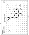
- virtual canvas 12 has been populated with a plurality of selected nodes 32 positioned according to a user's repeated interactions with virtual canvas 12 .
- Each of the plurality of selected nodes 32 represents a corresponding plan object.
- each of the plurality of selected nodes 32 may be individually selected by a user allowing the user to select or otherwise modify one or more parameters for a plan object represented by that node.
- a user has selected a given node causing the display of control 34 through which the user can specify parameters for the represented object.
- the user can select control 35 which, in this example, causes links to be automatically established between the plurality of selected nodes 32 .
- connection 36 between a given pair of nodes represents a link between a corresponding pair of plan objects.
- the links are automatically generated based on connection compatibilities of the plan objects represented by the plurality of selected nodes 32 and the relative positions of the plurality of selected nodes 32 on virtual canvas 12 .
- adjacent nodes, as positioned on grid 14 are linked so long as the connection capabilities of the underlying plan objects are not violated.
- Each connection 36 includes a control 38 with which a user can interact. Interaction with a given control 38 causes the display of a link property control 40 through which the user can specify parameters for a link represented by the corresponding connection 36 .
- the automatically selected links of FIG. 7 may not reflect the links desired by the user.
- the user has selected edit control 41 and swiped a path 42 across virtual canvas 12 .
- the virtual canvas path 42 passes through a user selected set of the plurality of nodes in a desired order. Based on that order and the connection compatibilities of the underlying plan objects, links are created between that set of nodes as depicted visually by connections 44 in FIG. 9 .
- the user can select control 20 to save a plan artifact defining the underlying plan objects, links, and corresponding user selected parameters.
- plan artifact represents a cloud architecture
- the artifact may be used and reused to instantiate that cloud architecture using the components represented by the plan objects and connections represented by the various links between the user selected nodes 32 .
- FIGS. 10 and 11 depict examples of physical and logical components for implementing various embodiments.
- various components are identified as engines 54 - 58 .
- focus is on each engine's designated function.
- the term engine refers to a combination of hardware and programming configured to perform a designated function.
- the hardware of each engine may include a processor and a memory, while the programming is code stored on that memory and executable by the processor to perform the designated function.
- the hardware may be the memory used to store the code.
- FIG. 10 depicts a system 48 for creating a plan artifact.
- System 48 is shown as being in communication with data repository 50 and instantiation service 52 .
- Data repository 50 represents generally any memory for storing electronic data.
- Instantiation service 52 represents generally any combination of hardware and programming configured to process a plan artifact to instantiate the artifact's corresponding design plan.
- System 48 includes interface engine 54 , link engine 56 , and plan engine 58 .
- Interface engine 54 is configured to cause a display of a virtual canvas and a control for selecting from among a plurality of available nodes.
- the nodes may be nodes available to a particular user as defined by data in repository 50 .
- virtual canvas 12 and control 22 are examples of a virtual canvas and control caused to be displayed by engine 54 .
- interface engine 54 is responsible for causing a display of a plurality of user selected nodes positioned on the virtual canvas according to the user's interaction with the control. Plurality of selected nodes 32 depicted in FIG. 6-9 are an example.
- Interface engine 54 may cause the display of the control upon detection of a user interaction with the virtual canvas at a particular location. For example, the user may touch the display at the location or, if using a mouse, click at that location.
- the control in one example, is a pinwheel control having a plurality of node buttons positioned according to the location touched or clicked. That location may, but need not, be a center point for the pin wheel control.
- the node buttons are for selecting from among the plurality of available nodes.
- Interface engine 54 is configured to cause a selected one of the plurality of nodes to be displayed at the center point according to a user interaction with one of the plurality of node buttons.
- interface engine 54 causes the display of the plurality of the nodes selected by the user when interacting with the control at each position.
- Interface engine 54 is also responsible for causing a display of a connection between each pair of nodes identified by link engine 56 as discussed below.
- Link engine 56 is configured to identify links between selected pairs of the displayed nodes based on at least one of a user defined virtual canvas path and relative proximities between the displayed nodes. In performing its function, link engine 56 may generate link data defining the links. The link data may be stored in repository 50 for use by interface engine 50 when causing a display of connections corresponding to the identified links.
- a virtual canvas path is a path over the virtual canvas that passes through two or more of the displayed nodes in a given order.
- Interface engine 54 may be responsible for identifying a user interaction with the virtual canvas that defines the virtual canvas path. For example, the user may swipe or click a path that passes through those nodes. Interface engine 54 may then identify the path as an ordered sequence of nodes such that the links between plan objects may be defined by ink engine 56 at least in part by that sequence.
- FIGS. 8 and 9 illustrate an example
- Link engine 56 may also be configured to examine plan objects associated the plurality of nodes to identify connection compatibilities between the plan objects.
- the plan objects may be stored in or otherwise identified by data stored in repository 50 .
- each available node identified in repository 50 may also identify its corresponding plan object.
- each plan object defines its own connection compatibility, that is, it defines one or more plan objects or object types with which it can link. Linking a plan object to another object that is not identified would, in this example, violate the connection compatibility of the given object.
- link engine 56 may identify links between selected pairs of the displayed nodes based on the identified connection compatibilities and at least one of a user defined virtual canvas path and relative proximities between the displayed nodes.
- Plan engine 58 is configured to create a plan artifact specifying links identified by link engine 56 and objects represented by the displayed nodes.
- Each node and connection caused to be displayed by interface engine 54 may function as a control that when selected allows a user to select parameters. Selecting a given node allows a user to select or otherwise modify node parameters.
- the node parameters are for configuring or otherwise defining an object represented by that node. Selecting a given connection allows a user to select or otherwise modify link parameters.
- the link parameters are for configuring or otherwise defining a link represented by the selected connection.
- plan engine 58 is configured to create a plan artifact specifying links identified by link engine 56 , objects represented by the displayed nodes, and any link or node parameters.
- Plan engine 58 may save the artifact in repository 50 .
- Instantiation service 52 may then process that artifact to instantiate the defined design plan.
- the defined design plan is a cloud architecture
- instantiation service 52 may be a cloud controller or other service capable is instantiating a cloud architecture using the artifact.
- each plan object represented by a displayed node in turn may represent at least one of an infrastructure element, a platform element, an application element, and a service element.
- the plan artifact is then configured to be processed to automatically instantiate at least one of an infrastructure component, platform component, application component, and service component.
- engines 54 - 58 were described as combinations of hardware and programming. Engines 54 - 58 may be implemented in a number of fashions. Looking at FIG. 11 , the programming may be processor executable instructions stored on tangible memory resource 60 and the hardware may include processing resource 62 for executing those instructions. Thus memory resource 60 can be said to store program instructions that when executed by processing resource 62 implement system 48 of FIG. 10 .
- Memory resource 60 represents generally any number of memory components capable of storing instructions that can be executed by processing resource 62 .
- Memory resource 60 is non-transitory in the sense that it does not encompass a transitory signal but instead is made up of more or more memory components configured to store the relevant instructions.
- Memory resource 60 may be implemented in a single device or distributed across devices.
- processing resource 62 represents any number of processors capable of executing instructions stored by memory resource 60 .
- Processing resource 62 may be integrated in a single device or distributed across devices. Further, memory resource 60 may be fully or partially integrated in the same device as processing resource 62 , or it may be separate but accessible to that device and processing resource 62 .
- the program instructions can be part of an installation package that when installed can be executed by processing resource 62 to implement system 48 .
- memory resource 60 may be a portable medium such as a CD, DVD, or flash drive or a memory maintained by a server from which the installation package can be downloaded and installed.
- the program instructions may be part of an application or applications already installed.
- memory resource 60 can include integrated memory such as a hard drive, solid state drive, or the like.
- interface module 64 represents program instructions that when executed cause processing resource 62 to implement interface engine 54 of FIG. 10 .
- Link module 66 represents program instructions that when executed cause the implementation of link engine 56 .
- plan module 68 represents program instructions that when executed cause the implementation of plan engine 58 .
- FIG. 12 is a flow diagram of steps taken to implement a method for creating a plan artifact.
- FIG. 12 reference may be made to the screen views of FIGS. 1-9 and the components depicted in FIGS. 10 and 11 . Such reference is made to provide contextual examples and not to limit the manner in which the method depicted by FIG. 12 may be implemented.
- a virtual canvas is caused to be displayed (step 70 ).
- a plurality of user selected nodes are caused to be displayed at positions on the virtual canvas corresponding to locations of the plurality of user interactions (step 72 ).
- Interface engine 54 of FIG. 10 may be responsible for implementing steps 70 and 72 .
- Virtual canvas 12 of FIG. 1 is an example of a virtual canvas caused to be displayed in step 70 .
- Nodes 32 of FIGS. 6-9 are examples of the plurality of nodes caused to be displayed in step 72 .
- Link data defining links between selected pairs of the displayed nodes is generated (step 74 ).
- the pairs are selected according to one or more of a user defined virtual canvas path and relative proximities of the plurality of user selected nodes as positioned on the virtual canvas.
- the displayed nodes can represent plan objects of varying types.
- Step 74 may also include examining the varying objects or object types to identify connection compatibilities between the represented objects.
- link engine 56 may be responsible for implementing step 74 .
- Link engine 56 may identify the connection compatibilities by examining data in repository 50 defining those objects and object types represented by the displayed nodes.
- the link data defining links between the selected pairs of displayed nodes may be generated based on the identified link compatibilities and one or more of a user defined virtual canvas path and relative proximities of the plurality of user selected nodes as positioned on the virtual canvas.
- the link data is used to cause a display of a connection between each of the selected pairs of the displayed nodes with each connection representing a corresponding link (step 76 ).
- interface engine 52 may be responsible for implementing step 76 .
- Connections 36 and 44 in FIGS. 7 and 9 serve as example of connections caused to be displayed in step 76 .
- Step 72 in an example, can include, for each of the plurality of user interactions with the virtual canvas, causing a display of a pin wheel interface control having a plurality of node buttons positioned around a corresponding center point having a position on the virtual canvas selected by the user. Causing a display of the plurality of user selected nodes can then include, for each corresponding center point, causing a display of a corresponding node at that center point. The corresponding node is selected according to a user's interaction with one of the node buttons positioned around that center point.
- Each displayed node may functions as a control that when selected allows a user to select a parameter for an object represented by that node.
- Each displayed connection may function as a control that when selected allows a user to select a parameter for a link represented by that connection.
- the method depicted in FIG. 12 may also include creating a plan artifact defining the objects represented by the displayed nodes, the links represented by the displayed connections, and corresponding parameters selected by the user. Referring to FIG. 10 , plan engine 58 may be responsible for doing so.
- FIGS. 1-9 depict a user interface used to define a design plan. That user interface is an example only.
- FIGS. 10-11 aid in depicting the architecture, functionality, and operation of various embodiments.
- FIGS. 10 and 11 depict various physical and logical components.
- Various components are defined at least in part as programs or programming. Each such component, portion thereof, or various combinations thereof may represent in whole or in part a module, segment, or portion of code that comprises one or more executable instructions to implement any specified logical function(s).
- Each component or various combinations thereof may represent a circuit or a number of interconnected circuits to implement the specified logical function(s).
- Embodiments can be realized in any memory resource for use by or in connection with processing resource.
- a “processing resource” is an instruction execution system such as a computer/processor based system or an ASIC (Application Specific Integrated Circuit) or other system that can fetch or obtain instructions and data from computer-readable media and execute the instructions contained therein.
- a “memory resource” is any non-transitory storage media that can contain, store, or maintain programs and data for use by or in connection with the instruction execution system. The term “non-transitory is used only to clarify that the term media, as used herein, does not encompass a signal.
- the memory resource can comprise any one of many physical media such as, for example, electronic, magnetic, optical, electromagnetic, or semiconductor media. More specific examples of suitable computer-readable media include, but are not limited to, hard drives, solid state drives, random access memory (RAM), read-only memory (ROM), erasable programmable read-only memory, flash drives, and portable compact discs.
- FIG. 12 shows a specific order of execution, the order of execution may differ from that which is depicted.
- the order of execution of two or more blocks or arrows may be scrambled relative to the order shown.
- two or more blocks shown in succession may be executed concurrently or with partial concurrence. All such variations are within the scope of the present invention.
Landscapes
- Engineering & Computer Science (AREA)
- Software Systems (AREA)
- General Engineering & Computer Science (AREA)
- Theoretical Computer Science (AREA)
- Computer Networks & Wireless Communication (AREA)
- Signal Processing (AREA)
- Physics & Mathematics (AREA)
- General Physics & Mathematics (AREA)
- Human Computer Interaction (AREA)
- User Interface Of Digital Computer (AREA)
- Stored Programmes (AREA)
Abstract
Description
Claims (20)
Applications Claiming Priority (1)
| Application Number | Priority Date | Filing Date | Title |
|---|---|---|---|
| PCT/US2013/028442 WO2014133533A1 (en) | 2013-02-28 | 2013-02-28 | An interface for creating a plan artifact |
Publications (2)
| Publication Number | Publication Date |
|---|---|
| US20150350007A1 US20150350007A1 (en) | 2015-12-03 |
| US10862745B2 true US10862745B2 (en) | 2020-12-08 |
Family
ID=51428650
Family Applications (1)
| Application Number | Title | Priority Date | Filing Date |
|---|---|---|---|
| US14/759,704 Active 2035-01-15 US10862745B2 (en) | 2013-02-28 | 2013-02-28 | Interface for creating a plan artifact |
Country Status (4)
| Country | Link |
|---|---|
| US (1) | US10862745B2 (en) |
| EP (1) | EP2962181A4 (en) |
| CN (1) | CN104969186A (en) |
| WO (1) | WO2014133533A1 (en) |
Families Citing this family (4)
| Publication number | Priority date | Publication date | Assignee | Title |
|---|---|---|---|---|
| US9767197B1 (en) | 2014-08-20 | 2017-09-19 | Vmware, Inc. | Datacenter operations using search and analytics |
| US10567238B1 (en) * | 2014-08-20 | 2020-02-18 | Vmware, Inc. | Server system ring topology user interface system |
| USD828379S1 (en) * | 2016-01-05 | 2018-09-11 | Lg Electronics Inc. | Display screen with graphical user interface |
| CN111831174A (en) * | 2019-04-22 | 2020-10-27 | 阿里巴巴集团控股有限公司 | Event setting method, device, equipment and storage medium |
Citations (18)
| Publication number | Priority date | Publication date | Assignee | Title |
|---|---|---|---|---|
| WO2001054350A2 (en) | 2000-01-21 | 2001-07-26 | Metasolv Software, Inc. | System and method for modeling communication networks |
| WO2001075568A1 (en) | 2000-03-30 | 2001-10-11 | Ideogramic Aps | Method for gesture based modeling |
| EP1679857A1 (en) | 2003-10-30 | 2006-07-12 | Vodafone K.K. | Mobile communication terminal apparatus, core module for mobile communication terminal apparatus, and function module for mobile communication terminal apparatus |
| US7450505B2 (en) * | 2001-06-01 | 2008-11-11 | Fujitsu Limited | System and method for topology constrained routing policy provisioning |
| US7519917B2 (en) | 2006-01-03 | 2009-04-14 | International Business Machines Corporation | Method and apparatus for graphically displaying compatible workflow steps |
| US20100074141A1 (en) * | 2008-09-24 | 2010-03-25 | United States Government As Represented By The Secretary Of The Army | System and Method for Visually Creating, Editing, Manipulating, Verifying, and/or Animating Desired Topologies of a Mobile Ad Hoc Network and/or for Generating Mobility-Pattern Data |
| US20100094598A1 (en) | 2008-10-09 | 2010-04-15 | Kabushiki Kaisha Toshiba | Three-dimensional data generation device, method and program thereof |
| US20110138047A1 (en) | 2009-12-03 | 2011-06-09 | International Business Machines Corporation | Provisioning services using a cloud services catalog |
| US20120131460A1 (en) * | 2010-11-19 | 2012-05-24 | Nokia Corporation | Playlist Creation |
| CN102566916A (en) | 2010-12-17 | 2012-07-11 | 微软公司 | Creation, editing and navigation of diagrams |
| CN102591644A (en) | 2010-12-13 | 2012-07-18 | 微软公司 | Static definition of unknown visual layout positions |
| US20120203908A1 (en) | 2011-02-08 | 2012-08-09 | International Business Machines Corporation | Hybrid cloud integrator plug-in components |
| US20120204169A1 (en) | 2011-02-08 | 2012-08-09 | International Business Machines Corporation | Hybrid cloud integrator |
| US20120209506A1 (en) | 2009-07-31 | 2012-08-16 | Hitachi, Ltd. | Navigation device, program, and display method |
| US20120215919A1 (en) | 2011-02-22 | 2012-08-23 | Intuit Inc. | Multidimensional modeling of software offerings |
| US20120254791A1 (en) * | 2011-03-31 | 2012-10-04 | Apple Inc. | Interactive menu elements in a virtual three-dimensional space |
| US20130016126A1 (en) | 2011-07-12 | 2013-01-17 | Autodesk, Inc. | Drawing aid system for multi-touch devices |
| CN105009055A (en) | 2013-01-31 | 2015-10-28 | 惠普发展公司,有限责任合伙企业 | Defining a design plan |
Family Cites Families (1)
| Publication number | Priority date | Publication date | Assignee | Title |
|---|---|---|---|---|
| US7814427B2 (en) * | 2005-01-05 | 2010-10-12 | Microsoft Corporation | Object model tree diagram |
-
2013
- 2013-02-28 CN CN201380071719.8A patent/CN104969186A/en active Pending
- 2013-02-28 EP EP13876692.8A patent/EP2962181A4/en not_active Withdrawn
- 2013-02-28 WO PCT/US2013/028442 patent/WO2014133533A1/en active Application Filing
- 2013-02-28 US US14/759,704 patent/US10862745B2/en active Active
Patent Citations (19)
| Publication number | Priority date | Publication date | Assignee | Title |
|---|---|---|---|---|
| WO2001054350A2 (en) | 2000-01-21 | 2001-07-26 | Metasolv Software, Inc. | System and method for modeling communication networks |
| WO2001075568A1 (en) | 2000-03-30 | 2001-10-11 | Ideogramic Aps | Method for gesture based modeling |
| US20040060037A1 (en) | 2000-03-30 | 2004-03-25 | Damm Christian Heide | Method for gesture based modeling |
| US7450505B2 (en) * | 2001-06-01 | 2008-11-11 | Fujitsu Limited | System and method for topology constrained routing policy provisioning |
| EP1679857A1 (en) | 2003-10-30 | 2006-07-12 | Vodafone K.K. | Mobile communication terminal apparatus, core module for mobile communication terminal apparatus, and function module for mobile communication terminal apparatus |
| US7519917B2 (en) | 2006-01-03 | 2009-04-14 | International Business Machines Corporation | Method and apparatus for graphically displaying compatible workflow steps |
| US20100074141A1 (en) * | 2008-09-24 | 2010-03-25 | United States Government As Represented By The Secretary Of The Army | System and Method for Visually Creating, Editing, Manipulating, Verifying, and/or Animating Desired Topologies of a Mobile Ad Hoc Network and/or for Generating Mobility-Pattern Data |
| US20100094598A1 (en) | 2008-10-09 | 2010-04-15 | Kabushiki Kaisha Toshiba | Three-dimensional data generation device, method and program thereof |
| US20120209506A1 (en) | 2009-07-31 | 2012-08-16 | Hitachi, Ltd. | Navigation device, program, and display method |
| US20110138047A1 (en) | 2009-12-03 | 2011-06-09 | International Business Machines Corporation | Provisioning services using a cloud services catalog |
| US20120131460A1 (en) * | 2010-11-19 | 2012-05-24 | Nokia Corporation | Playlist Creation |
| CN102591644A (en) | 2010-12-13 | 2012-07-18 | 微软公司 | Static definition of unknown visual layout positions |
| CN102566916A (en) | 2010-12-17 | 2012-07-11 | 微软公司 | Creation, editing and navigation of diagrams |
| US20120203908A1 (en) | 2011-02-08 | 2012-08-09 | International Business Machines Corporation | Hybrid cloud integrator plug-in components |
| US20120204169A1 (en) | 2011-02-08 | 2012-08-09 | International Business Machines Corporation | Hybrid cloud integrator |
| US20120215919A1 (en) | 2011-02-22 | 2012-08-23 | Intuit Inc. | Multidimensional modeling of software offerings |
| US20120254791A1 (en) * | 2011-03-31 | 2012-10-04 | Apple Inc. | Interactive menu elements in a virtual three-dimensional space |
| US20130016126A1 (en) | 2011-07-12 | 2013-01-17 | Autodesk, Inc. | Drawing aid system for multi-touch devices |
| CN105009055A (en) | 2013-01-31 | 2015-10-28 | 惠普发展公司,有限责任合伙企业 | Defining a design plan |
Non-Patent Citations (5)
| Title |
|---|
| Boomi, Inc., "Connect Once, Integrate Everywhere," (Web Page), Copyright 2013, 3 pages, available at http://www.boomi.com/solutions. |
| Extended European Search Report dated Sep. 13, 2016; EP Application No. 13876692.6; Pages 6. |
| International Search Report & Written Opinion received in PCT Application No. PCT/US2013/028442, dated Nov. 25, 2013, 10 pages. |
| U.S. Appl. No. 14/761,550, Non-Final Rejection dated Sep. 15, 2017. pp. 1-12 and attachments. |
| Valant, C., "ITIL and Cloud Series: Service Design for Cloud Implementation," (Web Page), Jan. 3, 2012, 4 pages, available at http://thoughtsoncloud.com/index/php/2012/01/itil-and-cloud-series-service-design-for-cloud-implementation/. |
Also Published As
| Publication number | Publication date |
|---|---|
| WO2014133533A1 (en) | 2014-09-04 |
| EP2962181A4 (en) | 2016-10-12 |
| CN104969186A (en) | 2015-10-07 |
| EP2962181A1 (en) | 2016-01-06 |
| US20150350007A1 (en) | 2015-12-03 |
Similar Documents
| Publication | Publication Date | Title |
|---|---|---|
| US9621428B1 (en) | Multi-tiered cloud application topology modeling tool | |
| US20190392617A1 (en) | Visual workflow model | |
| US20210034336A1 (en) | Executing a process-based software application in a first computing environment and a second computing environment | |
| US7577937B2 (en) | Methods and systems for generating a configurable user interface | |
| CN111078315A (en) | Microservice arranging and executing method and system, architecture, equipment and storage medium | |
| US11238386B2 (en) | Task derivation for workflows | |
| Blouin et al. | Combining aspect-oriented modeling with property-based reasoning to improve user interface adaptation | |
| US20130332873A1 (en) | Health Information Mapping System With Graphical Editor | |
| JP2015504186A (en) | System and method for mobile application development | |
| Kolb et al. | Using concurrent task trees for stakeholder-centered modeling and visualization of business processes | |
| US10142188B2 (en) | System and method for providing guiding messages in creating an integration flow in a cloud-based integration platform | |
| US10862745B2 (en) | Interface for creating a plan artifact | |
| US11714625B2 (en) | Generating applications for versatile platform deployment | |
| CN107203465A (en) | System interface method of testing and device | |
| US20100162208A1 (en) | Modeling tool builder - graphical editor construction | |
| CN112464497B (en) | Fault drilling method, device, equipment and medium based on distributed system | |
| EP3413149B1 (en) | Field device commissioning system and field device commissioning method | |
| US10628287B2 (en) | Identification and handling of nested breakpoints during debug session | |
| US20220343901A1 (en) | Systems and methods of implementing platforms for bot interfaces within an intelligent development platform | |
| US20110066566A1 (en) | Conceptual representation of business processes for cross-domain mapping | |
| US20230267255A1 (en) | Semiconductor equipment modeling method and device | |
| CN116569141A (en) | Workflow repair | |
| US10042638B2 (en) | Evaluating documentation coverage | |
| US20150363096A1 (en) | Defining a design plan | |
| US20100250228A1 (en) | Modeling a composite application |
Legal Events
| Date | Code | Title | Description |
|---|---|---|---|
| AS | Assignment |
Owner name: HEWLETT-PACKARD DEVELOPMENT COMPANY, L.P., TEXAS Free format text: ASSIGNMENT OF ASSIGNORS INTEREST;ASSIGNOR:CARLOZZI, CHRISTOPHER MICHAEL;REEL/FRAME:036225/0400 Effective date: 20140224 |
|
| AS | Assignment |
Owner name: HEWLETT PACKARD ENTERPRISE DEVELOPMENT LP, TEXAS Free format text: ASSIGNMENT OF ASSIGNORS INTEREST;ASSIGNOR:HEWLETT-PACKARD DEVELOPMENT COMPANY, L.P.;REEL/FRAME:037079/0001 Effective date: 20151027 |
|
| AS | Assignment |
Owner name: ENTIT SOFTWARE LLC, CALIFORNIA Free format text: ASSIGNMENT OF ASSIGNORS INTEREST;ASSIGNOR:HEWLETT PACKARD ENTERPRISE DEVELOPMENT LP;REEL/FRAME:042746/0130 Effective date: 20170405 |
|
| AS | Assignment |
Owner name: JPMORGAN CHASE BANK, N.A., DELAWARE Free format text: SECURITY INTEREST;ASSIGNORS:ATTACHMATE CORPORATION;BORLAND SOFTWARE CORPORATION;NETIQ CORPORATION;AND OTHERS;REEL/FRAME:044183/0718 Effective date: 20170901 Owner name: JPMORGAN CHASE BANK, N.A., DELAWARE Free format text: SECURITY INTEREST;ASSIGNORS:ENTIT SOFTWARE LLC;ARCSIGHT, LLC;REEL/FRAME:044183/0577 Effective date: 20170901 |
|
| STCV | Information on status: appeal procedure |
Free format text: ON APPEAL -- AWAITING DECISION BY THE BOARD OF APPEALS |
|
| AS | Assignment |
Owner name: MICRO FOCUS LLC, CALIFORNIA Free format text: CHANGE OF NAME;ASSIGNOR:ENTIT SOFTWARE LLC;REEL/FRAME:050004/0001 Effective date: 20190523 |
|
| STCV | Information on status: appeal procedure |
Free format text: BOARD OF APPEALS DECISION RENDERED |
|
| STPP | Information on status: patent application and granting procedure in general |
Free format text: DOCKETED NEW CASE - READY FOR EXAMINATION |
|
| STPP | Information on status: patent application and granting procedure in general |
Free format text: NOTICE OF ALLOWANCE MAILED -- APPLICATION RECEIVED IN OFFICE OF PUBLICATIONS |
|
| STCF | Information on status: patent grant |
Free format text: PATENTED CASE |
|
| AS | Assignment |
Owner name: MICRO FOCUS LLC (F/K/A ENTIT SOFTWARE LLC), CALIFORNIA Free format text: RELEASE OF SECURITY INTEREST REEL/FRAME 044183/0577;ASSIGNOR:JPMORGAN CHASE BANK, N.A.;REEL/FRAME:063560/0001 Effective date: 20230131 Owner name: NETIQ CORPORATION, WASHINGTON Free format text: RELEASE OF SECURITY INTEREST REEL/FRAME 044183/0718;ASSIGNOR:JPMORGAN CHASE BANK, N.A.;REEL/FRAME:062746/0399 Effective date: 20230131 Owner name: MICRO FOCUS SOFTWARE INC. (F/K/A NOVELL, INC.), WASHINGTON Free format text: RELEASE OF SECURITY INTEREST REEL/FRAME 044183/0718;ASSIGNOR:JPMORGAN CHASE BANK, N.A.;REEL/FRAME:062746/0399 Effective date: 20230131 Owner name: ATTACHMATE CORPORATION, WASHINGTON Free format text: RELEASE OF SECURITY INTEREST REEL/FRAME 044183/0718;ASSIGNOR:JPMORGAN CHASE BANK, N.A.;REEL/FRAME:062746/0399 Effective date: 20230131 Owner name: SERENA SOFTWARE, INC, CALIFORNIA Free format text: RELEASE OF SECURITY INTEREST REEL/FRAME 044183/0718;ASSIGNOR:JPMORGAN CHASE BANK, N.A.;REEL/FRAME:062746/0399 Effective date: 20230131 Owner name: MICRO FOCUS (US), INC., MARYLAND Free format text: RELEASE OF SECURITY INTEREST REEL/FRAME 044183/0718;ASSIGNOR:JPMORGAN CHASE BANK, N.A.;REEL/FRAME:062746/0399 Effective date: 20230131 Owner name: BORLAND SOFTWARE CORPORATION, MARYLAND Free format text: RELEASE OF SECURITY INTEREST REEL/FRAME 044183/0718;ASSIGNOR:JPMORGAN CHASE BANK, N.A.;REEL/FRAME:062746/0399 Effective date: 20230131 Owner name: MICRO FOCUS LLC (F/K/A ENTIT SOFTWARE LLC), CALIFORNIA Free format text: RELEASE OF SECURITY INTEREST REEL/FRAME 044183/0718;ASSIGNOR:JPMORGAN CHASE BANK, N.A.;REEL/FRAME:062746/0399 Effective date: 20230131 |
|
| MAFP | Maintenance fee payment |
Free format text: PAYMENT OF MAINTENANCE FEE, 4TH YEAR, LARGE ENTITY (ORIGINAL EVENT CODE: M1551); ENTITY STATUS OF PATENT OWNER: LARGE ENTITY Year of fee payment: 4 |