US10862175B2 - Battery fuel gauge circuit - Google Patents
Battery fuel gauge circuit Download PDFInfo
- Publication number
- US10862175B2 US10862175B2 US15/989,415 US201815989415A US10862175B2 US 10862175 B2 US10862175 B2 US 10862175B2 US 201815989415 A US201815989415 A US 201815989415A US 10862175 B2 US10862175 B2 US 10862175B2
- Authority
- US
- United States
- Prior art keywords
- battery
- converter
- power supply
- fuel gauge
- logic circuit
- Prior art date
- Legal status (The legal status is an assumption and is not a legal conclusion. Google has not performed a legal analysis and makes no representation as to the accuracy of the status listed.)
- Active, expires
Links
Images


Classifications
-
- H—ELECTRICITY
- H01—ELECTRIC ELEMENTS
- H01M—PROCESSES OR MEANS, e.g. BATTERIES, FOR THE DIRECT CONVERSION OF CHEMICAL ENERGY INTO ELECTRICAL ENERGY
- H01M10/00—Secondary cells; Manufacture thereof
- H01M10/42—Methods or arrangements for servicing or maintenance of secondary cells or secondary half-cells
- H01M10/4285—Testing apparatus
-
- H—ELECTRICITY
- H01—ELECTRIC ELEMENTS
- H01M—PROCESSES OR MEANS, e.g. BATTERIES, FOR THE DIRECT CONVERSION OF CHEMICAL ENERGY INTO ELECTRICAL ENERGY
- H01M10/00—Secondary cells; Manufacture thereof
- H01M10/42—Methods or arrangements for servicing or maintenance of secondary cells or secondary half-cells
- H01M10/425—Structural combination with electronic components, e.g. electronic circuits integrated to the outside of the casing
- H01M2010/4271—Battery management systems including electronic circuits, e.g. control of current or voltage to keep battery in healthy state, cell balancing
-
- Y—GENERAL TAGGING OF NEW TECHNOLOGICAL DEVELOPMENTS; GENERAL TAGGING OF CROSS-SECTIONAL TECHNOLOGIES SPANNING OVER SEVERAL SECTIONS OF THE IPC; TECHNICAL SUBJECTS COVERED BY FORMER USPC CROSS-REFERENCE ART COLLECTIONS [XRACs] AND DIGESTS
- Y02—TECHNOLOGIES OR APPLICATIONS FOR MITIGATION OR ADAPTATION AGAINST CLIMATE CHANGE
- Y02E—REDUCTION OF GREENHOUSE GAS [GHG] EMISSIONS, RELATED TO ENERGY GENERATION, TRANSMISSION OR DISTRIBUTION
- Y02E60/00—Enabling technologies; Technologies with a potential or indirect contribution to GHG emissions mitigation
- Y02E60/10—Energy storage using batteries
Definitions
- the present invention relates to a battery management system.
- Various kinds of battery-driven electronic devices such as cellular phone terminals, digital still cameras, tablet terminals, portable music players, portable game machines, and laptop computers include a built-in chargeable battery (secondary battery).
- Electronic circuits such as a CPU (Central Processing Unit) adapted to system control operation and signal processing, a liquid crystal panel, a wireless communication module, and other kinds of analog circuits and digital circuits, each operate receiving power supplied from the battery.
- CPU Central Processing Unit
- FIG. 1 is a block diagram showing a battery-driven electronic device.
- An electronic device 500 includes a battery 502 and a charger circuit 504 that charges the battery 502 .
- the battery 502 is configured as a rechargeable secondary battery.
- the charger circuit 504 receives a power supply voltage V ADP from an external power supply adapter or USB (Universal Serial Bus), and charges the battery 502 .
- V ADP power supply voltage
- USB Universal Serial Bus
- the battery 502 is coupled to a load 508 .
- a current I BAT that flows through the battery 502 is configured as a difference between a charging current I CHG supplied from the charger circuit 504 and a load current (discharging current) I LOAD that flows through the load 508 .
- Such a battery-driven electronic device has a function of detecting the remaining battery charge (state of charge: SOC) as an indispensable function.
- the electronic device 500 is provided with a battery fuel gauge circuit 506 .
- the battery fuel gauge circuit 506 is also referred to as a “fuel gauge IC (Integrated Circuit)”.
- As a detection method for detecting the remaining battery charge provided by the battery fuel gauge circuit 506 two methods, i.e., (1) the voltage method and (2) the coulomb counting method (charge integration method), have become mainstream. In many cases, a combination of them is employed. In some cases, the battery fuel gauge circuit 506 is built into the charger circuit 504 .
- the open circuit voltage (OCV) of the battery is measured in an open circuit state (no-load state).
- the remaining battery charge is estimated based on the correspondence between the OCV and the SOC.
- the measurement of OCV requires the battery to be in a no-load state and in a relaxed state. Accordingly, the OCV cannot be measured with sufficient precision when the battery is charged or discharged.
- the charging current that flows into the battery and the discharging current that flows from the battery are integrated, so as to calculate the amount of charge supplied to the battery and the amount of charge discharged from the battery, thereby estimating the remaining battery charge.
- the coulomb counting method unlike the voltage method, the remaining battery charge can be estimated even in a period in which the battery is used and the open circuit voltage cannot be acquired.
- this method requires information with respect to the remaining battery charge (initial remaining battery charge) before the battery is charged or discharged.
- the initial remaining battery charge is detected using the voltage method, which requires measurement of the OCV.
- a battery fuel gauge circuit 506 measures the OCV, and holds the measurement value in a register.
- the initial value of the SOC (initial SOC) is estimated based on the voltage method using the OCV stored in the register. Subsequently, the SOC is updated based on the coulomb counting method.
- the present invention has been made in order to solve such a problem. Accordingly, it is an exemplary purpose of an embodiment of the present invention to provide a battery fuel gauge circuit that is capable of detecting the initial remaining battery charge with high precision.
- An embodiment of the present invention relates to a battery fuel gauge circuit to be coupled to a battery.
- the battery fuel gauge circuit comprises: a first A/D converter structured to sample a voltage of the battery; and a logic circuit coupled to receive an output of the first A/D converter.
- the logic circuit acquires the output of the first A/D converter when a power supply for a device mounting the battery fuel gauge circuit is turned on for the first time.
- this arrangement is capable of acquiring the initial remaining battery charge with high precision.
- the first A/D converter may sample the voltage of the battery for every predetermined sampling period.
- the logic circuit may acquire the voltage of the battery sampled immediately before or otherwise immediately after the first-time turning-on.
- the first A/D converter may sample the voltage of the battery for every predetermined sampling period. Also, when the power supply for the device is turned on for the first time, the logic circuit may acquire an average value of the multiple voltage values of the battery sampled immediately before the first-time turning-on of the power supply. By calculating the average value, this arrangement is capable of reducing the effects of noise or the like.
- the sampling operation of the first A/D converter for every sampling period may be suspended.
- sampling period may be set within a range from 2 ms to 50 ms.
- the battery fuel gauge circuit may further comprise a second A/D converter structured to sample a current of the battery. Also, the logic circuit may integrate an output of the second A/D converter.
- the logic circuit may be coupled to a processor via an interface. Also, the logic circuit may be capable of transmitting the voltage value of the battery sampled by the first A/D converter and an integrated value of the output of the second A/D converter to the processor.
- the electronic device may comprise: a power supply button; a battery; and any one of the aforementioned battery fuel gauge circuits each structured to monitor a state of the battery.
- FIG. 1 is a block diagram showing a battery-driven electronic device
- FIG. 2 is a block diagram showing an electronic device including a battery fuel gauge circuit according to an embodiment
- FIG. 3 is a diagram for explaining the measurement of the initial OCV performed by the battery fuel gauge circuit shown in FIG. 2 ;
- FIG. 4 is a flowchart for explaining the operation of the electronic device shown in FIG. 2 ;
- FIG. 5 is a diagram for explaining the measurement of the initial OCV according to a modification 1;
- FIG. 6 is a flowchart for explaining the operation of the electronic device according to the modification 1;
- FIG. 7 is a diagram for explaining the measurement of the initial OCV according to a modification 2;
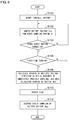
- FIG. 8 is a flowchart for explaining the operation of the electronic device according to the modification 2.
- the state represented by the phrase “the member A is coupled to the member B” includes a state in which the member A is indirectly coupled to the member B via another member that does not substantially affect the electric connection between them, or that does not damage the functions or effects of the connection between them, in addition to a state in which they are physically and directly coupled.
- the state represented by the phrase “the member C is provided between the member A and the member B” includes a state in which the member A is indirectly coupled to the member C, or the member B is indirectly coupled to the member C via another member that does not substantially affect the electric connection between them, or that does not damage the functions or effects of the connection between them, in addition to a state in which they are directly coupled.
- the reference symbols denoting a voltage signal, current signal, or resistor also represent the corresponding voltage value, current value, or resistance value.
- FIG. 2 is a block diagram showing an electronic device 100 including a battery fuel gauge circuit 200 according to an embodiment.
- Examples of such a battery-driven electronic device 100 include a smartphone, tablet terminal, digital still camera, digital video camera, portable audio player, laptop computer, etc.
- the battery-driven electronic device 100 is not restricted to such arrangements.
- the electronic device 100 includes a battery 102 , a charger circuit 104 , a CPU (Central Processing Unit) 106 , a power supply button 108 , and a battery fuel gauge circuit 200 .
- the battery 102 includes one or multiple cells 103 .
- the kind of the cells 103 is not restricted in particular, and examples thereof include lithium-ion cells, lithium-air cells, lithium metal-based cells, nickel-metal hydride cells, nickel-cadmium cells, nickel-zinc cells, etc.
- the number of the cells 103 depends on the usage of the electronic device 100 .
- the battery 102 In a case in which the electronic device 100 is configured as a portable electronic device, the battery 102 is designed to have one to several cells 103 .
- the number of the cells 103 is designed to be on the order of several dozen to several hundred.
- the configuration of the battery 102 is not restricted in particular.
- the charger circuit 104 receives a power supply voltage V EXT from a DC power supply such as an external power supply adapter, USB (Universal Serial Bus), or the like, and charges the battery 102 .
- the CPU 106 is one of the typical loads of the battery 102 .
- the CPU 106 controls the overall operation of the electronic device 100 .
- the power supply button 108 is provided in order to allow the electronic device 100 to be turned on and off.
- the battery fuel gauge circuit 200 acquires information required to detect the state of charge (SOC) of the battery 102 .
- the battery fuel gauge circuit 200 includes a first A/D converter 202 , a second A/D converter 204 , a logic circuit 210 , an interface circuit 220 , and a DC/DC converter 230 , and is configured as a function IC integrated on a single semiconductor substrate.
- the first A/D converter 202 samples (i.e., A/D converts) the voltage V BAT of the battery 102 .
- the first A/D converter 202 may be configured as a successive approximation (SAR) A/D converter.
- the second A/D converter 204 samples the current I BAT of the battery 102 .
- the second A/D converter 204 may be configured as a delta-sigma A/D converter.
- the current I BAT includes the charging current and the discharging current.
- the battery 102 includes the cell 103 and a sensing resistor R S coupled in series.
- the second A/D converter 204 detects the battery current I BAT based on a voltage drop that occurs across the sensing resistor R S .
- the logic circuit 210 is a controller for the battery fuel gauge circuit 200 .
- the logic circuit 210 receives the output (digital voltage detection value D V ) of the first A/D converter 202 and the output (digital current detection value D I ) of the second A/D converter 204 .
- the interface circuit 220 is provided in order to transmit data from the logic circuit 210 to the CPU 106 , and to receive data and instructions from the CPU 106 .
- an I 2 C (Inter IC) interface may be employed as the interface circuit 220 .
- the DC/DC converter 230 receives the battery voltage V BAT , and steps down the battery voltage V BAT thus received, so as to generate a power supply voltage V DD .
- the power supply voltage V DD is supplied to the CPU 106 .
- unshown inductors and smoothing capacitors, which are components of the DC/DC converter 230 are configured as external components of the battery fuel gauge circuit 200 .
- a relaxed state judgment unit 212 of the logic circuit 210 judges that the battery 102 is in a relaxed state.
- An OCV acquisition unit 214 acquires the voltage detection value D V measured in the relaxed state as the OCV of the battery 102 . The OCV value thus measured is used to estimate the SOC based on the voltage method.
- the logic circuit 210 includes a coulomb counting processing unit 216 .
- the coulomb counting processing unit 216 monitors the battery current I BAT , and integrates the current value D I with the current (discharging current) I BAT that flows from the battery 102 as a positive current and with the current (charging current) I BAT that flows into the battery 502 as a negative current, so as to generate an accumulation coulomb count (ACC).
- ⁇ t is set to a constant.
- the coulomb counting processing unit 216 may calculate the charge coulomb count value (CCC value) which is an integrated value of the charging current I CHG and the discharge coulomb count value (DCC value) which is an integrated value of the discharging current I DIS .
- CCC value charge coulomb count value
- DCC value discharge coulomb count value
- a power supply button monitoring unit 218 of the logic circuit 210 is coupled to the power supply button 108 , and monitors whether or not the power supply button 108 is pressed by the user of the electronic device 100 .
- the logic circuit 210 asserts (e.g., sets to the high level) an enable signal EN, and starts up the DC/DC converter 230 .
- the power supply voltage V DD is supplied to the CPU 106 .
- the electronic device 100 is started up according to the control operation of the CPU 106 .
- the power supply button monitoring unit 218 manages a flag FLG that indicates whether or not the pressing thus detected is the first-time pressing.
- the flag FLG is recorded in an internal component of the battery fuel gauge circuit 200 or otherwise in an external component thereof in a non-volatile manner.
- the flag FLG is set to an initial value (e.g., zero).
- the power supply button monitoring unit 218 sets the value of the flag FLG to a value (e.g., 1) that differs from the initial value.
- the OCV to be used as a reference to estimate the SOC based on the voltage method for the first time after the electronic device 100 is shipped will be referred to as the “initial OCV”.
- the logic circuit 210 acquires the output D V of the first A/D converter 202 as the initial OCV.
- the OCV acquisition unit 214 monitors the flag FLG Upon detecting the turning-on of the power supply button 108 when the flag FLG indicates the initial value (0), the OCV acquisition unit 214 acquires the output D V of the first A/D converter 202 .
- the above is the function of the logic circuit 210 .
- the normal OCV value, the initial OCV value, the ACC value, the CCC value, and the DCC value acquired by the logic circuit 210 are transmitted to the CPU 106 via the interface circuit 220 . It should be noted that “are transmitted” includes an operation in which the CPU 106 reads out data stored in memory (a register) included in the battery fuel gauge circuit 200 .
- the CPU 106 executes a software program, and estimates and calculates the SOC based on the voltage method and the coulomb counting method.
- FIG. 3 is a diagram for explaining the operation of the battery fuel gauge circuit 200 shown in FIG. 2 for measuring the initial OCV.
- the battery voltage V BAT is supplied to the battery fuel gauge circuit 200 .
- the battery fuel gauge circuit 200 becomes operable.
- the electronic device 100 is shipped in a state in which the power supply is turned off.
- the flag FLG is initialized.
- the first A/D converter 202 continuously samples the battery voltage V BAT for every predetermined sampling period T S (automatic sampling).
- the sampling period T S is preferably set to several ms to several dozen ms, e.g., 2 ms to 50 ms.
- the sampling period T S can be further lengthened depending on the battery capacity and leak current of the electronic device.
- the sampling period T S may be lengthened up to a period on the order of one hour.
- the sampling period T S may be designed with a period that does not involve an increase in the circuit current due to the intermittent operation of the first A/D converter 202 as the lower limit, and with a period that does not involve a significant change in the remaining battery charge due to the leak current as the upper limit.
- the power supply button monitoring unit 218 monitors the power supply button 108 , and monitors whether or not the power supply has been turned on.
- the power supply button 108 is pressed at the time point t 1 .
- a PWR_ON signal is asserted (e.g., set to the low level).
- the power supply button monitoring unit 218 instructs the OCV acquisition unit 214 to acquire the voltage detection value D V immediately before the assertion.
- the battery fuel gauge circuit 200 (only the first A/D converter 202 and the power supply button monitoring unit 218 ) performs an intermittent operation. Accordingly, the battery current I BAT can be regarded as substantially zero.
- the battery 102 can be assumed to be in the relaxed state. That is to say, the voltage detection value D V thus acquired in this stage is used as the initial OCV value. Subsequently, the value of the flag FLG is changed.
- the automatic sampling operation of the first A/D converter 202 with the sampling period T S is preferably suspended after the power supply is turned on for the first time. This allows unnecessary power consumption to be reduced.
- the DC/DC converter 230 starts up in response to the turning-on of the power supply. In this stage, the power supply voltage V DD is supplied to the CPU 106 , which enables the CPU 106 to operate.
- the CPU 106 receives the initial OCV value from the battery fuel gauge circuit 200 .
- the CPU 106 estimates the initial SOC that corresponds to the initial OCV value based on a table or an expression that defines the correspondence between the OCV and the SOC.
- the battery current I BAT having a non-zero value flows from the battery 102 , i.e., the battery becomes the non-relaxed state.
- the second A/D converter 204 and the coulomb counting processing unit 216 each become active. In this state, the coulomb count values ACC, CCC and DCC are calculated.
- the CPU 106 updates the SOC by calculation based on the initial SOC and the coulomb count value ACC.
- FIG. 4 is a flowchart for explaining the operation of the electronic device 100 shown in FIG. 2 . It should be noted that, in the flowchart, the order of each step may be exchanged as appropriate so long as no problem occurs. Also, multiple steps may be executed in parallel.
- the battery 102 is mounted (or otherwise installed) (S 100 ). This enables the battery fuel gauge circuit 200 to operate.
- the first A/D converter 202 starts sampling of the battery voltage V BAT (S 102 ).
- Whether or not the power supply button 108 has been pressed is monitored (S 104 ).
- the pressing of the power supply button 108 has not been detected (NO in S 104 )
- the sampling of the battery V BAT is maintained.
- the voltage detection value D V acquired in the immediately previous sampling is held as the initial OCV (S 108 ).
- the flag FLG that indicates whether or not the power supply has been turned on for the first time is changed (S 110 ), and the cyclic sampling operation of the first A/D converter 202 is suspended.
- the OCV measurement is performed based on the normal resting time.
- the above is the operation of the battery fuel gauge circuit 200 and the electronic device 100 .
- this arrangement is capable of acquiring the initial OCV with high precision, thereby detecting the initial remaining battery charge (initial SOC) with high precision.
- FIG. 5 is a diagram for explaining the measurement of the initial OCV according to a modification 1.
- an average of multiple voltage detection values D V measured immediately before the time point t 1 may be used as the initial OCV.
- simple average calculation or weighted average calculation may be employed.
- moving average calculation may be employed.
- the voltage detection values D V to be used for the average calculation may be measured in a time-based series.
- such data to be used for the average calculation may be extracted for every N (N ⁇ 2) data items.
- FIG. 6 is a flowchart for explaining the operation of the electronic device 100 according to the modification 1.
- the step S 108 shown in FIG. 4 is amended to step S 109 .
- the average value of the multiple voltage detection values D V acquired in the immediately previous sampling is held as the initial OCV (S 109 ).
- the output of the A/D converter fluctuates due to the effect of noise, leading to a problem in that the voltage detection value cannot be acquired with high precision.
- this arrangement is capable of reducing the effect of noise.
- the average processing may be performed after judgment has been made that the power supply has been turned on for the first time.
- the average value may be updated every time the battery voltage V BAT is sampled in step S 102 .
- FIG. 7 is a diagram for explaining the measurement of the initial OCV according to a modification 2.
- the voltage detection value D V measured immediately after the time point t 1 may be used as the initial OCV.
- FIG. 8 is a flowchart for explaining the operation of the electronic device 100 according to the modification 2.
- the battery voltage V BAT is sampled once more (S 103 ).
- the voltage detection value D V thus acquired in the last sampling (S 103 ) is held as the initial OCV (S 108 ).
- the DC/DC converter 230 may be integrated on another power management IC (PMIC) that differs from the battery fuel gauge circuit 200 .
- PMIC power management IC
Landscapes
- Engineering & Computer Science (AREA)
- Manufacturing & Machinery (AREA)
- Chemical & Material Sciences (AREA)
- Chemical Kinetics & Catalysis (AREA)
- Electrochemistry (AREA)
- General Chemical & Material Sciences (AREA)
- Microelectronics & Electronic Packaging (AREA)
- Secondary Cells (AREA)
- Tests Of Electric Status Of Batteries (AREA)
- Charge And Discharge Circuits For Batteries Or The Like (AREA)
Abstract
Description
ACC=Σi=1(Δt×I BATi)
Claims (7)
Applications Claiming Priority (4)
| Application Number | Priority Date | Filing Date | Title |
|---|---|---|---|
| JP2017-105482 | 2017-05-29 | ||
| JP2017105482 | 2017-05-29 | ||
| JP2018-085778 | 2018-04-26 | ||
| JP2018085778A JP7141236B2 (en) | 2017-05-29 | 2018-04-26 | BATTERY LEVEL DETECTION CIRCUIT, ELECTRONIC DEVICE USING THE SAME, BATTERY LEVEL DETECTION METHOD |
Publications (2)
| Publication Number | Publication Date |
|---|---|
| US20180342774A1 US20180342774A1 (en) | 2018-11-29 |
| US10862175B2 true US10862175B2 (en) | 2020-12-08 |
Family
ID=64401863
Family Applications (1)
| Application Number | Title | Priority Date | Filing Date |
|---|---|---|---|
| US15/989,415 Active 2038-07-04 US10862175B2 (en) | 2017-05-29 | 2018-05-25 | Battery fuel gauge circuit |
Country Status (1)
| Country | Link |
|---|---|
| US (1) | US10862175B2 (en) |
Families Citing this family (4)
| Publication number | Priority date | Publication date | Assignee | Title |
|---|---|---|---|---|
| CA3037161C (en) * | 2018-03-20 | 2022-11-22 | Steffes Corporation | Flow-based energy management |
| CN109884543B (en) * | 2019-01-25 | 2021-12-14 | 努比亚技术有限公司 | Method and equipment for predicting remaining service life of battery |
| JP7092307B2 (en) | 2019-02-01 | 2022-06-28 | 三菱電機株式会社 | Work discrimination device and work discrimination method |
| US11901751B2 (en) * | 2021-01-22 | 2024-02-13 | Google Llc | Systems and methods for monitoring high charge levels in rechargeable batteries |
Citations (9)
| Publication number | Priority date | Publication date | Assignee | Title |
|---|---|---|---|---|
| CN1292512A (en) | 1999-10-08 | 2001-04-25 | Lg电子株式会社 | Flat-plate type monitor |
| JP2002304940A (en) | 2001-04-04 | 2002-10-18 | Denso Corp | Electric contact structure |
| JP2004304940A (en) | 2003-03-31 | 2004-10-28 | Fujitsu Ltd | Battery pack, electronic apparatus, battery remaining capacity prediction system, and semiconductor device |
| US20050007068A1 (en) * | 2002-11-22 | 2005-01-13 | Johnson Todd W. | Method and system for battery protection |
| CN1292527C (en) | 2002-10-11 | 2006-12-27 | 佳能株式会社 | Detecting method and detecting apparatus for detecting internal resistance of a rechargeable battery and rechargeable battery pack having said detecting apparatus therein |
| US20090278701A1 (en) * | 2008-05-08 | 2009-11-12 | Echostar Technologies L.L.C. | Systems, methods and apparatus for detecting replacement of a battery in a remote control |
| US20120306450A1 (en) * | 2011-05-30 | 2012-12-06 | Renesas Electronics Corporation | Semiconductor Integrated Circuit Having Battery Control Function and Operation Method Thereof |
| US20150115971A1 (en) * | 2013-10-24 | 2015-04-30 | Samsung Electronics Co., Ltd. | Electronic apparatus, input apparatus for display apparatus, and method of detecting remaining utility of battery of the same |
| US20160124051A1 (en) * | 2014-10-29 | 2016-05-05 | Texas Instruments Incorporated | Battery fuel gauge |
-
2018
- 2018-05-25 US US15/989,415 patent/US10862175B2/en active Active
Patent Citations (9)
| Publication number | Priority date | Publication date | Assignee | Title |
|---|---|---|---|---|
| CN1292512A (en) | 1999-10-08 | 2001-04-25 | Lg电子株式会社 | Flat-plate type monitor |
| JP2002304940A (en) | 2001-04-04 | 2002-10-18 | Denso Corp | Electric contact structure |
| CN1292527C (en) | 2002-10-11 | 2006-12-27 | 佳能株式会社 | Detecting method and detecting apparatus for detecting internal resistance of a rechargeable battery and rechargeable battery pack having said detecting apparatus therein |
| US20050007068A1 (en) * | 2002-11-22 | 2005-01-13 | Johnson Todd W. | Method and system for battery protection |
| JP2004304940A (en) | 2003-03-31 | 2004-10-28 | Fujitsu Ltd | Battery pack, electronic apparatus, battery remaining capacity prediction system, and semiconductor device |
| US20090278701A1 (en) * | 2008-05-08 | 2009-11-12 | Echostar Technologies L.L.C. | Systems, methods and apparatus for detecting replacement of a battery in a remote control |
| US20120306450A1 (en) * | 2011-05-30 | 2012-12-06 | Renesas Electronics Corporation | Semiconductor Integrated Circuit Having Battery Control Function and Operation Method Thereof |
| US20150115971A1 (en) * | 2013-10-24 | 2015-04-30 | Samsung Electronics Co., Ltd. | Electronic apparatus, input apparatus for display apparatus, and method of detecting remaining utility of battery of the same |
| US20160124051A1 (en) * | 2014-10-29 | 2016-05-05 | Texas Instruments Incorporated | Battery fuel gauge |
Non-Patent Citations (3)
| Title |
|---|
| JP410177457 (Year: 1998). * |
| Taiwanese Notice of Allowance issued for corresponding Application No. 107118254. Dated Feb. 27, 2019. |
| Taiwanese Office Action corresponding to Application No. 107118254; Dated Nov. 14, 2019. |
Also Published As
| Publication number | Publication date |
|---|---|
| US20180342774A1 (en) | 2018-11-29 |
Similar Documents
| Publication | Publication Date | Title |
|---|---|---|
| US10862175B2 (en) | Battery fuel gauge circuit | |
| US9869724B2 (en) | Power management system | |
| US10191118B2 (en) | Battery DC impedance measurement | |
| US10802078B2 (en) | Current monitoring circuit and coulomb counter circuit | |
| US10408887B2 (en) | Method for estimating degradation of rechargeable battery, degradation estimation circuit, electronic apparatus and vehicle including same | |
| US8749204B2 (en) | Battery condition detector, battery pack including same, and battery condition detecting method | |
| US7683580B2 (en) | Remaining-battery-capacity estimating apparatus, remaining-battery-capacity estimating method, and remaining-battery-capacity estimating computer program | |
| US20110234167A1 (en) | Method of Predicting Remaining Capacity and Run-time of a Battery Device | |
| TWI639015B (en) | Residual battery detection circuit, electronic device using the same, automobile and charging state detection method | |
| US20140306712A1 (en) | Tracking aging effect on battery impedance and tracking battery state of health | |
| EP2893608B1 (en) | Method and system for voltage collapse protection | |
| KR100490393B1 (en) | System and method for automatic notification of battery replacement time | |
| US9077197B2 (en) | Battery residual amount measurement system, computer-readable medium storing battery residual amount measurement program, and battery residual amount measurement method | |
| TWI439714B (en) | Battery voltage measurement | |
| KR100781792B1 (en) | The intergrated circuit to measure the remaining capacity | |
| JP7141236B2 (en) | BATTERY LEVEL DETECTION CIRCUIT, ELECTRONIC DEVICE USING THE SAME, BATTERY LEVEL DETECTION METHOD | |
| CN102033204A (en) | Battery power detection circuit, method and electronic system | |
| KR101175369B1 (en) | Apparatus and Methode of measuring charges in a battery | |
| JP2015025686A (en) | Secondary battery pack management method, power source management system, and electronic device | |
| CN111551867B (en) | Battery service life detection method and device, and battery replacement reminding method and device | |
| KR100512165B1 (en) | A method for calibrating a capacity of battery | |
| CN117129884A (en) | Measuring circuit, measuring method, measuring device, electronic apparatus, and storage medium | |
| JP2004279145A (en) | Semiconductor device for measuring secondary battery capacity |
Legal Events
| Date | Code | Title | Description |
|---|---|---|---|
| AS | Assignment |
Owner name: ROHM CO., LTD., JAPAN Free format text: ASSIGNMENT OF ASSIGNORS INTEREST;ASSIGNOR:SHIMADA, KAZUAKI;REEL/FRAME:045901/0970 Effective date: 20180522 |
|
| FEPP | Fee payment procedure |
Free format text: ENTITY STATUS SET TO UNDISCOUNTED (ORIGINAL EVENT CODE: BIG.); ENTITY STATUS OF PATENT OWNER: LARGE ENTITY |
|
| STPP | Information on status: patent application and granting procedure in general |
Free format text: DOCKETED NEW CASE - READY FOR EXAMINATION |
|
| STPP | Information on status: patent application and granting procedure in general |
Free format text: NON FINAL ACTION MAILED |
|
| STPP | Information on status: patent application and granting procedure in general |
Free format text: RESPONSE TO NON-FINAL OFFICE ACTION ENTERED AND FORWARDED TO EXAMINER |
|
| STPP | Information on status: patent application and granting procedure in general |
Free format text: FINAL REJECTION MAILED |
|
| STPP | Information on status: patent application and granting procedure in general |
Free format text: DOCKETED NEW CASE - READY FOR EXAMINATION |
|
| STPP | Information on status: patent application and granting procedure in general |
Free format text: PUBLICATIONS -- ISSUE FEE PAYMENT VERIFIED |
|
| STCF | Information on status: patent grant |
Free format text: PATENTED CASE |
|
| AS | Assignment |
Owner name: INVENTUS HOLDINGS, LLC, FLORIDA Free format text: CORRECTIVE ASSIGNMENT TO CORRECT THE THE ASSIGNEE TO INVENTUS HOLDINGS, LLC PREVIOUSLY RECORDED AT REEL: 046103 FRAME: 0259. ASSIGNOR(S) HEREBY CONFIRMS THE ASSIGNMENT;ASSIGNOR:FLORIDA POWER & LIGHT COMPANY;REEL/FRAME:063350/0428 Effective date: 20230310 |