US10859187B2 - Hanger assembly for mounting multiple cables - Google Patents
Hanger assembly for mounting multiple cables Download PDFInfo
- Publication number
- US10859187B2 US10859187B2 US16/854,159 US202016854159A US10859187B2 US 10859187 B2 US10859187 B2 US 10859187B2 US 202016854159 A US202016854159 A US 202016854159A US 10859187 B2 US10859187 B2 US 10859187B2
- Authority
- US
- United States
- Prior art keywords
- clips
- mounting substrate
- cable
- hanger assembly
- main panel
- Prior art date
- Legal status (The legal status is an assumption and is not a legal conclusion. Google has not performed a legal analysis and makes no representation as to the accuracy of the status listed.)
- Active
Links
Images


Classifications
-
- F—MECHANICAL ENGINEERING; LIGHTING; HEATING; WEAPONS; BLASTING
- F16—ENGINEERING ELEMENTS AND UNITS; GENERAL MEASURES FOR PRODUCING AND MAINTAINING EFFECTIVE FUNCTIONING OF MACHINES OR INSTALLATIONS; THERMAL INSULATION IN GENERAL
- F16L—PIPES; JOINTS OR FITTINGS FOR PIPES; SUPPORTS FOR PIPES, CABLES OR PROTECTIVE TUBING; MEANS FOR THERMAL INSULATION IN GENERAL
- F16L3/00—Supports for pipes, cables or protective tubing, e.g. hangers, holders, clamps, cleats, clips, brackets
- F16L3/22—Supports for pipes, cables or protective tubing, e.g. hangers, holders, clamps, cleats, clips, brackets specially adapted for supporting a number of parallel pipes at intervals
- F16L3/221—Supports for pipes, cables or protective tubing, e.g. hangers, holders, clamps, cleats, clips, brackets specially adapted for supporting a number of parallel pipes at intervals having brackets connected together by means of a common support
-
- H—ELECTRICITY
- H02—GENERATION; CONVERSION OR DISTRIBUTION OF ELECTRIC POWER
- H02G—INSTALLATION OF ELECTRIC CABLES OR LINES, OR OF COMBINED OPTICAL AND ELECTRIC CABLES OR LINES
- H02G3/00—Installations of electric cables or lines or protective tubing therefor in or on buildings, equivalent structures or vehicles
- H02G3/30—Installations of cables or lines on walls, floors or ceilings
- H02G3/32—Installations of cables or lines on walls, floors or ceilings using mounting clamps
-
- F—MECHANICAL ENGINEERING; LIGHTING; HEATING; WEAPONS; BLASTING
- F16—ENGINEERING ELEMENTS AND UNITS; GENERAL MEASURES FOR PRODUCING AND MAINTAINING EFFECTIVE FUNCTIONING OF MACHINES OR INSTALLATIONS; THERMAL INSULATION IN GENERAL
- F16L—PIPES; JOINTS OR FITTINGS FOR PIPES; SUPPORTS FOR PIPES, CABLES OR PROTECTIVE TUBING; MEANS FOR THERMAL INSULATION IN GENERAL
- F16L3/00—Supports for pipes, cables or protective tubing, e.g. hangers, holders, clamps, cleats, clips, brackets
- F16L3/08—Supports for pipes, cables or protective tubing, e.g. hangers, holders, clamps, cleats, clips, brackets substantially surrounding the pipe, cable or protective tubing
- F16L3/12—Supports for pipes, cables or protective tubing, e.g. hangers, holders, clamps, cleats, clips, brackets substantially surrounding the pipe, cable or protective tubing comprising a member substantially surrounding the pipe, cable or protective tubing
- F16L3/13—Supports for pipes, cables or protective tubing, e.g. hangers, holders, clamps, cleats, clips, brackets substantially surrounding the pipe, cable or protective tubing comprising a member substantially surrounding the pipe, cable or protective tubing and engaging it by snap action
-
- F—MECHANICAL ENGINEERING; LIGHTING; HEATING; WEAPONS; BLASTING
- F16—ENGINEERING ELEMENTS AND UNITS; GENERAL MEASURES FOR PRODUCING AND MAINTAINING EFFECTIVE FUNCTIONING OF MACHINES OR INSTALLATIONS; THERMAL INSULATION IN GENERAL
- F16L—PIPES; JOINTS OR FITTINGS FOR PIPES; SUPPORTS FOR PIPES, CABLES OR PROTECTIVE TUBING; MEANS FOR THERMAL INSULATION IN GENERAL
- F16L3/00—Supports for pipes, cables or protective tubing, e.g. hangers, holders, clamps, cleats, clips, brackets
- F16L3/08—Supports for pipes, cables or protective tubing, e.g. hangers, holders, clamps, cleats, clips, brackets substantially surrounding the pipe, cable or protective tubing
- F16L3/12—Supports for pipes, cables or protective tubing, e.g. hangers, holders, clamps, cleats, clips, brackets substantially surrounding the pipe, cable or protective tubing comprising a member substantially surrounding the pipe, cable or protective tubing
- F16L3/133—Supports for pipes, cables or protective tubing, e.g. hangers, holders, clamps, cleats, clips, brackets substantially surrounding the pipe, cable or protective tubing comprising a member substantially surrounding the pipe, cable or protective tubing and hanging from a pendant
-
- F—MECHANICAL ENGINEERING; LIGHTING; HEATING; WEAPONS; BLASTING
- F16—ENGINEERING ELEMENTS AND UNITS; GENERAL MEASURES FOR PRODUCING AND MAINTAINING EFFECTIVE FUNCTIONING OF MACHINES OR INSTALLATIONS; THERMAL INSULATION IN GENERAL
- F16L—PIPES; JOINTS OR FITTINGS FOR PIPES; SUPPORTS FOR PIPES, CABLES OR PROTECTIVE TUBING; MEANS FOR THERMAL INSULATION IN GENERAL
- F16L3/00—Supports for pipes, cables or protective tubing, e.g. hangers, holders, clamps, cleats, clips, brackets
- F16L3/22—Supports for pipes, cables or protective tubing, e.g. hangers, holders, clamps, cleats, clips, brackets specially adapted for supporting a number of parallel pipes at intervals
- F16L3/222—Supports for pipes, cables or protective tubing, e.g. hangers, holders, clamps, cleats, clips, brackets specially adapted for supporting a number of parallel pipes at intervals having single supports directly connected together
-
- H—ELECTRICITY
- H02—GENERATION; CONVERSION OR DISTRIBUTION OF ELECTRIC POWER
- H02G—INSTALLATION OF ELECTRIC CABLES OR LINES, OR OF COMBINED OPTICAL AND ELECTRIC CABLES OR LINES
- H02G1/00—Methods or apparatus specially adapted for installing, maintaining, repairing or dismantling electric cables or lines
- H02G1/06—Methods or apparatus specially adapted for installing, maintaining, repairing or dismantling electric cables or lines for laying cables, e.g. laying apparatus on vehicle
Definitions
- the present invention relates generally to devices for supporting cables and, in particular, to hangers for securing cables to support structures.
- Cable hangers are commonly used to secure cables to structural members of antenna towers and or along tunnel walls. Generally, each cable is attached to a structural member by cable hangers mounted at periodically-spaced attachment points.
- Antenna towers and/or tunnels may be crowded due to the large numbers of cables required for signal-carrying. Over time, as systems are added, upgraded and/or expanded, installation of additional cables may be required. To conserve space, it may be desirable for each set of cable hangers to secure more than a single cable. Certain cable hangers have been constructed to secure multiple cables; other cable hangers have a stackable construction that permits multiple cable hangers to be interlocked extending outwardly from each mounting point/structural member. Stacked and multiple-cable-type cable hangers significantly increase the number of cables mountable to a single attachment point.
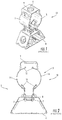
- FIGS. 1 and 2 One popular stackable cable hanger is discussed in U.S. Pat. No. 8,191,836 to Korczak, the disclosure of which is hereby incorporated herein by reference in its entirety.
- One such cable hanger, designated broadly at 10 is shown in FIGS. 1 and 2 .
- the hanger 10 includes curved arms 5 that extend from a flat base 6 .
- Locking projections 7 extend from the free ends of the arms 5 .
- the locking projections 7 are inserted into a reinforced hole 8 in a tower structure 4 to mount the hanger 10 thereon.
- the base 6 of the hanger 10 includes a reinforced hole 9 that can receive the projections of another hanger 10 to mount a second cable.
- the arms 5 include arcuate sections 14 that together generally define a circle within which a cable can reside.
- Two cantilevered tabs 12 extend radially inwardly and toward the base 6 at one end of the arcuate sections 14
- two cantilevered tabs 16 extend radially inwardly and toward the base 6 from the opposite ends of the arcuate sections 14 .
- the cantilevered tabs 12 , 16 are deployed to deflect radially outwardly when the hanger 10 receives a cable for mounting; this deflection generates a radially inward force from each tab 12 , 16 that grips the jacket of the cable.
- Hangers can be “stacked” onto each other by inserting the locking projections 7 of one hanger into the large hole 9 of the next hanger.
- cable hanger of this type is the SNAP-STAK® hanger, available from CommScope, Inc. (Joliet, Ill.).
- the SNAP-STAK® hanger is offered in multiple sizes that correspond to the outer diameters of different cables. This arrangement has been suitable for use with RF coaxial cables, which tend to be manufactured in only a few different outer diameters; however, the arrangement has been less desirable for fiber optic cables, which tend to be manufactured in a much greater variety of diameters. Moreover, fiber optic cables tend to be much heavier than coaxial cables (sometimes as much as three times heavier per unit foot), which induces greater load and stress on the hangers.
- FIGS. 3 and 4 One cable hanger discussed in this publication is shown in FIGS. 3 and 4 and designated broadly at 610 therein.
- the cable hanger 610 is somewhat similar to the cable hanger 10 , inasmuch as it has a base 606 , curved arms 605 and locking projections 607 that resemble those of the hanger 10 discussed above.
- the cable hanger 610 also has flex members 618 that define chords across the arcuate sections 614 of the arms 605 . As can be seen in FIG.
- cantilevered gripping members 612 , 616 extend from the flex members 618 and into the cable-gripping space S within the arms 605 . It can also be seen in FIG. 3 that the flex members 618 are tripartite, with two vertically offset horizontal runs 618 a , 618 c merging with the arcuate sections 614 of the arms 605 and a vertical run 618 b extending between the horizontal runs 618 a , 618 c .
- the gripping members 612 , 616 extend from opposite sides of the vertical run 618 b and are vertically offset from each other.
- the cable hanger 610 is employed in the same manner as the cable hanger 10 ; a cable is inserted into the space S between the arms 605 , which are then closed around the cable as the locking projections 607 are inserted into a mounting hole.
- the cantilevered gripping members 612 , 616 can help to grip and to center the cable within the space S.
- the presence of the flex members 618 which are fixed end beams rather than cantilevered tabs, can provide additional gripping force beyond that of the cable hanger 10 .
- embodiments of the invention are directed to a cable hanger assembly.
- the assembly comprises: a mounting substrate, the mounting substrate including a plurality of holes configured to receive clips; and a plurality of clips, each of the clips configured to receive a cable and mount in one of the plurality of holes of the mounting substrate.
- the cable hanger assembly is employed in combination with a plurality of cables mounted to the mounting substrate, wherein each of the cables is mounted with a respective one of the plurality of clips.
- embodiments of the invention are directed to a cable hanger assembly comprising: a mounting substrate, the mounting substrate having a main panel, wherein a plurality of holes configured to receive clips are located in the main panel; and a plurality of clips, each of the clips configured to receive a cable and mount in one of the plurality of holes of the mounting substrate.
- embodiments of the invention are directed to a cable hanger assembly comprising: a mounting substrate, the mounting substrate including a base, a pair of arms attached to the base, and locking features attached to free ends of the arms, wherein each of the arms includes a plurality of holes configured to receive clips; and a plurality of clips, each of the clips configured to receive a cable and mount in one of the plurality of holes of the mounting substrate.
- FIG. 1 is a perspective view of a prior art cable hanger.
- FIG. 2 is a top view of the prior art cable hanger of FIG. 1 .
- FIG. 3 is a perspective view of another prior art cable hanger.
- FIG. 4 is a top view of the cable hanger of FIG. 3 .
- FIG. 5 is a front view of a mounting substrate of a cable hanger assembly according to embodiments of the invention.
- FIG. 6A is a top view of a clip to be used with the cable hanger assembly of FIG. 5 .
- FIG. 6B is a top view of an alternative clip to be used with the cable hanger assembly of FIG. 5 .
- FIG. 7 is a top view of the mounting substrate of FIG. 5 mounted on a mounting structure with clips of FIG. 6A inserted therein to hold cables.
- FIG. 8 is a top view of a mounting substrate of a cable hanger assembly according to alternative embodiments of the invention, with clips of FIG. 6A inserted therein to hold cables.
- FIG. 9 is a side view of the mounting substrate of FIG. 8 .
- FIG. 10 is a top view of two cable hanger assemblies of FIG. 8 mounted in a stacked fashion.
- the assembly 110 includes a mounting substrate 120 and a plurality of clips 130 . These are described in greater detail below.
- the mounting substrate 120 includes a generally square, generally flat main panel 122 with four side edges 123 .
- sixteen mounting holes 124 define a 4 ⁇ 4 grid, although other numbers, sizes and arrangements of holes 124 may also be suitable.
- Locking features 126 (which may take the form of the locking projections 107 , 607 discussed above) are located in the central portion of the main panel 122 .
- the locking features 126 are configured to be inserted into a mounting hole (typically nominally 3 ⁇ 4 inch in diameter) of a mounting structure such as an antenna tower or the like.
- the mounting substrate 120 discussed above is typically formed of a metallic material, such as steel, and may be formed as a monolithic member (often from a flat blank stamped from sheet steel and bent into a desired shape).
- the clip 130 is generally U-shaped, with two arms 131 that merge into a central base 132 (as shown in FIG. 6A , the base 132 may be somewhat wider than the distance between the arms 131 ).
- a locking feature such as a hook 134 , is located on the end of each arm 131 .
- Gripping barbs 135 are located on the base 132 and extend radially inwardly. (Alternatively, gripping features other than barbs may be employed, such as the lances 135 ′ on clip 130 ′ shown in FIG.
- the clips 130 , 130 ′ discussed above should be formed of a flexible, resilient material, such as a metallic material (e.g., steel) or a polymeric material, and may be formed as a monolithic member (often from a flat blank stamped from sheet steel and bent into a desired shape or via injection molding).
- a metallic material e.g., steel
- a polymeric material e.g., polyethylene
- the mounting substrate 120 is mounted to a mounting structure 170 , such as an antenna tower, by inserting the locking features 126 into a mounting hole 172 in the mounting structure 170 .
- the locking features 126 are deflected toward each other from a relaxed state, then inserted into the hole 172 (typically 3 ⁇ 4 inch) in the mounting structure 170 in the deflected condition.
- the locking features 126 exert outward pressure on edges of the hole and maintain the cable hanger 110 in a mounted position on the mounting structure 170 .
- a cable 150 can then be mounted onto the mounting substrate 120 by capturing the cable 150 in the base portion 132 of the clip 130 and inserting the hooks 134 of the clip 130 into one of the holes 124 in the mounting substrate 120 .
- the clips 130 extend away from the main panel 122 in a direction generally opposite that of the locking features 126 .
- the presence of the hooks 134 secures the clip 130 in place, and the barbs 135 of the clip 130 assist in gripping the cable 150 .
- the process can be repeated with additional cables 150 and additional clips 130 ( FIG. 7 shows four cables 150 mounted on the mounting substrate 120 ).
- the number, size and locations of the holes 124 may vary: the holes may be single or dual slots; more or fewer holes 124 may be included; the holes 124 may be larger or smaller, or may vary in size within the same mounting substrate 120 ; and the holes 124 may be located in different locations on the main panel 122 (for example, offset from each other) or even in the side edges 123 .
- the side edges 123 may be formed differently, or some or all of the side edges 123 may be omitted entirely.
- the mounting substrate 120 not not be square, but could be rectangular, circular, oval, or a number of other shapes. Other variations are also contemplated.
- the assembly 210 includes a mounting substrate 220 that is somewhat similar to the cable hangers 10 , 610 discussed above, with a base 206 , arms 205 that extend from ends of the base 206 , and locking projections 207 on the arms 205 .
- the arms 205 are tripartite, with serially merging segments 205 a , 205 b , 205 c ; as can be seen in FIG. 8 , the segments 205 a and 205 c and generally parallel with each other and perpendicular to the segment 205 b , and the locking projections 207 extend from segments 205 c .
- a mounting hole 209 is present in the base 206 .
- each segment 205 a of the arms 205 includes three holes 212 .
- the holes 212 are configured to receive clips 230 similar to clips 130 , 130 ′ discussed above.
- Each of the clips 230 can capture and secure a cable 250 to the mounting substrate 220 .
- the cables 250 can either be secured within the perimeter of the mounting substrate 220 or outside of the perimeter (both are shown in FIG. 8 ).
- the mounting substrates 220 are “stackable.” More specifically, the locking projections 207 ′ of a second mounting substrate 220 ′ can be inserted into the mounting hole 209 of a first mounting substrate 220 that is mounted to a mounting structure 270 . Additional mounting substrates 220 can be further stacked. Each of the mounting substrates 220 can be used for the mounting of multiple cables with clips 230 .
- any or all of the segments 205 a , 205 b , 205 c of the arms 205 and/or the base 206 may include curved or bent portions as desired. All of the clips 230 may be inserted internally (i.e., within the periphery of the mounting substrate 220 ) or externally (i.e., outside of the periphery of the mounting substrate 220 ), or some clips 230 may be inserted internally and others externally.
- the mounting substrate 220 may lack the mounting hole 220 , in which case the mounting substrate 220 may not be stackable; in such an instance, additional holes may be present in the base 206 for the mounting of more clips 230 . Other variations may also be possible.
- clips 130 , 130 ′, 230 may be used on the same mounting substrate 120 , 220 , and/or different sizes of cables may be mounted to a single mounting substrate 120 , 220 .
Landscapes
- Engineering & Computer Science (AREA)
- General Engineering & Computer Science (AREA)
- Mechanical Engineering (AREA)
- Architecture (AREA)
- Civil Engineering (AREA)
- Structural Engineering (AREA)
- Clamps And Clips (AREA)
- Installation Of Indoor Wiring (AREA)
Abstract
A cable hanger assembly includes: a mounting substrate, the mounting substrate including a plurality of holes configured to receive clips; and a plurality of clips, each of the clips configured to receive a cable and mount in one of the plurality of holes of the mounting substrate.
Description
The present application is a continuation of and claims priority to U.S. patent application Ser. No. 15/856,201, filed Dec. 28, 2017, now U.S. Pat. No. 10,634,265, which claims priority from and the benefit of U.S. Provisional Patent Application No. 62/447,929, filed Jan. 19, 2017, the disclosure of which is hereby incorporated herein in its entirety.
The present invention relates generally to devices for supporting cables and, in particular, to hangers for securing cables to support structures.
Cable hangers are commonly used to secure cables to structural members of antenna towers and or along tunnel walls. Generally, each cable is attached to a structural member by cable hangers mounted at periodically-spaced attachment points.
Antenna towers and/or tunnels may be crowded due to the large numbers of cables required for signal-carrying. Over time, as systems are added, upgraded and/or expanded, installation of additional cables may be required. To conserve space, it may be desirable for each set of cable hangers to secure more than a single cable. Certain cable hangers have been constructed to secure multiple cables; other cable hangers have a stackable construction that permits multiple cable hangers to be interlocked extending outwardly from each mounting point/structural member. Stacked and multiple-cable-type cable hangers significantly increase the number of cables mountable to a single attachment point.
One popular stackable cable hanger is discussed in U.S. Pat. No. 8,191,836 to Korczak, the disclosure of which is hereby incorporated herein by reference in its entirety. One such cable hanger, designated broadly at 10, is shown in FIGS. 1 and 2 . The hanger 10 includes curved arms 5 that extend from a flat base 6. Locking projections 7 extend from the free ends of the arms 5. As can be seen in FIGS. 1 and 2 , the locking projections 7 are inserted into a reinforced hole 8 in a tower structure 4 to mount the hanger 10 thereon. The base 6 of the hanger 10 includes a reinforced hole 9 that can receive the projections of another hanger 10 to mount a second cable.
As can be best seen in FIG. 2 , the arms 5 include arcuate sections 14 that together generally define a circle within which a cable can reside. Two cantilevered tabs 12 extend radially inwardly and toward the base 6 at one end of the arcuate sections 14, and two cantilevered tabs 16 extend radially inwardly and toward the base 6 from the opposite ends of the arcuate sections 14. The cantilevered tabs 12, 16 are deployed to deflect radially outwardly when the hanger 10 receives a cable for mounting; this deflection generates a radially inward force from each tab 12, 16 that grips the jacket of the cable.
Hangers can be “stacked” onto each other by inserting the locking projections 7 of one hanger into the large hole 9 of the next hanger. One variety of cable hanger of this type is the SNAP-STAK® hanger, available from CommScope, Inc. (Joliet, Ill.).
The SNAP-STAK® hanger is offered in multiple sizes that correspond to the outer diameters of different cables. This arrangement has been suitable for use with RF coaxial cables, which tend to be manufactured in only a few different outer diameters; however, the arrangement has been less desirable for fiber optic cables, which tend to be manufactured in a much greater variety of diameters. Moreover, fiber optic cables tend to be much heavier than coaxial cables (sometimes as much as three times heavier per unit foot), which induces greater load and stress on the hangers.
Multiple approaches to addressing this issue are offered in co-assigned and co-pending U.S. Patent Publication No. 2016/0281881 to Vaccaro, the disclosure of which is hereby incorporated herein by reference in full. One cable hanger discussed in this publication is shown in FIGS. 3 and 4 and designated broadly at 610 therein. The cable hanger 610 is somewhat similar to the cable hanger 10, inasmuch as it has a base 606, curved arms 605 and locking projections 607 that resemble those of the hanger 10 discussed above. However, the cable hanger 610 also has flex members 618 that define chords across the arcuate sections 614 of the arms 605. As can be seen in FIG. 4 , cantilevered gripping members 612, 616 extend from the flex members 618 and into the cable-gripping space S within the arms 605. It can also be seen in FIG. 3 that the flex members 618 are tripartite, with two vertically offset horizontal runs 618 a, 618 c merging with the arcuate sections 614 of the arms 605 and a vertical run 618 b extending between the horizontal runs 618 a, 618 c. The gripping members 612, 616 extend from opposite sides of the vertical run 618 b and are vertically offset from each other.
In use, the cable hanger 610 is employed in the same manner as the cable hanger 10; a cable is inserted into the space S between the arms 605, which are then closed around the cable as the locking projections 607 are inserted into a mounting hole. The cantilevered gripping members 612, 616 can help to grip and to center the cable within the space S. The presence of the flex members 618, which are fixed end beams rather than cantilevered tabs, can provide additional gripping force beyond that of the cable hanger 10.
In view of the foregoing, it may be desirable to provide additional configurations of cable hangers to enable a technician to adapt to different cable sizes and mounting conditions.
As a first aspect, embodiments of the invention are directed to a cable hanger assembly. The assembly comprises: a mounting substrate, the mounting substrate including a plurality of holes configured to receive clips; and a plurality of clips, each of the clips configured to receive a cable and mount in one of the plurality of holes of the mounting substrate.
In some embodiments, the cable hanger assembly is employed in combination with a plurality of cables mounted to the mounting substrate, wherein each of the cables is mounted with a respective one of the plurality of clips.
As a second aspect, embodiments of the invention are directed to a cable hanger assembly comprising: a mounting substrate, the mounting substrate having a main panel, wherein a plurality of holes configured to receive clips are located in the main panel; and a plurality of clips, each of the clips configured to receive a cable and mount in one of the plurality of holes of the mounting substrate.
As a third aspect, embodiments of the invention are directed to a cable hanger assembly comprising: a mounting substrate, the mounting substrate including a base, a pair of arms attached to the base, and locking features attached to free ends of the arms, wherein each of the arms includes a plurality of holes configured to receive clips; and a plurality of clips, each of the clips configured to receive a cable and mount in one of the plurality of holes of the mounting substrate.
The present invention is described with reference to the accompanying drawings, in which certain embodiments of the invention are shown. This invention may, however, be embodied in many different forms and should not be construed as limited to the embodiments that are pictured and described herein; rather, these embodiments are provided so that this disclosure will be thorough and complete, and will fully convey the scope of the invention to those skilled in the art. It will also be appreciated that the embodiments disclosed herein can be combined in any way and/or combination to provide many additional embodiments.
Unless otherwise defined, all technical and scientific terms that are used in this disclosure have the same meaning as commonly understood by one of ordinary skill in the art to which this invention belongs. The terminology used in the below description is for the purpose of describing particular embodiments only and is not intended to be limiting of the invention. As used in this disclosure, the singular foul's “a”, “an” and “the” are intended to include the plural forms as well, unless the context clearly indicates otherwise. It will also be understood that when an element (e.g., a device, circuit, etc.) is referred to as being “attached”, “connected” or “coupled” to another element, it can be directly connected or coupled to the other element or intervening elements may be present. In contrast, when an element is referred to as being “directly attached”, “directly connected” or “directly coupled” to another element, there are no intervening elements present.
Referring now to the drawings, a cable hanger assembly 110 according to embodiments of the invention is shown in FIGS. 5-7 . The assembly 110 includes a mounting substrate 120 and a plurality of clips 130. These are described in greater detail below.
The mounting substrate 120 includes a generally square, generally flat main panel 122 with four side edges 123. In the main panel 122, sixteen mounting holes 124 define a 4×4 grid, although other numbers, sizes and arrangements of holes 124 may also be suitable. Locking features 126 (which may take the form of the locking projections 107, 607 discussed above) are located in the central portion of the main panel 122. The locking features 126 are configured to be inserted into a mounting hole (typically nominally ¾ inch in diameter) of a mounting structure such as an antenna tower or the like.
Those skilled in this art will appreciate that the mounting substrate 120 discussed above is typically formed of a metallic material, such as steel, and may be formed as a monolithic member (often from a flat blank stamped from sheet steel and bent into a desired shape).
Referring now to FIG. 6A , a clip 130 is shown therein. The clip 130 is generally U-shaped, with two arms 131 that merge into a central base 132 (as shown in FIG. 6A , the base 132 may be somewhat wider than the distance between the arms 131). A locking feature, such as a hook 134, is located on the end of each arm 131. Gripping barbs 135 are located on the base 132 and extend radially inwardly. (Alternatively, gripping features other than barbs may be employed, such as the lances 135′ on clip 130′ shown in FIG. 6B , or ridges, edges, nubs, dimples and the like, that enhance gripping of a cable, facilitate insertion of a cable, or both. Examples of such features are described in co-assigned and co-pending U.S. patent application Ser. No. 15/335,614, filed Oct. 27, 2016, the disclosure of which is hereby incorporated herein in its entirety.)
Those skilled in this art will appreciate that the clips 130, 130′ discussed above should be formed of a flexible, resilient material, such as a metallic material (e.g., steel) or a polymeric material, and may be formed as a monolithic member (often from a flat blank stamped from sheet steel and bent into a desired shape or via injection molding).
As can be seen in FIG. 7 , in use the mounting substrate 120 is mounted to a mounting structure 170, such as an antenna tower, by inserting the locking features 126 into a mounting hole 172 in the mounting structure 170. The locking features 126 are deflected toward each other from a relaxed state, then inserted into the hole 172 (typically ¾ inch) in the mounting structure 170 in the deflected condition. The locking features 126 exert outward pressure on edges of the hole and maintain the cable hanger 110 in a mounted position on the mounting structure 170.
A cable 150 can then be mounted onto the mounting substrate 120 by capturing the cable 150 in the base portion 132 of the clip 130 and inserting the hooks 134 of the clip 130 into one of the holes 124 in the mounting substrate 120. The clips 130 extend away from the main panel 122 in a direction generally opposite that of the locking features 126. The presence of the hooks 134 secures the clip 130 in place, and the barbs 135 of the clip 130 assist in gripping the cable 150. The process can be repeated with additional cables 150 and additional clips 130 (FIG. 7 shows four cables 150 mounted on the mounting substrate 120).
Those skilled in this art will appreciate that other variations of the mounting substrate 120 may also be suitable. For example, the number, size and locations of the holes 124 may vary: the holes may be single or dual slots; more or fewer holes 124 may be included; the holes 124 may be larger or smaller, or may vary in size within the same mounting substrate 120; and the holes 124 may be located in different locations on the main panel 122 (for example, offset from each other) or even in the side edges 123. The side edges 123 may be formed differently, or some or all of the side edges 123 may be omitted entirely. The mounting substrate 120 not not be square, but could be rectangular, circular, oval, or a number of other shapes. Other variations are also contemplated.
Referring now to FIGS. 8-10 , another cable hanger assembly, designated broadly at 210, is shown therein. The assembly 210 includes a mounting substrate 220 that is somewhat similar to the cable hangers 10, 610 discussed above, with a base 206, arms 205 that extend from ends of the base 206, and locking projections 207 on the arms 205. The arms 205 are tripartite, with serially merging segments 205 a, 205 b, 205 c; as can be seen in FIG. 8 , the segments 205 a and 205 c and generally parallel with each other and perpendicular to the segment 205 b, and the locking projections 207 extend from segments 205 c. A mounting hole 209 is present in the base 206.
It can be seen in FIG. 9 that each segment 205 a of the arms 205 includes three holes 212. As shown in FIG. 8 , the holes 212 are configured to receive clips 230 similar to clips 130, 130′ discussed above. Each of the clips 230 can capture and secure a cable 250 to the mounting substrate 220. The cables 250 can either be secured within the perimeter of the mounting substrate 220 or outside of the perimeter (both are shown in FIG. 8 ).
Referring now to FIG. 10 , it can be seen that the mounting substrates 220 are “stackable.” More specifically, the locking projections 207′ of a second mounting substrate 220′ can be inserted into the mounting hole 209 of a first mounting substrate 220 that is mounted to a mounting structure 270. Additional mounting substrates 220 can be further stacked. Each of the mounting substrates 220 can be used for the mounting of multiple cables with clips 230.
Those skilled in this art will appreciate that other variations of the mounting substrate 220 may be suitable. For example, any or all of the segments 205 a, 205 b, 205 c of the arms 205 and/or the base 206 may include curved or bent portions as desired. All of the clips 230 may be inserted internally (i.e., within the periphery of the mounting substrate 220) or externally (i.e., outside of the periphery of the mounting substrate 220), or some clips 230 may be inserted internally and others externally. The mounting substrate 220 may lack the mounting hole 220, in which case the mounting substrate 220 may not be stackable; in such an instance, additional holes may be present in the base 206 for the mounting of more clips 230. Other variations may also be possible.
It should also be appreciated that different sizes of clips 130, 130′, 230 may be used on the same mounting substrate 120, 220, and/or different sizes of cables may be mounted to a single mounting substrate 120, 220.
The foregoing is illustrative of the present invention and is not to be construed as limiting thereof. Although exemplary embodiments of this invention have been described, those skilled in the art will readily appreciate that many modifications are possible in the exemplary embodiments without materially departing from the novel teachings and advantages of this invention. Accordingly, all such modifications are intended to be included within the scope of this invention as defined in the claims. The invention is defined by the following claims, with equivalents of the claims to be included therein.
Claims (17)
1. A cable hanger assembly, comprising:
a mounting substrate comprising a main panel, wherein a plurality of holes configured to receive clips are located in the main panel; and
a plurality of clips, each of the clips configured to receive a cable, each of the clips mounted in one of the plurality of holes of the mounting substrate;
wherein the mounting substrate further comprises locking features that enable the mounting substrate to be mounted in a hole in a mounting structure, the mounting substrate formed as a monolithic member.
2. The cable hanger assembly defined in claim 1 , wherein the plurality of holes are arranged in a grid on the main panel.
3. The cable hanger assembly defined in claim 1 , wherein the locking features extend generally perpendicularly away from the main panel in a first direction, and wherein the clips are configured to mount on the main panel and extend away from the main panel in a second direction that is generally opposite to the first direction.
4. The cable hanger assembly defined in claim 1 , wherein each of the plurality of clips includes a gripping feature configured to enhance grip on a cable.
5. The cable hanger assembly defined in claim 1 , in combination with a plurality of cables mounted to the mounting substrate, each of the cables mounted with a respective one of the plurality of clips.
6. The cable hanger assembly defined in claim 5 , wherein at least some of the plurality of cables have a different diameter than at least some others of the plurality of cables.
7. The cable hanger assembly defined in claim 1 , wherein the main panel is generally planar.
8. A cable hanger assembly, comprising:
a mounting substrate comprising a generally planar main panel, wherein a plurality of holes configured to receive clips are located in the main panel; and
a plurality of clips, each of the clips configured to receive a cable, each of the clips mounted in one of the plurality of holes of the mounting substrate;
wherein the mounting substrate further comprises locking features that enable the mounting substrate to be mounted in a hole in a mounting structure, the locking features extending generally perpendicularly away from the main panel in a first direction from a location within the plurality of holes, the mounting substrate formed as a monolithic member.
9. The cable hanger assembly defined in claim 8 , wherein the plurality of holes are arranged in a grid on the main panel.
10. The cable hanger assembly defined in claim 8 , wherein the clips are configured to mount on the main panel and extend away from the main panel in a second direction that is generally opposite to the first direction.
11. The cable hanger assembly defined in claim 8 , wherein each of the plurality of clips includes a gripping feature configured to enhance grip on a cable.
12. The cable hanger assembly defined in claim 8 , in combination with a plurality of cables mounted to the mounting substrate, each of the cables mounted with a respective one of the plurality of clips.
13. The cable hanger assembly defined in claim 12 , wherein at least some of the plurality of cables have a different diameter than at least some others of the plurality of cables.
14. A cable hanger assembly, comprising:
a mounting substrate comprising a generally planar main panel, wherein a plurality of holes configured to receive clips are located in the main panel and are arranged in a two-dimensional grid; and
a plurality of clips, each of the clips configured to receive a cable, each of the clips mounted in one of the plurality of holes of the mounting substrate;
wherein the mounting substrate further comprises locking features that enable the mounting substrate to be mounted in a hole in a mounting structure, the locking features extending generally perpendicularly away from the main panel in a first direction from a location within the plurality of holes, the mounting substrate formed as a monolithic member; and
wherein the clips are configured to mount on the main panel and extend away from the main panel in a second direction that is generally opposite to the first direction.
15. The cable hanger assembly defined in claim 14 , wherein each of the plurality of clips includes a gripping feature configured to enhance grip on a cable.
16. The cable hanger assembly defined in claim 14 , in combination with a plurality of cables mounted to the mounting substrate, each of the cables mounted with a respective one of the plurality of clips.
17. The cable hanger assembly defined in claim 16 , wherein at least some of the plurality of cables have a different diameter than at least some others of the plurality of cables.
Priority Applications (1)
| Application Number | Priority Date | Filing Date | Title |
|---|---|---|---|
| US16/854,159 US10859187B2 (en) | 2017-01-19 | 2020-04-21 | Hanger assembly for mounting multiple cables |
Applications Claiming Priority (3)
| Application Number | Priority Date | Filing Date | Title |
|---|---|---|---|
| US201762447929P | 2017-01-19 | 2017-01-19 | |
| US15/856,201 US10634265B2 (en) | 2017-01-19 | 2017-12-28 | Hanger assembly for mounting multiple cables |
| US16/854,159 US10859187B2 (en) | 2017-01-19 | 2020-04-21 | Hanger assembly for mounting multiple cables |
Related Parent Applications (1)
| Application Number | Title | Priority Date | Filing Date |
|---|---|---|---|
| US15/856,201 Continuation US10634265B2 (en) | 2017-01-19 | 2017-12-28 | Hanger assembly for mounting multiple cables |
Publications (2)
| Publication Number | Publication Date |
|---|---|
| US20200256483A1 US20200256483A1 (en) | 2020-08-13 |
| US10859187B2 true US10859187B2 (en) | 2020-12-08 |
Family
ID=62838328
Family Applications (2)
| Application Number | Title | Priority Date | Filing Date |
|---|---|---|---|
| US15/856,201 Active US10634265B2 (en) | 2017-01-19 | 2017-12-28 | Hanger assembly for mounting multiple cables |
| US16/854,159 Active US10859187B2 (en) | 2017-01-19 | 2020-04-21 | Hanger assembly for mounting multiple cables |
Family Applications Before (1)
| Application Number | Title | Priority Date | Filing Date |
|---|---|---|---|
| US15/856,201 Active US10634265B2 (en) | 2017-01-19 | 2017-12-28 | Hanger assembly for mounting multiple cables |
Country Status (4)
| Country | Link |
|---|---|
| US (2) | US10634265B2 (en) |
| EP (1) | EP3571746A4 (en) |
| CN (2) | CN114421391A (en) |
| WO (1) | WO2018136210A1 (en) |
Cited By (1)
| Publication number | Priority date | Publication date | Assignee | Title |
|---|---|---|---|---|
| RU208272U1 (en) * | 2021-09-10 | 2021-12-13 | Максим Никитич Бажов | Cable fixing device |
Families Citing this family (9)
| Publication number | Priority date | Publication date | Assignee | Title |
|---|---|---|---|---|
| US10663088B2 (en) * | 2016-11-11 | 2020-05-26 | Commscope Technologies Llc | Adapter for mounting cables and cable hangers |
| EP3549213A4 (en) | 2016-11-30 | 2020-07-01 | Commscope Technologies LLC | Hanger for mounting multiple cables |
| US10760714B2 (en) | 2016-12-14 | 2020-09-01 | Commscope Technologies Llc | Insert for mounting multiple cables in cable hanger |
| WO2018118528A1 (en) | 2016-12-21 | 2018-06-28 | Commscope Technologies Llc | Hanger for mounting multiple cables |
| CN114421391A (en) | 2017-01-19 | 2022-04-29 | 康普技术有限责任公司 | Hanger assembly for mounting a plurality of cables |
| US10935105B2 (en) * | 2019-04-23 | 2021-03-02 | ConcealFab Corporation | Low-PIM angle adapters and cable hanger assemblies |
| US11326666B2 (en) * | 2019-04-23 | 2022-05-10 | ConcealFab Corporation | Low-PIM rod receiver angle adapters and cable hanger assemblies |
| US11437800B2 (en) * | 2020-03-26 | 2022-09-06 | Commscope Technologies Llc | Adapter assemblies and arrangements for mounting cables |
| US11913575B2 (en) | 2021-03-31 | 2024-02-27 | Commscope Technologies Llc | Cable hanger with tying section and stabilizing members |
Citations (140)
| Publication number | Priority date | Publication date | Assignee | Title |
|---|---|---|---|---|
| US1376284A (en) | 1920-06-01 | 1921-04-26 | John A Kohn | Clamp |
| US1452497A (en) | 1921-06-29 | 1923-04-24 | American Car & Foundry Co | Pipe clamp for steam coils |
| US2032413A (en) | 1933-02-21 | 1936-03-03 | Superheater Co Ltd | Superheater support |
| US2166916A (en) | 1937-05-25 | 1939-07-18 | Albert H Tinnerman | Clip for mounting cables and like objects |
| US2179406A (en) | 1938-03-25 | 1939-11-07 | Fitzpatrick Ray | Rack |
| US2375513A (en) | 1943-09-30 | 1945-05-08 | William F Bach | Pipe hanger system |
| US2447025A (en) | 1945-05-25 | 1948-08-17 | Bruce K Newman | Cable separator and yoke |
| US2453980A (en) | 1946-10-28 | 1948-11-16 | Tinnerman Products Inc | Fastening device for cables, wires, or the like |
| US2470814A (en) | 1948-03-04 | 1949-05-24 | Hain Max | Electrical cable support or rack |
| US2495848A (en) | 1948-04-06 | 1950-01-31 | Bertha K Kiesel | Spring clip |
| US2560845A (en) | 1948-01-26 | 1951-07-17 | John A Carpenter | Hanger |
| DE845808C (en) | 1945-10-19 | 1952-08-04 | Dunlop Rubber Co | Device for fastening cables, pipes, rods or the like to plate material |
| US2605865A (en) | 1948-04-29 | 1952-08-05 | Lab Furniture Company Inc | Island strip support |
| US2723431A (en) | 1952-01-14 | 1955-11-15 | Renzo Simon Di | Clamping and holding device for flexible hose |
| US2746110A (en) | 1954-09-29 | 1956-05-22 | United Carr Fastener Corp | Panel engaging fastening device |
| US2990150A (en) | 1959-03-06 | 1961-06-27 | Robert M Weigel | Goffered wire clip bank |
| US3042352A (en) | 1960-04-22 | 1962-07-03 | George F Stamper | Pipe hanger |
| US3050578A (en) | 1958-08-07 | 1962-08-21 | Gen Motors Corp | Retainer |
| US3163712A (en) | 1960-01-26 | 1964-12-29 | United Carr Inc | Wiring clip having a stud engagement means |
| US3179969A (en) | 1963-10-04 | 1965-04-27 | Tridon Mfg Ltd | Automobile windshield wiper backing members |
| US3404858A (en) | 1966-10-07 | 1968-10-08 | Levy Erwin | Conduit support bracket |
| US3430904A (en) | 1966-12-19 | 1969-03-04 | Illinois Tool Works | Fastening device |
| US3485467A (en) | 1967-04-26 | 1969-12-23 | Bell Telephone Labor Inc | Telephone wire pair clip |
| US3501117A (en) | 1968-05-31 | 1970-03-17 | Illinois Tool Works | Clip device |
| US3536281A (en) | 1968-01-04 | 1970-10-27 | Illinois Tool Works | Bracket structure |
| US3599915A (en) | 1969-12-10 | 1971-08-17 | Illinois Tool Works | Pipe clip |
| FR2145985A6 (en) | 1971-07-09 | 1973-02-23 | United Carr Ltd | |
| FR2176184A5 (en) | 1972-03-13 | 1973-10-26 | Rapid Sa | |
| DE2401187A1 (en) | 1973-06-12 | 1975-01-09 | Zentronik Veb K | CABLE CLAMP |
| US3916089A (en) | 1974-06-10 | 1975-10-28 | Envirotech Corp | Bracket for conductors |
| US3981048A (en) | 1975-12-29 | 1976-09-21 | Panduit Corporation | Smooth exterior dual clamp |
| US4148113A (en) | 1977-05-23 | 1979-04-10 | The Echlin Manufacturing Company | Clamp for securing a plurality of elongated articles |
| DE2903306A1 (en) | 1978-01-31 | 1979-08-02 | Telemecanique Electrique | DEVICE FOR FASTENING GUTTERS FOR GUIDING LADDERS |
| US4244542A (en) | 1978-06-04 | 1981-01-13 | Mathews Lyle H | Conduit spacer system |
| GB1599416A (en) | 1978-02-23 | 1981-09-30 | Oldbury Ltd Isaiah | Retaining clip |
| US4295618A (en) | 1978-11-15 | 1981-10-20 | Nissan Motor Co., Ltd. | Device for fixing pipes, rods and other elongated bodies |
| US4306697A (en) | 1980-06-16 | 1981-12-22 | Mathews Lyle H | Conduit spacer system |
| JPS5775283A (en) | 1980-10-28 | 1982-05-11 | Hashimoto Forming Co Ltd | Method and device for welding of metallic plate material |
| US4344480A (en) | 1978-03-30 | 1982-08-17 | Ecolaire Incorporated | Support for heat exchange tubes |
| US4356987A (en) | 1980-04-28 | 1982-11-02 | Patentverwertungs-Und Finanzierungsgesellschaft Serania Ag | Support clip for electrical conductors or tubes |
| JPS61200974A (en) | 1985-02-27 | 1986-09-05 | サンド アクチエンゲゼルシヤフト | Manufacture of stilbene derivative |
| US4669156A (en) | 1984-11-12 | 1987-06-02 | Guido Juergen Dipl Ing | Pipe clip of resilient material |
| US4795856A (en) | 1987-03-04 | 1989-01-03 | Aluma-Form, Inc. | Apparatus for supporting fiber optic or related cable |
| DE3823578A1 (en) | 1987-07-28 | 1989-02-09 | Lothar Ing Grad Eckert | Pipe-securing band and process and apparatus for producing the same |
| US4813639A (en) | 1987-10-01 | 1989-03-21 | Andrew Corporation | Cluster mounting system for supporting coaxial cables and the like |
| USD305099S (en) | 1987-11-09 | 1989-12-19 | Yazaki Corporation | Clamping strap for electrical wires |
| US5035383A (en) | 1989-02-16 | 1991-07-30 | Rockwell International Corporation | Space saver service clamp |
| US5085384A (en) | 1989-11-24 | 1992-02-04 | Hydac Technology Gmbh | Power line attachment system |
| US5149027A (en) | 1992-01-31 | 1992-09-22 | Alcatel Network Systems, Inc. | Multiple leg height snap fit cable holder apparatus |
| US5188318A (en) | 1991-06-27 | 1993-02-23 | Newcomer Charles H | Stud engaging electrical wiring clip |
| US5320312A (en) | 1993-05-05 | 1994-06-14 | Stainless, Inc. | Cable cluster mount |
| US5393021A (en) | 1994-03-07 | 1995-02-28 | Cablewave Systems | Cable hanger |
| USD357802S (en) | 1993-08-19 | 1995-05-02 | Pro Release, Inc. | Combined bow and arrow holder |
| JPH0886386A (en) | 1994-09-16 | 1996-04-02 | Nissan Diesel Motor Co Ltd | Pipe supporting device for vehicle |
| US5587555A (en) | 1994-06-03 | 1996-12-24 | B-Line Systems, Inc. | Conductor holding device |
| JPH09144719A (en) | 1995-11-27 | 1997-06-03 | Ochiai:Kk | Cable fastener |
| US5677513A (en) | 1993-10-21 | 1997-10-14 | Sumitomo Wiring Systems, Ltd. | Tying device for wiring harness |
| JPH1019168A (en) | 1996-06-28 | 1998-01-23 | Piolax Inc | Holding clip |
| US5833188A (en) | 1994-12-20 | 1998-11-10 | Twofish Unlimited | Accessory mounting apparatus |
| US5876000A (en) | 1997-11-06 | 1999-03-02 | Sioux Chief Manufacturing Company, Inc. | Universal pipe bracket |
| US5921520A (en) | 1995-08-03 | 1999-07-13 | Wisniewski; David M. | Bracket for mounting a fuel filter |
| JPH11223281A (en) | 1998-02-05 | 1999-08-17 | Inaba Denki Sangyo Co Ltd | Rack for supporting pipe |
| US5971329A (en) | 1996-11-20 | 1999-10-26 | 3244 Corporation | Conduit support |
| US6317933B1 (en) | 1999-01-14 | 2001-11-20 | Ykk Corporation | Binding band |
| US6323430B1 (en) | 1999-07-28 | 2001-11-27 | Itt Manufacturing Enterprises, Inc. | S-shaped cable holding clamp with grounding |
| US20020005463A1 (en) | 1999-01-12 | 2002-01-17 | Paske Jamie M. | Stackable transmission line hanger |
| US20020012582A1 (en) | 1998-12-17 | 2002-01-31 | Karsten Kirkegaard | Wind mill with a suspension for cables and the like, such suspension for cables and the like and a holder for such suspension |
| US6354543B1 (en) | 1999-01-12 | 2002-03-12 | Andrew Corporation | Stackable transmission line hanger |
| JP2002130539A (en) | 2000-10-18 | 2002-05-09 | Cr Unit:Kk | Pipe supporting trestle |
| US6580867B2 (en) | 2000-07-13 | 2003-06-17 | Alcatel | Support for small-diameter filamentary elements and a bundle of filamentary elements held together by the support |
| US20030173470A1 (en) | 2002-03-12 | 2003-09-18 | Geiger Gerard G. | Conduit Isolator Mount |
| US20040113027A1 (en) | 2001-02-14 | 2004-06-17 | Hideaki Nakanishi | Fastener for pipe or the like |
| US20040251386A1 (en) | 2003-04-07 | 2004-12-16 | Newfrey Llc | Antivibration clamp for elongated objects |
| US20050109887A1 (en) | 2003-11-26 | 2005-05-26 | Catapano Joseph P. | Cable holder |
| US20050253025A1 (en) | 2004-05-13 | 2005-11-17 | Benoit Thomas A | Holding clip |
| US20060108480A1 (en) | 2002-11-04 | 2006-05-25 | Andrew Corporation | Line hanger |
| US20060237217A1 (en) | 2005-04-25 | 2006-10-26 | Cable Components Group, Llc. | Variable diameter conduit tubes for high performance, multi-media communication cable |
| US7131792B2 (en) | 2004-04-06 | 2006-11-07 | Mark Doverspike | Alignment and support apparatus |
| US20060249633A1 (en) | 2001-11-09 | 2006-11-09 | Rick Korczak | Anchor rail adapter and hanger and method |
| US20070007397A1 (en) | 2005-07-07 | 2007-01-11 | Panduit Corp. | Cable bracket and strap assembly |
| US20070120023A1 (en) | 2005-11-29 | 2007-05-31 | Cnh America Llc | Hydraulic hose retention device |
| US20070246616A1 (en) | 2006-04-21 | 2007-10-25 | Michael Budagher | Stackable transmission line hanger |
| US20080093510A1 (en) | 2006-10-23 | 2008-04-24 | Oh Michael H-S | Cable support and method |
| US20080115448A1 (en) | 2006-11-21 | 2008-05-22 | Kodi Jon R | Bar Connecting Apparatus |
| US7384018B2 (en) | 2005-08-05 | 2008-06-10 | Moretto S.P.A. | Device for fixing pipes to supporting structures |
| WO2008082595A1 (en) | 2006-12-29 | 2008-07-10 | Andrew Corporation | Stackable cable hanger |
| US7500644B2 (en) | 2003-06-27 | 2009-03-10 | Snecma | Device for maintaining and positioning harnesses on a turbo-jet engine |
| US7518058B1 (en) | 2007-10-12 | 2009-04-14 | The Boeing Company | Powerfeeder spacer |
| USD597403S1 (en) | 2009-01-15 | 2009-08-04 | Cyber Power System Inc. | Cable clip |
| US20090230256A1 (en) | 2008-03-12 | 2009-09-17 | Widlacki Felix G | Adapter for stacking cable hangers |
| US20090242715A1 (en) | 2008-03-31 | 2009-10-01 | Kosidlo John M | System and method for securing clip assembly to a structure |
| CN101589513A (en) | 2006-12-11 | 2009-11-25 | 泰科电子瑞侃有限公司 | Cable retention clip |
| US20090294602A1 (en) | 2008-05-29 | 2009-12-03 | Commscope, Inc. Of North Carolina | Snap-in cable hanger clip |
| US7651056B2 (en) | 2005-02-08 | 2010-01-26 | Potential Design, Inc. | Method of mounting support assemblies for pipes, conduits and tubes |
| US20100084520A1 (en) | 2008-10-03 | 2010-04-08 | Toyota Boshoku Kabushiki Kaisha | Clip |
| WO2010143222A1 (en) | 2009-08-12 | 2010-12-16 | Fi.Mo.Tec. S.P.A. | Support collar for long articles, in particular cables, pipes and/or the like |
| US7997546B1 (en) | 2007-05-07 | 2011-08-16 | Pelco Products, Inc. | Mounting assembly for traffic cameras and other traffic control devices |
| US8020259B2 (en) | 2008-06-02 | 2011-09-20 | Cyber Power Systems Inc. | Cable clamp and cable clamp assembly |
| US20110260025A1 (en) | 2010-04-26 | 2011-10-27 | Newfrey Llc | Carpet clamp |
| JP2012002323A (en) | 2010-06-21 | 2012-01-05 | Nifco Inc | Clamp |
| US20120045608A1 (en) | 2008-11-05 | 2012-02-23 | Saint-Gobain Glass France | Method of fitting an attachment onto a profiled strip, intermediate fastening device for fastening an attachment onto a profiled strip, glazing pane and use of said device |
| US20120085577A1 (en) | 2010-10-06 | 2012-04-12 | Toyota Jidosha Kabushiki Kaisha | Cable fixing member |
| JP2012222986A (en) | 2011-04-11 | 2012-11-12 | Sumitomo Wiring Syst Ltd | Binding band and electric wire holding member |
| US20120305724A1 (en) | 2010-02-16 | 2012-12-06 | Illinois Tool Works Inc. | Quick fastening clip |
| US20130104494A1 (en) | 2011-10-27 | 2013-05-02 | A. Raymond Et Cie | Interstud rail fastening system |
| US20130146721A1 (en) | 2011-07-15 | 2013-06-13 | Gordon John White | Adjustable cable manager |
| US20130146720A1 (en) | 2011-12-13 | 2013-06-13 | Jason A. Meyers | Two Shot Tube Retention Fastener with Anti Material Peeling Feature |
| US20130175407A1 (en) | 2012-01-11 | 2013-07-11 | David Williams | Pipe Alignment Device |
| US20130187012A1 (en) | 2012-01-19 | 2013-07-25 | Airbus Operations Limited | Cable retainer |
| US8541682B2 (en) | 2010-10-21 | 2013-09-24 | Snecma | Device for spacing electrical harnesses in a turbomachine |
| US20130320157A1 (en) | 2012-05-18 | 2013-12-05 | Brian K. Carter | Utility conduit supporting device, system, and method |
| US20130320182A1 (en) | 2012-06-04 | 2013-12-05 | Newfrey Llc | Vibration-proof pipe clamp |
| US20140054425A1 (en) | 2011-03-08 | 2014-02-27 | Gyu Cheol Jang | Assembling channel of supporting tool |
| KR101399938B1 (en) | 2013-03-22 | 2014-06-27 | 삼성중공업 주식회사 | Cable tray |
| US8776328B2 (en) | 2010-06-18 | 2014-07-15 | Kodi Klip Corporation | Rebar clip for joining different size bars |
| US8785779B1 (en) | 2012-02-06 | 2014-07-22 | The Boeing Company | Snap-in raceway |
| US20140260083A1 (en) | 2013-03-14 | 2014-09-18 | Cooper Technologies Company | Channel Framing with Additional Functional Side |
| US20140259620A1 (en) | 2013-03-13 | 2014-09-18 | Thaddeus R. Hicks | Hose retention system |
| US8879881B2 (en) | 2010-04-30 | 2014-11-04 | Corning Cable Systems Llc | Rotatable routing guide and assembly |
| US20150136473A1 (en) | 2010-07-27 | 2015-05-21 | Afshin Jafari | Electrical connector with release and fit buttons |
| US20150155669A1 (en) | 2013-09-17 | 2015-06-04 | Andrew Llc | Capacitive-loaded jumper cables, shunt capacitance units and related methods for enhanced power delivery to remote radio heads |
| US20150159781A1 (en) | 2013-12-05 | 2015-06-11 | Erico International Corporation | Plumbing bracket assembly |
| US9127789B2 (en) | 2011-02-25 | 2015-09-08 | Hydac Accessories Gmbh | Fixing system for cables, in particular in wind turbines |
| JP5775283B2 (en) | 2010-10-08 | 2015-09-09 | 住友建機株式会社 | Work machine monitoring device |
| BR102014007903A2 (en) | 2014-04-02 | 2015-12-08 | Gustavo Fidelis Dos Santos | clamp for automotive vehicle power station module, with locking system |
| US20160281881A1 (en) | 2015-03-27 | 2016-09-29 | Commscope Technologies Llc | Hanger for mounting cables |
| US20160281883A1 (en) | 2015-03-27 | 2016-09-29 | Commscope Technologies Llc | Hanger for mounting multiple cables |
| US20160327187A1 (en) | 2015-05-07 | 2016-11-10 | Madison Sheet Metal, LLC | Sanitary Utility Hanger System |
| US20160341340A1 (en) | 2009-05-20 | 2016-11-24 | Paulo Roberto Gomes Fernandes | Supporting structures for pipelines and the like |
| US9841123B1 (en) | 2015-06-05 | 2017-12-12 | James C. White Company, Inc. | Cable tray system |
| US9879803B2 (en) | 2016-01-14 | 2018-01-30 | Maxdao Limited | Connectable cable organizer |
| US20180045336A1 (en) | 2016-08-15 | 2018-02-15 | Commscope Technologies Llc | Hanger for mounting cables |
| US9903510B2 (en) | 2015-11-03 | 2018-02-27 | Commscope Technologies Llc | Hanger for mounting cables |
| US20180172183A1 (en) | 2016-12-21 | 2018-06-21 | Commscope Technologies Llc | Hanger for mounting multiple cables |
| US20180202580A1 (en) | 2017-01-19 | 2018-07-19 | Commscope Technologies Llc | Hanger assembly for mounting multiple cables |
| DE102017106520A1 (en) | 2017-03-08 | 2018-09-13 | Hsk-Schulte Gmbh | Cable and / or socket holder |
| US10215308B2 (en) | 2016-11-11 | 2019-02-26 | Hap Technologies Co. | Pipe securing apparatus |
| US10415723B2 (en) | 2016-11-11 | 2019-09-17 | Commscope Technologies Llc | Adapter for mounting cable hangers |
| EP3539191A2 (en) | 2016-11-11 | 2019-09-18 | Commscope Technologies LLC | Adapter for mounting cables and cable hangers |
| US20200041039A1 (en) | 2018-08-03 | 2020-02-06 | Fi.Mo.Tec. S.P.A. | Support collar for cables, pipes or the like |
Family Cites Families (4)
| Publication number | Priority date | Publication date | Assignee | Title |
|---|---|---|---|---|
| US6161804A (en) * | 1999-01-12 | 2000-12-19 | Andrew Corporation | Transmission line hanger |
| KR100715227B1 (en) * | 2007-02-01 | 2007-05-08 | (주)유진씨엔이 | Messenger wire connection structure using architecture |
| CN203747336U (en) * | 2014-03-17 | 2014-07-30 | 宁波搏莱电子有限公司 | Indoor network cable distribution frame |
| DE202015007620U1 (en) * | 2015-11-04 | 2015-12-15 | Fkb Gmbh | Guide or holding device for holding pipes, cables or hoses |
-
2017
- 2017-12-27 CN CN202210235308.9A patent/CN114421391A/en active Pending
- 2017-12-27 WO PCT/US2017/068510 patent/WO2018136210A1/en unknown
- 2017-12-27 EP EP17892843.8A patent/EP3571746A4/en not_active Withdrawn
- 2017-12-27 CN CN201780075195.8A patent/CN110036546A/en active Pending
- 2017-12-28 US US15/856,201 patent/US10634265B2/en active Active
-
2020
- 2020-04-21 US US16/854,159 patent/US10859187B2/en active Active
Patent Citations (156)
| Publication number | Priority date | Publication date | Assignee | Title |
|---|---|---|---|---|
| US1376284A (en) | 1920-06-01 | 1921-04-26 | John A Kohn | Clamp |
| US1452497A (en) | 1921-06-29 | 1923-04-24 | American Car & Foundry Co | Pipe clamp for steam coils |
| US2032413A (en) | 1933-02-21 | 1936-03-03 | Superheater Co Ltd | Superheater support |
| US2166916A (en) | 1937-05-25 | 1939-07-18 | Albert H Tinnerman | Clip for mounting cables and like objects |
| US2179406A (en) | 1938-03-25 | 1939-11-07 | Fitzpatrick Ray | Rack |
| US2375513A (en) | 1943-09-30 | 1945-05-08 | William F Bach | Pipe hanger system |
| US2447025A (en) | 1945-05-25 | 1948-08-17 | Bruce K Newman | Cable separator and yoke |
| DE845808C (en) | 1945-10-19 | 1952-08-04 | Dunlop Rubber Co | Device for fastening cables, pipes, rods or the like to plate material |
| US2453980A (en) | 1946-10-28 | 1948-11-16 | Tinnerman Products Inc | Fastening device for cables, wires, or the like |
| US2560845A (en) | 1948-01-26 | 1951-07-17 | John A Carpenter | Hanger |
| US2470814A (en) | 1948-03-04 | 1949-05-24 | Hain Max | Electrical cable support or rack |
| US2495848A (en) | 1948-04-06 | 1950-01-31 | Bertha K Kiesel | Spring clip |
| US2605865A (en) | 1948-04-29 | 1952-08-05 | Lab Furniture Company Inc | Island strip support |
| US2723431A (en) | 1952-01-14 | 1955-11-15 | Renzo Simon Di | Clamping and holding device for flexible hose |
| US2746110A (en) | 1954-09-29 | 1956-05-22 | United Carr Fastener Corp | Panel engaging fastening device |
| US3050578A (en) | 1958-08-07 | 1962-08-21 | Gen Motors Corp | Retainer |
| US2990150A (en) | 1959-03-06 | 1961-06-27 | Robert M Weigel | Goffered wire clip bank |
| US3163712A (en) | 1960-01-26 | 1964-12-29 | United Carr Inc | Wiring clip having a stud engagement means |
| US3042352A (en) | 1960-04-22 | 1962-07-03 | George F Stamper | Pipe hanger |
| US3179969A (en) | 1963-10-04 | 1965-04-27 | Tridon Mfg Ltd | Automobile windshield wiper backing members |
| US3404858A (en) | 1966-10-07 | 1968-10-08 | Levy Erwin | Conduit support bracket |
| US3430904A (en) | 1966-12-19 | 1969-03-04 | Illinois Tool Works | Fastening device |
| US3485467A (en) | 1967-04-26 | 1969-12-23 | Bell Telephone Labor Inc | Telephone wire pair clip |
| US3536281A (en) | 1968-01-04 | 1970-10-27 | Illinois Tool Works | Bracket structure |
| US3501117A (en) | 1968-05-31 | 1970-03-17 | Illinois Tool Works | Clip device |
| US3599915A (en) | 1969-12-10 | 1971-08-17 | Illinois Tool Works | Pipe clip |
| FR2145985A6 (en) | 1971-07-09 | 1973-02-23 | United Carr Ltd | |
| FR2176184A5 (en) | 1972-03-13 | 1973-10-26 | Rapid Sa | |
| DE2401187A1 (en) | 1973-06-12 | 1975-01-09 | Zentronik Veb K | CABLE CLAMP |
| US3916089A (en) | 1974-06-10 | 1975-10-28 | Envirotech Corp | Bracket for conductors |
| US3981048A (en) | 1975-12-29 | 1976-09-21 | Panduit Corporation | Smooth exterior dual clamp |
| US4148113A (en) | 1977-05-23 | 1979-04-10 | The Echlin Manufacturing Company | Clamp for securing a plurality of elongated articles |
| DE2903306A1 (en) | 1978-01-31 | 1979-08-02 | Telemecanique Electrique | DEVICE FOR FASTENING GUTTERS FOR GUIDING LADDERS |
| GB1599416A (en) | 1978-02-23 | 1981-09-30 | Oldbury Ltd Isaiah | Retaining clip |
| US4344480A (en) | 1978-03-30 | 1982-08-17 | Ecolaire Incorporated | Support for heat exchange tubes |
| US4244542A (en) | 1978-06-04 | 1981-01-13 | Mathews Lyle H | Conduit spacer system |
| US4295618A (en) | 1978-11-15 | 1981-10-20 | Nissan Motor Co., Ltd. | Device for fixing pipes, rods and other elongated bodies |
| US4356987A (en) | 1980-04-28 | 1982-11-02 | Patentverwertungs-Und Finanzierungsgesellschaft Serania Ag | Support clip for electrical conductors or tubes |
| US4306697A (en) | 1980-06-16 | 1981-12-22 | Mathews Lyle H | Conduit spacer system |
| JPS5775283A (en) | 1980-10-28 | 1982-05-11 | Hashimoto Forming Co Ltd | Method and device for welding of metallic plate material |
| US4669156A (en) | 1984-11-12 | 1987-06-02 | Guido Juergen Dipl Ing | Pipe clip of resilient material |
| JPS61200974A (en) | 1985-02-27 | 1986-09-05 | サンド アクチエンゲゼルシヤフト | Manufacture of stilbene derivative |
| US4795856A (en) | 1987-03-04 | 1989-01-03 | Aluma-Form, Inc. | Apparatus for supporting fiber optic or related cable |
| DE3823578A1 (en) | 1987-07-28 | 1989-02-09 | Lothar Ing Grad Eckert | Pipe-securing band and process and apparatus for producing the same |
| US4813639A (en) | 1987-10-01 | 1989-03-21 | Andrew Corporation | Cluster mounting system for supporting coaxial cables and the like |
| USD305099S (en) | 1987-11-09 | 1989-12-19 | Yazaki Corporation | Clamping strap for electrical wires |
| US5035383A (en) | 1989-02-16 | 1991-07-30 | Rockwell International Corporation | Space saver service clamp |
| US5085384A (en) | 1989-11-24 | 1992-02-04 | Hydac Technology Gmbh | Power line attachment system |
| US5188318A (en) | 1991-06-27 | 1993-02-23 | Newcomer Charles H | Stud engaging electrical wiring clip |
| US5149027A (en) | 1992-01-31 | 1992-09-22 | Alcatel Network Systems, Inc. | Multiple leg height snap fit cable holder apparatus |
| US5320312A (en) | 1993-05-05 | 1994-06-14 | Stainless, Inc. | Cable cluster mount |
| USD357802S (en) | 1993-08-19 | 1995-05-02 | Pro Release, Inc. | Combined bow and arrow holder |
| US5677513A (en) | 1993-10-21 | 1997-10-14 | Sumitomo Wiring Systems, Ltd. | Tying device for wiring harness |
| US5393021A (en) | 1994-03-07 | 1995-02-28 | Cablewave Systems | Cable hanger |
| US5587555A (en) | 1994-06-03 | 1996-12-24 | B-Line Systems, Inc. | Conductor holding device |
| JPH0886386A (en) | 1994-09-16 | 1996-04-02 | Nissan Diesel Motor Co Ltd | Pipe supporting device for vehicle |
| US5833188A (en) | 1994-12-20 | 1998-11-10 | Twofish Unlimited | Accessory mounting apparatus |
| US5921520A (en) | 1995-08-03 | 1999-07-13 | Wisniewski; David M. | Bracket for mounting a fuel filter |
| JPH09144719A (en) | 1995-11-27 | 1997-06-03 | Ochiai:Kk | Cable fastener |
| JPH1019168A (en) | 1996-06-28 | 1998-01-23 | Piolax Inc | Holding clip |
| JP3653346B2 (en) | 1996-06-28 | 2005-05-25 | 株式会社パイオラックス | Retaining clip |
| US5971329A (en) | 1996-11-20 | 1999-10-26 | 3244 Corporation | Conduit support |
| US5876000A (en) | 1997-11-06 | 1999-03-02 | Sioux Chief Manufacturing Company, Inc. | Universal pipe bracket |
| JPH11223281A (en) | 1998-02-05 | 1999-08-17 | Inaba Denki Sangyo Co Ltd | Rack for supporting pipe |
| US20020012582A1 (en) | 1998-12-17 | 2002-01-31 | Karsten Kirkegaard | Wind mill with a suspension for cables and the like, such suspension for cables and the like and a holder for such suspension |
| US6899305B2 (en) | 1999-01-12 | 2005-05-31 | Andrew Corporation | Stackable transmission line hanger |
| US6354543B1 (en) | 1999-01-12 | 2002-03-12 | Andrew Corporation | Stackable transmission line hanger |
| US20020005463A1 (en) | 1999-01-12 | 2002-01-17 | Paske Jamie M. | Stackable transmission line hanger |
| US20050109890A1 (en) | 1999-01-12 | 2005-05-26 | Rick Korczak | Stackable transmission line hanger |
| US6317933B1 (en) | 1999-01-14 | 2001-11-20 | Ykk Corporation | Binding band |
| US6323430B1 (en) | 1999-07-28 | 2001-11-27 | Itt Manufacturing Enterprises, Inc. | S-shaped cable holding clamp with grounding |
| US6580867B2 (en) | 2000-07-13 | 2003-06-17 | Alcatel | Support for small-diameter filamentary elements and a bundle of filamentary elements held together by the support |
| JP2002130539A (en) | 2000-10-18 | 2002-05-09 | Cr Unit:Kk | Pipe supporting trestle |
| US20040113027A1 (en) | 2001-02-14 | 2004-06-17 | Hideaki Nakanishi | Fastener for pipe or the like |
| CN1520498A (en) | 2001-05-23 | 2004-08-11 | 3 | Stackable transmission line hanger |
| WO2002095956A2 (en) | 2001-05-23 | 2002-11-28 | Andrew Corporation | Stackable transmission line hanger |
| US20060249633A1 (en) | 2001-11-09 | 2006-11-09 | Rick Korczak | Anchor rail adapter and hanger and method |
| US20030173470A1 (en) | 2002-03-12 | 2003-09-18 | Geiger Gerard G. | Conduit Isolator Mount |
| US20060108480A1 (en) | 2002-11-04 | 2006-05-25 | Andrew Corporation | Line hanger |
| US20040251386A1 (en) | 2003-04-07 | 2004-12-16 | Newfrey Llc | Antivibration clamp for elongated objects |
| US7500644B2 (en) | 2003-06-27 | 2009-03-10 | Snecma | Device for maintaining and positioning harnesses on a turbo-jet engine |
| US20050109887A1 (en) | 2003-11-26 | 2005-05-26 | Catapano Joseph P. | Cable holder |
| US7131792B2 (en) | 2004-04-06 | 2006-11-07 | Mark Doverspike | Alignment and support apparatus |
| US20050253025A1 (en) | 2004-05-13 | 2005-11-17 | Benoit Thomas A | Holding clip |
| US7651056B2 (en) | 2005-02-08 | 2010-01-26 | Potential Design, Inc. | Method of mounting support assemblies for pipes, conduits and tubes |
| US20060237217A1 (en) | 2005-04-25 | 2006-10-26 | Cable Components Group, Llc. | Variable diameter conduit tubes for high performance, multi-media communication cable |
| US20070007397A1 (en) | 2005-07-07 | 2007-01-11 | Panduit Corp. | Cable bracket and strap assembly |
| US8020811B2 (en) | 2005-07-07 | 2011-09-20 | Panduit Corp. | Cable bracket and strap assembly |
| US7384018B2 (en) | 2005-08-05 | 2008-06-10 | Moretto S.P.A. | Device for fixing pipes to supporting structures |
| US20070120023A1 (en) | 2005-11-29 | 2007-05-31 | Cnh America Llc | Hydraulic hose retention device |
| US20070246616A1 (en) | 2006-04-21 | 2007-10-25 | Michael Budagher | Stackable transmission line hanger |
| US20080093510A1 (en) | 2006-10-23 | 2008-04-24 | Oh Michael H-S | Cable support and method |
| US20110107719A1 (en) | 2006-11-21 | 2011-05-12 | Kodi Klip Corporation | Bar Connecting Apparatus With Clip Advance |
| US20080115448A1 (en) | 2006-11-21 | 2008-05-22 | Kodi Jon R | Bar Connecting Apparatus |
| CN101589513A (en) | 2006-12-11 | 2009-11-25 | 泰科电子瑞侃有限公司 | Cable retention clip |
| WO2008082595A1 (en) | 2006-12-29 | 2008-07-10 | Andrew Corporation | Stackable cable hanger |
| US7997546B1 (en) | 2007-05-07 | 2011-08-16 | Pelco Products, Inc. | Mounting assembly for traffic cameras and other traffic control devices |
| US7518058B1 (en) | 2007-10-12 | 2009-04-14 | The Boeing Company | Powerfeeder spacer |
| US20090230256A1 (en) | 2008-03-12 | 2009-09-17 | Widlacki Felix G | Adapter for stacking cable hangers |
| US20090242715A1 (en) | 2008-03-31 | 2009-10-01 | Kosidlo John M | System and method for securing clip assembly to a structure |
| US20110283515A1 (en) | 2008-05-29 | 2011-11-24 | Andrew Llc | Snap-in cable hanger clip |
| US20090294602A1 (en) | 2008-05-29 | 2009-12-03 | Commscope, Inc. Of North Carolina | Snap-in cable hanger clip |
| US8191836B2 (en) | 2008-05-29 | 2012-06-05 | Andrew Llc | Snap-in cable hanger clip |
| US8020259B2 (en) | 2008-06-02 | 2011-09-20 | Cyber Power Systems Inc. | Cable clamp and cable clamp assembly |
| US20100084520A1 (en) | 2008-10-03 | 2010-04-08 | Toyota Boshoku Kabushiki Kaisha | Clip |
| US20120045608A1 (en) | 2008-11-05 | 2012-02-23 | Saint-Gobain Glass France | Method of fitting an attachment onto a profiled strip, intermediate fastening device for fastening an attachment onto a profiled strip, glazing pane and use of said device |
| USD597403S1 (en) | 2009-01-15 | 2009-08-04 | Cyber Power System Inc. | Cable clip |
| US20160341340A1 (en) | 2009-05-20 | 2016-11-24 | Paulo Roberto Gomes Fernandes | Supporting structures for pipelines and the like |
| US20110226913A1 (en) | 2009-08-12 | 2011-09-22 | Fi.Mo Tec. S.P.A. (Italy) | Support collar for long articles, in particular cables, pipes and/or the like |
| WO2010143222A1 (en) | 2009-08-12 | 2010-12-16 | Fi.Mo.Tec. S.P.A. | Support collar for long articles, in particular cables, pipes and/or the like |
| US8439316B2 (en) | 2009-08-12 | 2013-05-14 | Fi.Mo.Tec. S.P.A. | Support collar for long articles, in particular cables, pipes and/or the like |
| US20120305724A1 (en) | 2010-02-16 | 2012-12-06 | Illinois Tool Works Inc. | Quick fastening clip |
| US20110260025A1 (en) | 2010-04-26 | 2011-10-27 | Newfrey Llc | Carpet clamp |
| US8879881B2 (en) | 2010-04-30 | 2014-11-04 | Corning Cable Systems Llc | Rotatable routing guide and assembly |
| US8776328B2 (en) | 2010-06-18 | 2014-07-15 | Kodi Klip Corporation | Rebar clip for joining different size bars |
| JP2012002323A (en) | 2010-06-21 | 2012-01-05 | Nifco Inc | Clamp |
| US20150136473A1 (en) | 2010-07-27 | 2015-05-21 | Afshin Jafari | Electrical connector with release and fit buttons |
| US20120085577A1 (en) | 2010-10-06 | 2012-04-12 | Toyota Jidosha Kabushiki Kaisha | Cable fixing member |
| JP5775283B2 (en) | 2010-10-08 | 2015-09-09 | 住友建機株式会社 | Work machine monitoring device |
| US8541682B2 (en) | 2010-10-21 | 2013-09-24 | Snecma | Device for spacing electrical harnesses in a turbomachine |
| US9127789B2 (en) | 2011-02-25 | 2015-09-08 | Hydac Accessories Gmbh | Fixing system for cables, in particular in wind turbines |
| US20140054425A1 (en) | 2011-03-08 | 2014-02-27 | Gyu Cheol Jang | Assembling channel of supporting tool |
| JP2012222986A (en) | 2011-04-11 | 2012-11-12 | Sumitomo Wiring Syst Ltd | Binding band and electric wire holding member |
| US20130146721A1 (en) | 2011-07-15 | 2013-06-13 | Gordon John White | Adjustable cable manager |
| US20130104494A1 (en) | 2011-10-27 | 2013-05-02 | A. Raymond Et Cie | Interstud rail fastening system |
| US20130146720A1 (en) | 2011-12-13 | 2013-06-13 | Jason A. Meyers | Two Shot Tube Retention Fastener with Anti Material Peeling Feature |
| US20130175407A1 (en) | 2012-01-11 | 2013-07-11 | David Williams | Pipe Alignment Device |
| US20130187012A1 (en) | 2012-01-19 | 2013-07-25 | Airbus Operations Limited | Cable retainer |
| US8785779B1 (en) | 2012-02-06 | 2014-07-22 | The Boeing Company | Snap-in raceway |
| US9206927B2 (en) | 2012-05-18 | 2015-12-08 | Brian K. Carter | Utility conduit supporting device, system, and method |
| US20130320157A1 (en) | 2012-05-18 | 2013-12-05 | Brian K. Carter | Utility conduit supporting device, system, and method |
| US20130320182A1 (en) | 2012-06-04 | 2013-12-05 | Newfrey Llc | Vibration-proof pipe clamp |
| US20140259620A1 (en) | 2013-03-13 | 2014-09-18 | Thaddeus R. Hicks | Hose retention system |
| US20140260083A1 (en) | 2013-03-14 | 2014-09-18 | Cooper Technologies Company | Channel Framing with Additional Functional Side |
| KR101399938B1 (en) | 2013-03-22 | 2014-06-27 | 삼성중공업 주식회사 | Cable tray |
| US9759880B2 (en) | 2013-09-17 | 2017-09-12 | Commscope Technologies Llc | Capacitive-loaded jumper cables, shunt capacitance units and related methods for enhanced power delivery to remote radio heads |
| US20150155669A1 (en) | 2013-09-17 | 2015-06-04 | Andrew Llc | Capacitive-loaded jumper cables, shunt capacitance units and related methods for enhanced power delivery to remote radio heads |
| US20150159781A1 (en) | 2013-12-05 | 2015-06-11 | Erico International Corporation | Plumbing bracket assembly |
| BR102014007903A2 (en) | 2014-04-02 | 2015-12-08 | Gustavo Fidelis Dos Santos | clamp for automotive vehicle power station module, with locking system |
| US20160281881A1 (en) | 2015-03-27 | 2016-09-29 | Commscope Technologies Llc | Hanger for mounting cables |
| US20160281883A1 (en) | 2015-03-27 | 2016-09-29 | Commscope Technologies Llc | Hanger for mounting multiple cables |
| US9853434B2 (en) | 2015-03-27 | 2017-12-26 | Commscope Technologies Llc | Hanger for mounting multiple cables |
| US9866004B2 (en) | 2015-03-27 | 2018-01-09 | Commscope Technologies Llc | Hanger for mounting cables |
| US20160327187A1 (en) | 2015-05-07 | 2016-11-10 | Madison Sheet Metal, LLC | Sanitary Utility Hanger System |
| US9841123B1 (en) | 2015-06-05 | 2017-12-12 | James C. White Company, Inc. | Cable tray system |
| US9995414B2 (en) | 2015-11-03 | 2018-06-12 | Commscope Technologies Llc | Hanger for mounting cables |
| US9903510B2 (en) | 2015-11-03 | 2018-02-27 | Commscope Technologies Llc | Hanger for mounting cables |
| US9879803B2 (en) | 2016-01-14 | 2018-01-30 | Maxdao Limited | Connectable cable organizer |
| US20180045336A1 (en) | 2016-08-15 | 2018-02-15 | Commscope Technologies Llc | Hanger for mounting cables |
| US10215308B2 (en) | 2016-11-11 | 2019-02-26 | Hap Technologies Co. | Pipe securing apparatus |
| US10415723B2 (en) | 2016-11-11 | 2019-09-17 | Commscope Technologies Llc | Adapter for mounting cable hangers |
| EP3539191A2 (en) | 2016-11-11 | 2019-09-18 | Commscope Technologies LLC | Adapter for mounting cables and cable hangers |
| US20180172183A1 (en) | 2016-12-21 | 2018-06-21 | Commscope Technologies Llc | Hanger for mounting multiple cables |
| US20180202580A1 (en) | 2017-01-19 | 2018-07-19 | Commscope Technologies Llc | Hanger assembly for mounting multiple cables |
| DE102017106520A1 (en) | 2017-03-08 | 2018-09-13 | Hsk-Schulte Gmbh | Cable and / or socket holder |
| US20200041039A1 (en) | 2018-08-03 | 2020-02-06 | Fi.Mo.Tec. S.P.A. | Support collar for cables, pipes or the like |
Non-Patent Citations (21)
| Title |
|---|
| "Extended European Search Report corresponding to European Patent Application No. 17892843.8 dated Oct. 1, 2020, 8 pages". |
| European Search Report corresponding to European Application No. 17870023.3 dated Jun. 3, 2020. |
| Extended European Search Report corresponding to European Application No. 17870144.7 dated Jun. 3, 2020. |
| Extended European Search Report corresponding to European Application No. 17875334.9 dated Jun. 2, 2020. |
| International Preliminary Report on Patentability corresponding to International Application No. PCT/US2017/056019 dated May 23, 2019. |
| International Preliminary Report on Patentability corresponding to International Application No. PCT/US2017/060115 dated May 23, 2019. |
| International Preliminary Report on Patentability corresponding to International Application No. PCT/US2017/062730 dated Jun. 13, 2019. |
| International Preliminary Report on Patentability corresponding to International Application No. PCT/US2017/062743 dated Jun. 27, 2019. |
| International Preliminary Report on Patentability corresponding to International Application No. PCT/US2017/068510 dated Aug. 1, 2019. |
| Notification of Transmittal of the International Search Report and the Written Opinion of the International Searching Authority, or the Declaration corresponding to International Application No. PCT/US2017/056019 dated Jan. 24, 2018. |
| Notification of Transmittal of the International Search Report and the Written Opinion of the International Searching Authority, or the Declaration corresponding to International Application No. PCT/US2017/060115 dated Feb. 14, 2018. |
| Notification of Transmittal of the International Search Report and the Written Opinion of the International Searching Authority, or the Declaration corresponding to International Application No. PCT/US2017/062730 dated Mar. 13, 2018. |
| Notification of Transmittal of the International Search Report and the Written Opinion of the International Searching Authority, or the Declaration corresponding to International Application No. PCT/US2017/062743 dated Mar. 12, 2018. |
| Notification of Transmittal of the International Search Report and the Written Opinion of the International Searching Authority, or the Declaration corresponding to International Application No. PCT/US2017/065801 dated Apr. 13, 2018. |
| Notification of Transmittal of the International Search Report and the Written Opinion of the International Searching Authority, or the Declaration corresponding to International Application No. PCT/US2017/068510 dated Apr. 17, 2018. |
| Office Action corresponding to Chinese Application No. 201780065736.9 dated Mar. 2, 2020. |
| Office Action corresponding to Chinese Application No. 201780067453.8 dated Jan. 22, 2020. |
| Office Action corresponding to Chinese Application No. 201780067503.2 dated Feb. 3, 2020. |
| Office Action corresponding to Chinese Application No. 201780075195.8 dated Jan. 21, 2020. |
| Office Action corresponding to Chinese Application No. 201780075198.5 dated Jan. 21, 2020. |
| PCT Notification of Transmittal of the International Search Report and the Written Opinion of the International Searching Authority, or the Declaration, corresponding to PCT International Application No. PCT/US2019/042952, dated Nov. 8, 2019, 11 pages. |
Cited By (1)
| Publication number | Priority date | Publication date | Assignee | Title |
|---|---|---|---|---|
| RU208272U1 (en) * | 2021-09-10 | 2021-12-13 | Максим Никитич Бажов | Cable fixing device |
Also Published As
| Publication number | Publication date |
|---|---|
| EP3571746A4 (en) | 2020-11-04 |
| US20180202580A1 (en) | 2018-07-19 |
| CN110036546A (en) | 2019-07-19 |
| WO2018136210A1 (en) | 2018-07-26 |
| EP3571746A1 (en) | 2019-11-27 |
| US20200256483A1 (en) | 2020-08-13 |
| US10634265B2 (en) | 2020-04-28 |
| CN114421391A (en) | 2022-04-29 |
Similar Documents
| Publication | Publication Date | Title |
|---|---|---|
| US10859187B2 (en) | Hanger assembly for mounting multiple cables | |
| US11536398B2 (en) | Hanger for mounting multiple cables | |
| US9853434B2 (en) | Hanger for mounting multiple cables | |
| US9995414B2 (en) | Hanger for mounting cables | |
| US10415723B2 (en) | Adapter for mounting cable hangers | |
| US11181210B2 (en) | Insert for mounting multiple cables in cable hanger | |
| US11396958B2 (en) | Adapter for mounting cables and cable hangers | |
| US20090294602A1 (en) | Snap-in cable hanger clip | |
| US10627016B2 (en) | Hanger assembly for mounting cables | |
| US11054064B2 (en) | Support for hanger for mounting cables | |
| WO2020023461A1 (en) | Hanger assembly for mounting multiple cables | |
| US10563792B2 (en) | Adapter for mounting cable hangers |
Legal Events
| Date | Code | Title | Description |
|---|---|---|---|
| FEPP | Fee payment procedure |
Free format text: ENTITY STATUS SET TO UNDISCOUNTED (ORIGINAL EVENT CODE: BIG.); ENTITY STATUS OF PATENT OWNER: LARGE ENTITY |
|
| STPP | Information on status: patent application and granting procedure in general |
Free format text: PUBLICATIONS -- ISSUE FEE PAYMENT RECEIVED |
|
| STPP | Information on status: patent application and granting procedure in general |
Free format text: DOCKETED NEW CASE - READY FOR EXAMINATION |
|
| STPP | Information on status: patent application and granting procedure in general |
Free format text: PUBLICATIONS -- ISSUE FEE PAYMENT VERIFIED |
|
| STCF | Information on status: patent grant |
Free format text: PATENTED CASE |