US10850737B2 - Driving lane changing apparatus and driving lane changing method - Google Patents
Driving lane changing apparatus and driving lane changing method Download PDFInfo
- Publication number
- US10850737B2 US10850737B2 US15/800,467 US201715800467A US10850737B2 US 10850737 B2 US10850737 B2 US 10850737B2 US 201715800467 A US201715800467 A US 201715800467A US 10850737 B2 US10850737 B2 US 10850737B2
- Authority
- US
- United States
- Prior art keywords
- vehicle
- host vehicle
- lane
- host
- subject vehicle
- Prior art date
- Legal status (The legal status is an assumption and is not a legal conclusion. Google has not performed a legal analysis and makes no representation as to the accuracy of the status listed.)
- Active, expires
Links
- 238000000034 method Methods 0.000 title claims description 16
- 238000010586 diagram Methods 0.000 description 18
- 230000008859 change Effects 0.000 description 16
- 238000004891 communication Methods 0.000 description 10
- 238000001514 detection method Methods 0.000 description 9
- 230000009471 action Effects 0.000 description 2
- 238000005516 engineering process Methods 0.000 description 2
- 238000002156 mixing Methods 0.000 description 2
- 238000012545 processing Methods 0.000 description 2
- 230000002354 daily effect Effects 0.000 description 1
- 238000011161 development Methods 0.000 description 1
- 230000000694 effects Effects 0.000 description 1
- 230000003203 everyday effect Effects 0.000 description 1
- 230000001939 inductive effect Effects 0.000 description 1
- 238000012986 modification Methods 0.000 description 1
- 230000004048 modification Effects 0.000 description 1
- 238000000926 separation method Methods 0.000 description 1
- 238000006467 substitution reaction Methods 0.000 description 1
Images


Classifications
-
- B—PERFORMING OPERATIONS; TRANSPORTING
- B60—VEHICLES IN GENERAL
- B60W—CONJOINT CONTROL OF VEHICLE SUB-UNITS OF DIFFERENT TYPE OR DIFFERENT FUNCTION; CONTROL SYSTEMS SPECIALLY ADAPTED FOR HYBRID VEHICLES; ROAD VEHICLE DRIVE CONTROL SYSTEMS FOR PURPOSES NOT RELATED TO THE CONTROL OF A PARTICULAR SUB-UNIT
- B60W30/00—Purposes of road vehicle drive control systems not related to the control of a particular sub-unit, e.g. of systems using conjoint control of vehicle sub-units
- B60W30/08—Active safety systems predicting or avoiding probable or impending collision or attempting to minimise its consequences
- B60W30/095—Predicting travel path or likelihood of collision
- B60W30/0956—Predicting travel path or likelihood of collision the prediction being responsive to traffic or environmental parameters
-
- B—PERFORMING OPERATIONS; TRANSPORTING
- B60—VEHICLES IN GENERAL
- B60W—CONJOINT CONTROL OF VEHICLE SUB-UNITS OF DIFFERENT TYPE OR DIFFERENT FUNCTION; CONTROL SYSTEMS SPECIALLY ADAPTED FOR HYBRID VEHICLES; ROAD VEHICLE DRIVE CONTROL SYSTEMS FOR PURPOSES NOT RELATED TO THE CONTROL OF A PARTICULAR SUB-UNIT
- B60W30/00—Purposes of road vehicle drive control systems not related to the control of a particular sub-unit, e.g. of systems using conjoint control of vehicle sub-units
- B60W30/18—Propelling the vehicle
- B60W30/18009—Propelling the vehicle related to particular drive situations
- B60W30/18163—Lane change; Overtaking manoeuvres
-
- B—PERFORMING OPERATIONS; TRANSPORTING
- B60—VEHICLES IN GENERAL
- B60W—CONJOINT CONTROL OF VEHICLE SUB-UNITS OF DIFFERENT TYPE OR DIFFERENT FUNCTION; CONTROL SYSTEMS SPECIALLY ADAPTED FOR HYBRID VEHICLES; ROAD VEHICLE DRIVE CONTROL SYSTEMS FOR PURPOSES NOT RELATED TO THE CONTROL OF A PARTICULAR SUB-UNIT
- B60W30/00—Purposes of road vehicle drive control systems not related to the control of a particular sub-unit, e.g. of systems using conjoint control of vehicle sub-units
- B60W30/08—Active safety systems predicting or avoiding probable or impending collision or attempting to minimise its consequences
- B60W30/095—Predicting travel path or likelihood of collision
-
- B—PERFORMING OPERATIONS; TRANSPORTING
- B60—VEHICLES IN GENERAL
- B60W—CONJOINT CONTROL OF VEHICLE SUB-UNITS OF DIFFERENT TYPE OR DIFFERENT FUNCTION; CONTROL SYSTEMS SPECIALLY ADAPTED FOR HYBRID VEHICLES; ROAD VEHICLE DRIVE CONTROL SYSTEMS FOR PURPOSES NOT RELATED TO THE CONTROL OF A PARTICULAR SUB-UNIT
- B60W30/00—Purposes of road vehicle drive control systems not related to the control of a particular sub-unit, e.g. of systems using conjoint control of vehicle sub-units
- B60W30/10—Path keeping
-
- B—PERFORMING OPERATIONS; TRANSPORTING
- B60—VEHICLES IN GENERAL
- B60W—CONJOINT CONTROL OF VEHICLE SUB-UNITS OF DIFFERENT TYPE OR DIFFERENT FUNCTION; CONTROL SYSTEMS SPECIALLY ADAPTED FOR HYBRID VEHICLES; ROAD VEHICLE DRIVE CONTROL SYSTEMS FOR PURPOSES NOT RELATED TO THE CONTROL OF A PARTICULAR SUB-UNIT
- B60W40/00—Estimation or calculation of non-directly measurable driving parameters for road vehicle drive control systems not related to the control of a particular sub unit, e.g. by using mathematical models
- B60W40/02—Estimation or calculation of non-directly measurable driving parameters for road vehicle drive control systems not related to the control of a particular sub unit, e.g. by using mathematical models related to ambient conditions
- B60W40/04—Traffic conditions
-
- B—PERFORMING OPERATIONS; TRANSPORTING
- B60—VEHICLES IN GENERAL
- B60W—CONJOINT CONTROL OF VEHICLE SUB-UNITS OF DIFFERENT TYPE OR DIFFERENT FUNCTION; CONTROL SYSTEMS SPECIALLY ADAPTED FOR HYBRID VEHICLES; ROAD VEHICLE DRIVE CONTROL SYSTEMS FOR PURPOSES NOT RELATED TO THE CONTROL OF A PARTICULAR SUB-UNIT
- B60W60/00—Drive control systems specially adapted for autonomous road vehicles
- B60W60/001—Planning or execution of driving tasks
- B60W60/0015—Planning or execution of driving tasks specially adapted for safety
-
- B—PERFORMING OPERATIONS; TRANSPORTING
- B60—VEHICLES IN GENERAL
- B60W—CONJOINT CONTROL OF VEHICLE SUB-UNITS OF DIFFERENT TYPE OR DIFFERENT FUNCTION; CONTROL SYSTEMS SPECIALLY ADAPTED FOR HYBRID VEHICLES; ROAD VEHICLE DRIVE CONTROL SYSTEMS FOR PURPOSES NOT RELATED TO THE CONTROL OF A PARTICULAR SUB-UNIT
- B60W60/00—Drive control systems specially adapted for autonomous road vehicles
- B60W60/001—Planning or execution of driving tasks
- B60W60/0027—Planning or execution of driving tasks using trajectory prediction for other traffic participants
- B60W60/00276—Planning or execution of driving tasks using trajectory prediction for other traffic participants for two or more other traffic participants
-
- G—PHYSICS
- G05—CONTROLLING; REGULATING
- G05D—SYSTEMS FOR CONTROLLING OR REGULATING NON-ELECTRIC VARIABLES
- G05D1/00—Control of position, course, altitude or attitude of land, water, air or space vehicles, e.g. using automatic pilots
- G05D1/02—Control of position or course in two dimensions
- G05D1/021—Control of position or course in two dimensions specially adapted to land vehicles
- G05D1/0276—Control of position or course in two dimensions specially adapted to land vehicles using signals provided by a source external to the vehicle
-
- G—PHYSICS
- G08—SIGNALLING
- G08G—TRAFFIC CONTROL SYSTEMS
- G08G1/00—Traffic control systems for road vehicles
- G08G1/16—Anti-collision systems
- G08G1/166—Anti-collision systems for active traffic, e.g. moving vehicles, pedestrians, bikes
-
- G—PHYSICS
- G08—SIGNALLING
- G08G—TRAFFIC CONTROL SYSTEMS
- G08G1/00—Traffic control systems for road vehicles
- G08G1/16—Anti-collision systems
- G08G1/167—Driving aids for lane monitoring, lane changing, e.g. blind spot detection
-
- B—PERFORMING OPERATIONS; TRANSPORTING
- B60—VEHICLES IN GENERAL
- B60W—CONJOINT CONTROL OF VEHICLE SUB-UNITS OF DIFFERENT TYPE OR DIFFERENT FUNCTION; CONTROL SYSTEMS SPECIALLY ADAPTED FOR HYBRID VEHICLES; ROAD VEHICLE DRIVE CONTROL SYSTEMS FOR PURPOSES NOT RELATED TO THE CONTROL OF A PARTICULAR SUB-UNIT
- B60W2520/00—Input parameters relating to overall vehicle dynamics
- B60W2520/10—Longitudinal speed
-
- B—PERFORMING OPERATIONS; TRANSPORTING
- B60—VEHICLES IN GENERAL
- B60W—CONJOINT CONTROL OF VEHICLE SUB-UNITS OF DIFFERENT TYPE OR DIFFERENT FUNCTION; CONTROL SYSTEMS SPECIALLY ADAPTED FOR HYBRID VEHICLES; ROAD VEHICLE DRIVE CONTROL SYSTEMS FOR PURPOSES NOT RELATED TO THE CONTROL OF A PARTICULAR SUB-UNIT
- B60W2554/00—Input parameters relating to objects
- B60W2554/40—Dynamic objects, e.g. animals, windblown objects
- B60W2554/404—Characteristics
- B60W2554/4042—Longitudinal speed
-
- B—PERFORMING OPERATIONS; TRANSPORTING
- B60—VEHICLES IN GENERAL
- B60W—CONJOINT CONTROL OF VEHICLE SUB-UNITS OF DIFFERENT TYPE OR DIFFERENT FUNCTION; CONTROL SYSTEMS SPECIALLY ADAPTED FOR HYBRID VEHICLES; ROAD VEHICLE DRIVE CONTROL SYSTEMS FOR PURPOSES NOT RELATED TO THE CONTROL OF A PARTICULAR SUB-UNIT
- B60W2554/00—Input parameters relating to objects
- B60W2554/80—Spatial relation or speed relative to objects
- B60W2554/801—Lateral distance
-
- B—PERFORMING OPERATIONS; TRANSPORTING
- B60—VEHICLES IN GENERAL
- B60W—CONJOINT CONTROL OF VEHICLE SUB-UNITS OF DIFFERENT TYPE OR DIFFERENT FUNCTION; CONTROL SYSTEMS SPECIALLY ADAPTED FOR HYBRID VEHICLES; ROAD VEHICLE DRIVE CONTROL SYSTEMS FOR PURPOSES NOT RELATED TO THE CONTROL OF A PARTICULAR SUB-UNIT
- B60W2554/00—Input parameters relating to objects
- B60W2554/80—Spatial relation or speed relative to objects
- B60W2554/802—Longitudinal distance
-
- B—PERFORMING OPERATIONS; TRANSPORTING
- B60—VEHICLES IN GENERAL
- B60W—CONJOINT CONTROL OF VEHICLE SUB-UNITS OF DIFFERENT TYPE OR DIFFERENT FUNCTION; CONTROL SYSTEMS SPECIALLY ADAPTED FOR HYBRID VEHICLES; ROAD VEHICLE DRIVE CONTROL SYSTEMS FOR PURPOSES NOT RELATED TO THE CONTROL OF A PARTICULAR SUB-UNIT
- B60W2554/00—Input parameters relating to objects
- B60W2554/80—Spatial relation or speed relative to objects
- B60W2554/804—Relative longitudinal speed
-
- B—PERFORMING OPERATIONS; TRANSPORTING
- B60—VEHICLES IN GENERAL
- B60W—CONJOINT CONTROL OF VEHICLE SUB-UNITS OF DIFFERENT TYPE OR DIFFERENT FUNCTION; CONTROL SYSTEMS SPECIALLY ADAPTED FOR HYBRID VEHICLES; ROAD VEHICLE DRIVE CONTROL SYSTEMS FOR PURPOSES NOT RELATED TO THE CONTROL OF A PARTICULAR SUB-UNIT
- B60W2720/00—Output or target parameters relating to overall vehicle dynamics
- B60W2720/12—Lateral speed
-
- B—PERFORMING OPERATIONS; TRANSPORTING
- B60—VEHICLES IN GENERAL
- B60W—CONJOINT CONTROL OF VEHICLE SUB-UNITS OF DIFFERENT TYPE OR DIFFERENT FUNCTION; CONTROL SYSTEMS SPECIALLY ADAPTED FOR HYBRID VEHICLES; ROAD VEHICLE DRIVE CONTROL SYSTEMS FOR PURPOSES NOT RELATED TO THE CONTROL OF A PARTICULAR SUB-UNIT
- B60W2754/00—Output or target parameters relating to objects
- B60W2754/10—Spatial relation or speed relative to objects
-
- G05D2201/0213—
Definitions
- the present disclosure relates to driving lane changing technologies.
- a vehicle control system which is provided with a sensor installed on the side of a subject vehicle to automatically calculate a distance from other vehicles traveling in the side lane, and then generates an alarm sound to alert the driver or prevents the driver from performing lane change when the subject vehicle is present within a distance where there is a risk of collision.
- Such a vehicle control system merely provides a function of judging whether there is a possibility of collision with other vehicles traveling in the side lane to provide an alarm sound, or a function of preventing the driver from performing lane change.
- an aspect of the present disclosure is to provide a driving lane changing apparatus which may first control a subject vehicle to move adjacently to a line between a subject lane and a side lane when there is no risk of collision with other vehicles traveling in the side lane based on one condition, and then may control the subject vehicle to move to the side lane based on another condition.
- a driving lane changing apparatus including: a detector configured to detect information about one or more other vehicles traveling in a side lane or a subject lane based on received communication information or generated sensing information; a first determination unit configured to determine whether a subject vehicle can move to the side lane based on relative distance information between the one or more other vehicles and the subject vehicle; a first controller configured to control the subject vehicle to move adjacently to a line for distinguishing between the side lane and the subject lane when it is determined that the subject vehicle can move to the side lane; a second determination unit configured to calculate longitudinal relative distance information between the subject vehicle and the one or more other vehicles at a preset time point and to re-determine whether the subject vehicle can move to the side lane based on the longitudinal relative distance information; and a second controller configured to control the subject vehicle to move to the side lane when it is re-determined that the subject vehicle can move to the side lane.
- a driving lane changing method including: detecting information about other vehicles traveling in a side lane or a subject lane based on received communication information or generated sensing information; determining whether a subject vehicle can move to the side lane based on relative distance information between the other vehicles and the subject vehicle; controlling the subject vehicle to move adjacently to a line for distinguishing between the side lane and the subject lane when it is determined that the subject vehicle can move to the side lane; calculating longitudinal relative distance information between the subject vehicle and the other vehicles at a preset time point and re-determining whether the subject vehicle can move to the side lane based on the longitudinal relative distance information; and controlling the subject vehicle to move to the side lane when it is re-determined that the subject vehicle can move to the side lane.
- whether the subject vehicle can move to the side lane may be determined in a state in which the subject vehicle moves adjacent to the line of the side lane, and then the subject vehicle may be controlled to move to the side lane, thereby quickly and safely controlling the subject vehicle.
- FIG. 1 is a diagram illustrating the configuration of a driving lane changing apparatus according to an embodiment
- FIG. 2 is a diagram illustrating an example for explaining the operation of a detector according to an embodiment
- FIG. 3 is a diagram illustrating an example for explaining the operation of a first controller according to an embodiment
- FIG. 4 is a diagram illustrating an example for explaining the operation of a second determination unit according to an embodiment
- FIG. 5 is a diagram illustrating an example for explaining the operation of a second controller according to an embodiment
- FIG. 6 is a flowchart illustrating a driving lane changing method according to an embodiment
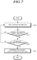
- FIG. 7 is a diagram for explaining a procedure for determining whether a subject vehicle can move to a side lane using distance information
- FIG. 8 is a diagram for explaining whether a subject vehicle can move to a side lane through comparison with relative distance information with a plurality of other vehicles;
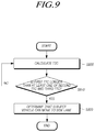
- FIG. 9 is a diagram for explaining an operation of determining whether a subject vehicle can move to a side lane using a time to collision (TTC).
- TTC time to collision
- FIG. 10 is a diagram for explaining an operation of re-determining whether a subject vehicle can move to a side lane based on a time to reach (TTR).
- TTR time to reach
- first, second, A, B, (a), (b) or the like may be used herein when describing components of the present disclosure.
- Each of these terminologies is not used to define an essence, order or sequence of a corresponding component but used merely to distinguish the corresponding component from other component(s).
- another structural element may “be connected to”, “be coupled to”, or “be in contact with” the structural elements as well as that the certain structural element is directly connected to or is in direct contact with another structural element
- FIG. 1 is a diagram illustrating the configuration of a driving lane changing apparatus according to an embodiment.
- a driving lane changing apparatus 100 may include a detector 110 that detects information about other vehicles traveling in a side lane or a subject lane based on received communication information or generated sensing information; a first determination unit 120 that determines whether a subject vehicle can move to the side lane based on relative distance information between the other vehicles and the subject vehicle; a first controller 130 that controls the subject vehicle to move adjacently to a line for distinguishing between the side lane and the subject lane when it is determined that the subject vehicle can move to the side lane; a second determination unit 140 that calculates longitudinal relative distance information between the subject vehicle and the other vehicles at a preset time point and re-determines whether the subject vehicle can move to the side lane based on the longitudinal relative distance information; and a second controller 150 that controls the subject vehicle to move to the side lane when it is re-determined that the subject vehicle can move to the side lane.
- FIG. 2 is a diagram illustrating an example for explaining the operation of a detector according to an embodiment.
- the detector 110 may detect relative distance information d 1 and d 2 and relative velocity information between a subject vehicle 210 and other vehicles 220 and 230 traveling in a side lane or a subject lane, based on communication information received from the outside and sensing information generated from a sensor that is included in the subject vehicle 210 to monitor the outside. In addition, the detector 110 may detect velocity information of the other vehicles 220 and 230 .
- the detector 110 may detect the relative distance information d 1 and d 2 and the relative velocity information between the subject vehicle 210 and the other vehicles 220 and 230 traveling in the side lane or the subject lane, based on communication information received directly from the other vehicles 220 and 230 . Specifically, the detector 110 may detect the relative distance information d 1 and d 2 and the relative velocity information between the subject vehicle 210 and the other vehicles 220 and 230 using position information and velocity information of the other vehicles 220 and 230 included in the communication information and position information and velocity information of the subject vehicle 210 which are known.
- the detector 110 may detect the relative distance information d 1 and d 2 and the relative velocity information between the subject vehicle 210 and the other vehicles 220 and 230 traveling in the side lane based on the sensing information generated by the sensor included in the subject vehicle 210 .
- the sensor may include at least one of a camera sensor, a radar sensor, and a lidar sensor, but the sensor type is not limited.
- the first determination unit 120 may determine whether the subject vehicle 210 can move to the side lane based on the relative distance information d 1 and d 2 between the subject vehicle 210 and the other vehicles 220 and 230 . Specifically, for example, when relative distance information between the subject vehicle 210 and a first other vehicle 220 is larger than at least one of relative distance information between the subject vehicle 210 and a second other vehicle 230 and relative distance information between the subject vehicle 210 and a preceding vehicle, it may be determined that the subject vehicle 210 can move to the side lane.
- the first determination unit 120 may determine that the subject vehicle 210 can move to the side lane when the relative distance information between the subject vehicle 210 and the first other vehicle 220 is larger than the relative distance information between the subject vehicle 210 and the second other vehicle 230 , and may determine that the subject vehicle 210 can move to the side lane when the relative distance information between the subject vehicle 210 and the first other vehicle 220 is larger than the relative distance information between the subject vehicle 210 and the preceding vehicle.
- the first determination unit 120 may determine that the subject vehicle 210 can move to the side lane.
- the first determination unit 120 may calculate a time to collision (TTC) based on the detected relative distance information and relative velocity information between the subject vehicle and the other vehicles.
- TTC time to collision
- the TTC may be calculated by dividing the relative distance information by the relative velocity information.
- the first determination unit 120 may determine whether the subject vehicle can move to the side lane based on the calculated TTC.
- the first determination unit 120 may determine that the subject vehicle 210 can move to the side lane.
- the first determination unit 120 may determine that the subject vehicle 210 can move to the side lane.
- the first determination unit 120 may determine that the subject vehicle 210 can move to the side lane.
- the first controller 130 may control the subject vehicle to move adjacently to a line for distinguishing between a side lane and a subject lane.
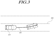
- FIG. 3 is a diagram illustrating an example for explaining the operation of the first controller according to an embodiment.
- the first controller 130 may set a path 330 through which a subject vehicle 310 moves adjacently to a line 320 for distinguishing between a side lane and a subject lane, and may control the subject vehicle 310 to travel along the set path 330 .
- the curvature of the path 330 may be set to be inversely proportional to the velocity of the subject vehicle 310 in consideration of stability, or the like.
- the subject vehicle moves adjacently to the line 320 , by which it is possible to induce deceleration of a first other vehicle which is another vehicle located behind the subject vehicle.
- the second determination unit 140 may determine whether longitudinal relative distance information between the subject vehicle and another vehicle is larger than a preset value at a predetermined time point, and may re-determine that the subject vehicle can move to a side lane when the longitudinal relative distance information is larger than the preset value. This provides an effect of improving safety in the case of a lane change.
- the other vehicle may refer to the above-described first other vehicle traveling in the side lane behind the subject vehicle, or may refer to the above-described second other vehicle.
- the second determination unit 140 may re-determine that the subject vehicle can move to the side lane.
- the predetermined number of times may be set in advance at predetermined time intervals based on a preset time point, or may be set in advance according to a relative position between the front wheel of the subject vehicle and the lane.
- a re-determination time point of the second determination unit 140 may be set in advance.
- the re-determination time point may be set in advance as a time point when the front wheel of the subject vehicle touches the line between the subject lane and the side lane.
- the time point set in advance may be set as a time point when the front wheel of the subject vehicle moves to a position spaced apart from the line by a predetermined distance.
- the second determination unit 140 may calculate a time to reach (TTR) using longitudinal relative distance information between the subject vehicle and the other vehicle and longitudinal velocity information with the other vehicle in a state in which the subject vehicle moves adjacent to the line, and may re-determine whether the subject vehicle can move to the side lane based on the calculated TTR.
- TTR time to reach
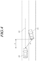
- FIG. 4 is a diagram illustrating an example for explaining the operation of the second determination unit according to an embodiment.
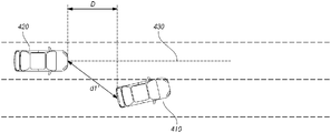
- the second determination unit 140 may calculate a TTR using longitudinal relative distance information calculated by a trigonometric function relationship of distance information between a subject vehicle 410 and a center line 430 of a side lane and relative distance information d 1 ′ between the subject vehicle 410 and another vehicle 420 .
- the TTR may refer to a value obtained by dividing the longitudinal relative distance information by the longitudinal velocity information.
- the TTR may be calculated using a longitudinal velocity V of the other vehicle 420 and a longitudinal distance D between the subject vehicle 410 and the other vehicle 420 , and may be determined according to the following Equation 1.
- Time to reach(TTR) longitudinal relative distance information( D )/longitudinal velocity( V ) [Equation 1]
- the distance between the subject vehicle 410 and the center line 430 of the side lane may be estimated by adding a half-length of the known width of the lane to a distance between the subject vehicle 410 and the side lane.
- the TTR may be calculated to be equal to or shorter than the TTC calculated by the first determination unit.
- the second determination unit 140 may determine that the subject vehicle can move to the side lane.
- the threshold time may be set in advance based on experimental data.
- the second determination unit 140 may determine that the subject vehicle can move to the side lane. That is, when it is determined that the other vehicle 420 is decelerated or the subject vehicle 410 is accelerated so that the subject vehicle 410 can safely perform a lane change, the second determination unit 140 may re-determine that the subject vehicle can move to the side lane.
- the second controller 150 may control the subject vehicle to move to the side lane.
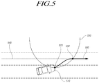
- FIG. 5 is a diagram illustrating an example for explaining the operation of the second controller according to an embodiment.
- the second controller 150 may first generate a center point 550 where a parabola 530 having a position point 520 of a subject vehicle 510 as a vertex while having a preset slope meets a center line 540 of a side lane.
- the second controller 150 may set a target path 560 moving from the position point 520 to the center point 550 , and may control the subject vehicle 510 to travel along the target path.
- the target path 560 may be set as a path through which the subject vehicle 510 can stably move from the position point 520 to the center point 550 .
- the target path 560 may be set by combining the parabola 530 having the position point 520 as the vertex and another parabola (not shown) having the center point 550 as a vertex while having the same slope as that of the parabola 530 .
- the second controller 150 may use a parabolic blending method in setting the target path 560 .
- the second controller 150 may control a movement path of the subject vehicle to be generated within an area where the above-described two parabolas overlap each other.
- the second controller 150 may track the position of the subject vehicle to calculate a movement path, may compare the calculated movement path with the set target path to calculate an error of the movement path, and may control the steering or velocity of the subject vehicle so that the calculated error of the movement path is reduced.
- the detection unit 110 may further detect the position of the subject vehicle, and the detected position of the subject vehicle may be stored for a predetermined time to calculate the movement path.
- the second controller 150 may use a parabola having a slope proportional to the velocity of the subject vehicle in setting the target path. That is, the second controller 150 may generate a center point where a parabola having a position point of the subject vehicle as a vertex while having a slope set in proportion to the velocity of the subject vehicle meets a center line of a side lane, and may set a target path moving from the position point to the center point. To this end, the detector 110 should further detect the velocity of the subject vehicle.
- the curvature of the target path may be gentle so that the stability of the subject vehicle can be ensured.
- the second controller 150 may control the subject vehicle to travel adjacent to the line for distinguishing between the side lane and the subject lane.
- the driving lane changing apparatus 100 may operate only the detector 110 , the second determination unit 140 , and the second controller 150 . In this case, only the detector 110 , the second determination unit 140 , and the second controller 150 are operated, so that the processing speed can be improved. Thus, it is possible to prevent a situation in which the subject vehicle may miss the timing to move to the side lane according to the processing speed.
- the operation of the driving lane changing apparatus 100 may be performed only when a lane change signal is detected.
- the lane change signal may refer to a signal indicating that the subject vehicle is about to move to the side lane, and may include a signal by a turn signal of the subject vehicle, a signal by an action that can be detected from a driver before the subject vehicle moves to the side lane, and the like.
- the operation of the driving lane changing apparatus 100 may be performed only when the lane change signal is detected under the situation that a lane keeping function is operated.
- the lane keeping function refers to a function to detect whether a subject vehicle has deviated from lines of a traveling lane.
- the lane change signal can be detected by the detector.
- the first determination unit may determine whether the subject vehicle can move to the side lane.
- the driving lane changing apparatus 100 may control the subject vehicle in accordance with a relationship with other vehicles traveling in the side lane or the velocity of the subject vehicle, thereby inducing the subject vehicle to safely move to the side lane.
- a driving lane changing apparatus may be operated considering further a preceding vehicle that is traveling in the same lane as that of the subject vehicle in order to induce the subject vehicle to safely move to the side lane.
- the detector of the driving lane changing apparatus may further detect relative distance information and relative velocity information between the subject vehicle and the preceding vehicle.
- the first determination unit may further calculate a third TTC using the relative distance information and the relative velocity information between the subject vehicle and the preceding vehicle, and may determine that the subject vehicle can move to the side lane when a first TTC that is a TTC with the first other vehicle is longer than the third TTC.
- the detector of the driving lane changing apparatus may further detect relative distance information and relative velocity information between the subject vehicle and the preceding vehicle.
- the first determination unit may further calculate a third TTC using the relative distance information and the relative velocity information between the subject vehicle and the preceding vehicle.
- the first determination unit may determine that the subject vehicle can move to the side lane.
- FIG. 6 is a flowchart illustrating a driving lane changing method according to an embodiment.
- the driving lane changing method may include detection operation S 600 of detecting information about other vehicles traveling in a side lane or a subject lane based on received communication information or generated sensing information; a first determination operation S 610 of determining whether a subject vehicle can move to the side lane based on relative distance information between the other vehicles and the subject vehicle; a first control operation S 620 of controlling the subject vehicle to move adjacently to a line for distinguishing between the side lane and the subject lane when it is determined that the subject vehicle can move to the side lane; a second determination operation S 630 of calculating longitudinal relative distance information between the subject vehicle and the other vehicles at a preset time point and re-determining whether the subject vehicle can move to the side lane based on the longitudinal relative distance information; and second control operation S 640 of controlling the subject vehicle to move to the side lane when it is re-determined that the subject vehicle can move to the side lane.
- Detection operation S 600 may detect the information about the other vehicles traveling in the side lane or the subject lane based on the communication information received from the outside or the sensing information generated from a sensor that is included in the subject vehicle to monitor the outside. For example, detection operation S 600 may detect relative distance information and relative velocity information.
- detection operation S 600 may detect relative distance information and relative velocity information between the subject vehicle and the other vehicles traveling in the side lane or the subject lane based on communication information received directly from the other vehicles. Specifically, for example, detection operation S 600 may detect the relative distance information and relative velocity information between the subject vehicle and the other vehicles using position information and velocity information of the other vehicles included in the communication information and position information and velocity information of the subject vehicle which are known.
- detection operation S 600 may detect the relative distance information and the relative velocity information between the subject vehicle and the other vehicles traveling in the side lane or the subject lane based on the sensing information generated by the sensor included in the subject vehicle.
- the sensor may include at least one of a camera sensor, a radar sensor, and a lidar sensor.
- FIG. 7 is a diagram for explaining a procedure for determining whether a subject vehicle can move to a side lane using distance information.
- the first determination operation determines whether the distance information is equal to or larger than a preset value in operation S 710 .
- the distance information is equal to or larger than the preset value, whether the corresponding distance information is continuously increased for a preset number of times is determined in operation S 720 .
- the first determination operation determines that the subject vehicle can move to the side lane in operation S 730 .
- the distance information refers to relative distance information between the subject vehicle and a first other vehicle.
- operation S 710 may be omitted as necessary.
- operation S 720 may be omitted.
- FIG. 7 may also be applied to second determination operation.
- the first determination operation determines whether the distance information is equal to or larger than the preset value in operation S 710 .
- the distance information is equal to or larger than the preset value
- whether the corresponding distance information is continuously increased for the preset number of times is determined in operation S 720 .
- the first determination operation determines that the subject vehicle can move to the side lane in operation S 730 .
- the distance information refers to longitudinal relative distance information between the subject vehicle and the first other vehicle. Operation S 710 or S 720 may be omitted as necessary.
- FIG. 8 is a diagram for explaining whether a subject vehicle can move to a side lane through comparison of relative distance information with a plurality of other vehicles.
- the first determination operation determines whether relative distance information with a first other vehicle is larger than at least one of relative distance information with a second other vehicle and relative distance information with a preceding vehicle in operation S 810 .
- the first determination operation may determine that the subject vehicle can move to the side lane when the relative distance information with the first other vehicle is larger than the relative distance information with the second other vehicle, and may determine that the subject vehicle can move to the side lane when the relative distance information between the subject vehicle and the first other vehicle is larger than the relative distance information between the subject vehicle and the preceding vehicle.
- the first determination operation may determine that the subject vehicle can move to the side lane when the relative distance information between the subject vehicle and the first other vehicle is larger than both the relative distance information between the subject vehicle and the second other vehicle and the relative distance information between the subject vehicle and the preceding vehicle.
- the first determination operation and the second determination operation may be performed using a TTC and a TTR.
- FIG. 9 is a diagram for explaining an operation of determining whether a subject vehicle can move to a side lane using a TTC.
- the first determination operation may calculate a TTC based on the detected relative distance information and relative velocity information with the other vehicles in operation S 900 .
- the TTC may be calculated by dividing the relative distance information by the relative velocity information.
- the first determination operation may determine whether the subject vehicle can move to the side lane based on the calculated TTC.
- the first determination operation determines whether a first TTC that is a TTC of the first other vehicle is longer than at least one of a second TTC that is a TTC of the second other vehicle and a third TTC that is a TTC of the preceding vehicle in operation S 910 .
- the first determination operation may determine that the subject vehicle can move to the side lane in operation S 920 .
- the first TTC calculated for the first other vehicle traveling behind the subject vehicle is longer than the third TTC calculated for the preceding vehicle traveling in front of the subject vehicle, the first determination operation may determine that the subject vehicle can move to the side lane in operation S 920 .
- the first determination operation may determine that the subject vehicle can move to the side lane in operation S 920 .
- the first control operation may control the subject vehicle to move adjacently to a line for distinguishing between the side lane and a subject lane.
- the first control operation S 620 may set a path through which the subject vehicle moves adjacent to the line for distinguishing between the side lane and the subject lane, and may control the subject vehicle to travel along the set path.
- the curvature of the path may be set to be inversely proportional to the velocity of the subject vehicle in consideration of stability, or the like.
- a re-determination operation may be performed based on a TTR.
- FIG. 10 is a diagram for explaining an operation of re-determining whether a subject vehicle can move to a side lane based on a TTR.
- the second determination operation further calculates longitudinal velocity information of the first other vehicle, and calculates a TTR based on longitudinal relative distance information and the longitudinal velocity information in operation S 1000 .
- the second determination operation may calculate the TTR using the longitudinal relative distance information between the subject vehicle and the other vehicles and the longitudinal velocity information at a preset time point (for example, a state in which the subject vehicle moves adjacent to the line), and may re-determine whether the subject vehicle can move to the side lane based on the calculated TTR.
- the second determination operation may calculate the TTR using longitudinal relative distance information calculated by a trigonometric function relationship of distance information between the subject vehicle and a center line of the side lane and relative distance information between the subject vehicle and the other vehicle.
- the TTR may refer to a value obtained by dividing the longitudinal relative distance information by the longitudinal velocity information.
- the distance between the subject vehicle and the center line of the side lane may be estimated by adding a half-length of the known width of the lane to a distance between the subject vehicle and the side lane.
- the TTR may be calculated to be equal to or shorter than the TTC calculated in the first determination operation.
- the second determination operation may determine whether the calculated TTR is longer than a preset threshold time in operation S 1010 .
- the threshold time may be set in advance based on experimental data.
- the second determination operation may determine whether the TTR calculated by a preset number of times is continuously increased in operation S 1020 . When it is determined that the TTR is continuously increased, the second determination operation may re-determine whether the subject vehicle can move to the side lane in operation S 1030 .
- the second control operation may control the subject vehicle to move to the side lane.
- the second control operation S 640 may generate a center point where a parabola having a position point of the subject vehicle as a vertex while having a preset slope meets the center line of the side lane.
- the second control operation may set a target path moving from the position point to the center point, and may control the subject vehicle to travel along the target path.
- the target path may be set as a path through which the subject vehicle can stably move from the position point to the center point.
- the target path may be set by combining the parabola having the position point as the vertex and another parabola having the center point as a vertex while having the same slope as that of the parabola.
- the second control operation may use a parabolic blending method in setting the target path.
- the second control operation may track the position of the subject vehicle to calculate a movement path, may compare the calculated movement path with the set target path to calculate an error of the movement path, and may control the steering or velocity of the subject vehicle so that the calculated error of the movement path is reduced.
- the detection operation may further detect the position of the subject vehicle, and the detected position of the subject vehicle may be stored for a predetermined time to calculate the movement path.
- the second control operation S 640 may use a parabola having a slope proportional to the velocity of the subject vehicle in setting the target path. That is, the second control operation may generate a center point where a parabola having a position point of the subject vehicle as a vertex while having a slope set in proportion to the velocity of the subject vehicle meets the center line of the side lane, and may set a target path moving from the position point to the center ponit. To this end, the detection operation should further detect the velocity of the subject vehicle.
- the curvature of the target path may be gentle so that the stability of the subject vehicle can be ensured.
- the operation of the driving lane changing method may be performed when a lane change signal is detected.
- the lane change signal may refer to a signal indicating that the subject vehicle is about to move to the side lane.
- the lane change signal may include a signal by a turn signal of the subject vehicle, a signal by an action that can be detected from a driver before the subject vehicle moves to the side lane, and the like.
- the lane change signal may be detected by the detector.
- the operation of the driving lane changing method may be performed only when a lane keeping function is operated.
- whether the subject vehicle can move to the side lane may be determined through the first determination operation.
- the driving lane changing method may perform all the operations performed by the lane changing apparatus described with reference to FIGS. 1 to 10 .
Landscapes
- Engineering & Computer Science (AREA)
- Automation & Control Theory (AREA)
- Transportation (AREA)
- Mechanical Engineering (AREA)
- Physics & Mathematics (AREA)
- General Physics & Mathematics (AREA)
- Mathematical Physics (AREA)
- Human Computer Interaction (AREA)
- Aviation & Aerospace Engineering (AREA)
- Radar, Positioning & Navigation (AREA)
- Remote Sensing (AREA)
- Traffic Control Systems (AREA)
Abstract
Description
Time to reach(TTR)=longitudinal relative distance information(D)/longitudinal velocity(V) [Equation 1]
Claims (9)
Applications Claiming Priority (2)
| Application Number | Priority Date | Filing Date | Title |
|---|---|---|---|
| KR1020160144371A KR102629625B1 (en) | 2016-11-01 | 2016-11-01 | Driving lane changing apparatus and driving lane changing method |
| KR10-2016-0144371 | 2016-11-01 |
Publications (2)
| Publication Number | Publication Date |
|---|---|
| US20180118215A1 US20180118215A1 (en) | 2018-05-03 |
| US10850737B2 true US10850737B2 (en) | 2020-12-01 |
Family
ID=61912476
Family Applications (1)
| Application Number | Title | Priority Date | Filing Date |
|---|---|---|---|
| US15/800,467 Active 2038-12-28 US10850737B2 (en) | 2016-11-01 | 2017-11-01 | Driving lane changing apparatus and driving lane changing method |
Country Status (4)
| Country | Link |
|---|---|
| US (1) | US10850737B2 (en) |
| KR (1) | KR102629625B1 (en) |
| CN (1) | CN108016443A (en) |
| DE (1) | DE102017219456A1 (en) |
Cited By (3)
| Publication number | Priority date | Publication date | Assignee | Title |
|---|---|---|---|---|
| US11119491B2 (en) * | 2019-02-07 | 2021-09-14 | Ford Global Technologies, Llc | Vehicle steering control |
| US20210354698A1 (en) * | 2020-04-21 | 2021-11-18 | Mando Corporation | Apparatus for assisting driving and method thereof |
| US11227498B2 (en) * | 2018-06-08 | 2022-01-18 | Toyota Jidosha Kabushiki Kaisha | Lane change assist system, lane change assist device, and lane change assist method |
Families Citing this family (9)
| Publication number | Priority date | Publication date | Assignee | Title |
|---|---|---|---|---|
| US10814913B2 (en) * | 2017-04-12 | 2020-10-27 | Toyota Jidosha Kabushiki Kaisha | Lane change assist apparatus for vehicle |
| US11142246B2 (en) | 2017-04-12 | 2021-10-12 | Toyota Jidosha Kabushiki Kaisha | Lane change assist apparatus for vehicle |
| JP6627821B2 (en) | 2017-06-06 | 2020-01-08 | トヨタ自動車株式会社 | Lane change support device |
| CN109540161A (en) * | 2018-11-08 | 2019-03-29 | 东软睿驰汽车技术(沈阳)有限公司 | A kind of air navigation aid and device of vehicle |
| JP7022680B2 (en) * | 2018-12-27 | 2022-02-18 | 本田技研工業株式会社 | Vehicle control device |
| CN109878523A (en) * | 2019-03-08 | 2019-06-14 | 北京领骏科技有限公司 | A kind of automatic driving vehicle lane changing control method and device |
| CN110194169B (en) * | 2019-05-31 | 2021-09-17 | 惠州华阳通用智慧车载系统开发有限公司 | Vehicle lane change assisting method |
| CN112634627B (en) * | 2019-10-08 | 2023-03-10 | 宁波吉利汽车研究开发有限公司 | Lane changing method and device in high-speed cruising state and automobile |
| CN111332298B (en) * | 2020-02-19 | 2021-08-31 | 北京百度网讯科技有限公司 | Method, device and equipment for determining travelable area and storage medium |
Citations (1)
| Publication number | Priority date | Publication date | Assignee | Title |
|---|---|---|---|---|
| US20050256630A1 (en) * | 2004-05-17 | 2005-11-17 | Nissan Motor Co., Ltd. | Lane change assist system |
Family Cites Families (12)
| Publication number | Priority date | Publication date | Assignee | Title |
|---|---|---|---|---|
| JP3132361B2 (en) * | 1995-03-17 | 2001-02-05 | トヨタ自動車株式会社 | Automotive radar equipment |
| JP4366419B2 (en) * | 2007-09-27 | 2009-11-18 | 株式会社日立製作所 | Driving support device |
| KR20120056158A (en) * | 2010-11-24 | 2012-06-01 | 현대자동차주식회사 | Method for lane active change |
| DE102011106746B4 (en) * | 2011-06-28 | 2015-04-09 | Deutsches Zentrum für Luft- und Raumfahrt e.V. | Lane change assistance system |
| JP5743022B2 (en) * | 2012-03-12 | 2015-07-01 | 日産自動車株式会社 | Travel control device |
| DE102012006882A1 (en) * | 2012-04-03 | 2012-11-08 | Daimler Ag | Method for assisting driver of motor vehicle during contriving into lane, involves transmitting movement data comprising information about movement of vehicle to stationary measuring device for enabling convergence of motor vehicle |
| KR101987636B1 (en) * | 2012-11-09 | 2019-09-30 | 현대모비스 주식회사 | Control method for collision avoidance of vehicle and Apparatus for collision avoidance of vehicle implementing the same |
| KR101362706B1 (en) * | 2012-11-23 | 2014-02-24 | 현대엠엔소프트 주식회사 | Method for runnability ensuring the vhicle's straight in complex lanes system |
| KR101439017B1 (en) * | 2013-04-11 | 2014-10-30 | 현대자동차주식회사 | System for controlling change of lane |
| JP6052424B2 (en) * | 2013-10-11 | 2016-12-27 | 日産自動車株式会社 | Travel control device and travel control method |
| KR101541483B1 (en) * | 2014-01-03 | 2015-08-03 | 현대모비스(주) | System for monitoring change of a traffic lane andcontrol method thereof |
| US9473067B2 (en) | 2014-04-11 | 2016-10-18 | Qualcomm Incorporated | Reducing mismatch caused by power/ground routing in multi-core VCO structure |
-
2016
- 2016-11-01 KR KR1020160144371A patent/KR102629625B1/en active IP Right Grant
-
2017
- 2017-10-30 DE DE102017219456.1A patent/DE102017219456A1/en active Pending
- 2017-11-01 US US15/800,467 patent/US10850737B2/en active Active
- 2017-11-01 CN CN201711058021.9A patent/CN108016443A/en active Pending
Patent Citations (1)
| Publication number | Priority date | Publication date | Assignee | Title |
|---|---|---|---|---|
| US20050256630A1 (en) * | 2004-05-17 | 2005-11-17 | Nissan Motor Co., Ltd. | Lane change assist system |
Cited By (4)
| Publication number | Priority date | Publication date | Assignee | Title |
|---|---|---|---|---|
| US11227498B2 (en) * | 2018-06-08 | 2022-01-18 | Toyota Jidosha Kabushiki Kaisha | Lane change assist system, lane change assist device, and lane change assist method |
| US11119491B2 (en) * | 2019-02-07 | 2021-09-14 | Ford Global Technologies, Llc | Vehicle steering control |
| US20210354698A1 (en) * | 2020-04-21 | 2021-11-18 | Mando Corporation | Apparatus for assisting driving and method thereof |
| US11977147B2 (en) * | 2020-04-21 | 2024-05-07 | Hl Klemove Corp. | Apparatus for assisting driving and method thereof |
Also Published As
| Publication number | Publication date |
|---|---|
| US20180118215A1 (en) | 2018-05-03 |
| CN108016443A (en) | 2018-05-11 |
| KR20180047717A (en) | 2018-05-10 |
| KR102629625B1 (en) | 2024-01-29 |
| DE102017219456A1 (en) | 2018-05-03 |
Similar Documents
| Publication | Publication Date | Title |
|---|---|---|
| US10850737B2 (en) | Driving lane changing apparatus and driving lane changing method | |
| US11364901B2 (en) | Driving support apparatus | |
| CN107284454B (en) | Anti-collision device and anti-collision method | |
| JP5929870B2 (en) | Target detection device | |
| EP3221856B1 (en) | Lane assistance system responsive to extremely fast approaching vehicles | |
| US9896073B2 (en) | Method and device for carrying out collision-avoiding measures | |
| KR102374921B1 (en) | Vehicle Control System and Method Thereof | |
| US20170372150A1 (en) | Processing of Sensor Data for a Driver Assistance System | |
| US10053065B2 (en) | Automatic rear braking | |
| WO2010064282A1 (en) | Pre-crash safety system | |
| CN104865579A (en) | Vehicle-installed Obstacle Detection Apparatus Having Function For Judging Motion Condition Of Detected Object | |
| KR20160080613A (en) | Apparatuses and Methods for line changing | |
| WO2015097511A1 (en) | Vehicle surrounding situation estimation device | |
| JP3918656B2 (en) | Obstacle detection device for vehicle | |
| JP2009536132A (en) | Vehicle speed control method in complex traffic situations | |
| JP6358017B2 (en) | Driving assistance device | |
| CN106470884B (en) | Determination of vehicle state and driver assistance while driving a vehicle | |
| JP2016197464A (en) | Method for monitoring traffic and control unit | |
| WO2016017494A1 (en) | Driving assistance apparatus | |
| JP6589840B2 (en) | Driving assistance device | |
| EP3576069B1 (en) | Method for a host vehicle to assess risk of overtaking a target vehicle on a pedestrian crossing | |
| JP2017182768A (en) | Collision prevention apparatus | |
| KR102653169B1 (en) | Apparatus and method for controlling a Rear Cross Traffic Alert | |
| US20160116584A1 (en) | Object detection apparatus | |
| KR102352931B1 (en) | Safety apparatus and safety method for risk of collision |
Legal Events
| Date | Code | Title | Description |
|---|---|---|---|
| AS | Assignment |
Owner name: MANDO CORPORATION, KOREA, REPUBLIC OF Free format text: ASSIGNMENT OF ASSIGNORS INTEREST;ASSIGNOR:KIM, BYUNG JOO;REEL/FRAME:044006/0828 Effective date: 20171101 |
|
| FEPP | Fee payment procedure |
Free format text: ENTITY STATUS SET TO UNDISCOUNTED (ORIGINAL EVENT CODE: BIG.); ENTITY STATUS OF PATENT OWNER: LARGE ENTITY |
|
| STPP | Information on status: patent application and granting procedure in general |
Free format text: DOCKETED NEW CASE - READY FOR EXAMINATION |
|
| STPP | Information on status: patent application and granting procedure in general |
Free format text: NON FINAL ACTION MAILED |
|
| STPP | Information on status: patent application and granting procedure in general |
Free format text: PUBLICATIONS -- ISSUE FEE PAYMENT RECEIVED |
|
| STCF | Information on status: patent grant |
Free format text: PATENTED CASE |
|
| AS | Assignment |
Owner name: MANDO MOBILITY SOLUTIONS CORPORATION, KOREA, REPUBLIC OF Free format text: ASSIGNMENT OF ASSIGNORS INTEREST;ASSIGNOR:MANDO CORPORATION;REEL/FRAME:058042/0372 Effective date: 20211026 |
|
| AS | Assignment |
Owner name: HL KLEMOVE CORP., KOREA, REPUBLIC OF Free format text: MERGER;ASSIGNOR:MANDO MOBILITY SOLUTIONS CORPORATION;REEL/FRAME:060809/0652 Effective date: 20211202 |
|
| MAFP | Maintenance fee payment |
Free format text: PAYMENT OF MAINTENANCE FEE, 4TH YEAR, LARGE ENTITY (ORIGINAL EVENT CODE: M1551); ENTITY STATUS OF PATENT OWNER: LARGE ENTITY Year of fee payment: 4 |