US10798761B2 - Method for establishing protocol data unit session in communication system - Google Patents
Method for establishing protocol data unit session in communication system Download PDFInfo
- Publication number
- US10798761B2 US10798761B2 US16/003,530 US201816003530A US10798761B2 US 10798761 B2 US10798761 B2 US 10798761B2 US 201816003530 A US201816003530 A US 201816003530A US 10798761 B2 US10798761 B2 US 10798761B2
- Authority
- US
- United States
- Prior art keywords
- pdu sessions
- pdu
- service
- pdu session
- establishing
- Prior art date
- Legal status (The legal status is an assumption and is not a legal conclusion. Google has not performed a legal analysis and makes no representation as to the accuracy of the status listed.)
- Active, expires
Links
Images


Classifications
-
- H—ELECTRICITY
- H04—ELECTRIC COMMUNICATION TECHNIQUE
- H04W—WIRELESS COMMUNICATION NETWORKS
- H04W76/00—Connection management
- H04W76/10—Connection setup
- H04W76/12—Setup of transport tunnels
-
- H—ELECTRICITY
- H04—ELECTRIC COMMUNICATION TECHNIQUE
- H04L—TRANSMISSION OF DIGITAL INFORMATION, e.g. TELEGRAPHIC COMMUNICATION
- H04L67/00—Network arrangements or protocols for supporting network services or applications
- H04L67/14—Session management
-
- H—ELECTRICITY
- H04—ELECTRIC COMMUNICATION TECHNIQUE
- H04L—TRANSMISSION OF DIGITAL INFORMATION, e.g. TELEGRAPHIC COMMUNICATION
- H04L69/00—Network arrangements, protocols or services independent of the application payload and not provided for in the other groups of this subclass
- H04L69/30—Definitions, standards or architectural aspects of layered protocol stacks
- H04L69/32—Architecture of open systems interconnection [OSI] 7-layer type protocol stacks, e.g. the interfaces between the data link level and the physical level
- H04L69/322—Intralayer communication protocols among peer entities or protocol data unit [PDU] definitions
-
- H—ELECTRICITY
- H04—ELECTRIC COMMUNICATION TECHNIQUE
- H04L—TRANSMISSION OF DIGITAL INFORMATION, e.g. TELEGRAPHIC COMMUNICATION
- H04L67/00—Network arrangements or protocols for supporting network services or applications
- H04L67/14—Session management
- H04L67/141—Setup of application sessions
-
- H—ELECTRICITY
- H04—ELECTRIC COMMUNICATION TECHNIQUE
- H04L—TRANSMISSION OF DIGITAL INFORMATION, e.g. TELEGRAPHIC COMMUNICATION
- H04L67/00—Network arrangements or protocols for supporting network services or applications
- H04L67/50—Network services
- H04L67/56—Provisioning of proxy services
-
- H—ELECTRICITY
- H04—ELECTRIC COMMUNICATION TECHNIQUE
- H04W—WIRELESS COMMUNICATION NETWORKS
- H04W48/00—Access restriction; Network selection; Access point selection
- H04W48/18—Selecting a network or a communication service
-
- H—ELECTRICITY
- H04—ELECTRIC COMMUNICATION TECHNIQUE
- H04W—WIRELESS COMMUNICATION NETWORKS
- H04W76/00—Connection management
- H04W76/10—Connection setup
- H04W76/15—Setup of multiple wireless link connections
-
- H—ELECTRICITY
- H04—ELECTRIC COMMUNICATION TECHNIQUE
- H04W—WIRELESS COMMUNICATION NETWORKS
- H04W12/00—Security arrangements; Authentication; Protecting privacy or anonymity
- H04W12/06—Authentication
-
- H—ELECTRICITY
- H04—ELECTRIC COMMUNICATION TECHNIQUE
- H04W—WIRELESS COMMUNICATION NETWORKS
- H04W4/00—Services specially adapted for wireless communication networks; Facilities therefor
- H04W4/30—Services specially adapted for particular environments, situations or purposes
- H04W4/40—Services specially adapted for particular environments, situations or purposes for vehicles, e.g. vehicle-to-pedestrians [V2P]
-
- H—ELECTRICITY
- H04—ELECTRIC COMMUNICATION TECHNIQUE
- H04W—WIRELESS COMMUNICATION NETWORKS
- H04W76/00—Connection management
- H04W76/30—Connection release
- H04W76/34—Selective release of ongoing connections
Definitions
- the disclosure relates to methods for establishing a protocol data unit (PDU) session in a communication system, and more specifically, to methods for establishing a plurality of PDU sessions.
- PDU protocol data unit
- the 5G communication system or pre-5G communication system is called the beyond 4G network communication system or post LTE system.
- 5G communication systems are considered to be implemented on ultra high frequency bands (mmWave), such as, e.g., 60 GHz.
- mmWave ultra high frequency bands
- MIMO massive multi-input multi-output
- FD-MIMO full dimensional MIMO
- array antenna analog beamforming
- large scale antenna large scale antenna
- 5G communication system also being developed are various technologies for the 5G communication system to have an enhanced network, such as evolved or advanced small cell, cloud radio access network (cloud RAN), ultra-dense network, device-to-device (D2D) communication, wireless backhaul, moving network, cooperative communication, coordinated multi-point (CoMP), and reception interference cancellation.
- cloud RAN cloud radio access network
- D2D device-to-device
- CoMP coordinated multi-point
- 5G network technology is a successor to 4G LTE mobile communication technology and seeks an end-to-end (E2E) system in which all targets are highly integrated over a network providing access in a wired or other various schemes.
- E2E end-to-end
- ITU-R, ITU-T, NGMN, 3GPP or other standardization organizations are designing brand-new clean slate-type systems and network architectures to implement wireless and wired network technology featuring high performance, low latency, and high availability.
- a most prominent feature of 5G networks lies in adopting network slicing for radio access networks (RANs) and core networks (CNs). This is intended for bundling up network resources and network functions into a single independent slice depending on individual services, allowing for application of network system function and resource isolation, customization, independent management and orchestration to mobile communication network architectures.
- RANs radio access networks
- CNs core networks
- the use of such network slicing enables offering 5G services in an independent and flexible way by selecting and combining 5G system network functions according to services, users, business models, or such references.
- the slice over a 5G network provides customized 5G network services by combining control plane (CP) and user plane (UP) network functions for 5G services necessary for a particular service over a core network and a radio access network.
- CP control plane
- UP user plane
- a method for establishing a plurality of PDU sessions capable of reducing duplicate signaling processes, minimizing the number of interactions between a user equipment (UE) and a CN, and establishing a PDU session, which is sensitive to latency as are critical (CriC) services, as soon as possible.
- a method for establishing a plurality of PDU sessions capable of reducing latency in exchanging non-access stratum (NAS) messages between a UE and a core access and mobility management function (AMF) when the AMF is changed when supporting connectivity between the UE and the AMF.
- NAS non-access stratum
- AMF core access and mobility management function
- a method for establishing a plurality of protocol data unit (PDU) sessions between a user equipment (UE) and a data network (DN) by the UE comprises transmitting a message to establish the plurality of PDU sessions to at least one network function (NF) of a plurality of NFs, exchanging a signal to establish the plurality of PDU sessions among the UE, a radio access network (RAN), and the plurality of NFs based on the message, and establishing the plurality of PDU sessions between the UE and the DN according to predetermined priority and based on the signal, wherein each of the plurality of PDU sessions corresponds to a network slice (NS) for a particular service, wherein the message includes information about the particular service corresponding to the plurality of PDU sessions, and wherein the priority is determined based on the information about the particular service.
- NF network function
- a method for establishing, by a UE, a plurality of PDU sessions between the UE and a data network (DN) in a system including a core network (CN) including a plurality of NFs, the UE, a RAN, the DN, and a proxy-based first NF connected to each of the NFs and the RAN comprises performing first sticky connection between the RAN and the proxy and second sticky connection between the proxy and the first NF and transmitting a message to establish the plurality of PDU sessions between the UE and the DN using the first sticky connection and the second sticky connection between the RAN and the first NF.
- NS network slice
- various functions described below can be implemented or supported by one or more computer programs, each of which is formed from computer readable program code and embodied in a computer readable medium.
- application and “program” refer to one or more computer programs, software components, sets of instructions, procedures, functions, objects, classes, instances, related data, or a portion thereof adapted for implementation in a suitable computer readable program code.
- computer readable program code includes any type of computer code, including source code, object code, and executable code.
- computer readable medium includes any type of medium capable of being accessed by a computer, such as read only memory (ROM), random access memory (RAM), a hard disk drive, a compact disc (CD), a digital video disc (DVD), or any other type of memory.
- ROM read only memory
- RAM random access memory
- CD compact disc
- DVD digital video disc
- a “non-transitory” computer readable medium excludes wired, wireless, optical, or other communication links that transport transitory electrical or other signals.
- a non-transitory computer readable medium includes media where data can be permanently stored and media where data can be stored and later overwritten, such as a rewritable optical disc or an erasable memory device.
- FIGS. 1 and 2 respectively, illustrate a 5G system architecture and a non-roaming 5G system architecture represented with reference points;
- FIGS. 3A and 3B illustrate a UE-requested single PDU session establishment for a non-roaming scenario
- FIG. 4 illustrates a non-roaming 5G system architecture for a UE simultaneously accessing three DNs using three PDU sessions
- FIGS. 5A and 5B illustrate a method for establishing three PDU sessions
- FIG. 6 illustrates a 5G system architecture for establishing a plurality of PDU sessions using an indicator (iMess) representing a request for establishing a plurality of PDU sessions in a 5G system;
- iMess an indicator representing a request for establishing a plurality of PDU sessions in a 5G system
- FIGS. 7A, 7B, and 7C illustrate a method for establishing a plurality of PDU sessions using an indicator (iMess) representing a request for establishing a plurality of PDU sessions in a 5G system;
- iMess an indicator representing a request for establishing a plurality of PDU sessions in a 5G system
- FIG. 8 illustrates various examples of an iMess for establishing a plurality of PDU sessions corresponding to a CriC service
- FIG. 9 illustrates an enhancement achieved by a method for establishing a plurality of PDU sessions based on an iMess as compared with a legacy method for establishing a plurality of PDU sessions;
- FIG. 10 illustrates a flowchart of a migration procedure of an NF based on a database as per a scheme
- FIGS. 11 and 12 illustrate various examples of implementing a proxy-based NF
- FIG. 13 illustrates compatibility between a temporary ID (temp ID) architecture according to an embodiment of the present disclosure
- FIG. 14 illustrates a flowchart of a procedure for a proxy NF-based NF migration supporting scheme
- FIG. 15 illustrates various examples of managing the constancy of the RAN-proxy-AMF connection (i.e., N2AP connection) based on the characteristics of the network slice (NS);
- FIGS. 16A and 16B illustrate operations on a slice that does not maintain N2AP connection
- FIG. 17 illustrates a flowchart of a procedure for database-based load balancing supporting
- FIG. 18 illustrates a flowchart of a procedure for random selection-based load balancing supporting
- FIG. 19 illustrates a graph of a latency ratio of the conventional solution and an embodiment of the disclosure that has been measured while prolonging the mean occurrence period of the NAS message;
- FIG. 20 illustrates an example of a configuration of a UE in which a method for establishing a plurality of PDU sessions is implemented according to an embodiment
- FIGS. 21 and 22 illustrate flowcharts of a method for establishing a plurality of PDU sessions according to an embodiment.
- FIGS. 1 through 22 discussed below, and the various embodiments used to describe the principles of the present disclosure in this patent document are by way of illustration only and should not be construed in any way to limit the scope of the disclosure. Those skilled in the art will understand that the principles of the present disclosure may be implemented in any suitably arranged system or device.
- a “component surface” includes one or more component surfaces.
- first and ‘second’ may be used to denote various components, but the components are not limited by the terms. The terms are used only to distinguish one component from another. For example, a first component may be denoted a second component, and vice versa without departing from the scope of the disclosure.
- the term “and/or” may denote a combination(s) of a plurality of related items as listed or any of the items.
- an electronic device as disclosed herein may include a communication function.
- the electronic device may be a smartphone, a tablet PC, a personal computer (PC), a mobile phone, a video phone, an e-book reader, a desktop PC, a laptop PC, a netbook PC, a personal digital assistant (PDA), a portable multimedia player (PMP), an MP3 player, a mobile medical device, a camera, a wearable device (e.g., a head-mounted device (HMD)), electronic clothes, an electronic bracelet, an electronic necklace, an electronic appcessory, an electronic tattoo, or a smart watch.
- PDA personal digital assistant
- PMP portable multimedia player
- MP3 player MP3 player
- the electronic device may be a smart home appliance with a communication function.
- the smart home appliance may be a television, a digital video disk (DVD) player, an audio player, a refrigerator, an air conditioner, a vacuum cleaner, an oven, a microwave oven, a washer, a drier, an air cleaner, a set-top box, a TV box (e.g., Samsung HomeSyncTM, Apple TVTM, or Google TVTM), a gaming console, an electronic dictionary, a camcorder, or an electronic picture frame.
- DVD digital video disk
- the electronic device may be a medical device (e.g., magnetic resource angiography (MRA) device, a magnetic resource imaging (MRI) device, a computed tomography (CT) device, an imaging device, or an ultrasonic device), a navigation device, a global positioning system (GPS) receiver, an event data recorder (EDR), a flight data recorder (FDR), an automotive infotainment device, an sailing electronic device (e.g., a sailing navigation device, a gyroscope, or a compass), an aviation electronic device, a security device, or a robot for home or industry.
- MRA magnetic resource angiography
- MRI magnetic resource imaging
- CT computed tomography
- FDR flight data recorder
- automotive infotainment device e.g., a sailing navigation device, a gyroscope, or a compass
- an aviation electronic device e.g., a security device, or a robot for home or industry.
- the electronic device may be a piece of furniture with a communication function, part of a building/structure, an electronic board, an electronic signature receiving device, a projector, or various measurement devices (e.g., devices for measuring water, electricity, gas, or electromagnetic waves).
- various measurement devices e.g., devices for measuring water, electricity, gas, or electromagnetic waves.
- an electronic device may be a combination of the above-listed devices. It should be appreciated by one of ordinary skill in the art that the electronic device is not limited to the above-described devices.
- An embodiment may be intended for simultaneously operating several types of eMBB services such as instant messaging, video streaming, or social media services. Such embodiment may work when exchanging universal subscriber identification module (USIM) cards or when receiving back 5G services leaving out of non-service areas, e.g., a subway station. In this case, the mobile device may boot up within a shorter time by reducing the PDU session establishment of multiple background applications.
- Another embodiment involves using a mobile device that receives multiple eMBB services and one V2X CriC service in a car that is moving.
- the UE Upon passing through a non-service area, such as a tunnel, or resuming the mobile device in the car, e.g., for exchanging batteries, the UE is allowed to receive a V2X service including information related to the traveling route earlier than the other services.
- a non-service area such as a tunnel, or resuming the mobile device in the car, e.g., for exchanging batteries
- the UE Upon passing through a non-service area, such as a tunnel, or resuming the mobile device in the car, e.g., for ex
- FIGS. 1 and 2 respectively, illustrate a 5G system architecture and a non-roaming 5G system architecture represented with reference points.
- a 5G system architecture may include a user equipment (UE), a radio access network (RAN), and a plurality of network functions (NFs) inside a data network (DN) and a core network (CN) which are network components.
- UE user equipment
- RAN radio access network
- NFs network functions
- DN data network
- CN core network
- functions, connection points, or protocols may be defined for the plurality of NFs.
- the 5G system structure may be shown with reference points indicating service-based interfaces corresponding to the NFs and reference points indicating interactions present among the NFs.
- the plurality of NFs may include an authentication server function (AUSF), a core access and mobility management function (AMF), a network exposure function (NEF), a network function repository function (NRF), a policy control function (PCF), a session management function (SMF), a unified data management (UDM), a user plane function (UPF), and an application function (AF).
- AUSF authentication server function
- AMF core access and mobility management function
- NEF network exposure function
- NRF network function repository function
- PCF policy control function
- SMF session management function
- UDM unified data management
- UPF user plane function
- AF application function
- the AMF 12 a or 12 b , the SMF 14 a or 14 b , the PCF 15 a or 15 b , and the UPF 13 a or 13 b are referred to as protocol data units requested by the UE (“UE-requested PDUs”).
- the plurality of NFs may play a core role in managing UE 10 a
- the plurality of reference points may include an NAMF 12 a or 12 b (service-based interface exhibited by AMF( 12 a , 12 b )), an NSMF 14 a or 14 b (service-based interface exhibited by SMF( 14 a , 14 b )), an NNEF (service-based interface exhibited by NEF( 1 )), an NPCF 15 a or 15 b (service-based interface exhibited by PCF( 15 a , 15 b )), an NUDM 16 a or 16 b (service-based interface exhibited by UDM( 16 a , 16 b )), an NAF 18 a or 18 b (service-based interface exhibited by AF( 18 a , 18 b )), an NNRF (service-based interface exhibited by NRF( 2 )), an NAUSF 19 a or 19 b (service-based interface exhibited by AUSF( 19 a , 19 b )), an N1 (reference point between the UE(
- the UE 10 a or 10 b user equipment—may be implemented in various forms.
- the UE may be, e.g., a mobile phone, a smartphone, a laptop computer, a digital broadcast terminal, a portable digital assistant (PDA), a portable media player (PMP), or a navigation device.
- the UE 10 a or 10 b may include an electronic device.
- the reference point between the UE 10 a or 10 b and the AMF 12 a or 12 b is defined as N1.
- the (R)AN 11 a or 11 b represents a base station that uses new radio access technology (RAT).
- the AN 11 a or 11 b may be a typical base station adopting non-3GPP access technology, e.g., wireless-fidelity (Wi-Fi).
- Wi-Fi wireless-fidelity
- the reference point between the AN 11 a or 11 b and the AMF 12 a or 12 b is defined as N2, and the reference point between the AN and the UPF 13 a or 13 b is defined as N3.
- the DN 17 a or 17 b may deliver PDUs, which are to be sent on downlink, to the UPF 13 a or 13 b or receive PDUs from the UE 10 a or 10 b via the UPF 13 a or 13 b .
- the reference point between the DN 17 a or 17 b and the UPF 13 a or 13 b is defined as NG 6 .
- the AMF 12 a or 12 b provides access and mobility management functionality to manage the access and mobility independently of access technology, i.e., per UE 10 a or 10 b .
- the reference point between the AMF 12 a or 12 b and the UE 10 a or 10 b is defined as N1.
- the reference point between the AMF 12 a or 12 b and the AN is defined as N2.
- the reference point between the AMF 12 a or 12 b and the UDM 16 a or 16 b is defined as N8.
- the reference point between the AMF 12 a or 12 b and the AUSF 19 a or 19 b is defined as N12.
- the reference point between the AMF 12 a or 12 b and the SMF 14 a or 14 b is defined as N11.
- the SMF 14 a or 14 b provides session management functionality in which, where one UE 10 a or 10 b has several sessions, a different SMF 14 a or 14 b is assigned per session to manage the sessions.
- the UPF 13 a or 13 b is set up using control signal information produced by the SMF 14 a or 14 b .
- the NG 4 reference point is defined for the UPF 13 a or 13 b to be able to report a state of the NG 4 reference point to the SMF 14 a or 14 b .
- the reference point between the SMF 14 a or 14 b and the AMF 12 a or 12 b is defined as N11.
- the reference point between the SMF 14 a or 14 b and the UDM 16 a or 16 b is defined as N10.
- the reference point between the SMF 14 a or 14 b and the PCF 15 a or 15 b is defined as N7.
- the reference point between the SMF 14 a or 14 b and the AMF 12 a or 12 b is defined as N11.
- each UE 10 a or 10 b may connect to one AMF 12 a or 12 b .
- the SMF 14 a or 14 b one UE 10 a or 10 b may have several sessions, and thus, a different SMF 14 a or 14 b may be provided for each session.
- the AF 18 a or 18 b may provide information about the flow of packets to the PCF 15 a or 15 b responsible for policy control to ensure the quality of service (QoS), and based thereupon, the PCF 15 a or 15 b may determine a policy for, e.g., session management or mobility management and deliver the policy to the AMF 12 a or 12 b or the SMF 14 a or 14 b , achieving mobility, session, and QoS management in a proper way.
- the reference point between the AF 18 a or 18 b and the PCF 15 a or 15 b is defined as N5.
- the AUSF 19 a or 19 b stores data for authenticating the UE 10 a or 10 b
- the UDM 16 a or 16 b stores the user's subscription data or policy data.
- the reference point between the AUSF 19 a or 19 b and the UDM 16 a or 16 b is defined as N13.
- the reference point between the AUSF 19 a or 19 b and the AMF 12 a or 12 b is defined as N12.
- the reference point between the UDM 16 a or 16 b and the AMF 12 a or 12 b is defined as N8.
- the reference point between the UDM 16 a or 16 b and the SMF 14 a or 14 b is defined as N10.
- the CP functions may include various functions to control the network and UE.
- the UE 10 a or 10 b , the (R)AN 11 a or 11 b , the UPF 13 a or 13 b , the AMF 12 a or 12 b , the AF 18 a or 18 b , and the DN 17 a or 17 b in charge of mobility management functionality and the SMF 14 a or 14 b in charge of session management functionality are two independent functions and included in the CP functions.
- the 5G system of FIG. 2 may lack the NEF 1 and the NRF 2 of FIG. 1 because such NFs may interwork with the NFs of FIG. 2 as necessary.
- the operations among the UE 10 a or 10 b , the (R)AN 11 a or 11 b , the AMF 12 a or 12 b , the UPF 13 a or 13 b , the SMF 14 a or 14 b , the PCF 15 a or 15 b , the UDM 16 a or 16 b , and the DN 17 a or 17 b in the 5G system shown in FIG. 2 are sequentially described below.
- Fig. illustrates a UE-requested single PDU session establishment for a non-roaming scenario.
- the 5G system supports a PDU connection service, i.e., a service for exchanging PDUs between the UE 10 a or 10 b and the DN 17 a or 17 b identified by the DNN.
- a PDU connection service i.e., a service for exchanging PDUs between the UE 10 a or 10 b and the DN 17 a or 17 b identified by the DNN.
- the PDU connection service supports a PDU session established at a request from the UE 10 a or 10 b .
- the PDU session means association between the UE 10 a or 10 b and the data network that provides the PDU connection service.
- each PDU session supports a single PDU session type.
- exchanging single-type PDUs requested by the UE 10 a or 10 b is supported.
- the following types of PDU sessions may be defined as IPv4, IPv6, ethernet, and unstructured.
- PDU session establishment may be triggered for the UE 10 a or 10 b which is in the CM-IDLE state to access the DN 17 a or 17 b to remotely communicate with a server in the 5G system.
- Establishing a PDU session comes with two types of session establishing procedures; a UE ( 10 a or 10 b )-initiated (or UE-requested) PDU session establishment procedure and a network-initiated (or network-requested) PDU session establishment procedure.
- the UE-initiated PDU session establishment procedure regards the case where the UE 10 a or 10 b desires to establish a connection with the DN 17 a or 17 b for later data exchange.
- a PDU session is established when requested by the UE 10 a or 10 b using signaling of non-access stratum (NAS) SMs that are exchanged through N1 between the UE 10 a or 10 b and the SMF 14 a or 14 b , modified when requested by the UE 10 a or 10 b and 5GC, and released when requested by the UE 10 a or 10 b and 5GC.
- NAS non-access stratum
- the network-initiated PDU session establishment procedure regards the case where a PDU session is established as the network sends out a trigger message to a relevant application of the UE 10 a or 10 b.
- the network transmits a device trigger message to an application of the UE 10 a or 10 b .
- the trigger payload contained in the device trigger request message contains information predicted for the application of the UE 10 a or 10 b to trigger a PDU session establishment request. Based on the information, the application of the UE 10 a or 10 b triggers the PDU session establishment procedure.
- 5GC may trigger a particular application program of the UE 10 a or 10 b .
- the UE 10 a or 10 b needs to transfer the same to an application identified in the UE 10 a or 10 b , and the application program identified in the UE 10 a or 10 b may establish a PDU session for a particular DN( 17 a , 17 b )N.
- a single PDU session establishing method is performed by the AMF 12 b , the UDM 16 b , the SMF 14 b , the PCF 15 b , and the UPF 13 b , as the NFs participating in the PDU session establishment process inside the CN, the DN 17 b , the (R)AN 11 b , and the UE 10 b which are network components.
- the SMF 14 b when the SMF 14 b receives a PDU session establishment request message from the UE 10 b (operations 103 to 105 ), the SMF 14 b identifies whether the received request is valid (operations 107 to 109 ), connects to the NF, in the CN, related to the PDU session (operations 111 to 123 ), and then transfers information about the established session to the UE 10 b (operations 125 to 131 ). As necessary, the UE 10 b additionally sends out a PDU session establishment complete message. In this case, the AMF 12 b , the SMF 14 b , and the UPF 13 b perform additional processes.
- the SMF 14 b sends an IPv6 router advertisement message to the UE 10 b (operations 135 to 143 ).
- the selection of the PCF 15 b in operation 113 is determined depending on adopting a dynamic policy and charging control (PCC).
- the UE 10 b sends a PDU session establishment request message to the AMF 12 b.
- the UE 10 b may transmit a NAS message to the AMF 12 b .
- the NAS message may include at least one or more of single network slice selection assistance information (S-NSSAI), data network name (DNN), PDU session ID, request type, or N1 SM information.
- S-NSSAI single network slice selection assistance information
- DNN data network name
- PDU session ID PDU session ID
- request type request type
- N1 SM information N1 SM information
- the NAS message may include the PDU session establishment request message.
- the NAS message sent out by the UE 10 bb may be encapsulated by the AN 11 b in the form of an N2 message towards the AMF 12 b that may have user location information and access scheme type information.
- the AMF 12 b may receive a NAS SM message along with the user location information (e.g., cell ID in the case of RAN) from the AN 11 b.
- the UE 10 b may generate a new PDU session ID.
- the request type may indicate “initial request” where the request for establishing a PDU session is for establishing a new PDU session or “existing PDU session” where the request is for establishing an existing PDU session between 3GPP access and non-3GPP access.
- the N1 SM information may include an SM PDU DN request container that contains information about assigning a PDU session authority by an external DN 17 b.
- the UE 10 b initiates a UE-requested PDU session establishment procedure by sending out a NAS message containing a PDU session establishment request in the N1 SM information.
- the PDU session establishment request may include PDU type, service and session continuity (SSC) mode, and protocol configuration option.
- the AMF 12 b selects the SMF 14 b.
- the AMF 12 b may determine that the PDU session ID is not used for the existing PDU session of the UE 10 b.
- the AMF 12 b may determine default S-NSSAI for the PDU session requested as per UE ( 10 b ) subscription.
- the AMF 12 b may select the SMF 14 b.
- the AMF 12 b may store an association between the PDU session ID and the SMF ( 14 b ) ID.
- the request type is “existing PDU session” and the AMF 12 b fails to recognize the PDU session ID or the SMF ( 14 b ) ID corresponding to the DN ( 17 b )N is not included in the subscription context of the UDM 16 b , an error may occur.
- the SMF ( 14 b ) selection function is supported by the AMF 12 b and is used to assign the SMF 14 b to manage PDU sessions.
- the SMF ( 14 b ) selection function of the AMF 12 b may utilize the network repository function to discover SMF instance(s) and this is locally configured in the AMF 12 b .
- the NRF provides the IP address or FQDN of the SMF ( 14 b ) instance to the AMF 12 b.
- the SMF ( 14 b ) selection function in the AMF 12 b is applicable to both 3GPP access and non-3GPP access.
- the AMF 12 b selects the SMF 14 b , DNN, S-NSSAI, subscription information of the UDM 16 b , local operator policies, load conditions of the candidate SMFs, and such elements may be taken into account.
- the same SMF 14 b may be selected.
- the AMF 12 b transmits an SM request containing a PDU session establishment request to the SMF 14 b.
- the SM request may include at least one or more of subscriber permanent ID, DNN, S-NSSAI, PDU session ID, AMFID, N1 SM information, user location information, access scheme type, or PEI.
- the N1 SM information may contain PDU session ID and a PDU session establishment request.
- the AMF 12 b uniquely identifies the AMF 12 b that serves the UE 10 b.
- the N1 SM information may contain PDU session ID and a PDU session establishment request.
- the PDU session establishment request may be received from the UE 10 b.
- the permanent equipment identifier defines 3GPP UEs accessing a 5G system.
- the PEI may take different forms depending on various UE types and use examples.
- the UE needs to give the PEI to the network while indicating the type of the PEI in use.
- the UE needs to be assigned the PEI in the IMEI format.
- the unique format supported in the PEI medium variable is the IMEI.
- the SMF 14 b transmits a subscription data request to the UDM 16 b.
- the subscription data request contains subscriber permanent ID and DNN information.
- the SMF 14 b may determine that the request is one resulting from handover between 3GPP access and non-3GPP access. The SMF 14 b identifies the existing PDU session based on the PDU session ID.
- the SMF 14 b may send a request for subscription data to the UDM 16 b.
- the UDM 16 b transmits a subscription data response to the SMF 14 b.
- the subscription data contains the authenticated PDU type, authenticated SSC mode, and default QoS profile.
- the SMF 14 b checks whether the UE ( 10 b ) request is compatible with the user subscription and local policies. Unless compatible, the SMF 14 b may reject the UE ( 10 b ) request by the NAS SM signaling (containing the relevant reason for the SM rejection) transmitted by the AMF 12 b , and the SMF 14 b may notify the AMF 12 b to release the PDU session ID and to skip the remaining procedures.
- the SMF 14 b performs authorization/authentication to establish a PDU session.
- the SMF 14 b selects the UPF 13 b , and triggers the authorization/authentication to establish a PDU session.
- the SMF 14 b terminates the PDU session establishment procedure and indicates the rejection to the UE 10 b.
- the SMF 14 b performs the selection of the PCF 15 b.
- the SMF 14 b starts to establish a PDU-CAN session for the PCF 15 b to obtain the default PCC rule for PDU sessions.
- the request type in operation 105 indicates “existing PDU session,” the PCF 15 b may perform PDU-CAN session modification.
- the SMF 14 b selects the UPF 13 b.
- the SMF 14 b selects the SSC mode for the PDU session.
- the SMF 14 b selects the UPF 13 b .
- the SMF 14 b may assign the IP address/prefix for the PDU session.
- the SMF 14 b may assign a (UDP/IPv6-based) tunneling between the N6 point and the IPv6 prefix for the PDU session.
- the SMF 14 b starts to establish a PDU-CAN session towards the PCF 15 b to obtain a default PCC rule for the PDU session. Otherwise, where the request type is “initial request,” dynamic PCC rules are distributed, and the PDU type is IPv4 or IPv6, the SMF 14 b may start PDU-CAN session modification and provide the assigned UEIP address/prefix to the PCF 15 b.
- the SMF 14 b may start an N4 session establishment procedure with the UPF 13 b and may otherwise start an N4 session modification procedure to the selected UPF 13 b.
- the SMF 14 b transmits an N4 session establishment/modification request to the UPF 13 b.
- the SMF 14 b may provide packet detection, enforcement, and reporting rules to be installed in the UPF 13 b for this PDU session.
- the SMF 14 b assigns CN tunnel information
- the CN tunnel information may be provided to the UPF 13 b in operation 121 .
- the UPF 13 b transmits an N4 session establishment/modification response to the SMF 14 b.
- the CN tunnel information is assigned by the UPF 13 b , the CN tunnel information is provided to the SMF 14 b in operation 123 .
- the SMF 14 b transmits an SM response containing a PDU session establishment acceptance to the AMF 12 b.
- the SM response contains the cause, N2 SM information, and N1 SM information.
- the N2 SM information contains information that the AMF 12 b needs to send to the (R)AN.
- the N2 SM information may contain the PDU session ID, QoS profile, and CN tunnel information.
- the PDU session ID may be used to indicate to the UE 10 b the association between the PDU session and the AN resource for the UE 10 b by AN signaling for the UE 10 b.
- the CN tunnel information contains the core network address of the N3 tunnel corresponding to the PDU session.
- the QoS profile provides the (R)AN with mapping between the QoS parameters and the QoS flow identifiers. Multiple QoS profiles may be provided to the (R)AN.
- the N1 SM information contains the PDU session establishment acceptance that the AMF 12 b needs to provide to the UE 10 b.
- the N1 SM information contains the PDU session establishment acceptance information.
- the PDU session establishment acceptance information may contain an authorized QoS rule, SSC mode, S-NSSAI, and assigned IPv4 address.
- a plurality of authorized QoS rules may be contained in the PDU session establishment acceptance of the N1 SM information and the N2 SM information.
- the SM response includes the PDU session ID and information allowing the AMF 12 b to determine what UE is to be used for access, as well as the target UE.
- the AMF 12 b transmits an N2 PDU session request to the (R)AN 11 b.
- the N2 PDU session request contains N2 SM information and a NAS message.
- the NAS message may contain the PDU session ID and the PDU session establishment acceptance.
- the AMF 12 b may transmit the NAS message the PDU session ID and PDU session establishment acceptance to the UE 10 b and may transmit the N2 SM information received from the SMF 14 b in the N2 PDU session request to the (R)AN 11 b.
- the (R)AN 11 b may exchange particular signals with the UE 10 b related to the information received from the SMF 14 b .
- a RRC connection reconfiguration may occur in which necessary RAN resources related to the authorized QoS rules for the PDU session request received in operation 125 are established with the UE 10 b.
- the (R)AN 11 b may assign (R)AN N3 tunnel information for the PDU session.
- the (R)AN 11 b may forward the NAS message (PDU session ID, N1 SM information (PDU session establishment acceptance)) provided in operation 125 to the UE 10 b .
- the (R)AN 11 b may provide a NAS message to the UE 10 b only when necessary RAN resources are established and the assignment of (R)AN tunnel information succeeds.
- the UE 10 b may send out a NAS PDU session establishment complete message.
- the (R)AN 11 b transmits an N2 PDU session request response to the AMF 12 b.
- the PDU session request response contains the PDU session ID, (R)AN ( 11 b ) tunnel information cause, and N2 SM information.
- the N2 SM information may contain the PDU session ID, (R)AN tunnel information, and a list of accepted/rejected QoS profiles.
- the (R)AN tunnel information corresponds to the access network address of the N3 tunnel corresponding to the PDU session.
- the AMF 12 b transmits an SM request containing the N2 SM information to the SMF 14 b.
- the AMF 12 b may deliver the N2 SM information received by the (R)AN 11 b to the SMF 14 b.
- the SMF 14 b transmits an N4 session establishment/modification request to the UPF 13 b.
- the SMF 14 b along with the UPF 13 b may start an N4 session establishment procedure. Otherwise, the SMF 14 b may start an N4 session modification procedure using the UPF 13 b .
- the SMF 14 b may provide (R)AN tunnel information and CN tunnel information.
- the CN tunnel information may be provided only when the SMF 14 b selects the CN tunnel information in operation 119 .
- the UPF 13 b transmits an N4 session establishment/modification response to the SMF 14 b.
- the SMF 14 b transmits an SM request response to the AMF 12 b.
- the AMF 12 b may deliver a relevant event to the SMF 14 b .
- the AMF 12 b may deliver the relevant event to the SMF 14 b.
- the SMF 14 b generates an IPv6 router advertisement and transmits the same to the UE 10 b via N4 and the UPF 13 b.
- the SMF 14 b may invoke the “UF Register UENF” service by including the SMF ( 14 b ) address and DN( 17 b )N.
- the UDM 16 b may store the SMF ID, address, and associated DN ( 17 b )N.
- the SMF 14 b may notify the AMF 12 b .
- the SMF 14 b may automatically subscribe to the receiving N1 signaling notification related to this PDU session ID.
- Such notification may automatically provide any user location information and access type that the AMF 12 b receives from the (R)AN in relation to N1 signaling.
- FIG. 4 illustrates a non-roaming 5G system architecture for a UE 20 simultaneously accessing three DNs 27 a , 27 b , and 27 c using three PDU sessions.
- the UE 20 may simultaneously establish multiple PDU sessions for the same or different DNs 27 a , 27 b , and 27 c via a 3GPP and non-3GPP access network. Although not shown, the UE 20 may establish multiple PDU sessions for the same data network and may be served by different UPF ( 23 a , 23 b , 23 c ) termination N6's.
- the PDU sessions for the UE 20 have SMFs 24 a , 24 b , and 24 c in the control plane and UPFs 23 a , 23 b , and 23 c in the user plane.
- the UE 20 with multiple established PDU sessions may be served by different UPFs 23 a , 23 b , and 23 c and different SMFs 24 a , 24 b and 24 c .
- the SMFs 24 a , 24 b , and 24 c may support independent activation of the UE-CN user plane connection per PDU session.
- the paths along which traffic in different PDU sessions is delivered from the (R)AN 21 to the UPFs 23 a , 23 b , and 23 c are disjointed.
- each PDU session may be connected to the network slice for a particular service.
- a separate network slice may be created, and the network functions (NFs) may be present in different locations per network slice.
- a first PDU session may correspond to a slice for an eMBB service
- a second PDU session may correspond to a slice for a V2X service.
- one PCF 25 a , 25 b , or 25 c is connected to three SMFs 24 a , 24 b , and 24 c , and it is unclear whether dynamic PCC is introduced.
- the UE 20 may send a request to move the PDU session between 3GPP access and non-3GPP access. Moving the PDU session between 3GPP access and non-3GPP access is determined per PDU session. In other words, the UE 20 may have some PDU sessions that use 3GPP access in a given time, and other PDU sessions may use non-3GPP access.
- the UE 20 may provide the PDU session ID, PDU session type, slicing information, DNN, and SCC mode as defined in 5.3.2.
- the operations among the UE 20 , the (R)AN 21 , the AMF 22 , the UPFs 23 a , 23 b , and 23 c , the SMFs 24 a , 24 b , and 24 c , the PCFs 25 a , 25 b , and 25 c , the UDM 26 , and the DNs 27 a , 27 b , and 27 c in the 5G system shown in FIG. 4 are sequentially described below.
- FIGS. 5A and 5B illustrate a method for establishing three PDU sessions.
- FIGS. 5A and 5B illustrate a specific process of establishing three PDU sessions, considering adoption of the dynamic PCC of three PDU sessions as shown in FIGS. 3A and 3B .
- each PDU session is independently established.
- the process of establishing three PDU sessions may encompass three operations 200 a , 200 b , and 200 c that are performed sequentially.
- operation 200 a may include a process for establishing a first PDU session
- operation 200 b may include a process for establishing a second PDU session
- operation 200 c may include a process for establishing a third PDU session.
- operation 200 a , operation 200 b , and operation 200 c may include interactions among the SMFs 24 a , 24 b , and 24 c , the PCFs 25 a , 25 b , and 25 c , and the UPFs 23 a , 23 b , and 23 c , and each operation is the same as the single PDU session establishment process described above in connection with FIG. 5A .
- operations 201 to 245 of operation 200 a correspond to operations 101 to 145 of FIGS. 3A and 3B , no detailed description thereof is given below.
- operations 200 b and 200 c correspond to operations 101 to 145 of FIGS. 3A and 3B .
- a process for establishing multiple PDU sessions is performed by simply repeating each PDU session establishment process.
- requesting to establish multiple PDU sessions is to repeatedly request to establish each PDU session.
- the interactions among the NFs in the process of establishing multiple PDU sessions are repeating the interactions among the SMFs 24 a , 24 b , and 24 c , the PCFs 25 a , 25 b , and 25 c , and the UPFs 23 a , 23 b , and 23 c in the respective corresponding PDU sessions.
- the number of interactions necessary between the UE 20 and the CN in the process of establishing multiple PDU sessions linearly increases as per the number of PDU sessions requested, and the NFs, such as the AMF 22 , the SMFs 24 a , 24 b , and 24 c , and the UDM 26 , repeat the same data exchange process.
- each PDU session may be connected to the network slice for a particular service.
- NS network slice
- NFs network functions
- the applications may include an instant message (IM), social media (SNS), and V2X service application, and the IM and the SNS may be classified as eMBB services, and the V2X may be classified as a CriC service.
- IM instant message
- SNS social media
- V2X V2X service application
- the PDU session may be connected to the network slice (NS) for eMBB services.
- the PDU session may be connected to the NS for CriC services.
- the CriC service may denote a service in which data latency is low, i.e., a delay critical service.
- FIG. 6 illustrates a 5G system architecture for establishing a plurality of PDU sessions using an indicator (iMess) representing a request for establishing a plurality of PDU sessions in a 5G system according to an embodiment.
- iMess an indicator representing a request for establishing a plurality of PDU sessions in a 5G system
- a brand-new indicator for multiple PDU session establishment (iMess) may be adopted.
- the iMess 300 may include an AMF ID 310 , a flag 320 , and public service identities (PSIs) 330 , 340 , and 350 .
- PSIs public service identities
- the AMF ID 310 includes two fields; AMFPool ID 311 and AMF Instance ID 313 .
- the (R)AN 31 upon receiving the AMF instance ID 313 from the UE 30 , may deliver a PDU session establishment request message to the AMF 32 corresponding to the AMF instance ID 313 . Meanwhile, unless the UE 30 provides the AMF instance ID 313 , the (R)AN 31 may discover the available AMF 32 based on the AMFPool ID 311 , assign the AMF 32 to the UE 30 , and deliver a PDU session establishment request message to the AMF 32 .
- the Flag 320 includes two fields; size 321 and CriC size 323 .
- the size 321 means a total number of the plurality of PDU sessions contained in the iMess 300
- the CriC size 323 means the number of PDU sessions corresponding to the CriC service requiring immediate PDU session establishment among the plurality of PDU sessions. This is described below in greater detail with reference to FIGS. 7 and 8 .
- the PSIs 330 , 340 , and 350 are used to specify detailed information about the PDU session request.
- the PSIs includes PDU session ID fields 331 , 341 , and 351 , PDU session type fields 333 , 343 , and 353 , single network slice selection assistance information (S-NSSAI) fields 335 , 345 , and 355 , data network name (DNN) fields 337 , 347 , and 357 , service and session continuity (SSC) fields 339 , 349 , and 359 .
- S-NSSAI single network slice selection assistance information
- the information used in the prior PDU session may be written in the PSI field. Meanwhile, when the UE 30 desires to establish a new PDU session, the UE 30 may only signify the S-NSSI value to allow the CN to establish a PDU session.
- the iMess 300 may include three PSIs 330 , 340 , and 350 corresponding to three PDU sessions.
- the three PSIs may be sorted top to down corresponding to the order of establishing the plurality of PDU sessions.
- the PSI 330 corresponding to the CriC service requiring immediate PDU session establishment is positioned higher than the PSIs 340 and 350 corresponding to the eMBB or mIoT, so that the PDU session corresponding to the CriC service is given a higher priority than the PDU sessions corresponding to the eMBB or mIoT service. This is described below in greater detail with reference to FIGS. 7A, 7B, and 7C , and FIG. 8 .
- the UE 30 may transmit a PDU session establishment request message containing the iMess 300 to establish multiple PDU sessions to the (R)AN 31 .
- a separate network slice may be created per service with different requirements, and the network functions (NFs) may be present in different locations per network slice.
- the 5G system supports establishing multiple PDU sessions of several types, meaning that the PDU sessions have different SMFs 34 a , 34 b , and 34 c and UPFs 33 a , 33 b , and 33 c.
- the UE 30 may establish three PDU sessions that include one PDU session connected to NS# 1 corresponding to CriC services and two PDU sessions connected to NS# 2 corresponding to eMBB services.
- the PDU sessions may be established by signaling interactions among the NFs related to the UE 30 , the (R)AN 31 , and the AMF 32 , i.e., the SMFs 34 a , 34 b , and 34 c , the PCFs 35 a , 35 b , and 35 c , and the UPFs 33 a , 33 b , and 33 c.
- the operations among the UE 30 , the (R)AN 31 , the AMF 32 , the UPFs 33 a , 33 b , and 33 c , the SMFs 34 a , 34 b , and 34 c , the PCFs 35 a , 35 b , and 35 c , the UDM 36 , and the DNs 37 a , 37 b , and 37 c in the 5G system shown in FIG. 6 are sequentially described below.
- FIGS. 7 a and 7 B illustrate a flowchart of a method for establishing a plurality of PDU sessions using an indicator (iMess) representing a request for establishing a plurality of PDU sessions in a 5G system according to an embodiment.
- iMess an indicator representing a request for establishing a plurality of PDU sessions in a 5G system
- the process (operation 300 ) of establishing the first PDU session corresponding to CriC services sensitive to latency may be performed separately from and earlier than the processes (S 310 and S 320 ) of establishing the other PDU sessions.
- the other PDU session establishment processes S 310 and S 320 may include a second PDU session establishment process and a third PDU session establishment process.
- the second PDU session and the third PDU session may be PDU sessions corresponding to enhanced mobile broadband (eMBB) or massive internet of things (mIoT) services.
- eMBB enhanced mobile broadband
- mIoT massive internet of things
- the first PDU session establishment process (S 300 ) corresponding to CriC services may include transmitting multiple PDU session establishment request messages to the AMF 32 based on the iMess (operation 400 , interoperating between the AMF 32 and the UDM 36 (operation 410 ), NF selection and connection (operation 420 ), first PDU session responding (operation 430 ), and first PDU session confirming (operation 440 ).
- the other PDU session establishment processes may include NF selection and connection (operation 450 ) in the second PDU session establishment process, NF selection and connection (operation 460 ) in the third PDU session establishment process, second PDU session and third PDU session responding (operation 470 ), second PDU session confirming (operation 480 ), and third PDU session confirming (operation 490 ).
- Operation 400 may include a process (operation 501 ) in which the (R)AN 31 receives a PDU session establishment request containing the iMess 300 from the UE 30 , refers to the AMF ID field 310 to select the existing AMF 32 or refers to the AMFPool ID 311 to assign a new AMF 32 to the UE 30 and a process (operation 502 ) in which the AMF 32 analyzes the field specified in the iMess 300 and selects the SMF 34 a , 34 b , or 34 c appropriate for each PDU session as per the standards.
- Operation 410 may include the processes (operations 505 and 507 ) in which the AMF 32 collectively and previously brings subscription data related to the UE 30 from the UDM 36 . As shown in operations 107 to 109 of FIG. 3A , this case differs from where each selected SMF 34 a , 34 b , or 34 c individually brings subscription data from the UDM 36 .
- the AMF 32 may substitute for the SMF 34 a , 34 b , or 34 c , collectively reading in subscription data from the UDM 36 . Meanwhile, this process complies with the standards. This is why, according to the disclosure, the AMF 32 simply plays a role to read in subscription data via the N8 reference point and delivers the same to a corresponding SMF 34 a , 34 b , or 34 c , and additional processing of the delivered subscription data is performed by each SMF 34 a , 34 b , and 34 c as per the standards. Additionally, the AMF 32 , after delivering the SM-related subscription data to the SMF 34 a , 34 b , or 34 c , may delete the data, and this way complies with the stateless requirements of the AMF.
- the process (S 300 ) of establishing the first PDU session corresponding to CriC services sensitive to latency may be performed separately from and earlier than the processes (S 310 and S 320 ) of establishing the other PDU sessions.
- the AMF 32 resorts the order of the AMF 32 's prior SM requests to send out the CriC service PDU session request earlier than the eMBB/mIoT service PDU session requests.
- Operation 420 may include a process (operation 509 ) in which the AMF 32 transmits an SM request containing subscription data of the UE 30 and a first PDU session establishment request to the SMF 34 a.
- Operation 440 may regard first PDU session confirming and may include a process (operation 535 ) in which to notify the UE that the first PDU session requested by the UE 30 has successfully be established in the CN, the AMF 32 transfers the SM request containing each piece of N2 SM information received from the (R)AN 31 to the SMF 34 a and a processor (operations 537 to 545 ) in which the SMF 34 a looks up the information of the UPF 33 a , 33 b , and 33 c contained in the SM request to set up a connection between the UPF 33 a and the N4 reference point, and the UPF 33 a sends first downlink data to the UE 30 .
- operations 535 to 545 of operation 440 correspond to operations 135 to 145 of FIG. 3B , no detailed description thereof is given below.
- Operation 450 may include a process (operation 547 ) in which the AMF 32 transmits an SM request containing the subscription data of the UE 30 and a second PDU session establishment request of the UE 30 to the SMF 34 b and interactions (operation 549 ) among the UE 30 , the AMF 32 , the UPF 33 b , the SMF 34 b , the PCF 35 b , and the DN 37 b .
- operation 549 corresponds to operations 511 to 525 in the first PDU session establishment process, and no detailed description thereof is presented.
- Operation 460 may include a process (operation 551 ) in which the AMF 32 transmits an SM request containing the subscription data of the UE 30 and a third PDU session establishment request of the UE 30 to the SMF 34 c and interactions (operation 553 ) among the UE 30 , the AMF 32 , the UPF 33 c , the SMF 34 c , the PCF 35 c , and the DN 37 c .
- operation 553 corresponds to operations 511 to 525 in the first PDU session establishment process, and no detailed description thereof is presented.
- Operation 470 may include a second PDU session and third PDU session responding process and may include a process (operation 555 ) in which the AMF 32 integrates information about the two PDU sessions into a single N2 PDU session request message and delivers the message to the (R)AN 31 , a process (operation 557 ) in which the (R)AN 31 delivers AN-related signaling for the two PDU sessions to the UE 30 , a process (operation 559 ) in which the (R)AN 31 delivers the IP address of the N3 reference point which corresponds to the interface between the (R)AN 31 and the UPF 33 b or 33 c for the two established PDU sessions to the AMF 32 , and a processor (operation 561 ) in which the UE 30 transmits first uplink data to the assigned UPF 33 b or 33 c.
- a process (operation 555 ) in which the AMF 32 integrates information about the two PDU sessions into a single N2 PDU session request message and delivers the message to the (R)AN
- Operation 480 is a second PDU session confirming process, and operations 563 and 565 correspond to operations 535 to 545 in the first PDU session establishment process, and their detailed description is omitted.
- Operation 490 is a third PDU session confirming process, and operations 567 and 569 correspond to operations 535 to 545 in the first PDU session establishment process, and their detailed description is omitted.
- the SMFs 34 a , 34 b , and 34 c upon receiving a request for establishing multiple PDU sessions of the UE 30 and an SM request containing the subscription data of the UE 30 from the AMF 32 , may exchange signaling with other NFs (the PCFs 35 a , 35 b , and 35 c , the UPFs 33 a , 33 b , and 33 c , and the AMF 32 ) and other network components (the DNs 37 a , 37 b , and 37 c , the (R)AN 31 , and the UE 30 ), proceeding to establish sessions.
- the PCFs 35 a , 35 b , and 35 c the PCFs 35 a , 35 b , and 35 c , the UPFs 33 a , 33 b , and 33 c , and the AMF 32
- other network components the DNs 37 a , 37 b , and 37 c , the (R)AN
- an embodiment may integrate the N2 PDU session request and the N2 PDU session request ack into a single messsage and transmit the message to minimize interactions between the UE 30 and the CN and to simplify signaling performed during the course.
- integrated responding may delay the data transmission/reception of PDU sessions, and this issue may worsen as more PDU sessions desired to be established.
- a process for establishing a PDU session for CriC services which is sensitive to latency is performed separately and earlier than processes for establishing the other PDU sessions.
- the other sessions may include PDU sessions corresponding to eMBB and mIoT services.
- the AMF 32 may collectively and previously fetch subscription data related to the UE 30 from the UDM 36 and may send SM requests containing the subscription data of the UE 30 to the SMFs 34 a , 34 b , and 34 c . In this case, before sending an SM request, the AMF 32 resorts the order of the AMF 32 's prior SM requests to send out the CriC service PDU session request earlier than the eMBB/mIoT service PDU session requests.
- the process for establishing a PDU session corresponding to CriC services may individually be performed to be consistent with the standards, and the process for establishing the other two PDU sessions corresponding to the eMM is performed after the prior PDU session establishment process.
- the AMF 32 produces a single N2 PDU session request message by integrating the information about the two PDU sessions and delivers the message to the (R)AN 31 .
- the above-described processes may minimize interactions between the UE 30 and the CN by reducing the number of times of duplicate signaling in establishing multiple PDU sessions.
- FIG. 8 illustrates various examples 400 a , 400 b , and 400 c of an iMess for establishing a plurality of PDU sessions corresponding to a CriC service.
- FIG. 8 illustrates an iMess embodiment when there are two or more PDU sessions corresponding to CriC services.
- the priority of establishing the CriC service PDU sessions may be determined based on priority, and the plurality of PSIs of the iMess 400 a , 400 b , and 400 c may also be resorted.
- the plurality of PSIs may include PSIs 430 a , 430 b , and 430 c of a V2X application, PSIs 440 a , 440 b , and 440 c of a remote-control application, and PSIs 450 a , 450 b , and 450 c of an AR/VR application.
- the AMF 32 proceeds to establish PDU sessions in the PSI order specified in the iMess 400 a , 400 b , and 400 c upon establishing PDU sessions corresponding to CriC services.
- the priority regards the preference of the UE 30 and this may directly be set by the user.
- the order of establishing the plurality of PDU sessions corresponding to CriC services may be determined based on requirements for utilization, latency, and reliability of each of the plurality of applications requiring CriC services and the environment of the UE.
- reliability may be influenced by various factors, such as signal strength, channel congestion, UE's location, and load of the NF.
- a method for quantifying the degree and setting priority may easily be addressed according to the disclosure.
- the description focuses on quantifying reliability and setting priority in light of signal strength.
- the UE using the AR/VR application and the remote-control application receives weak radio signals
- the high-level reliability required for the remote-control application cannot be met, and thus, the AR/VR application which requires a relatively low reliability has a higher priority than the remote-control application.
- the PSIs 450 a , 450 b , and 450 c of the AR/VR application may be positioned higher than the PSIs 440 a , 440 b , and 440 c of the remote-control application.
- the AMF performs a PDU session establishment process in the order of the PSIs arranged in the iMess upon establishing multiple PDU sessions corresponding to CriC services.
- the AMF establishes a PDU session corresponding to CriC services of the AR/VR application and then a PDU session corresponding to CriC services of the remote-control application.
- PSIs of eMBB or mIoT services are arranged behind the PSIs of the remote-control application, and a process for establishing multiple PDU sessions may be performed in an integrated manner as described above in connection with FIGS. 7A and 7B .
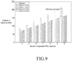
- FIG. 9 illustrates an enhancement achieved by a method for establishing a plurality of PDU sessions based on an iMess as compared with a legacy method for establishing a plurality of PDU sessions.
- FIG. 9 illustrates the number of signaling flows as per variations in the type of PDU sessions requested and the number of PDU sessions requested.
- the number of signaling flows in a standard PDU session establishment process following the call flow of FIGS. 5A and 5B was compared with the number of signaling flows produced in a multiple PDU session establishing process based on the iMess as per the call flow of FIGS. 7A and 7B . Further, performance was measured while varying the number of PDU sessions corresponding to CriC services from zero to three assuming the circumstance where three CriC service applications, such as V2X, remote-control, and AR/VR, are running.
- PDU session establishment utilizing the iMess shows a performance enhancement by 26% as compared with standard PDU session establishment.
- serving CN control plane function as shown in FIGS. 10 to 18 may include an AMF, embodiments of the disclosure are not limited thereto.
- FIG. 10 illustrates a flowchart of a migration procedure of an NF based on a database.
- signaling interaction may occur among the UE 40 , the RAN 41 , and the database 42 , so that the UE 40 may send a service request message to the new serving CN control plane function 44 .
- the UE 40 attempts to send a service request to the RAN 41 to exchange initial signaling with the core network (CN).
- CN core network
- the RAN 41 inquires the database 42 to obtain information about which serving CN control plane function 43 the UE 40 needs to connect to.
- the RAN 41 interprets serving CN control plane function ( 43 ) information received from the database 42 , obtaining the physical address (e.g., IP address).
- the physical address e.g., IP address
- the RAN 41 performs a TNL association process between the RAN 41 and the serving CN control plane function 43 through the physical address. Where there is a connection already made between the RAN 41 and the serving CN control plane function 43 by another UE 40 , the operation may be omitted.
- the RAN 41 makes a UE-specific connection between the RAN 41 and the serving CN control plane function 43 .
- the RAN 41 delivers a signaling message via the UE-specific connection made in operation 609 without inquiring the database 42 .
- the signaling message is a NAS message.
- the database 42 stores new serving CN control plane function ( 44 ) information.
- the prior serving CN control plane function 43 sends a NG 2 message to the RAN 41 , terminating the UE-specific RAN-CN connection.
- the UE 40 attempts to send a service request to the RAN 41 to exchange initial signaling with a new core network (CN). For example, the UE 40 may transfer a new NAS message to the RAN 41 .
- CN core network
- the RAN 41 inquires the database 42 to obtain information about which new serving CN control plane function 44 the UE 40 needs to connect to.
- the RAN 41 interprets new serving CN control plane function ( 44 ) information received from the database 42 , obtaining the physical address (e.g., IP address).
- the physical address e.g., IP address
- the RAN 41 performs a TNL association process between the RAN 41 and the new serving CN control plane function 44 through the physical address.
- the RAN 41 makes a UE-specific connection between the RAN 41 and the new serving CN control plane function 44 .
- the RAN 41 proceeds to exchange UE-initiated NAS messages that have not been processed through the UE-specific connection made in operation 627 .
- legacy 4G networks e.g., LTE networks
- GUI globally unique temporary identifier
- users connect to a particular mobility management entity (MME) that manages them via the GUTI, and the radio access network (RAN) transfers the users' control messages (e.g., NAS messages) to the particular MME based on the GUTI.
- MME mobility management entity
- RAN radio access network
- connecting particular entities via identifiers is called stickiness.
- the functions in the MME are defined as virtualized functions, and generation, deletion, and migration of functions frequently occur.
- supporting connectivity between the UE and the network control plane via an identifier denoting a particular network function (NF) as previous requires that the user be frequently notified of the identifier, causing large overhead on the UE side.
- NF network function
- FIGS. 1 to 9 illustrate examples in which one UE and one AMF perform signaling, if a migration occurs from a first AMF of a plurality of AMFs included in the AMF pool of FIG. 6 to a second AMF, the UE 40 needs to re-send a NAS message to the second AMF.
- the conventional Intel solution is a reactive type in which UE-AMF connectivity is supported in such a way that the UE is disconnected from the AMF when the AMF changes to another and is later reconnected as necessary. For such reason, latency occurs in exchanging NAS messages between the UE 40 and the new AMF.
- the 5G system may further include a proxy-based NF connected to each of an (R)AN and an NF, addressing the conventional stickiness issue based on the proxy network function (NF) while shortening the latency consumed in delivering a new NAS message after changing the NF.
- a proxy-based NF connected to each of an (R)AN and an NF, addressing the conventional stickiness issue based on the proxy network function (NF) while shortening the latency consumed in delivering a new NAS message after changing the NF.
- FIGS. 11 and 12 illustrate various examples of implementing a proxy-based NF.
- a proxy 52 a may be implemented as one NF in the data center.
- a proxy 52 b may be implemented along with an eNB 51 b .
- proxies described herein may be implemented with entities as shown in FIGS. 11 and 12 .
- FIG. 13 illustrates compatibility between a temporary ID (temp ID) architecture and an embodiment of the present disclosure.
- the AMF group ID 1350 a of the legacy temp ID architecture 1300 defined by the 3GPP may match the proxy ID 1350 b according to the disclosure. This represents that embodiments of the disclosure can be implemented without modifying the 3GPP temp ID architecture 1300 .
- FIG. 14 illustrates flowchart of a procedure for a proxy NF-based NF migration supporting scheme
- the UE 50 a attempts to send a service request to the RAN 51 a to exchange initial signaling with the core network (CN). For example, the UE 50 a may transmit a service request message to the RAN 51 a.
- CN core network
- the RAN 51 a transfers the service request received in operation 701 to the proxy 52 a.
- the proxy 52 a performs TNL connection with the RAN 51 a.
- the proxy 52 a performs TNL connection with the serving CN control plane function 53 a as well.
- the RAN 51 a and the proxy 52 a perform UE-specific sticky connection.
- the serving CN control plane function 53 a and the proxy 52 a also perform UE-specific sticky connection.
- NAS messages are exchanged between the UE 50 a and the serving CN control plane function 53 a via the UE-specific sticky connection.
- the serving CN control plane function 53 a releases the UE-specific sticky connection with the proxy 52 a and provides information about the new serving CN control plane function 54 a to the proxy 52 a.
- the serving CN control plane function 53 a transfers a connection maintenance flag message to the proxy 52 a to indicate that the connection needs to last.
- the proxy 52 a performs TNL connection with the new serving CN control plane function 54 a.
- a UE-specific sticky connection is established between the proxy 52 a and the new serving CN control plane function 54 a.
- the NAS message of the UE 50 a is exchanged with the new serving CN control plane function 54 a via the UE-specific sticky connection.
- connection between the proxy 52 a and the new NF 54 a may proactively be performed (operations 715 to 723 ).
- latency may be further reduced in transferring new NAS messages.
- costs may be incurred to maintain the RAN-proxy-AMF connection (i.e., N2AP connection) even after the NF's migration. That is, there is a trade-off between NAS message transfer latency and costs for maintaining connection.
- the constancy of the RAN-proxy-AMF connection may be determined per network slice (NS).
- FIG. 15 illustrates various examples of managing the constancy of the RAN-proxy-AMF connection (i.e, N2AP connection) based on the characteristics of the network slice (NS).
- N2AP connection i.e, N2AP connection
- UE 1 60 a and UE 2 60 b are connected to a data center for slice 1 (NS 1 ) and a data center for slice 2 (NS 2 ), respectively, and the data center for slice 1 (NS 1 ) is a slice that offers latency-sensitive services, but the data center for slice 2 (NS 2 ) is not, the N2AP connection of the data center for slice 1 (NS 1 ) may always be maintained, but the N2AP connection of the data center for slice 2 (NS 2 ) might not.
- FIGS. 16A and 16B illustrates operations on a slice that does not maintain N2AP connection.
- the serving CN control plane function 63 a (i.e., the AMF) of the NS determines whether the N2AP connection lasts and notifies the proxy 62 a of the same.
- operation 819 may be omitted.
- a process (operations 825 to 837 ) is required to establish a new N2AP connection.
- a bottleneck may occur in which all NAS messages may be processed by the proxy 62 a .
- Simple schemes for selecting the proxy 62 a may include database-based load balancing supporting and random selection-based load balancing supporting.
- FIG. 17 illustrates a flowchart of a procedure for database-based load balancing supporting.
- operation 901 corresponds to operation 701 of FIG. 14 , no detailed description thereof is given.
- the RAN 71 obtains information about a proxy available from the proxy pool by an inquiry/response process. For example, the RAN 71 may inquire the database to obtain information about a low-load proxy 73 a and make a connection to the proxy 73 a.
- the RAN 71 upon initial access, inquires the database about a proxy 73 a (e.g., a low-load proxy) available from the proxy pool, and the database transmits information about the available proxy 73 a to the RAN 71 .
- a proxy 73 a e.g., a low-load proxy
- FIG. 18 illustrates a flowchart of a procedure for random selection-based load balancing supporting.
- operation 1001 corresponds to operation 701 of FIG. 14 , no detailed description thereof is given.
- the RAN 71 selects any proxy from the proxy pool. For example, upon initial access, the RAN 71 may select any proxy 73 b from the proxy pool and may make a connection to the proxy 73 b.
- Random selection-based load balancing supporting may not deliver precise load distribution effects as compared with the database-based load balancing supporting but may be advantageous in that the proxies do not have load maintenance overhead.
- FIG. 19 illustrates a graph of a latency ratio of the conventional solution and an embodiment of the disclosure that has been measured while prolonging the mean occurrence period of the NAS message.
- an event-driven simulator was developed to a latency reduction rate relative to the existing solution (the Intel solution). As evident from FIG. 19 , the embodiment of the disclosure could save latency by 3% to 70%.
- FIG. 20 illustrates an example of a configuration of a UE in which a method for establishing a plurality of PDU sessions is implemented according to an embodiment.
- a method for establishing a plurality of PDU sessions may be implemented on a UE 1000 or recorded in a recording medium.
- the UE 1000 may include at least one or more processors 1100 and a memory 1200 .
- the processor 1100 may be a central processing unit (CPU) or a semiconductor device to process instructions stored in the memory 1200 .
- CPU central processing unit
- semiconductor device to process instructions stored in the memory 1200 .
- the processor 1100 may be a controller to control all the operations of the UE 1000 .
- the controller may execute the operations of the UE 1000 by reading the programming code out of the memory 120 and running the programming code.
- the UE 1000 may further include at least one of a user input circuit 1500 , a data communication bus 1300 , or a user output circuit 1600 .
- the above-described components may perform data communication through the data communication bus 1300 .
- the UE 1000 may further include a network interface 1700 connected to the network output circuit 1800 .
- the memory 1200 may include various types of volatile or non-volatile storage media.
- the memory 1200 may include a read only memory (ROM) 1230 and a random access memory (RAM) 1260 .
- ROM read only memory
- RAM random access memory
- a method for establishing a plurality of PDU session may be implemented in such a manner as to be able to run on a computer.
- computer readable commands may perform the operation method according to the disclosure.
- a method for establishing a plurality of PDU sessions may be implemented in codes that a computer may read out of a recording medium, according to an embodiment.
- the computer-readable recording medium includes all types of recording media storing data that can be read out or interpreted by the UE 1000 .
- the computer-readable recording medium may include a ROM, a RAM, a magnetic tape, a magnetic disc, a flash memory, and an optical data storage device.
- the computer-readable recording medium may be distributed on the UE 1000 connected via the computer communication network and may be stored and run as codes readable in a distributive manner.
- CN core network
- NFs network functions
- R R
- DN data network
- FIGS. 21 and 22 illustrate flowcharts of a method for establishing a plurality of PDU sessions according to an embodiment.
- the UE transmits a message to establish a plurality of PDU sessions to at least one NF among a plurality of NFs.
- the message may contain information about a service corresponding to the plurality of PDU sessions.
- the message may be a NAS message containing an iMess as shown in FIG. 6 .
- the iMess may include an AMF ID field containing information about a core access and mobility management function (AMF) to which the UE desires to send a PDU session establishment request, a flag field containing information about the number of the plurality of PDU sessions which the UE desires to establish and the number of PDU sessions providing a CriC service among the plurality of PDU sessions, and a plurality of PSI fields containing information about a plurality of PDU session requests.
- AMF core access and mobility management function
- the plurality of PSI fields may be sorted top to down corresponding to the priority of establishing the plurality of PDU sessions.
- the message may include multiple PDU session establishment request information and may be a NAS message that is sent out while the first one of the plurality of PDU sessions is established.
- signals are exchanged to establish a plurality of PDU sessions among the UE, the (R)AN, and the plurality of network functions based on the message received in operation 1100 .
- the AMF may previously and collectively fetch subscription data related to the UE from the UDM and may transmit an SM request containing the UE's subscription data and the UE's PDU session establishment request to the SMF.
- the number of times of duplicate signaling may be reduced by previously and collectively fetching the UE-related subscription data from the UDM, minimizing interactions between the UE and the CN.
- the SMF upon receiving the UE's request for establishing multiple PDU sessions and the SM request containing the UE's subscription data from the AMF, may exchange signaling with other NFs (the PCF, UPF, and AMF) and other network components (the DN, (R)AN, and UE), proceeding to establish the sessions.
- the PCF the PCF, UPF, and AMF
- the DN, (R)AN the DN, (R)AN, and UE
- a plurality of PDU sessions are established according to predetermined priority between the UE and the data network (DN) based on the signals exchanged in operation 1120 .
- the plurality of PDU sessions may sequentially be established based on the order of sorting the PSI fields contained in the iMess.
- the order of sorting the PSI fields may be determined by the priority determined based on the information about the services corresponding to the PDU sessions. For example, the PSI corresponding to the CriC service requiring immediate PDU session establishment is positioned higher than the PSIs corresponding to the eMBB or mIoT, so that the PDU session corresponding to the CriC service is given a higher priority than the PDU sessions corresponding to the eMBB or mIoT service.
- the priority related to establishing the plurality of PDU sessions may directly be set by the user. Further, the priority may be determined based on requirements for the utilization, latency, and reliability of each of the plurality of CriC service-required applications and the UE's environment.
- the AMF may produce a single N2 PDU session request by integrating the information about the plurality of PDU session corresponding to the eMBB or mIoT, not the CriC service, and transfer the N2 PDU session request to the (R)AN. That is, the interactions between the UE and the CN may be minimized by integrating the N2 PDU session request ack and the N2 PDU session request related to establishing a plurality of PDU sessions into a single message and exchanging the same between the (R)AN and the AMF.
- a method for establishing a plurality of PDU sessions may adopt a new indicator called an indicator for multiple PDU session establishment (iMess), shortening the process for a UE to request and establish multiple PDU sessions via an adaptive interaction between the network functions based on the iMess.
- iMess an indicator for multiple PDU session establishment
- a method for establishing a plurality of PDU sessions may further include a proxy-based NF connected to each of an (R)AN and an NF, addressing the conventional stickiness issue while shortening the latency consumed in delivering a new NAS message after changing the NF.
- a method for establishing a plurality of PDU sessions adopts a proxy-based NF in supporting connectivity between a UE and an AMF, reducing the latency consumed in transferring a new NAS message after the AMF is changed.
Landscapes
- Engineering & Computer Science (AREA)
- Computer Networks & Wireless Communication (AREA)
- Signal Processing (AREA)
- Computer Security & Cryptography (AREA)
- Mobile Radio Communication Systems (AREA)
Abstract
Description
Claims (13)
Applications Claiming Priority (2)
| Application Number | Priority Date | Filing Date | Title |
|---|---|---|---|
| KR1020170072750A KR102224248B1 (en) | 2017-06-09 | 2017-06-09 | Method for establishing protocol data unit in communication system |
| KR10-2017-0072750 | 2017-06-09 |
Publications (2)
| Publication Number | Publication Date |
|---|---|
| US20180359795A1 US20180359795A1 (en) | 2018-12-13 |
| US10798761B2 true US10798761B2 (en) | 2020-10-06 |
Family
ID=64563870
Family Applications (1)
| Application Number | Title | Priority Date | Filing Date |
|---|---|---|---|
| US16/003,530 Active 2038-11-10 US10798761B2 (en) | 2017-06-09 | 2018-06-08 | Method for establishing protocol data unit session in communication system |
Country Status (2)
| Country | Link |
|---|---|
| US (1) | US10798761B2 (en) |
| KR (1) | KR102224248B1 (en) |
Cited By (4)
| Publication number | Priority date | Publication date | Assignee | Title |
|---|---|---|---|---|
| US11172521B2 (en) * | 2017-08-11 | 2021-11-09 | Huawei Technologies Co., Ltd. | System and method for management of session information in data communication network |
| US11184417B2 (en) * | 2019-10-08 | 2021-11-23 | Qualcomm Incorporated | System and apparatus for providing network assistance for traffic handling in downlink streaming |
| US11350315B2 (en) * | 2017-11-09 | 2022-05-31 | Huawei Technologies Co., Ltd. | Communication method and network device |
| US11375470B2 (en) * | 2017-02-02 | 2022-06-28 | Qualcomm Incorporated | Network assisted multi-subscription physical layer sharing |
Families Citing this family (30)
| Publication number | Priority date | Publication date | Assignee | Title |
|---|---|---|---|---|
| US9628828B2 (en) * | 2014-12-15 | 2017-04-18 | Cable Television Laboratories, Inc. | Software defined networking in a cable TV system |
| US10397892B2 (en) * | 2017-02-06 | 2019-08-27 | Huawei Technologies Co., Ltd. | Network registration and network slice selection system and method |
| US11284250B2 (en) * | 2017-06-16 | 2022-03-22 | Telefonaktiebolaget Lm Ericsson (Publ) | Network, network nodes, wireless communication devices and method therein for handling network slices in a wireless communication network |
| CN117793952A (en) * | 2017-08-11 | 2024-03-29 | 华为技术有限公司 | Communication method and device |
| US10797894B2 (en) * | 2017-12-28 | 2020-10-06 | Ofinno, Llc | Service type and device type-based policy and charging control |
| US10484911B1 (en) | 2018-05-23 | 2019-11-19 | Verizon Patent And Licensing Inc. | Adaptable radio access network |
| US10581984B2 (en) * | 2018-07-23 | 2020-03-03 | Cisco Technology, Inc. | Methods and apparatus for providing information associated with network function (NF) instances of a 5G mobile network |
| CN110933623B (en) * | 2018-09-17 | 2021-08-31 | 华为技术有限公司 | Communication method and device |
| US10848576B2 (en) * | 2018-10-29 | 2020-11-24 | Cisco Technology, Inc. | Network function (NF) repository function (NRF) having an interface with a segment routing path computation entity (SR-PCE) for improved discovery and selection of NF instances |
| US10999447B2 (en) * | 2018-11-02 | 2021-05-04 | Ofinno, Llc | Charging control in roaming scenario |
| CN111225013A (en) * | 2018-11-27 | 2020-06-02 | 华为技术有限公司 | Transmission strategy determination method, strategy control method and device |
| CN111479298B (en) * | 2019-01-23 | 2023-10-20 | 华为技术有限公司 | Method and device for controlling power consumption |
| US11425583B2 (en) | 2019-04-02 | 2022-08-23 | Electronics And Telecommunications Research Institute | Network data collection method from application function device for network data analytic function |
| WO2020256425A1 (en) * | 2019-06-18 | 2020-12-24 | Lg Electronics Inc. | Method and apparatus for supporting redundant pdu sessions |
| US11265771B2 (en) * | 2019-08-14 | 2022-03-01 | Mediatek Inc. | AT commands for supporting session and service continuity modes of 5G protocol data unitsession operations |
| KR20210021837A (en) * | 2019-08-19 | 2021-03-02 | 삼성전자주식회사 | Method and apparatus for providing multiple subscriptions in a wireless communication system |
| KR102207786B1 (en) * | 2019-10-02 | 2021-01-26 | 에스케이텔레콤 주식회사 | User plane function and method for identifying application using the same |
| KR102209719B1 (en) * | 2019-10-07 | 2021-02-01 | 에스케이텔레콤 주식회사 | Apparatus for controlling User Plane in communication system and Method therefor |
| CN112702801B (en) * | 2019-10-22 | 2022-12-16 | 大唐移动通信设备有限公司 | Method and device for establishing session |
| US10986568B1 (en) * | 2019-10-31 | 2021-04-20 | Verizon Patent And Licensing Inc. | Systems and methods for providing network slice selection assistance and route selection policy configurations in a universal integrated circuit card |
| CN112822678B (en) * | 2019-10-31 | 2022-05-06 | 华为技术有限公司 | Method for authorizing service architecture |
| CN111107666B (en) * | 2019-12-30 | 2022-02-18 | 联想(北京)有限公司 | PDU session-based network element selection method, device and storage medium |
| US11166326B2 (en) * | 2020-01-21 | 2021-11-02 | Juniper Networks, Inc. | Utilizing a transport protocol for fifth generation (5G) client devices to carry messages on wireline access |
| CN111405682B (en) * | 2020-03-19 | 2024-04-16 | 中国联合网络通信集团有限公司 | Data forwarding method and gateway |
| CN112188643B (en) * | 2020-10-09 | 2022-11-15 | 哲库科技(北京)有限公司 | PDU session establishment method, device, terminal and storage medium |
| US11736761B2 (en) * | 2021-03-16 | 2023-08-22 | Tencent America LLC | Methods for media streaming content preparation for an application provider in 5G networks |
| KR102525736B1 (en) * | 2021-06-17 | 2023-04-25 | 에스케이텔레콤 주식회사 | Network function device and proccessing method for service requests |
| WO2023043926A1 (en) * | 2021-09-16 | 2023-03-23 | Dish Wireless L.L.C. | Method and system for network function migration procedures for a signaling control plane |
| US11888677B2 (en) | 2021-09-16 | 2024-01-30 | Dish Wireless L.L.C. | Method and system for network function migration procedures for a signaling control plane |
| CN114666919B (en) * | 2022-05-18 | 2022-08-30 | 广州世炬网络科技有限公司 | Random access method, information broadcasting device and electronic equipment |
Citations (7)
| Publication number | Priority date | Publication date | Assignee | Title |
|---|---|---|---|---|
| US20170303259A1 (en) * | 2016-04-18 | 2017-10-19 | Electronics And Telecommunications Research Institute | Communication method and apparatus using network slicing |
| US20170359749A1 (en) * | 2016-06-10 | 2017-12-14 | Huawei Technologies Co., Ltd. | Systems and method for quality of service monitoring, policy enforcement, and charging in a communications network |
| US20180199115A1 (en) * | 2017-01-09 | 2018-07-12 | Athul Prasad | Broadcasting, multicasting, or unicasting advertising content based on user context |
| US20180262924A1 (en) * | 2017-03-10 | 2018-09-13 | Huawei Technologies Co., Ltd. | System and Method of Network Policy Optimization |
| US20190021010A1 (en) * | 2017-07-05 | 2019-01-17 | Huawei Technologies Co., Ltd. | Methods and systems for network slicing |
| US20190191348A1 (en) * | 2016-08-10 | 2019-06-20 | Nec Corporation | Radio access network node, radio terminal, core network node, and method therefor |
| US20190238413A1 (en) * | 2016-09-29 | 2019-08-01 | Telefonaktiebolaget Lm Ericsson (Publ) | Quality Of Service Differentiation Between Network Slices |
Family Cites Families (4)
| Publication number | Priority date | Publication date | Assignee | Title |
|---|---|---|---|---|
| US8532614B2 (en) * | 2007-10-25 | 2013-09-10 | Interdigital Patent Holdings, Inc. | Non-access stratum architecture and protocol enhancements for long term evolution mobile units |
| KR102506270B1 (en) * | 2015-09-07 | 2023-03-07 | 한국전자통신연구원 | Mobile communication network system and method for composing network component configurations |
| US10425830B2 (en) * | 2015-09-07 | 2019-09-24 | Electronics And Telecommunications Research Institute | Mobile communication network system and method for composing network component configurations |
| US9775045B2 (en) * | 2015-09-11 | 2017-09-26 | Intel IP Corporation | Slicing architecture for wireless communication |
-
2017
- 2017-06-09 KR KR1020170072750A patent/KR102224248B1/en active IP Right Grant
-
2018
- 2018-06-08 US US16/003,530 patent/US10798761B2/en active Active
Patent Citations (7)
| Publication number | Priority date | Publication date | Assignee | Title |
|---|---|---|---|---|
| US20170303259A1 (en) * | 2016-04-18 | 2017-10-19 | Electronics And Telecommunications Research Institute | Communication method and apparatus using network slicing |
| US20170359749A1 (en) * | 2016-06-10 | 2017-12-14 | Huawei Technologies Co., Ltd. | Systems and method for quality of service monitoring, policy enforcement, and charging in a communications network |
| US20190191348A1 (en) * | 2016-08-10 | 2019-06-20 | Nec Corporation | Radio access network node, radio terminal, core network node, and method therefor |
| US20190238413A1 (en) * | 2016-09-29 | 2019-08-01 | Telefonaktiebolaget Lm Ericsson (Publ) | Quality Of Service Differentiation Between Network Slices |
| US20180199115A1 (en) * | 2017-01-09 | 2018-07-12 | Athul Prasad | Broadcasting, multicasting, or unicasting advertising content based on user context |
| US20180262924A1 (en) * | 2017-03-10 | 2018-09-13 | Huawei Technologies Co., Ltd. | System and Method of Network Policy Optimization |
| US20190021010A1 (en) * | 2017-07-05 | 2019-01-17 | Huawei Technologies Co., Ltd. | Methods and systems for network slicing |
Non-Patent Citations (8)
Cited By (5)
| Publication number | Priority date | Publication date | Assignee | Title |
|---|---|---|---|---|
| US11375470B2 (en) * | 2017-02-02 | 2022-06-28 | Qualcomm Incorporated | Network assisted multi-subscription physical layer sharing |
| US11172521B2 (en) * | 2017-08-11 | 2021-11-09 | Huawei Technologies Co., Ltd. | System and method for management of session information in data communication network |
| USRE49729E1 (en) * | 2017-08-11 | 2023-11-14 | Huawei Technologies Co., Ltd. | Session information management method and apparatus |
| US11350315B2 (en) * | 2017-11-09 | 2022-05-31 | Huawei Technologies Co., Ltd. | Communication method and network device |
| US11184417B2 (en) * | 2019-10-08 | 2021-11-23 | Qualcomm Incorporated | System and apparatus for providing network assistance for traffic handling in downlink streaming |
Also Published As
| Publication number | Publication date |
|---|---|
| KR20180134685A (en) | 2018-12-19 |
| KR102224248B1 (en) | 2021-03-08 |
| US20180359795A1 (en) | 2018-12-13 |
Similar Documents
| Publication | Publication Date | Title |
|---|---|---|
| US10798761B2 (en) | Method for establishing protocol data unit session in communication system | |
| US11122415B2 (en) | Method and device using network slicing in mobile communication system | |
| KR102387239B1 (en) | Mobile Network Interaction Proxy | |
| KR102633995B1 (en) | Method and apparatus for requesting authorization between terminal and third party in wireless communication system | |
| WO2018171375A1 (en) | Method for network slice selection, user equipment, and network device | |
| US10841964B2 (en) | Systems and methods for RAN slicing in a wireless access network | |
| US11172405B2 (en) | Method for checking change in wireless connection type of terminal in third-party application server | |
| EP3165032B1 (en) | Apparatus and method for providing a service connection through access layer in wireless communication system | |
| US11683723B2 (en) | Methods and system for offloading data traffic | |
| US20220322067A1 (en) | Method and apparatus for configuring temporary user equipment (ue) external identifier in wireless communication system | |
| CN112806056A (en) | Method and apparatus for supporting mobile edge computing transitions in a wireless communication system | |
| WO2022073213A1 (en) | Mechanism for dynamic authorization | |
| CN114731723A (en) | Communication method and device | |
| US20230308429A1 (en) | Method and apparatus related to authorisation tokens for service requests | |
| US20230124206A1 (en) | Apparatus, methods, and computer programs | |
| CN114071649B (en) | Method and device for accessing local network | |
| US20230137283A1 (en) | Systems and methods to optimize registration and session establishment in a wireless network | |
| CN117280676A (en) | User plane function selection support method and apparatus in wireless communication system | |
| CN116868603A (en) | New method for external parameter provisioning for AF sessions | |
| US20230116405A1 (en) | Method and device for session breakout of home routed session in visited plmn in wireless communication system | |
| US20240155418A1 (en) | Method and apparatus for connecting qos flow based terminal in wireless communication system | |
| US20230109814A1 (en) | Method and apparatus for managing registration of network slice in wireless communication system | |
| WO2023143212A1 (en) | Communication method and apparatus | |
| EP4106273A1 (en) | Apparatus, methods, and computer programs | |
| WO2021244622A1 (en) | Communication method and apparatus, and computer-readable storage medium |
Legal Events
| Date | Code | Title | Description |
|---|---|---|---|
| AS | Assignment |
Owner name: KOREA UNIVERSITY RESEARCH AND BUSINESS FOUNDATION, Free format text: ASSIGNMENT OF ASSIGNORS INTEREST;ASSIGNORS:BAEK, YOUNG-KYO;SON, JUNG-JE;KIM, SUNG-HOON;AND OTHERS;REEL/FRAME:046028/0751 Effective date: 20180604 Owner name: SAMSUNG ELECTRONICS CO., LTD., KOREA, REPUBLIC OF Free format text: ASSIGNMENT OF ASSIGNORS INTEREST;ASSIGNORS:BAEK, YOUNG-KYO;SON, JUNG-JE;KIM, SUNG-HOON;AND OTHERS;REEL/FRAME:046028/0751 Effective date: 20180604 Owner name: KOREA UNIVERSITY RESEARCH AND BUSINESS FOUNDATION, KOREA, REPUBLIC OF Free format text: ASSIGNMENT OF ASSIGNORS INTEREST;ASSIGNORS:BAEK, YOUNG-KYO;SON, JUNG-JE;KIM, SUNG-HOON;AND OTHERS;REEL/FRAME:046028/0751 Effective date: 20180604 |
|
| FEPP | Fee payment procedure |
Free format text: ENTITY STATUS SET TO UNDISCOUNTED (ORIGINAL EVENT CODE: BIG.); ENTITY STATUS OF PATENT OWNER: LARGE ENTITY |
|
| STPP | Information on status: patent application and granting procedure in general |
Free format text: DOCKETED NEW CASE - READY FOR EXAMINATION |
|
| STPP | Information on status: patent application and granting procedure in general |
Free format text: NON FINAL ACTION MAILED |
|
| STPP | Information on status: patent application and granting procedure in general |
Free format text: RESPONSE TO NON-FINAL OFFICE ACTION ENTERED AND FORWARDED TO EXAMINER |
|
| STPP | Information on status: patent application and granting procedure in general |
Free format text: FINAL REJECTION MAILED |
|
| STPP | Information on status: patent application and granting procedure in general |
Free format text: RESPONSE AFTER FINAL ACTION FORWARDED TO EXAMINER |
|
| STPP | Information on status: patent application and granting procedure in general |
Free format text: PUBLICATIONS -- ISSUE FEE PAYMENT VERIFIED |
|
| STCF | Information on status: patent grant |
Free format text: PATENTED CASE |