US10789876B2 - Display system and method of driving the same - Google Patents
Display system and method of driving the same Download PDFInfo
- Publication number
- US10789876B2 US10789876B2 US15/702,868 US201715702868A US10789876B2 US 10789876 B2 US10789876 B2 US 10789876B2 US 201715702868 A US201715702868 A US 201715702868A US 10789876 B2 US10789876 B2 US 10789876B2
- Authority
- US
- United States
- Prior art keywords
- data
- pivot
- image data
- touch
- graphic processing
- Prior art date
- Legal status (The legal status is an assumption and is not a legal conclusion. Google has not performed a legal analysis and makes no representation as to the accuracy of the status listed.)
- Active, expires
Links
- 238000000034 method Methods 0.000 title claims description 121
- 230000004044 response Effects 0.000 claims abstract description 59
- 230000006870 function Effects 0.000 claims description 156
- 230000008569 process Effects 0.000 claims description 99
- 230000003247 decreasing effect Effects 0.000 abstract description 32
- 238000004519 manufacturing process Methods 0.000 abstract description 12
- IYZMXHQDXZKNCY-UHFFFAOYSA-N 1-n,1-n-diphenyl-4-n,4-n-bis[4-(n-phenylanilino)phenyl]benzene-1,4-diamine Chemical compound C1=CC=CC=C1N(C=1C=CC(=CC=1)N(C=1C=CC(=CC=1)N(C=1C=CC=CC=1)C=1C=CC=CC=1)C=1C=CC(=CC=1)N(C=1C=CC=CC=1)C=1C=CC=CC=1)C1=CC=CC=C1 IYZMXHQDXZKNCY-UHFFFAOYSA-N 0.000 description 51
- 239000008186 active pharmaceutical agent Substances 0.000 description 45
- 102100040862 Dual specificity protein kinase CLK1 Human genes 0.000 description 44
- 102100040844 Dual specificity protein kinase CLK2 Human genes 0.000 description 30
- 101000749294 Homo sapiens Dual specificity protein kinase CLK1 Proteins 0.000 description 30
- 101000749291 Homo sapiens Dual specificity protein kinase CLK2 Proteins 0.000 description 30
- 230000001360 synchronised effect Effects 0.000 description 28
- 238000010586 diagram Methods 0.000 description 16
- 230000003252 repetitive effect Effects 0.000 description 7
- 238000012986 modification Methods 0.000 description 3
- 230000004048 modification Effects 0.000 description 3
- 239000004973 liquid crystal related substance Substances 0.000 description 2
- 238000010897 surface acoustic wave method Methods 0.000 description 2
- PBGKNXWGYQPUJK-UHFFFAOYSA-N 4-chloro-2-nitroaniline Chemical compound NC1=CC=C(Cl)C=C1[N+]([O-])=O PBGKNXWGYQPUJK-UHFFFAOYSA-N 0.000 description 1
- 230000001413 cellular effect Effects 0.000 description 1
- 230000008859 change Effects 0.000 description 1
- 238000010276 construction Methods 0.000 description 1
Images


Classifications
-
- G—PHYSICS
- G06—COMPUTING; CALCULATING OR COUNTING
- G06F—ELECTRIC DIGITAL DATA PROCESSING
- G06F3/00—Input arrangements for transferring data to be processed into a form capable of being handled by the computer; Output arrangements for transferring data from processing unit to output unit, e.g. interface arrangements
- G06F3/01—Input arrangements or combined input and output arrangements for interaction between user and computer
- G06F3/03—Arrangements for converting the position or the displacement of a member into a coded form
- G06F3/041—Digitisers, e.g. for touch screens or touch pads, characterised by the transducing means
- G06F3/0416—Control or interface arrangements specially adapted for digitisers
- G06F3/04166—Details of scanning methods, e.g. sampling time, grouping of sub areas or time sharing with display driving
-
- G—PHYSICS
- G09—EDUCATION; CRYPTOGRAPHY; DISPLAY; ADVERTISING; SEALS
- G09G—ARRANGEMENTS OR CIRCUITS FOR CONTROL OF INDICATING DEVICES USING STATIC MEANS TO PRESENT VARIABLE INFORMATION
- G09G3/00—Control arrangements or circuits, of interest only in connection with visual indicators other than cathode-ray tubes
- G09G3/20—Control arrangements or circuits, of interest only in connection with visual indicators other than cathode-ray tubes for presentation of an assembly of a number of characters, e.g. a page, by composing the assembly by combination of individual elements arranged in a matrix no fixed position being assigned to or needed to be assigned to the individual characters or partial characters
- G09G3/34—Control arrangements or circuits, of interest only in connection with visual indicators other than cathode-ray tubes for presentation of an assembly of a number of characters, e.g. a page, by composing the assembly by combination of individual elements arranged in a matrix no fixed position being assigned to or needed to be assigned to the individual characters or partial characters by control of light from an independent source
- G09G3/36—Control arrangements or circuits, of interest only in connection with visual indicators other than cathode-ray tubes for presentation of an assembly of a number of characters, e.g. a page, by composing the assembly by combination of individual elements arranged in a matrix no fixed position being assigned to or needed to be assigned to the individual characters or partial characters by control of light from an independent source using liquid crystals
- G09G3/3611—Control of matrices with row and column drivers
-
- G—PHYSICS
- G06—COMPUTING; CALCULATING OR COUNTING
- G06F—ELECTRIC DIGITAL DATA PROCESSING
- G06F3/00—Input arrangements for transferring data to be processed into a form capable of being handled by the computer; Output arrangements for transferring data from processing unit to output unit, e.g. interface arrangements
- G06F3/01—Input arrangements or combined input and output arrangements for interaction between user and computer
- G06F3/03—Arrangements for converting the position or the displacement of a member into a coded form
- G06F3/041—Digitisers, e.g. for touch screens or touch pads, characterised by the transducing means
- G06F3/0412—Digitisers structurally integrated in a display
-
- G—PHYSICS
- G06—COMPUTING; CALCULATING OR COUNTING
- G06F—ELECTRIC DIGITAL DATA PROCESSING
- G06F3/00—Input arrangements for transferring data to be processed into a form capable of being handled by the computer; Output arrangements for transferring data from processing unit to output unit, e.g. interface arrangements
- G06F3/01—Input arrangements or combined input and output arrangements for interaction between user and computer
- G06F3/03—Arrangements for converting the position or the displacement of a member into a coded form
- G06F3/041—Digitisers, e.g. for touch screens or touch pads, characterised by the transducing means
- G06F3/0416—Control or interface arrangements specially adapted for digitisers
-
- G—PHYSICS
- G06—COMPUTING; CALCULATING OR COUNTING
- G06F—ELECTRIC DIGITAL DATA PROCESSING
- G06F3/00—Input arrangements for transferring data to be processed into a form capable of being handled by the computer; Output arrangements for transferring data from processing unit to output unit, e.g. interface arrangements
- G06F3/01—Input arrangements or combined input and output arrangements for interaction between user and computer
- G06F3/03—Arrangements for converting the position or the displacement of a member into a coded form
- G06F3/041—Digitisers, e.g. for touch screens or touch pads, characterised by the transducing means
- G06F3/044—Digitisers, e.g. for touch screens or touch pads, characterised by the transducing means by capacitive means
-
- G—PHYSICS
- G06—COMPUTING; CALCULATING OR COUNTING
- G06T—IMAGE DATA PROCESSING OR GENERATION, IN GENERAL
- G06T3/00—Geometric image transformations in the plane of the image
- G06T3/60—Rotation of whole images or parts thereof
-
- G—PHYSICS
- G09—EDUCATION; CRYPTOGRAPHY; DISPLAY; ADVERTISING; SEALS
- G09G—ARRANGEMENTS OR CIRCUITS FOR CONTROL OF INDICATING DEVICES USING STATIC MEANS TO PRESENT VARIABLE INFORMATION
- G09G3/00—Control arrangements or circuits, of interest only in connection with visual indicators other than cathode-ray tubes
- G09G3/20—Control arrangements or circuits, of interest only in connection with visual indicators other than cathode-ray tubes for presentation of an assembly of a number of characters, e.g. a page, by composing the assembly by combination of individual elements arranged in a matrix no fixed position being assigned to or needed to be assigned to the individual characters or partial characters
- G09G3/2092—Details of a display terminals using a flat panel, the details relating to the control arrangement of the display terminal and to the interfaces thereto
- G09G3/2096—Details of the interface to the display terminal specific for a flat panel
-
- G—PHYSICS
- G09—EDUCATION; CRYPTOGRAPHY; DISPLAY; ADVERTISING; SEALS
- G09G—ARRANGEMENTS OR CIRCUITS FOR CONTROL OF INDICATING DEVICES USING STATIC MEANS TO PRESENT VARIABLE INFORMATION
- G09G5/00—Control arrangements or circuits for visual indicators common to cathode-ray tube indicators and other visual indicators
- G09G5/36—Control arrangements or circuits for visual indicators common to cathode-ray tube indicators and other visual indicators characterised by the display of a graphic pattern, e.g. using an all-points-addressable [APA] memory
-
- G—PHYSICS
- G09—EDUCATION; CRYPTOGRAPHY; DISPLAY; ADVERTISING; SEALS
- G09G—ARRANGEMENTS OR CIRCUITS FOR CONTROL OF INDICATING DEVICES USING STATIC MEANS TO PRESENT VARIABLE INFORMATION
- G09G2310/00—Command of the display device
- G09G2310/08—Details of timing specific for flat panels, other than clock recovery
-
- G—PHYSICS
- G09—EDUCATION; CRYPTOGRAPHY; DISPLAY; ADVERTISING; SEALS
- G09G—ARRANGEMENTS OR CIRCUITS FOR CONTROL OF INDICATING DEVICES USING STATIC MEANS TO PRESENT VARIABLE INFORMATION
- G09G2320/00—Control of display operating conditions
- G09G2320/02—Improving the quality of display appearance
- G09G2320/0252—Improving the response speed
-
- G—PHYSICS
- G09—EDUCATION; CRYPTOGRAPHY; DISPLAY; ADVERTISING; SEALS
- G09G—ARRANGEMENTS OR CIRCUITS FOR CONTROL OF INDICATING DEVICES USING STATIC MEANS TO PRESENT VARIABLE INFORMATION
- G09G2340/00—Aspects of display data processing
- G09G2340/04—Changes in size, position or resolution of an image
- G09G2340/0492—Change of orientation of the displayed image, e.g. upside-down, mirrored
-
- G—PHYSICS
- G09—EDUCATION; CRYPTOGRAPHY; DISPLAY; ADVERTISING; SEALS
- G09G—ARRANGEMENTS OR CIRCUITS FOR CONTROL OF INDICATING DEVICES USING STATIC MEANS TO PRESENT VARIABLE INFORMATION
- G09G2360/00—Aspects of the architecture of display systems
- G09G2360/08—Power processing, i.e. workload management for processors involved in display operations, such as CPUs or GPUs
-
- G—PHYSICS
- G09—EDUCATION; CRYPTOGRAPHY; DISPLAY; ADVERTISING; SEALS
- G09G—ARRANGEMENTS OR CIRCUITS FOR CONTROL OF INDICATING DEVICES USING STATIC MEANS TO PRESENT VARIABLE INFORMATION
- G09G3/00—Control arrangements or circuits, of interest only in connection with visual indicators other than cathode-ray tubes
- G09G3/20—Control arrangements or circuits, of interest only in connection with visual indicators other than cathode-ray tubes for presentation of an assembly of a number of characters, e.g. a page, by composing the assembly by combination of individual elements arranged in a matrix no fixed position being assigned to or needed to be assigned to the individual characters or partial characters
- G09G3/34—Control arrangements or circuits, of interest only in connection with visual indicators other than cathode-ray tubes for presentation of an assembly of a number of characters, e.g. a page, by composing the assembly by combination of individual elements arranged in a matrix no fixed position being assigned to or needed to be assigned to the individual characters or partial characters by control of light from an independent source
- G09G3/36—Control arrangements or circuits, of interest only in connection with visual indicators other than cathode-ray tubes for presentation of an assembly of a number of characters, e.g. a page, by composing the assembly by combination of individual elements arranged in a matrix no fixed position being assigned to or needed to be assigned to the individual characters or partial characters by control of light from an independent source using liquid crystals
- G09G3/3611—Control of matrices with row and column drivers
- G09G3/3674—Details of drivers for scan electrodes
-
- G—PHYSICS
- G09—EDUCATION; CRYPTOGRAPHY; DISPLAY; ADVERTISING; SEALS
- G09G—ARRANGEMENTS OR CIRCUITS FOR CONTROL OF INDICATING DEVICES USING STATIC MEANS TO PRESENT VARIABLE INFORMATION
- G09G3/00—Control arrangements or circuits, of interest only in connection with visual indicators other than cathode-ray tubes
- G09G3/20—Control arrangements or circuits, of interest only in connection with visual indicators other than cathode-ray tubes for presentation of an assembly of a number of characters, e.g. a page, by composing the assembly by combination of individual elements arranged in a matrix no fixed position being assigned to or needed to be assigned to the individual characters or partial characters
- G09G3/34—Control arrangements or circuits, of interest only in connection with visual indicators other than cathode-ray tubes for presentation of an assembly of a number of characters, e.g. a page, by composing the assembly by combination of individual elements arranged in a matrix no fixed position being assigned to or needed to be assigned to the individual characters or partial characters by control of light from an independent source
- G09G3/36—Control arrangements or circuits, of interest only in connection with visual indicators other than cathode-ray tubes for presentation of an assembly of a number of characters, e.g. a page, by composing the assembly by combination of individual elements arranged in a matrix no fixed position being assigned to or needed to be assigned to the individual characters or partial characters by control of light from an independent source using liquid crystals
- G09G3/3611—Control of matrices with row and column drivers
- G09G3/3685—Details of drivers for data electrodes
-
- G—PHYSICS
- G09—EDUCATION; CRYPTOGRAPHY; DISPLAY; ADVERTISING; SEALS
- G09G—ARRANGEMENTS OR CIRCUITS FOR CONTROL OF INDICATING DEVICES USING STATIC MEANS TO PRESENT VARIABLE INFORMATION
- G09G5/00—Control arrangements or circuits for visual indicators common to cathode-ray tube indicators and other visual indicators
- G09G5/003—Details of a display terminal, the details relating to the control arrangement of the display terminal and to the interfaces thereto
- G09G5/005—Adapting incoming signals to the display format of the display terminal
-
- G—PHYSICS
- G09—EDUCATION; CRYPTOGRAPHY; DISPLAY; ADVERTISING; SEALS
- G09G—ARRANGEMENTS OR CIRCUITS FOR CONTROL OF INDICATING DEVICES USING STATIC MEANS TO PRESENT VARIABLE INFORMATION
- G09G5/00—Control arrangements or circuits for visual indicators common to cathode-ray tube indicators and other visual indicators
- G09G5/36—Control arrangements or circuits for visual indicators common to cathode-ray tube indicators and other visual indicators characterised by the display of a graphic pattern, e.g. using an all-points-addressable [APA] memory
- G09G5/363—Graphics controllers
-
- G—PHYSICS
- G09—EDUCATION; CRYPTOGRAPHY; DISPLAY; ADVERTISING; SEALS
- G09G—ARRANGEMENTS OR CIRCUITS FOR CONTROL OF INDICATING DEVICES USING STATIC MEANS TO PRESENT VARIABLE INFORMATION
- G09G5/00—Control arrangements or circuits for visual indicators common to cathode-ray tube indicators and other visual indicators
- G09G5/36—Control arrangements or circuits for visual indicators common to cathode-ray tube indicators and other visual indicators characterised by the display of a graphic pattern, e.g. using an all-points-addressable [APA] memory
- G09G5/39—Control of the bit-mapped memory
- G09G5/393—Arrangements for updating the contents of the bit-mapped memory
Definitions
- Exemplary embodiments of the present inventive concept relate to an image display, and more particularly to a display system and a method of driving the display system.
- a display apparatus includes a display panel and a display panel driving apparatus.
- the display panel includes a gate line, a data line, and a pixel defined by the gate line and the data line.
- the gate lines extend in a first direction and are arranged in a second direction substantially perpendicular to the first direction.
- the data lines extend in the second direction and are arranged in the first direction.
- the display panel driving apparatus includes a gate driving part, a data driving part and a timing controlling part.
- the gate driving part outputs a gate signal to the gate lines.
- the data driving part outputs a data signal to the data lines.
- the timing controlling part controls timings of the gate driving part and the data driving part.
- the gate driving part is disposed adjacent a short side of the display panel parallel to the second direction.
- the data driving part is disposed adjacent a long side of the display panel parallel to the first direction.
- the data driving part when the data driving part is disposed adjacent the long side of the display panel, the number of the data driving integrated circuits included in the data driving part increases, and thus a manufacturing cost of the display apparatus is increased.
- Exemplary embodiments of the present inventive concept provide a display system that is capable of decreasing a delay time of an image display at a decreased manufacturing cost.
- Exemplary embodiments of the present inventive concept also provide a method of driving the above-mentioned display system.
- a display system may include a display apparatus and a pivot performing part.
- the display apparatus includes a display panel configured to display an image and including a gate line and a data line, a gate driving part configured to output a gate signal to the gate line, and a data driving part configured to output a data signal to the data line; and a pivot performing part configured to receive, from the display apparatus, a pivot request data to perform a pivot function which rotates a display of the image, and in response receiving the pivot request data, to perform (e.g. execute) the pivot function on image data of the image.
- the display system may further include a graphic processing part configured to receive the image data from an external source or component (e.g. from the outside), and to process the image data.
- the pivot performing part may be included in the graphic processing part.
- the display system may further include a memory configured to receive and store the image data.
- the graphic processing part may perform the pivot function on the image data stored in the memory, and may output pivot image data.
- the display panel may output a signal with touch data when a touch is detected on the display panel, and the graphic processing part may perform the pivot function in response to the touch data.
- the graphic processing part may further include a touch data processing part configured to process the touch data and output touch process data including an image related to the touch.
- the graphic processing part may perform the pivot function on the image data and may output pivot image data, and the pivot image data may include the touch process data.
- the display system may further include a timing controlling part configured to control a timing of the gate driving part and a timing of the data driving part.
- the timing controlling part may include a touch data processing part configured to process the touch data and output touch process data including an image related to the touch.
- the display system may further include a timing controlling part configured to control a timing of the gate driving part and a timing of the data driving part.
- the pivot performing part may be included in the timing controlling part.
- the display system may further include a memory configured to receive and store the image data.
- the timing controlling part may perform the pivot function on the image data stored in the memory, and may output pivot image data.
- the display panel may output to the timing controlling part touch data that is generated when a touch is detected on the display panel, and the timing controlling part may perform the pivot function in response to the touch data being received.
- the timing controlling part may further include a touch data processing part configured to process the touch data and output touch process data including an image related to the touch.
- the timing controlling part may perform the pivot function on the image data and may output pivot image data, and the pivot image data may include the touch process data.
- the display system may further include a graphic processing part configured to receive the image data from an external source or component, and to process the image data.
- the graphic processing part may include a touch data processing part configured to process the touch data and output touch process data including an image related to the touch.
- the pivot performing part may include a first pivot performing part configured to perform a first pivot function of the pivot function on all or some of the image data, and to output first pivot image data, and a second pivot performing part configured to receive the first pivot image data, to perform a second pivot function except for a part of the image data on which the first pivot function was performed, and to output second pivot image data.
- the display system may further include a graphic processing part configured to receive the image data from an outside, and to process the image data, and a timing controlling part configured to control a timing of the gate driving part and a timing of the data driving part.
- the first pivot performing part may be included in the graphic processing part, and the second pivot performing part may be included in the timing controlling part.
- the display system may further include a pivot controlling part configured to control the graphic processing part and the timing controlling part so that at least one of the graphic processing part and the timing controlling part performs the pivot function, according to a driving frequency of the graphic processing part.
- the pivot controlling part may further include a load determining part configured to determine a load of the graphic processing part.
- the data line extends in a first direction parallel to a long side of the display panel
- the gate line extends in a second direction parallel to a short side of the display panel
- the gate driving part is disposed adjacently to the long side of the display panel, and the data driving part is disposed adjacently to the short side of the display panel.
- a method of driving a display system includes receiving, from a display apparatus, a pivot request data for performing a pivot function which rotates an image, performing the pivot function on image data of the image in response to the pivot request data to output pivot image data, generating a data signal based on the pivot image data and outputting the data signal to a data line of a display panel, and outputting a gate signal to a gate line of the display panel.
- the display apparatus includes a display panel configured to display the image, a gate driving part configured to output the gate signal to the gate line of the display panel, and a data driving part configured to output the data signal to the data line of the display panel.
- a display system includes a display apparatus having a display panel configured to display an image and including a plurality of gate lines arranged in a first direction and a plurality of data lines arranged in a second direction substantially perpendicular to the first direction, a gate driving part is configured to output a gate signal to the gate line, and a data driving part configured to output a data signal to the data line; a pivot performing part comprising circuitry configured to receive, from the display apparatus, a pivot request data to perform a pivot function which rotates a display of the image, and to perform the pivot function on image data of the image in response to the pivot request data without an instruction from an external operating system.
- the display system may include a graphic processing part comprising circuitry configured to receive the image data from an external source, and to process the image data, and a timing controlling part comprising circuitry configured to control a timing of the gate driving part and a timing of the data driving part, wherein the pivot performing part comprises a first pivot performing part included in the graphics processing part, and a second pivot performing part included in the timing controlling part.
- the first pivot performing part may perform a pivot function on a part of the image data, and the second pivot performing part performs a pivot function on a remainder of the image data.
- the first pivot performing part may perform a pivot function on the image data when a load of the graphic processing part is less than a reference load value, and when a load of the graphic processing part is equal to or greater than a reference load value, and a driving frequency of the graphic processing part is equal to or less than a reference frequency, the second pivot performing part included in the timing controlling part exclusively performs the pivot function on the image data.
- a data driving part is disposed adjacently to a short side of a display panel, the number of data driving integrated circuits included in the data driving part may be decreased. Thus, a manufacturing cost of a display apparatus may be decreased.
- At least one of a graphic processing part and a timing controlling part performs a pivot function without an instruction from an external operating system, in consideration of a load and a driving frequency of the graphic processing part, a delay time of an image display may be decreased.
- FIG. 1 is a block diagram illustrating a display system according to an exemplary embodiment of the present inventive concept
- FIG. 2 is a flowchart illustrating a method of driving the display system of FIG. 1 ;
- FIG. 3 is a block diagram illustrating a display system according to an exemplary embodiment of the present inventive concept
- FIG. 4 is a flowchart illustrating a method of driving the display system of FIG. 3 ;
- FIG. 5 is a block diagram illustrating a display system according to an exemplary embodiment of the present inventive concept
- FIG. 6 is a flowchart illustrating a method of driving the display system of FIG. 5 ;
- FIG. 7 is a block diagram illustrating a display system according to an exemplary embodiment of the present inventive concept.
- FIG. 8 is a flowchart illustrating a method of driving the display system of FIG. 7 ;
- FIG. 9 is a block diagram illustrating a display system according to an exemplary embodiment of the present inventive concept.
- FIG. 10 is a flowchart illustrating a method of driving the display system of FIG. 9 ;
- FIG. 11 is a block diagram illustrating a display system according to an exemplary embodiment of the present inventive concept.
- FIG. 12 is a flowchart illustrating a method of driving the display system of FIG. 11 ;
- FIG. 13 is a block diagram illustrating a display system according to an exemplary embodiment of the present inventive concept
- FIG. 14 is a flowchart illustrating a method of driving the display system of FIG. 13 ;
- FIG. 15 is a block diagram illustrating a display system according to an exemplary embodiment of the present inventive concept.
- FIG. 16 is a flowchart illustrating a method of driving the display system of FIG. 15 .
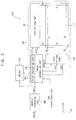
- FIG. 1 is a block diagram illustrating a display system according to an exemplary embodiment of the present inventive concept.
- the display system 100 may include a display apparatus 101 , a graphic processing part 160 and a memory 170 .
- the display apparatus 101 may include a display panel 110 , a gate driving part 130 e.g. gate driving unit), a data driving part 140 (e.g. data driving unit) and a timing controlling part 150 (e.g. timing controller).
- a gate driving part 130 e.g. gate driving unit
- a data driving part 140 e.g. data driving unit
- a timing controlling part 150 e.g. timing controller
- Each of the gate driving part 130 , data driving part 140 and timing controlling part 150 comprise hardware and each part may have more than one possible structural arrangement.
- the gate driving part 130 may comprise a gate driver or a gate driving circuit.
- the data driving part 140 may comprise, for example, a data driver or a data driving circuit.
- the timing controlling part 150 may comprise, for example, a timing controller or a timing control circuit. All of the aforementioned data driving part, gate driving part, and timing controlling part may be realized, for example, by one or more integrated circuits.
- the display panel 110 receives a data signal DS from the data driving part 140 to display an image in conjunction with the gate driving part 130 receiving gate signals.
- the display panel 110 includes gate lines GL that receive gate signals GS, data lines DL that receive data signals, and pixels (not shown).
- the gate lines GL are arranged in a first direction D 1 (shown in FIG. 1 ) and extend in a second direction D 2 substantially perpendicular to the first direction D 1 .
- the plurality of gate lines GL are arranged from left to right (or vice versa) and each gate line GL extends in a direction substantially perpendicular to the arrangement of the gate lines.
- the data lines DL are arranged in the second direction D 2 and extend in the first direction D 1 .
- the first direction D 1 may be parallel to a long side of the display panel 110
- the second direction D 2 may be parallel to a short side of the display panel 110 .
- the display panel 110 may be a liquid crystal display (LCD) panel including a liquid crystal.
- the display panel 110 may be constructed as a touch display panel capable of sensing a touch.
- a touch display panel may be capable of detecting “near-touch” proximity-based touch sensing.
- the touch display panel is not limited to, for example, a capacitive type touch display, and it is within the inventive concept that a type of the touch display panel may comprise any of a resistive, a surface acoustic wave (SAW), or an infrared type.
- SAW surface acoustic wave
- the gate driving part 130 , the data driving part 140 and the timing controlling part 150 shown in FIG. 1 may be considered to comprise a display panel driving apparatus for driving the display panel 110 .
- the inventive concept is not limited to such a configuration.
- the gate driving part 130 may be disposed adjacent the long side of the display panel 110 .
- the gate driving part 130 generates the gate signals GS in response to a vertical start signal STV and a first clock signal CLK 1 provided from the timing controlling part 150 , and outputs the gate signals GS to the gate lines GL.
- the gate driving part 130 may include, for example, a gate driver or a gate driving circuit.
- the data driving part 140 is disposed adjacent the short side of the display panel 110 .
- the data driving part 140 receives pivot image data PVDATA from the timing controlling part 150 , generates the data signal DS based on the pivot image data PVDATA, and outputs the data signal DS to the data line DL in response to a horizontal start signal STH and a second clock signal CLK 2 provided from the timing controlling part 150 .
- the data driving part 140 may include a data driver or a data driving circuit.
- the timing controlling part 150 receives the pivot image data PVDATA from the graphic processing part 160 , and receives a control signal CON from an external source or component.
- the control signal CON may include a horizontal synchronous signal Hsync, a vertical synchronous signal Vsync and a clock signal CLK.
- the timing controlling part 150 generates the horizontal start signal STH using the horizontal synchronous signal Hsync and outputs the horizontal start signal STH to the data driving part 140 .
- the timing controlling part 150 generates the vertical start signal STV using the vertical synchronous signal Vsync and outputs the vertical start signal STV to the gate driving part 130 .
- the timing controlling part 150 generates the first clock signal CLK 1 and the second clock signal CLK 2 based on receiving the clock signal CLK as part of the control signal CON, outputs the first clock signal CLK 1 to the gate driving part 130 , and outputs the second clock signal CLK 2 to the data driving part 140 .
- the timing controlling part 150 may include a timing controller or a timing controlling circuit.
- the graphic processing part 160 receives image data IDATA.
- the graphic processing part 160 processes the image data IDATA.
- the graphic processing part 160 includes a pivot performing part 161 .
- the pivot performing part 161 performs a pivot function which rotates the display of the image, for example, by about 90 degrees on the image data IDATA, and outputs the pivoted image data PVDATA to the timing controlling part 150 .
- the graphic processing part 160 may perform the pivot function in response to a pivot request data PVR received from the display apparatus 101 .
- the pivot request data PVR may be part of an Extended Display Identification Data (EDID).
- the graphic processing part 160 may receive, from the memory 170 , the image data IDATA stored in the memory 170 , and may perform the pivot function on the image data IDATA.
- the graphic processing part 160 may include at least one of a graphic processor, a graphic processing unit and a graphic processing circuit.
- the pivot performing part 161 may include a pivot circuit for performing the pivot function.
- the memory 170 receives the image data IDATA and stores the image data IDATA.
- FIG. 2 is a flowchart illustrating an example of a method of driving the display system 100 of FIG. 1 .
- a person of ordinary skill in the art should understand and appreciate that the inventive concept is not limited to the operations in the flowchart.
- the graphic processing part 160 receives the pivot request data PVR from the display apparatus 101 . More specifically, the graphic processing part 160 receives the pivot request data PVR from the display apparatus 101 including the display panel 110 , the gate driving part 130 , the data driving part 140 and the timing controlling part 150 .
- the pivot request data PVR may be, for example, an Extended Display Identification Data (EDID) or a part of the EDID.
- EDID Extended Display Identification Data
- the graphic processing part 160 performs the pivot function on the image data IDATA and outputs the pivot image data PVDATA to the timing controlling part 150 . More specifically, the graphic processing part 160 includes the pivot performing part 161 .
- the pivot performing part 161 performs the pivot function which rotates the image by about 90 degrees on the image data IDATA, and outputs the pivot image data PVDATA.
- the graphic processing part 160 may perform the pivot function in response to the pivot request data PVR being received from the display apparatus 101 .
- the graphic processing part 160 may receive, from the memory 170 , the image data IDATA stored in the memory 170 , and may perform the pivot function on the image data IDATA.
- the data driving part 140 outputs the data signal DS based on the pivot image data PVDATA to the data lines DL of the display panel 110 . More specifically, the graphic processing part 160 outputs the pivot image data PVDATA to the timing controlling part 150 . The timing controlling part 150 outputs the pivot image data PVDATA to the data driving part 140 . The data driving part 140 receives the pivot image data PVDATA from the timing controlling part 150 , generates the data signal DS based on the pivot image data PVDATA, and outputs the data signal DS to the data lines DL in response to the horizontal start signal STH and the second clock signal CLK 2 provided from the timing controlling part 150 .
- the gate driving part 130 outputs the gate signal GS to the gate line GL of the display panel 110 . Specifically, the gate driving part 130 generates the gate signals GS in response to the vertical start signal STV and the first clock signal CLK 1 provided from the timing controlling part 150 , and outputs the gate signals GS to the gate lines GL.
- the number of data driving integrated circuits included in the data driving part 140 may be decreased. Accordingly, a manufacturing cost of the display apparatus 101 may be decreased.
- the graphic processing part 160 performs the pivot function in response to the pivot request data PVR output from the display apparatus 101 , and thus the graphic processing part 160 may perform the pivot function without an instruction from an external operating system.
- FIG. 3 is a block diagram illustrating a display system according to an exemplary embodiment of the present inventive concept.
- the display system 200 according to the present exemplary embodiment illustrated in FIG. 3 may be substantially similar to the display system 100 according to the previous exemplary embodiment illustrated in FIG. 1 , except for a display apparatus 201 , a timing controlling part 250 , a graphic processing part 260 and a memory 270 .
- a display apparatus 201 a timing controlling part 250 , a graphic processing part 260 and a memory 270 .
- the same reference numerals will be used to refer to the same or similar parts as those described in the previous exemplary embodiment and any further repetitive explanation concerning the above elements will be omitted.
- the display system 200 includes the display apparatus 201 , the graphic processing part 260 and the memory 270 .
- the pivot performing part 251 in FIG. 3 is arranged as part of the timing control part 250 , rather than being included in the graphics processing part 160 as shown in FIG. 1 .
- the gate driving part 130 is disposed adjacent the long side of the display panel 110 .
- the gate driving part 130 generates the gate signals GS in response to the vertical start signal STV and the first clock signal CLK 1 provided from the timing controlling part 250 , and outputs the gate signals GS to the gate lines GL.
- the data driving part 140 is disposed adjacent the short side of the display panel 110 .
- the data driving part 140 receives the pivot image data PVDATA from the timing controlling part 250 , generates the data signal DS based on the pivot image data PVDATA, and outputs the data signal DS to the data line DL in response to the horizontal start signal STH and the second clock signal CLK 2 provided from the timing controlling part 250 .
- the timing controlling part 250 receives the image data IDATA from the graphic processing part 260 , and receives the control signal CON from an external component or source.
- the control signal CON may include, for example, the horizontal synchronous signal Hsync, the vertical synchronous signal Vsync and the clock signal CLK.
- the timing controlling part 250 generates the horizontal start signal STH using the horizontal synchronous signal Hsync and outputs the horizontal start signal STH to the data driving part 140 .
- the timing controlling part 250 generates the vertical start signal STV using the vertical synchronous signal Vsync and outputs the vertical start signal STV to the gate driving part 130 .
- the timing controlling part 250 generates the first clock signal CLK 1 and the second clock signal CLK 2 using the clock signal CLK, outputs the first clock signal CLK 1 to the gate driving part 130 , and outputs the second clock signal CLK 2 to the data driving part 140 .
- the timing controlling part 250 includes a pivot performing part 251 .
- the pivot performing part may include a pivot circuit that performs the pivot function, and such structure may be arranged in the timing controlling part 250 shown in FIG. 3 .
- the pivot performing part 251 performs the pivot function on the image data IDATA, and outputs the pivot image data PVDATA to the data driving part 140 .
- the timing controlling part 250 may receive, from the memory 270 , the image data IDATA stored in the memory 270 , and may perform the pivot function on the image data IDATA.
- the graphic processing part 260 receives the image data IDATA and outputs the image data IDATA to the timing controlling part 250 .
- the graphic processing part 260 shown in FIG. 3 may be omitted.
- the timing controlling part 250 may receive the image data IDATA from the external source or component, rather than via the graphic processing part 260 .
- the memory 270 receives the image data IDATA and stores the image data IDATA.
- the memory 270 may receive the image data IDATA from the graphic processing part 260 or from the external source or component.
- FIG. 4 is a flowchart illustrating a method of driving the display system 200 of FIG. 3 .
- the timing controlling part 250 performs the pivot function on the image data IDATA and outputs the pivot image data PVDATA to the data driving part 140 .
- the timing controlling part 250 may includes the pivot performing part 251 .
- the pivot performing part 251 performs the pivot function on the image data IDATA, and outputs the pivot image data PVDATA to the data driving part 140 .
- the timing controlling part 250 may receive, from the memory 270 , the image data IDATA stored in the memory 270 , and may perform the pivot function on the image data IDATA.
- the data driving part 140 outputs the data signal DS based on the pivot image data PVDATA to the data line DL of the display panel 110 .
- the data driving part 140 receives the pivot image data PVDATA from the timing controlling part 250 , generates the data signal DS based on the pivot image data PVDATA, and outputs the data signal DS to the data line DL in response to the horizontal start signal STH and the second clock signal CLK 2 provided from the timing controlling part 250 .
- the gate driving part 130 outputs the gate signal GS to the gate line GL of the display panel 110 . More specifically, the gate driving part 130 generates the gate signals GS in response to the vertical start signal STV and the first clock signal CLK 1 provided from the timing controlling part 250 , and outputs the gate signals GS to the gate lines GL.
- the number of data driving integrated circuits included in the data driving part 140 may be decreased.
- a manufacturing cost of the display apparatus 201 may be decreased.
- timing controlling part 250 performs the pivot function, and thus the timing controlling part 250 may perform the pivot function without an instruction from an external operating system. Thus, a delay time of an image display may be decreased.
- FIG. 5 is a block diagram illustrating a display system according to an exemplary embodiment of the present inventive concept.
- the display system 300 according to the present exemplary embodiment illustrated in FIG. 5 may be substantially the same as the display system 100 according to the previous exemplary embodiment illustrated in FIG. 1 except for a display apparatus 301 , a display panel 310 , a data driving part 340 , a timing controlling part 350 and a graphic processing part 360 .
- a display apparatus 301 a display apparatus 301 , a display panel 310 , a data driving part 340 , a timing controlling part 350 and a graphic processing part 360 .
- the same reference numerals will be used to refer to same or like parts as those described in the previous exemplary embodiment and any further repetitive explanation concerning the above elements will be omitted.
- the display system 300 includes the display apparatus 301 , the graphic processing part 360 and the memory 170 .
- the display apparatus 301 includes the display panel 310 , the gate driving part 130 , the data driving part 340 and the timing controlling part 350 .
- the display panel includes a touch display.
- the display panel 310 may be substantially the same as the display panel 110 according to the previous exemplary embodiment illustrated in FIG. 1 .
- the display panel 310 receives the data signal DS from the data driving part 340 to display an image, and the data driving part is arranged adjacent a short side of the display panel 310 .
- the display panel 310 may be a touch display panel capable of sensing a touch.
- the display panel 310 outputs touch data TDATA to the graphic processing part 360 when a touch is generated on the display panel 310 .
- the gate driving part 130 , the data driving part 340 and the timing controlling part 350 may be defined as a display panel driving apparatus for driving the display panel 310 .
- the gate driving part 130 is disposed adjacent a long side of the display panel 310 , similar to the configurations in FIGS. 1 and 3 .
- the gate driving part 130 generates the gate signals GS in response to the vertical start signal STV and the first clock signal CLK 1 provided from the timing controlling part 350 , and outputs the gate signals GS to the gate lines GL.
- the data driving part 340 is disposed adjacent a short side of the display panel 310 .
- the data driving part 340 receives the pivot image data PVDATA from the timing controlling part 350 , generates the data signal DS based on the pivot image data PVDATA, and outputs the data signal DS to the data line DL in response to the horizontal start signal STH and the second clock signal CLK 2 provided from the timing controlling part 350 .
- the timing controlling part 350 receives the pivot image data PVDATA output from the graphic processing part 360 , and receives the control signal CON from an external source or component.
- the control signal CON may include the horizontal synchronous signal Hsync, the vertical synchronous signal Vsync and the clock signal CLK.
- the timing controlling part 350 generates the horizontal start signal STH using the horizontal synchronous signal Hsync and outputs the horizontal start signal STH to the data driving part 340 .
- the timing controlling part 350 generates the vertical start signal STV using the vertical synchronous signal Vsync and outputs the vertical start signal STV to the gate driving part 130 .
- the timing controlling part 350 generates the first clock signal CLK 1 and the second clock signal CLK 2 using the clock signal CLK received via the control signal, outputs a first clock signal CLK 1 to the gate driving part 130 , and outputs a second clock signal CLK 2 to the data driving part 340 .
- the graphic processing part 360 includes a touch data processing part 362 and a pivot performing part 361 .
- the touch data processing part 362 receives the touch data TDATA from the display panel 310 .
- the touch data processing part 362 processes the touch data TDATA and outputs touch process data TPDATA for displaying an image related to the touch on the display panel 310 .
- the TPDATA output by the touch data processing part 362 is received by the timing control part 350 , and is in turn output to the data driving part 340 .
- the pivot performing part 361 performs the pivot function which rotates the image by about 90 degrees on the image data IDATA, and outputs the pivot image data PVDATA to the timing controlling part 350 .
- the pivot image data PVDATA may include the touch process data TPDATA.
- the graphic processing part 360 may perform the pivot function in response to the touch data TDATA received from the display apparatus 301 .
- the touch data TDATA may be in the pivot request data PVR according to the previous exemplary embodiment illustrated in FIG. 1 .
- the graphic processing part 360 may receive, from the memory 170 , the image data IDATA stored in the memory 170 , and may perform the pivot function on the image data IDATA.
- FIG. 6 is a flowchart illustrating a method of driving the display system 300 of FIG. 5 .
- the graphic processing part 360 receives the touch data TDATA from the display panel 310 .
- the display panel 310 outputs the touch data TDATA indicating a sense of the touch when the touch is generated on the display panel 310 .
- the touch data processing part 362 of the graphic processing part 360 receives the touch data TDATA from the display panel 310 .
- the graphic processing part 360 processes the touch data TDATA, performs the pivot function on the image data IDATA in response to the touch data TDATA, and outputs the pivot image data PVDATA. More specifically, in this configuration the graphic processing part 360 includes the touch data processing part 362 and the pivot performing part 361 .
- the touch data processing part 362 processes the touch data TDATA and outputs the touch process data TPDATA for displaying the image related to the touch on the display panel 310 .
- the pivot performing part 361 performs the pivot function on the image data IDATA, and outputs the pivot image data PVDATA to the timing controlling part 350 .
- the pivot image data PVDATA may include the touch process data TPDATA.
- the graphic processing part 360 may perform the pivot function in response to the touch data TDATA received from the display apparatus 301 .
- the graphic processing part 360 may receive, from the memory 170 , the image data IDATA stored in the memory 170 , and may perform the pivot function on the image data IDATA.
- the data driving part 340 outputs the data signal DS based on the pivot image data PVDATA to the data line DL of the display panel 310 . More specifically, the data driving part 340 receives the pivot image data PVDATA from the timing controlling part 350 , generates the data signal DS based on the pivot image data PVDATA, and outputs the data signal DS to the data line DL in response to the horizontal start signal STH and the second clock signal CLK 2 provided from the timing controlling part 350 .
- the gate driving part 130 outputs the gate signal GS to the gate line GL of the display panel 310 . More specifically, the gate driving part 130 generates the gate signals GS in response to the vertical start signal STV and the first clock signal CLK 1 provided from the timing controlling part 350 , and outputs the gate signals GS to the gate lines GL.
- FIG. 7 is a block diagram illustrating a display system according to an exemplary embodiment of the present inventive concept.
- the display system 400 according to the present exemplary embodiment illustrated in FIG. 7 may be substantially similar or the same as the display system 100 according to the configuration illustrated in FIG. 1 except for a display apparatus 401 , a display panel 410 , a data driving part 340 , a timing controlling part 450 , a graphic processing part 260 and a memory 270 .
- a display apparatus 401 a display apparatus 401 , a display panel 410 , a data driving part 340 , a timing controlling part 450 , a graphic processing part 260 and a memory 270 .
- the same reference numerals will be used to refer to same or like parts as those described in the previous exemplary embodiment and any further repetitive explanation concerning the above elements will be omitted.
- the display system 400 includes the display apparatus 401 , the graphic processing part 260 and the memory 270 .
- the display apparatus 401 includes the display panel 410 , the gate driving part 130 , the data driving part 340 and the timing controlling part 450 .
- the display panel 410 may be substantially the same as the display panel 110 according to the previous exemplary embodiment illustrated in FIG. 1 .
- the display panel 410 receives the data signal DS from the data driving part 340 to display an image.
- the display panel 410 may be a touch display panel capable of sensing a touch.
- the display panel 410 outputs, for example, the touch data TDATA to the timing controlling part 450 when a touch is generated on the display panel 410 .
- the gate driving part 130 , the data driving part 340 and the timing controlling part 450 may be defined as a display panel driving apparatus for driving the display panel 410 .
- the gate driving part 130 is disposed adjacent a long side of the display panel 410 .
- the gate driving part 130 generates the gate signals GS in response to the vertical start signal STV and the first clock signal CLK 1 provided from the timing controlling part 450 , and outputs the gate signals GS to the gate lines GL.
- the data driving part 340 is disposed adjacent a short side of the display panel 410 .
- the data driving part 340 receives the pivot image data PVDATA from the timing controlling part 450 , generates the data signal DS based on the pivot image data PVDATA, and outputs the data signal DS to the data line DL in response to the horizontal start signal STH and the second clock signal CLK 2 provided from the timing controlling part 450 .
- the timing controlling part 450 receives the image data IDATA from the graphic processing part 260 , and receives the control signal CON from an external source or component.
- the control signal CON may include the horizontal synchronous signal Hsync, the vertical synchronous signal Vsync and the clock signal CLK.
- the timing controlling part 450 generates the horizontal start signal STH using the horizontal synchronous signal Hsync and outputs the horizontal start signal STH to the data driving part 340 .
- the timing controlling part 450 generates the vertical start signal STV using the vertical synchronous signal Vsync and outputs the vertical start signal STV to the gate driving part 130 .
- the timing controlling part 450 generates the first clock signal CLK 1 and the second clock signal CLK 2 using the clock signal CLK, outputs the first clock signal CLK 1 to the gate driving part 130 , and outputs the second clock signal CLK 2 to the data driving part 340 .
- the timing controlling part 450 includes a touch data processing part 452 and a pivot performing part 451 .
- the touch data processing part 452 receives the touch data TDATA from the display panel 410 .
- the touch data processing part 452 processes the touch data TDATA and outputs the touch process data TPDATA for displaying an image related to the touch on the display panel 410 .
- the pivot performing part 451 performs the pivot function which rotates the image by about 90 degrees on the image data IDATA, and outputs the pivot image data PVDATA to the data driving part 340 .
- the pivot image data PVDATA may include the touch process data TPDATA.
- the timing controlling part 450 may performs the pivot function in response to the touch data TDATA received from the display panel 410 .
- the timing controlling part 450 may receive, from the memory 270 , the image data IDATA stored in the memory 270 , and may perform the pivot function on the image data IDATA.
- the graphic processing part 260 receives the image data from an external source, and outputs the image data IDATA to the timing controlling part 450 .
- the graphic processing part 260 may be omitted.
- the timing controlling part 450 may receive the image data IDATA from the external source or an interface instead of the IDATA being first transmitted to the graphic processing part.
- a switch (not shown), which may be software controlled, that can provide the IDATA to the graphic processing part, or bypass the graphic processing part and provide the IDATA to the timing controlling part from the external source or an interface.
- the memory 270 receives the image data IDATA and stores the image data IDATA.
- the memory 270 may receive the image data IDATA from the graphic processing part 260 or the outside.
- FIG. 8 is a flowchart illustrating a method of driving the display system 400 of FIG. 7 .
- the timing controlling part 450 receives the touch data TDATA from the display panel 410 .
- the display panel 410 may have sensing lines in (e.g. which may be arranged in a grid) that detect a location of a touch generated in a display area, for example, by a finger or a stylus, and outputs a data signal comprising the touch data TDATA,
- the touch data processing part 452 of the timing controlling part 450 receives the touch data TDATA from the display panel 410 .
- the timing controlling part 450 processes the touch data TDATA, performs the pivot function on the image data IDATA in response to the touch data TDATA, and outputs the pivot image data PVDATA.
- the timing controlling part 450 includes the touch data processing part 452 and the pivot performing part 451 .
- the touch data processing part 452 processes the touch data TDATA and outputs the touch process data TPDATA for displaying the image related to the touch on the display panel 410 .
- the pivot performing part 451 performs the pivot function on the image data IDATA, and outputs the pivot image data PVDATA to the data driving part 340 .
- the pivot image data PVDATA may include the touch process data TPDATA.
- the timing controlling part 450 may performs the pivot function in response to the touch data TDATA received from the display panel 410 .
- the timing controlling part 450 may receive, from the memory 270 , the image data IDATA stored in the memory 270 , and may perform the pivot function on the image data IDATA.
- the data driving part 340 outputs the data signal DS based on the pivot image data PVDATA to the data line DL of the display panel 410 .
- the data driving part 340 receives the pivot image data PVDATA from the timing controlling part 450 , generates the data signal DS based on the pivot image data PVDATA, and outputs the data signal DS to the data line DL in response to the horizontal start signal STH and the second clock signal CLK 2 provided from the timing controlling part 450 .
- the gate driving part 130 outputs the gate signal GS to the gate line GL of the display panel 410 . Specifically, the gate driving part 130 generates the gate signals GS in response to the vertical start signal STV and the first clock signal CLK 1 provided from the timing controlling part 450 , and outputs the gate signals GS to the gate lines GL.
- the data driving part 340 since the data driving part 340 is disposed adjacent the short side of the display panel 410 , the number of data driving integrated circuits included in the data driving part 340 may be decreased. Thus, a manufacturing cost of the display apparatus 401 may be decreased.
- timing controlling part 450 performs the pivot function of the image, and thus the timing controlling part 450 may perform the pivot function without an instruction from an external operating system. Thus, a delay time of an image display may be decreased.
- FIG. 9 is a block diagram illustrating a display system according to an exemplary embodiment of the present inventive concept.
- the display system 500 according to the present exemplary embodiment illustrated in FIG. 9 may be substantially similar or the same as the configuration of the display system 100 according to the previous exemplary embodiment illustrated in FIG. 1 except for a display apparatus 501 , a display panel 510 , a data driving part 540 , a timing controlling part 550 and a graphic processing part 560 .
- a display apparatus 501 a display apparatus 501 , a display panel 510 , a data driving part 540 , a timing controlling part 550 and a graphic processing part 560 .
- the same reference numerals will be used to refer to the same or similar parts as those described in the previous exemplary embodiment and any further repetitive explanation concerning the above elements may be omitted.
- the display system 500 may include the display apparatus 501 , the graphic processing part 560 and the memory 170 .
- the display apparatus 501 includes the display panel 510 , the gate driving part 130 , the data driving part 540 and the timing controlling part 550 .
- the display panel 510 may be substantially the same as the display panel 110 according to the previous exemplary embodiment illustrated in FIG. 1 .
- the display panel 510 receives the data signal DS from the data driving part 540 to display an image.
- the display panel 510 may be a touch display panel capable of sensing a touch.
- the display panel 510 outputs the touch data TDATA to the graphic processing part 560 and the timing controlling part 550 when a touch is generated on the display panel 510 .
- the gate driving part 130 , the data driving part 540 and the timing controlling part 550 may be collectively referred to as a display panel driving apparatus for driving the display panel 510 .
- the gate driving part 130 is disposed adjacent a long side of the display panel 510 .
- the gate driving part 130 generates the gate signals GS in response to the vertical start signal STV and the first clock signal CLK 1 provided from the timing controlling part 550 , and outputs the gate signals GS to the gate lines GL.
- the data driving part 540 is disposed adjacent a short side of the display panel 510 .
- the data driving part 540 receives the second pivot image data PVDATA 2 from the timing controlling part 550 , generates the data signal DS based on the second pivot image data PVDATA 2 , and outputs the data signal DS to the data line DL in response to the horizontal start signal STH and the second clock signal CLK 2 provided from the timing controlling part 550 .
- the timing controlling part 550 receives first pivot image data PDATA 1 from the graphic processing part 560 , and receives the control signal CON from an external source or component.
- the control signal CON may include the horizontal synchronous signal Hsync, the vertical synchronous signal Vsync and the clock signal CLK.
- the timing controlling part 550 generates the horizontal start signal STH using the horizontal synchronous signal Hsync and outputs the horizontal start signal STH to the data driving part 540 .
- the timing controlling part 550 generates the vertical start signal STV using the vertical synchronous signal Vsync and outputs the vertical start signal STV to the gate driving part 130 .
- the timing controlling part 550 generates the first clock signal CLK 1 and the second clock signal CLK 2 using the clock signal CLK, outputs the first clock signal CLK 1 to the gate driving part 130 , and outputs the second clock signal CLK 2 to the data driving part 540 .
- the timing controlling part 550 includes a touch data processing part 552 .
- the touch data processing part 552 receives the touch data TDATA from the display panel 510 .
- the touch data processing part 552 processes the touch data TDATA and outputs the touch process data TPDATA for displaying an image related to the touch on the display panel 510 .
- the second pivot image data PVDATA 2 output from the timing controlling part 550 may include first pivot image data PVDATA 1 and the touch process data TPDATA.
- the graphic processing part 560 includes a pivot performing part 561 .
- the pivot performing part 561 performs the pivot function which rotates the image by about 90 degrees on the image data IDATA, and outputs the first pivot image data PVDATA 1 to the timing controlling part 550 .
- the graphic processing part 560 may performs the pivot function in response to the touch data TDATA received from the display apparatus 501 . Accordingly, the touch data TDATA may be in the pivot request data PVR according to a previous exemplary embodiment.
- the graphic processing part 560 may receive, from the memory 170 , the image data IDATA stored in the memory 170 , and may perform the pivot function on the image data IDATA.
- FIG. 10 is a flowchart illustrating a method of driving the display system 500 of FIG. 9 .
- the graphic processing part 560 and the timing controlling part 550 receives the touch data TDATA from the display panel 510 . More specifically, the display panel 510 outputs the touch data TDATA indicating a sense of the touch when the touch is generated on the display panel 510 .
- the pivot performing part 561 of the graphic processing part 560 receives the touch data TDATA from the display panel 510 , and the touch data processing part 552 of the timing controlling part 550 receives the touch data TDATA from the display panel 510 .
- the graphic processing part 560 performs the pivot function on the image data IDATA in response to the touch data TDATA, and outputs the first pivot image data PVDATA 1 . More specifically, the graphic processing part 560 includes the pivot performing part 561 . The pivot performing part 561 performs the pivot function on the image data IDATA, and outputs the first pivot image data PVDATA 1 to the timing controlling part 550 . The graphic processing part 560 may performs the pivot function in response to the touch data TDATA received from the display apparatus 501 . The graphic processing part 560 may receive, from the memory 170 , the image data IDATA stored in the memory 170 , and may perform the pivot function on the image data IDATA.
- the timing controlling part 550 receives the first pivot image data PVDATA 1 , processes the touch data TDATA, and outputs the second pivot image data PVDATA 2 including the touch process data TPDATA. More specifically, the timing controlling part 550 includes the touch data processing part 552 .
- the touch data processing part 552 receives the touch data TDATA from the display panel 510 .
- the touch data processing part 552 processes the touch data TDATA and outputs the touch process data TPDATA for displaying the image related to the touch on the display panel 510 .
- the second pivot image data PVDATA 2 output from the timing controlling part 550 may include first pivot image data PVDATA 1 and the touch process data TPDATA.
- the data driving part 540 outputs the data signal DS based on the second pivot image data PVDATA 2 to the data line DL of the display panel 510 . More specifically, the data driving part 540 receives the second pivot image data PVDATA 2 from the timing controlling part 550 , generates the data signal DS based on the second pivot image data PVDATA 2 , and outputs the data signal DS to the data line DL in response to the horizontal start signal STH and the second clock signal CLK 2 provided from the timing controlling part 550 .
- the gate driving part 130 outputs the gate signal GS to the gate line GL of the display panel 510 . More specifically, the gate driving part 130 generates the gate signals GS in response to the vertical start signal STV and the first clock signal CLK 1 provided from the timing controlling part 550 , and outputs the gate signals GS to the gate lines GL.
- the data driving part 540 since the data driving part 540 is disposed adjacent the short side of the display panel 510 , the number of data driving integrated circuits included in the data driving part 540 may be decreased. Thus, a manufacturing cost of the display apparatus 501 may be decreased.
- the graphic processing part 560 performs the pivot function and the timing controlling part 550 processes the touch data TDATA, and thus a load of the graphic processing part 560 may be decreased. Thus, a delay time of an image display may be decreased.
- FIG. 11 is a block diagram illustrating a display system according to an exemplary embodiment of the present inventive concept.
- the display system 600 according to the present exemplary embodiment illustrated in FIG. 11 may be substantially similar or the same as the display system 100 according to the previous exemplary embodiment illustrated in FIG. 1 except for a display apparatus 601 , a display panel 510 , a data driving part 340 , a timing controlling part 650 , a graphic processing part 660 and a memory 670 .
- a display apparatus 601 a display apparatus 601 , a display panel 510 , a data driving part 340 , a timing controlling part 650 , a graphic processing part 660 and a memory 670 .
- the same reference numerals will be used to refer to same or similar parts as those described in the previous exemplary embodiment and any further repetitive explanation concerning the above elements may be omitted.
- the display system 600 includes the display apparatus 601 , the graphic processing part 660 and the memory 670 .
- the display apparatus 601 includes the display panel 510 , the gate driving part 130 , the data driving part 340 and the timing controlling part 650 .
- the display panel 510 may be substantially the same as the display panel 110 according to the previous exemplary embodiment illustrated in FIG. 1 .
- the display panel 510 receives the data signal DS from the data driving part 340 to display an image.
- the display panel 510 may be a touch display panel capable of sensing a touch.
- the display panel 510 outputs the touch data TDATA to the graphic processing part 660 and the timing controlling part 650 when a touch is generated on the display panel 510 .
- the gate driving part 130 , the data driving part 340 and the timing controlling part 650 may be collectively referred to as a display panel driving apparatus for driving the display panel 510 .
- the gate driving part 130 is disposed adjacent a long side of the display panel 510 .
- the gate driving part 130 generates the gate signals GS in response to the vertical start signal STV and the first clock signal CLK 1 provided from the timing controlling part 650 , and outputs the gate signals GS to the gate lines GL.
- the data driving part 340 is disposed adjacent a short side of the display panel 510 .
- the data driving part 340 receives pivot image data PVDATA from the timing controlling part 650 , generates the data signal DS based on the pivot image data PVDATA, and outputs the data signal DS to the data line DL in response to the horizontal start signal STH and the second clock signal CLK 2 provided from the timing controlling part 650 .
- the timing controlling part 650 receives the touch process data TPDATA from the graphic processing part 660 , and receives the control signal CON from an external source or component.
- the control signal CON may include the horizontal synchronous signal Hsync, the vertical synchronous signal Vsync and the clock signal CLK.
- the timing controlling part 650 generates the horizontal start signal STH using the horizontal synchronous signal Hsync and outputs the horizontal start signal STH to the data driving part 340 .
- the timing controlling part 650 generates the vertical start signal STV using the vertical synchronous signal Vsync and outputs the vertical start signal STV to the gate driving part 130 .
- the timing controlling part 650 generates the first clock signal CLK 1 and the second clock signal CLK 2 using the clock signal CLK, outputs the first clock signal CLK 1 to the gate driving part 130 , and outputs the second clock signal CLK 2 to the data driving part 340 .
- the timing controlling part 650 includes a pivot performing part 651 .
- the pivot performing part 651 performs the pivot function which rotates the image by about 90 degrees on the touch process data TPDATA, and outputs the pivot image data PVDATA to the data driving part 340 .
- the timing controlling part 650 may perform the pivot function in response to the touch data TDATA received from the display panel 510 .
- the timing controlling part 650 may receive, from the memory 670 , the touch process data TPDATA stored in the memory 670 , and may perform the pivot function on the touch process data TPDATA. Accordingly, the pivot image data PVDATA output from the timing controlling part 650 may include the touch process data TPDATA.
- the memory 670 receives the touch process data TPDATA and stores the touch process data TPDATA.
- the memory 670 receives the touch process data TPDATA from the graphic processing part 660 , and stores the touch process data TPDATA.
- the graphic processing part 660 includes a touch data processing part 662 .
- the touch data processing part 662 receives the touch data TDATA from the display panel 510 .
- the touch data processing part 662 processes the touch data TDATA and outputs the touch process data TPDATA for displaying an image related to the touch on the display panel 510 .
- FIG. 12 is a flowchart illustrating a method of driving the display system 600 of FIG. 11 .
- the graphic processing part 660 and the timing controlling part 650 receives the touch data TDATA from the display panel 510 . More specifically, the display panel 510 outputs the touch data TDATA indicating a sense of the touch when the touch is generated on the display panel 510 .
- the touch data processing part 662 of the graphic processing part 660 receives the touch data TDATA from the display panel 510
- the pivot performing part 651 of the timing controlling part 650 receives the touch data TDATA from the display panel 510 .
- the graphic processing part 660 processes the touch data TDATA and outputs the touch process data TPDATA. More specifically, the graphic processing part 660 includes the touch data processing part 662 .
- the touch data processing part 662 processes the touch data TDATA and outputs the touch process data TPDATA for displaying the image related to the touch on the display panel 510 .
- the timing controlling part 650 receives the touch process data TPDATA, performs the pivot function on the touch process data TPDATA in response to the touch data TDATA, and outputs the pivot image data PVDATA. More specifically, the timing controlling part 650 includes the pivot performing part 651 . The pivot performing part 651 performs the pivot function on the touch process data TPDATA, and outputs the pivot image data PVDATA to the data driving part 340 . The timing controlling part 650 may perform the pivot function in response to the touch data TDATA received from the display panel 510 . The timing controlling part 650 may receive, from the memory 670 , the touch process data TPDATA stored in the memory 670 , and may perform the pivot function on the touch process data TPDATA. Thus, the pivot image data PVDATA output from the timing controlling part 650 may include the touch process data TPDATA.
- the data driving part 340 outputs the data signal DS based on the pivot image data PVDATA to the data line DL of the display panel 510 . More specifically, the data driving part 340 receives the pivot image data PVDATA from the timing controlling part 650 , generates the data signal DS based on the pivot image data PVDATA, and outputs the data signal DS to the data line DL in response to the horizontal start signal STH and the second clock signal CLK 2 provided from the timing controlling part 650 .
- the gate driving part 130 outputs the gate signal GS to the gate line GL of the display panel 510 . More specifically, the gate driving part 130 generates the gate signals GS in response to the vertical start signal STV and the first clock signal CLK 1 provided from the timing controlling part 650 , and outputs the gate signals GS to the gate lines GL.
- the number of data driving integrated circuits included in the data driving part 340 may be decreased.
- a manufacturing cost of the display apparatus 601 may be decreased.
- the graphic processing part 660 processes the touch data TDATA and the timing controlling part 650 performs the pivot function, and thus a load of the graphic processing part 660 may be decreased. Thus, a delay time of an image display may be decreased by having the timing controlling part perform the pivot function.
- FIG. 13 is a block diagram illustrating a display system according to an exemplary embodiment of the present inventive concept.
- the display system 700 according to the present exemplary embodiment illustrated in FIG. 13 may be substantially similar or the same as the display system 100 according to the previous exemplary embodiment illustrated in FIG. 1 except for a display apparatus 701 , a data driving part 740 , a timing controlling part 750 , a graphic processing part 760 , a first memory 770 and a second memory 780 .
- a display apparatus 701 a data driving part 740 , a timing controlling part 750 , a graphic processing part 760 , a first memory 770 and a second memory 780 .
- the same reference numerals will be used to refer to same or similar parts as those described in the previous exemplary embodiment and any further repetitive explanation concerning the above elements may be omitted.
- the display system 700 may include the display apparatus 701 , the graphic processing part 760 , the first memory 770 and the second memory 780 .
- the display apparatus 701 includes the display panel 110 , the gate driving part 130 , the data driving part 740 and the timing controlling part 750 .
- the gate driving part 130 , the data driving part 740 and the timing controlling part 750 may be collectively referred to as a display panel driving apparatus for driving the display panel 110 .
- the gate driving part 130 is disposed adjacent a long side of the display panel 110 .
- the gate driving part 130 generates the gate signals GS in response to the vertical start signal STV and the first clock signal CLK 1 provided from the timing controlling part 750 , and outputs the gate signals GS to the gate lines GL.
- the data driving part 740 is disposed adjacent a short side of the display panel 110 .
- the data driving part 740 receives second pivot image data PVDATA 2 from the timing controlling part 750 , generates the data signal DS based on the second pivot image data PVDATA 2 , and outputs the data signal DS to the data line DL in response to the horizontal start signal STH and the second clock signal CLK 2 provided from the timing controlling part 750 .
- the graphic processing part 760 receives the image data IDATA from an external source of component.
- the graphic processing part 760 includes a first pivot performing part 761 .
- the first pivot performing part 761 performs a first pivot function on the image data IDATA, and outputs first pivot image data PVDATA 1 to the timing controlling part 750 .
- the performance of the first pivot function may be a performance of the pivot function on only some (e.g. part) of the image data IDATA.
- the graphic processing part 760 may perform the first pivot function in response to the pivot request data PVR received from the display apparatus 701 .
- the pivot request data PVR may be an Extended Display Identification Data (EDID).
- the graphic processing part 760 may receive, from the memory 770 , the image data IDATA stored in the first memory 770 , and may perform the first pivot function on the image data IDATA.
- EDID Extended Display Identification Data
- the first memory 770 receives the image data IDATA and stores the image data IDATA.
- the timing controlling part 750 receives the first pivot image data PVDATA 1 from the graphic processing part 760 , and receives the control signal CON from an outside.
- the control signal CON may include the horizontal synchronous signal Hsync, the vertical synchronous signal Vsync and the clock signal CLK.
- the timing controlling part 750 generates the horizontal start signal STH using the horizontal synchronous signal Hsync and outputs the horizontal start signal STH to the data driving part 740 .
- the timing controlling part 750 generates the vertical start signal STV using the vertical synchronous signal Vsync and outputs the vertical start signal STV to the gate driving part 130 .
- the timing controlling part 750 generates the first clock signal CLK 1 and the second clock signal CLK 2 using the clock signal CLK, outputs the first clock signal CLK 1 to the gate driving part 130 , and outputs the second clock signal CLK 2 to the data driving part 740 .
- the timing controlling part 750 includes a second pivot performing part 751 .
- the second pivot performing part 751 performs a second pivot function on the first pivot image data PVDATA 1 , and outputs the second pivot image data PVDATA 2 to the data driving part 740 .
- the performance of the second pivot function by the second pivot performing part 751 may be a performance of the pivot function on the remainder of the image data IDATA which did not have a pivot function performed by the first pivot performing part 761 .
- the timing controlling part 750 may receive, from the second memory 780 , the first pivot image data PVDATA 1 stored in the second memory 780 , and may perform the second pivot function on the first pivot image data PVDATA 1 .
- FIG. 14 is a flowchart illustrating a method of driving the display system 700 of FIG. 13 .
- the graphic processing part 760 receives the pivot request data PVR from the display apparatus 701 . More specifically, the graphic processing part 760 receives the pivot request data PVR from the display apparatus 701 including the display panel 110 , the gate driving part 130 , the data driving part 740 and the timing controlling part 750 .
- the pivot request data PVR may be an Extended Display Identification Data (EDID).
- the graphic processing part 760 performs the first pivot function on the image data IDATA and outputs the first pivot image data PVDATA 1 . More specifically, the graphic processing part 760 includes the first pivot performing part 761 .
- the first pivot performing part 761 performs the first pivot function on the image data IDATA, and outputs the first pivot image data PVDATA 1 to the timing controlling part 750 .
- the performance of the first pivot function may made on some (but not all) of the image data IDATA.
- the graphic processing part 760 may perform the first pivot function in response to the pivot request data PVR received from the display apparatus 701 .
- the graphic processing part 760 may receive, from the first memory 770 , the image data IDATA stored in the memory 770 , and may perform the first pivot function on the image data IDATA.
- the timing controlling part 750 performs the second pivot function on the first pivot image data PVDATA 1 and outputs the second pivot image data PVDATA 2 . More specifically, the timing controlling part 750 includes the second pivot performing part 751 .
- the second pivot performing part 751 performs the second pivot function on the first pivot image data PVDATA 1 , and outputs the second pivot image data PVDATA 2 to the data driving part 740 .
- the performance of the second pivot function by the second pivot performing part 751 may be made on the remaining image data IDATA as only some of the image data had the first pivot function performed by the first pivot performing part 761 .
- the timing controlling part 750 may receive, from the second memory 780 , the first pivot image data PVDATA 1 stored in the second memory 780 , and may perform the second pivot function on the first pivot image data PVDATA 1 .
- the data driving part 740 outputs the data signal DS based on the second pivot image data PVDATA 2 to the data line DL of the display panel 110 . More specifically, the data driving part 740 receives the second pivot image data PVDATA 2 from the timing controlling part 750 , generates the data signal DS based on the second pivot image data PVDATA 2 , and outputs the data signal DS to the data line DL in response to the horizontal start signal STH and the second clock signal CLK 2 provided from the timing controlling part 750 .
- the gate driving part 130 outputs the gate signal GS to the gate line GL of the display panel 110 . More specifically, the gate driving part 130 generates the gate signals GS in response to the vertical start signal STV and the first clock signal CLK 1 provided from the timing controlling part 750 , and outputs the gate signals GS to the gate lines GL.
- the number of data driving integrated circuits included in the data driving part 740 may be decreased.
- a manufacturing cost of the display apparatus 701 may be decreased.
- a load of the graphic processing part 760 may be decreased by having two components perform the pivot function on portions of the IDATA.
- a delay time of an image display may be decreased.
- FIG. 15 is a block diagram illustrating a display system according to an exemplary embodiment of the present inventive concept.
- the display system 800 according to the present exemplary embodiment illustrated in FIG. 15 may be substantially similar or the same as the display system 100 according to the previous exemplary embodiment illustrated in FIG. 1 except for a display apparatus 801 , a data driving part 840 , a timing controlling part 850 , a graphic processing part 860 , a first memory 870 , a second memory 880 and a pivot controlling part 890 .
- a display apparatus 801 a data driving part 840 , a timing controlling part 850 , a graphic processing part 860 , a first memory 870 , a second memory 880 and a pivot controlling part 890 .
- the same reference numerals will be used to refer to same or similar parts as those described in the previous exemplary embodiment and any further repetitive explanation concerning the above elements may be omitted.
- the display system 800 includes the display apparatus 801 , the graphic processing part 860 , the first memory 870 , the second memory 880 and the pivot controlling part 890 .
- the display apparatus 801 includes the display panel 110 , the gate driving part 130 , the data driving part 840 and the timing controlling part 850 .
- the gate driving part 130 , the data driving part 840 and the timing controlling part 850 may be collectively referred to as a display panel driving apparatus for driving the display panel 110 .
- the gate driving part 130 is disposed adjacent a long side of the display panel 110 .
- the gate driving part 130 generates the gate signals GS in response to the vertical start signal STV and the first clock signal CLK 1 provided from the timing controlling part 850 , and outputs the gate signals GS to the gate lines GL.
- the data driving part 840 is disposed adjacent a short side of the display panel 110 .
- the data driving part 840 receives second image process data PDATA 2 from the timing controlling part 850 , generates the data signal DS based on the second image process data PDATA 2 , and outputs the data signal DS to the data line DL in response to the horizontal start signal STH and the second clock signal CLK 2 provided from the timing controlling part 850 .
- the graphic processing part 860 receives the image data IDATA from an external source or component.
- the graphic processing part 860 performs an image process on the image data IDATA, and outputs first image process data PDATA 1 to the timing controlling part 850 .
- the pivot controlling part 890 controls the graphic processing part 860 and the timing controlling part 850 such that at least one of the processing part 860 and the timing controlling part 850 performs a pivot function on the image data IDATA.
- the pivot controlling part 890 outputs a pivot control signal PCON for controlling the pivot function of the graphic processing part 860 and the timing controlling part 850 , to the graphic processing part 860 and the timing controlling part 850 .
- the pivot controlling part 890 may control the graphic processing part 860 so that the graphic processing part 860 performs the pivot function on the image data IDATA.
- the first image process data PDATA 1 output from the graphic processing part 860 may include pivot image data which is generated by performing the pivot function on the image data IDATA.
- a first pivot performing part 861 in the graphic processing part 860 may perform the pivot function.
- the graphic processing part 860 may receive, from the first memory 870 , the image data IDATA stored in the first memory 870 , and performs the pivot function on the image data IDATA.
- the pivot controlling part 890 may control the graphic processing part 860 and the timing controlling part 850 so that the graphic processing part 860 does not perform the pivot function on the image data IDATA.
- the timing controlling part 850 performs the pivot function on the image data IDATA.
- the first image process data PDATA 1 output from the graphic processing part 860 may not include the pivot image data
- the second image process data PDATA 2 output from the timing controlling part 850 may include the pivot image data generated by performing the pivot function on the image data IDATA.
- the pivot function may be performed according to the load value of the graphic processing part 860 , and the driving frequency of the graphic processing part by the graphic processing part, or the timing controlling part.
- a second pivot performing part 851 in the timing controlling part 850 may perform the pivot function.
- the timing controlling part 850 may receive, from the second memory 880 , the image data IDATA stored in the second memory 880 , and may perform the pivot function on the image data IDATA.
- the pivot controlling part 890 may control the graphic processing part 860 and the timing controlling part 850 so that the graphic processing part 860 performs the pivot function on some (e.g. part) of the image data IDATA and the timing controlling part 850 performs the pivot function on a remainder of the image data IDATA.
- the some of the image data IDATA may be M (M is a natural number) frame of N (N is a natural number not less than two) frames of the image data IDATA, and the remains of the image data IDATA may be (N-M) frame of N frames.
- the first image process data PDATA 1 output from the graphic processing part 860 may include first pivot image data generated by performing a first pivot function on the image data IDATA
- the second image process data PDATA 2 output from the timing controlling part 850 may include second pivot image data generated by performing a second pivot function in addition to the first pivot function on the image data IDATA.
- the pivot controlling part 890 may include a load determining part 891 determining the load and the driving frequency of the graphic processing part 860 .
- the reference frequency compared with the driving frequency of the graphic processing part 860 which is determined by the load determining part 891 may be about 40 Hz.
- the first memory 870 receives the image data IDATA from an external source of component and stores the image data IDATA.
- the second memory 880 receives the image data IDATA from the outside and stores the image data IDATA. In addition, the second memory 880 receives the first image process data PDATA 1 from the graphic processing part 860 and stores the first image process data PDATA 1 .
- FIG. 16 is a flowchart illustrating a method of driving the display system 800 of FIG. 15 .
- the pivot controlling part 890 determines the load of the graphic processing part 860 . More specifically, the pivot controlling part 890 may include the load determining part 891 determining the load and the driving frequency of the graphic processing part 860 .
- the reference frequency which is compared with the driving frequency of the graphic processing part 860 , may be determined by the load determining part 891 .
- the reference frequency may be about 40 Hz.
- the graphic processing part 860 processes the image data IDATA according to the load of the graphic processing part 860 , and outputs the first image process data PDATA 1 .
- the pivot controlling part 890 may control the graphic processing part 860 so that the graphic processing part 860 performs the pivot function on the image data IDATA.
- the first image process data PDATA 1 output from the graphic processing part 860 may include the pivot image data which is generated by performing the pivot function on the image data IDATA.
- the first pivot performing part 861 in the graphic processing part 860 may perform the pivot function.
- the graphic processing part 860 may receive, from the first memory 870 , the image data IDATA stored in the first memory 870 , and performs the pivot function on the image data IDATA.
- the pivot controlling part 890 may control the graphic processing part 860 so that the graphic processing part 860 does not perform the pivot function on the image data IDATA.
- the first image process data PDATA 1 output from the graphic processing part 860 may not include the pivot image data.
- the pivot controlling part 890 may control the graphic processing part 860 so that the graphic processing part 860 performs the pivot function on some (e.g. part) of the image data IDATA.
- some of the image data IDATA may be M (M is a natural number) frame of N (N is a natural number not less than two) frames of the image data IDATA.
- the first image process data PDATA 1 output from the graphic processing part 860 may include the first pivot image data generated by performing the first pivot function on the image data IDATA.
- the timing controlling part 850 processes the first image process data PDATA 1 according to the load of the graphic processing part 860 , and outputs the second image process data PDATA 2 .
- the pivot controlling part 890 may control the timing controlling part 850 so that the timing controlling part 850 performs the pivot function on the image data IDATA.
- the first image process data PDATA 1 output from the graphic processing part 860 may not include the pivot image data
- the second image process data PDATA 2 output from the timing controlling part 850 may include the pivot image data generated by performing the pivot function on the image data IDATA.
- the timing controlling part 850 When the timing controlling part 850 performs the pivot function, the second pivot performing part 851 in the timing controlling part 850 may perform the pivot function. In addition, the timing controlling part 850 may receive, from the second memory 880 , the image data IDATA stored in the second memory 880 , and may perform the pivot function on the image data IDATA.
- the pivot controlling part 890 may control the timing controlling part 850 so that the timing controlling part 850 performs the pivot function on the remainder of the image data IDATA.
- the remains of the image data IDATA may be (N-M) frame of N frames.
- the first image process data PDATA 1 output from the graphic processing part 860 may include the first pivot image data generated by performing the first pivot function on the image data IDATA
- the second image process data PDATA 2 output from the timing controlling part 850 may include the second pivot image data generated by performing the second pivot function in addition to the first pivot function on the image data IDATA.
- the data driving part 840 outputs the data signal DS based on the second image process data PDATA to the data line DL of the display panel 110 .
- the data driving part 840 receives the second image process data PDATA 2 from the timing controlling part 850 , generates the data signal DS based on the second image process data PDATA 2 , and outputs the data signal DS to the data line DL in response to the horizontal start signal STH and the second clock signal CLK 2 provided from the timing controlling part 850 .
- the gate driving part 130 outputs the gate signal GS to the gate line GL of the display panel 110 . Specifically, the gate driving part 130 generates the gate signals GS in response to the vertical start signal STV and the first clock signal CLK 1 provided from the timing controlling part 850 , and outputs the gate signals GS to the gate lines GL.
- the data driving part 840 since the data driving part 840 is disposed adjacent the short side of the display panel 110 , the number of data driving integrated circuits included in the data driving part 840 may be decreased. Thus, a manufacturing cost of the display apparatus 801 may be decreased.
- At least one of the graphic processing part 860 and the timing controlling part 850 performs the pivot function in consideration of the load and the driving frequency of the graphic processing part 860 , a delay time of an image display may be decreased.
- the present inventive concept may be applied to an electronic device having a display apparatus.
- the present inventive concept may be applied to a television, a computer monitor, a laptop, a digital camera, a cellular phone, a smart phone, a tablet Personal Computer (PC), a smart pad, a Personal Digital Assistant (PDA), a Portable Multimedia Player (PMP), an MP3 player, a navigation system, a camcorder, a portable game console, etc., just to name some non-limiting examples.
- PDA Personal Digital Assistant
- PMP Portable Multimedia Player
- MP3 player MP3 player
- navigation system e.g. about 45 degrees, about 180 degrees, about 270 degrees
- the rotation may be in a clockwise or counterclockwise direction.
Landscapes
- Engineering & Computer Science (AREA)
- Theoretical Computer Science (AREA)
- Physics & Mathematics (AREA)
- General Physics & Mathematics (AREA)
- General Engineering & Computer Science (AREA)
- Computer Hardware Design (AREA)
- Human Computer Interaction (AREA)
- Chemical & Material Sciences (AREA)
- Crystallography & Structural Chemistry (AREA)
- Control Of Indicators Other Than Cathode Ray Tubes (AREA)
- Controls And Circuits For Display Device (AREA)
- Liquid Crystal Display Device Control (AREA)
Abstract
Description
Claims (19)
Applications Claiming Priority (2)
| Application Number | Priority Date | Filing Date | Title |
|---|---|---|---|
| KR1020160127535A KR102555347B1 (en) | 2016-10-04 | 2016-10-04 | Display system and method of driving the same |
| KR10-2016-0127535 | 2016-10-04 |
Publications (2)
| Publication Number | Publication Date |
|---|---|
| US20180096647A1 US20180096647A1 (en) | 2018-04-05 |
| US10789876B2 true US10789876B2 (en) | 2020-09-29 |
Family
ID=61757161
Family Applications (1)
| Application Number | Title | Priority Date | Filing Date |
|---|---|---|---|
| US15/702,868 Active 2037-11-29 US10789876B2 (en) | 2016-10-04 | 2017-09-13 | Display system and method of driving the same |
Country Status (2)
| Country | Link |
|---|---|
| US (1) | US10789876B2 (en) |
| KR (1) | KR102555347B1 (en) |
Citations (14)
| Publication number | Priority date | Publication date | Assignee | Title |
|---|---|---|---|---|
| US4929085A (en) * | 1986-09-30 | 1990-05-29 | Kabushiki Kaisha Toshiba | Image data rotation processing method and apparatus therefor |
| US5949408A (en) * | 1995-09-28 | 1999-09-07 | Hewlett-Packard Company | Dual orientation display handheld computer devices |
| US6819334B1 (en) * | 1999-03-23 | 2004-11-16 | Hitachi, Ltd. | Information processing apparatus and its display controller |
| US20040239690A1 (en) * | 2003-05-30 | 2004-12-02 | David Wyatt | Layered rotational graphics driver |
| KR100615182B1 (en) | 2003-10-30 | 2006-08-25 | 삼성에스디아이 주식회사 | An automatic pivot-setting circuit for display device and a display device comprising the same |
| US20060227122A1 (en) * | 2005-04-07 | 2006-10-12 | Microsoft Corporation | Implementing multiple display modes on one display panel |
| US20070019005A1 (en) * | 2005-07-25 | 2007-01-25 | Van Baarsen John P | Method and apparatus for efficient image rotation |
| KR100867308B1 (en) | 2008-06-05 | 2008-11-06 | 주식회사 코디에스 | Testing apparatus for flat panel display and method using the same |
| US7535474B1 (en) * | 2005-12-09 | 2009-05-19 | Advanced Micro Devices, Inc. | System and method for rotating rasterized image data |
| KR101089122B1 (en) | 2009-07-20 | 2011-12-02 | 주식회사 성진하이메크 | Apparatus of Bonding ??? ?? and ??? on the PANEL |
| US20130050159A1 (en) * | 2011-08-25 | 2013-02-28 | Orise Technology Co., Ltd. | Gate driver and display device therewith |
| US20150103085A1 (en) * | 2013-10-14 | 2015-04-16 | Marvell World Trade Ltd. | Systems and Methods for Graphics Process Units Power Management |
| US20150370458A1 (en) * | 2014-06-20 | 2015-12-24 | Ati Technologies Ulc | Responding to user input including providing user feedback |
| US20160092050A1 (en) * | 2014-09-29 | 2016-03-31 | Silent Circle, LLC | Method, device, and computer program for generating an inverse sliding menu for graphical user interfaces |
-
2016
- 2016-10-04 KR KR1020160127535A patent/KR102555347B1/en active IP Right Grant
-
2017
- 2017-09-13 US US15/702,868 patent/US10789876B2/en active Active
Patent Citations (14)
| Publication number | Priority date | Publication date | Assignee | Title |
|---|---|---|---|---|
| US4929085A (en) * | 1986-09-30 | 1990-05-29 | Kabushiki Kaisha Toshiba | Image data rotation processing method and apparatus therefor |
| US5949408A (en) * | 1995-09-28 | 1999-09-07 | Hewlett-Packard Company | Dual orientation display handheld computer devices |
| US6819334B1 (en) * | 1999-03-23 | 2004-11-16 | Hitachi, Ltd. | Information processing apparatus and its display controller |
| US20040239690A1 (en) * | 2003-05-30 | 2004-12-02 | David Wyatt | Layered rotational graphics driver |
| KR100615182B1 (en) | 2003-10-30 | 2006-08-25 | 삼성에스디아이 주식회사 | An automatic pivot-setting circuit for display device and a display device comprising the same |
| US20060227122A1 (en) * | 2005-04-07 | 2006-10-12 | Microsoft Corporation | Implementing multiple display modes on one display panel |
| US20070019005A1 (en) * | 2005-07-25 | 2007-01-25 | Van Baarsen John P | Method and apparatus for efficient image rotation |
| US7535474B1 (en) * | 2005-12-09 | 2009-05-19 | Advanced Micro Devices, Inc. | System and method for rotating rasterized image data |
| KR100867308B1 (en) | 2008-06-05 | 2008-11-06 | 주식회사 코디에스 | Testing apparatus for flat panel display and method using the same |
| KR101089122B1 (en) | 2009-07-20 | 2011-12-02 | 주식회사 성진하이메크 | Apparatus of Bonding ??? ?? and ??? on the PANEL |
| US20130050159A1 (en) * | 2011-08-25 | 2013-02-28 | Orise Technology Co., Ltd. | Gate driver and display device therewith |
| US20150103085A1 (en) * | 2013-10-14 | 2015-04-16 | Marvell World Trade Ltd. | Systems and Methods for Graphics Process Units Power Management |
| US20150370458A1 (en) * | 2014-06-20 | 2015-12-24 | Ati Technologies Ulc | Responding to user input including providing user feedback |
| US20160092050A1 (en) * | 2014-09-29 | 2016-03-31 | Silent Circle, LLC | Method, device, and computer program for generating an inverse sliding menu for graphical user interfaces |
Also Published As
| Publication number | Publication date |
|---|---|
| US20180096647A1 (en) | 2018-04-05 |
| KR20180037627A (en) | 2018-04-13 |
| KR102555347B1 (en) | 2023-07-14 |
Similar Documents
| Publication | Publication Date | Title |
|---|---|---|
| US9542030B2 (en) | Display device with integrated touch screen having varied touch driving time and method of driving the same | |
| CN107015687B (en) | Display device, method of driving the same, and driving circuit thereof | |
| KR101480314B1 (en) | Display device with integrated touch screen and method for driving the same | |
| US9905193B2 (en) | Host for controlling frequency of operating clock signal of display driver IC and system including the same | |
| US20150355762A1 (en) | Mid-frame blanking | |
| JP5755333B2 (en) | Technology to control display operation | |
| KR101455315B1 (en) | Display device with integrated touch screen and method for driving the same | |
| JP5881808B2 (en) | Display device and driving method thereof | |
| US11567593B2 (en) | Display device including a touch panel | |
| JP6034161B2 (en) | Semiconductor device and electronic equipment | |
| US8448081B2 (en) | Information processing apparatus | |
| US9313448B2 (en) | Display apparatus and display method | |
| KR20160036345A (en) | Application processor for determining data transmission order based on position of display and devices including same | |
| US11024262B2 (en) | Method for compensating for screen movement of display and electronic device for supporting the same | |
| US20160063939A1 (en) | Display panel controller and display device including the same | |
| KR102270183B1 (en) | Method of compensating an image of a display device, and display device | |
| US9811190B2 (en) | Display driving method and apparatus for in-cell touch display screen, and display apparatus | |
| US20160162074A1 (en) | Touch drving system with low display noise | |
| JP2014089316A (en) | Display control unit and data processing system | |
| US9710049B2 (en) | Display device, method of driving a display device, and display system | |
| US10789876B2 (en) | Display system and method of driving the same | |
| JP6410767B2 (en) | Driver integrated circuit, driving method, and touch display system | |
| US8380886B2 (en) | Computer system | |
| KR102265238B1 (en) | In-cell touch type liquid crystal display device | |
| US20160041749A1 (en) | Operating method for user interface |
Legal Events
| Date | Code | Title | Description |
|---|---|---|---|
| AS | Assignment |
Owner name: SAMSUNG DISPLAY CO., LTD., KOREA, REPUBLIC OF Free format text: ASSIGNMENT OF ASSIGNORS INTEREST;ASSIGNORS:YOU, BONGHYUN;PARK, MUN-SAN;KOH, JAI-HYUN;AND OTHERS;SIGNING DATES FROM 20170707 TO 20170828;REEL/FRAME:043578/0252 |
|
| FEPP | Fee payment procedure |
Free format text: ENTITY STATUS SET TO UNDISCOUNTED (ORIGINAL EVENT CODE: BIG.); ENTITY STATUS OF PATENT OWNER: LARGE ENTITY |
|
| STPP | Information on status: patent application and granting procedure in general |
Free format text: NON FINAL ACTION MAILED |
|
| STPP | Information on status: patent application and granting procedure in general |
Free format text: FINAL REJECTION MAILED |
|
| STPP | Information on status: patent application and granting procedure in general |
Free format text: ADVISORY ACTION MAILED |
|
| STPP | Information on status: patent application and granting procedure in general |
Free format text: DOCKETED NEW CASE - READY FOR EXAMINATION |
|
| STPP | Information on status: patent application and granting procedure in general |
Free format text: NON FINAL ACTION MAILED |
|
| STPP | Information on status: patent application and granting procedure in general |
Free format text: FINAL REJECTION MAILED |
|
| STPP | Information on status: patent application and granting procedure in general |
Free format text: ADVISORY ACTION MAILED |
|
| STPP | Information on status: patent application and granting procedure in general |
Free format text: NON FINAL ACTION MAILED |
|
| STCF | Information on status: patent grant |
Free format text: PATENTED CASE |
|
| FEPP | Fee payment procedure |
Free format text: MAINTENANCE FEE REMINDER MAILED (ORIGINAL EVENT CODE: REM.); ENTITY STATUS OF PATENT OWNER: LARGE ENTITY |