US10782898B2 - Data storage system, load rebalancing method thereof and access control method thereof - Google Patents
Data storage system, load rebalancing method thereof and access control method thereof Download PDFInfo
- Publication number
- US10782898B2 US10782898B2 US16/139,712 US201816139712A US10782898B2 US 10782898 B2 US10782898 B2 US 10782898B2 US 201816139712 A US201816139712 A US 201816139712A US 10782898 B2 US10782898 B2 US 10782898B2
- Authority
- US
- United States
- Prior art keywords
- storage
- node
- nodes
- data
- network
- Prior art date
- Legal status (The legal status is an assumption and is not a legal conclusion. Google has not performed a legal analysis and makes no representation as to the accuracy of the status listed.)
- Active, expires
Links
- 238000000034 method Methods 0.000 title claims description 64
- 238000013500 data storage Methods 0.000 title claims description 20
- 238000003860 storage Methods 0.000 claims abstract description 1743
- 230000002085 persistent effect Effects 0.000 claims description 30
- 238000012544 monitoring process Methods 0.000 claims description 14
- 238000005192 partition Methods 0.000 claims description 8
- 230000007246 mechanism Effects 0.000 claims description 6
- 238000010586 diagram Methods 0.000 description 32
- 230000005012 migration Effects 0.000 description 32
- 238000013508 migration Methods 0.000 description 32
- 230000008569 process Effects 0.000 description 21
- 238000007726 management method Methods 0.000 description 7
- 230000009471 action Effects 0.000 description 6
- 238000005516 engineering process Methods 0.000 description 5
- 238000001514 detection method Methods 0.000 description 4
- 230000006870 function Effects 0.000 description 4
- 238000003491 array Methods 0.000 description 3
- 230000008901 benefit Effects 0.000 description 3
- 238000004891 communication Methods 0.000 description 3
- 238000004590 computer program Methods 0.000 description 3
- 230000007423 decrease Effects 0.000 description 3
- 238000012546 transfer Methods 0.000 description 3
- 230000001960 triggered effect Effects 0.000 description 3
- 230000002159 abnormal effect Effects 0.000 description 2
- 230000002776 aggregation Effects 0.000 description 2
- 238000004220 aggregation Methods 0.000 description 2
- 230000000694 effects Effects 0.000 description 2
- 230000006872 improvement Effects 0.000 description 2
- 238000012545 processing Methods 0.000 description 2
- 238000011084 recovery Methods 0.000 description 2
- 108010028984 3-isopropylmalate dehydratase Proteins 0.000 description 1
- 241001425718 Vagrans egista Species 0.000 description 1
- 230000002730 additional effect Effects 0.000 description 1
- 230000004931 aggregating effect Effects 0.000 description 1
- 230000005540 biological transmission Effects 0.000 description 1
- 230000015556 catabolic process Effects 0.000 description 1
- 238000004883 computer application Methods 0.000 description 1
- 238000006731 degradation reaction Methods 0.000 description 1
- 230000003111 delayed effect Effects 0.000 description 1
- 238000012217 deletion Methods 0.000 description 1
- 230000037430 deletion Effects 0.000 description 1
- 238000013461 design Methods 0.000 description 1
- 230000009977 dual effect Effects 0.000 description 1
- 238000011010 flushing procedure Methods 0.000 description 1
- 230000008676 import Effects 0.000 description 1
- 230000014759 maintenance of location Effects 0.000 description 1
- 230000003287 optical effect Effects 0.000 description 1
- 230000002093 peripheral effect Effects 0.000 description 1
- 230000008439 repair process Effects 0.000 description 1
- 230000004044 response Effects 0.000 description 1
- 239000004065 semiconductor Substances 0.000 description 1
- 230000003068 static effect Effects 0.000 description 1
Images


Classifications
-
- G—PHYSICS
- G06—COMPUTING; CALCULATING OR COUNTING
- G06F—ELECTRIC DIGITAL DATA PROCESSING
- G06F3/00—Input arrangements for transferring data to be processed into a form capable of being handled by the computer; Output arrangements for transferring data from processing unit to output unit, e.g. interface arrangements
- G06F3/06—Digital input from, or digital output to, record carriers, e.g. RAID, emulated record carriers or networked record carriers
- G06F3/0601—Interfaces specially adapted for storage systems
- G06F3/0628—Interfaces specially adapted for storage systems making use of a particular technique
- G06F3/0629—Configuration or reconfiguration of storage systems
- G06F3/0631—Configuration or reconfiguration of storage systems by allocating resources to storage systems
-
- G—PHYSICS
- G06—COMPUTING; CALCULATING OR COUNTING
- G06F—ELECTRIC DIGITAL DATA PROCESSING
- G06F3/00—Input arrangements for transferring data to be processed into a form capable of being handled by the computer; Output arrangements for transferring data from processing unit to output unit, e.g. interface arrangements
- G06F3/06—Digital input from, or digital output to, record carriers, e.g. RAID, emulated record carriers or networked record carriers
- G06F3/0601—Interfaces specially adapted for storage systems
- G06F3/0668—Interfaces specially adapted for storage systems adopting a particular infrastructure
- G06F3/067—Distributed or networked storage systems, e.g. storage area networks [SAN], network attached storage [NAS]
-
- G—PHYSICS
- G06—COMPUTING; CALCULATING OR COUNTING
- G06F—ELECTRIC DIGITAL DATA PROCESSING
- G06F12/00—Accessing, addressing or allocating within memory systems or architectures
- G06F12/02—Addressing or allocation; Relocation
-
- G—PHYSICS
- G06—COMPUTING; CALCULATING OR COUNTING
- G06F—ELECTRIC DIGITAL DATA PROCESSING
- G06F3/00—Input arrangements for transferring data to be processed into a form capable of being handled by the computer; Output arrangements for transferring data from processing unit to output unit, e.g. interface arrangements
- G06F3/06—Digital input from, or digital output to, record carriers, e.g. RAID, emulated record carriers or networked record carriers
- G06F3/0601—Interfaces specially adapted for storage systems
- G06F3/0602—Interfaces specially adapted for storage systems specifically adapted to achieve a particular effect
- G06F3/061—Improving I/O performance
-
- G—PHYSICS
- G06—COMPUTING; CALCULATING OR COUNTING
- G06F—ELECTRIC DIGITAL DATA PROCESSING
- G06F3/00—Input arrangements for transferring data to be processed into a form capable of being handled by the computer; Output arrangements for transferring data from processing unit to output unit, e.g. interface arrangements
- G06F3/06—Digital input from, or digital output to, record carriers, e.g. RAID, emulated record carriers or networked record carriers
- G06F3/0601—Interfaces specially adapted for storage systems
- G06F3/0602—Interfaces specially adapted for storage systems specifically adapted to achieve a particular effect
- G06F3/0614—Improving the reliability of storage systems
-
- G—PHYSICS
- G06—COMPUTING; CALCULATING OR COUNTING
- G06F—ELECTRIC DIGITAL DATA PROCESSING
- G06F3/00—Input arrangements for transferring data to be processed into a form capable of being handled by the computer; Output arrangements for transferring data from processing unit to output unit, e.g. interface arrangements
- G06F3/06—Digital input from, or digital output to, record carriers, e.g. RAID, emulated record carriers or networked record carriers
- G06F3/0601—Interfaces specially adapted for storage systems
- G06F3/0628—Interfaces specially adapted for storage systems making use of a particular technique
- G06F3/0629—Configuration or reconfiguration of storage systems
- G06F3/0635—Configuration or reconfiguration of storage systems by changing the path, e.g. traffic rerouting, path reconfiguration
-
- G—PHYSICS
- G06—COMPUTING; CALCULATING OR COUNTING
- G06F—ELECTRIC DIGITAL DATA PROCESSING
- G06F3/00—Input arrangements for transferring data to be processed into a form capable of being handled by the computer; Output arrangements for transferring data from processing unit to output unit, e.g. interface arrangements
- G06F3/06—Digital input from, or digital output to, record carriers, e.g. RAID, emulated record carriers or networked record carriers
- G06F3/0601—Interfaces specially adapted for storage systems
- G06F3/0628—Interfaces specially adapted for storage systems making use of a particular technique
- G06F3/0653—Monitoring storage devices or systems
-
- G—PHYSICS
- G06—COMPUTING; CALCULATING OR COUNTING
- G06F—ELECTRIC DIGITAL DATA PROCESSING
- G06F3/00—Input arrangements for transferring data to be processed into a form capable of being handled by the computer; Output arrangements for transferring data from processing unit to output unit, e.g. interface arrangements
- G06F3/06—Digital input from, or digital output to, record carriers, e.g. RAID, emulated record carriers or networked record carriers
- G06F3/0601—Interfaces specially adapted for storage systems
- G06F3/0668—Interfaces specially adapted for storage systems adopting a particular infrastructure
- G06F3/0671—In-line storage system
- G06F3/0683—Plurality of storage devices
- G06F3/0689—Disk arrays, e.g. RAID, JBOD
-
- G—PHYSICS
- G06—COMPUTING; CALCULATING OR COUNTING
- G06F—ELECTRIC DIGITAL DATA PROCESSING
- G06F2206/00—Indexing scheme related to dedicated interfaces for computers
- G06F2206/10—Indexing scheme related to storage interfaces for computers, indexing schema related to group G06F3/06
- G06F2206/1012—Load balancing
Definitions
- Embodiments of the present invention relate to the technical field of data storage systems, and more specifically, to a storage system, load rebalancing method thereof and access control method thereof.
- FIG. 1 shows an architectural schematic diagram of a conventional storage system provided by prior art.
- each storage node S is connected to a TCP/IP network via an access network switch.
- Each storage node is a separate physical server, and each server has its own storage mediums.
- These storage nodes are connected with each other through a storage network, such as an IP network, to form a storage pool.
- each computing node is also connected to the TCP/IP network via the access network switch, to access the entire storage pool through the TCP/IP network. Access efficiency in this way is low.
- the embodiments of the present invention aim at providing a storage system in which there is no need to physically migrate data when the rebalancing is required.
- a storage system including:
- At least two storage nodes connected to the storage network
- each of the at least one storage device including at least one storage medium
- the storage network is configured to enable each storage node to access any of the at least one storage mediums without passing through other storage node.
- All the storage mediums included in the storage system constitute a storage pool which is divided into at least two storage areas, and each of the storage nodes is responsible for managing zero to multiple of the at least two storage areas.
- One of the at least two storage areas is chosen as a global arbitration disk.
- Each of the storage areas comprises at least two storage blocks, and the at least two storage blocks constituting a storage area are divided into one or more storage groups, data is stored in the redundant storage mode between the storage blocks within a storage group, and a storage block is a complete storage medium or a part of a storage medium.
- the storage system comprises at least two storage devices connected to the storage network, wherein, data is saved in a redundant storage mode between at least one storage block of each of the at least two storage devices accessed by the same storage node, and the storage block is one complete storage medium or a part of one storage medium.
- the storage network is an SAS storage network or PCI/e storage network or Infiniband storage network or Omni-Path network, the storage network comprising at least one SAS switch or PCI/e switch or Infiniband switch or Omni-Path switch; and each of the at least one storage device has SAS interface or PCI/e interface or Infiniband interface or Omni-Path interface.
- the storage medium comprises at least one high performance storage medium and at least one persistent storage medium; all or a part of one or more high performance storage mediums of the at least one high performance storage mediums constitute a high cache area; and when data is written by the storage node, the data is first written into the high cache area, and then the data in the high cache area is written into the persistent storage medium by the same or another storage node.
- Another aspect of an embodiment of the present invention provides a load rebalancing method for the storage system, comprising: monitoring a load status between the at least two storage nodes; and when it is detected that load of one storage node exceeds a predetermined threshold, adjusting the storage areas managed by the relevant storage node of the at least two storage nodes.
- Another aspect of an embodiment of the present invention provides an access control method for the storage system, comprising: detecting whether any of the at least two storage nodes fails; and when it is detected that one of the storage nodes fails, the other storage nodes of the at least two storage nodes are configured such that the storage areas previously managed by the failed storage node are taken over by the other storage nodes.
- the storage system provided by the embodiments of the present invention provides a storage pool that supports multi-nodes control and global access, has excellent scalability and high availability, can achieve large capacity by increasing the number of the storage mediums, and improves reliability against a single point of failure in the storage nodes.
- FIG. 1 shows an architectural schematic diagram of a conventional storage system provided by prior art.
- FIG. 2 shows an architectural schematic diagram of a storage system according to an embodiment of the present invention.
- FIG. 3 shows an architectural schematic diagram of a storage system according to another embodiment of the present invention.
- FIG. 4 shows an architectural schematic diagram of a particular storage system constructed according to an embodiment of the present invention.
- FIG. 5 shows an architectural schematic diagram of a conventional multi-path storage system provided by the prior art.
- FIG. 6 shows an architectural schematic diagram of a storage system according to another embodiment of the present invention.
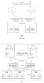
- FIG. 7 shows a situation where a storage node fails in the storage system shown in FIG. 1 .
- FIG. 8 shows an architectural schematic diagram of a particular storage system constructed according to an embodiment of the present invention.
- FIG. 9 shows an architectural schematic diagram of a storage system according to another embodiment of the present invention.
- FIG. 10 shows a flowchart of an access control method for an exemplary storage system according to an embodiment of the present invention.
- FIG. 11 shows an architectural schematic diagram to achieve load rebalancing in the storage system shown in FIG. 4 according to an embodiment of the present invention.
- FIG. 12 shows an architectural schematic diagram to achieve load rebalancing in the storage system shown in FIG. 4 according to another embodiment of the present invention.
- FIG. 13 shows an architectural schematic diagram of a situation where a storage node fails in the storage system shown in FIG. 4 according to an embodiment of the present invention.
- FIG. 14 shows a flowchart of an access control method for a storage system according to an embodiment of the present invention.
- FIG. 15 shows a block diagram of an access control apparatus of a storage system according to an embodiment of the present invention.
- FIG. 16 shows a block diagram of a load rebalancing apparatus for a storage system according to an embodiment of the present invention.
- FIG. 17 shows an architectural schematic diagram of data migration in the process of achieving load rebalancing between storage nodes in a conventional storage system based on a TCP/IP network.
- FIG. 18 is a schematic structural diagram of a storage pool using redundant storage according to an embodiment of the present invention.
- FIG. 19 is a schematic structural diagram of a storage pool using redundant storage according to another embodiment of the present invention.
- FIG. 2 shows an architectural schematic diagram of a storage system according to an embodiment of the present invention.
- the storage system includes a storage network; storage nodes connected to the storage network, wherein the storage node is a software module that provides a storage service, instead of a hardware server including storage mediums in the usual sense, the storage node in the description of the subsequent embodiments also refers to the same concept, and will not be described again; and storage devices also connected to the storage network.
- Each storage device includes at least one storage medium.
- a storage device commonly used by the inventor may include 45 storage mediums.
- the storage network is configured to enable each storage node to access any of the storage mediums without passing through other storage node.
- a storage management software is run by a storage node, the storage management software run by all storage nodes consist of a distributed storage management software.
- the storage network may be an SAS storage network or PCI/e storage network or Infiniband storage network or Omni-Path network, the storage network may comprise at least one SAS switch or PCI/e switch or Infiniband switch or Omni-Path switch; and each of the storage device may have SAS interface or PCI/e interface or Infiniband interface or Omni-Path interface.
- FIG. 3 shows an architectural schematic diagram of a storage system according to another embodiment of the present invention.
- each storage device includes at least one high performance storage medium and at least one persistent storage medium. All or a part of one or more high performance storage mediums of the at least one high performance storage medium constitutes a high cache area; when data is written by the storage node, the data is first written into the high cache area, and then the data in the high cache area is written into the persistent storage medium by the same or another storage node.
- the storage node records the location of the persistent storage medium into which the data should ultimately be written in the high cache area while writing data into the high cache area; and then the same or another storage node write the data in the high cache area into the persistent storage medium in accordance to the location of the persistent storage medium into which the data should ultimately be written. After the data in the high cache area is written into the persistent storage medium, the corresponding data is cleared from the high cache area in time to release more space for new data to be written.
- the location of the persistent storage medium into which each data should ultimately be written is not limited by the high performance storage medium in which the data is saved. For example, as shown in FIG. 3 , some data may be cached in the high performance storage medium of the storage device 1 , but the persistent storage medium into which the data should ultimately be written is located in the storage device 2 .
- the high cache area is divided into at least two cache units, each cache unit including one or more high performance storage mediums, or including part or all of one or more high performance storage mediums. And, the high performance storage mediums included in each cache unit are located in the same storage device or different storage devices.
- some cache unit may include two complete high performance storage mediums, a part of two high performance storage mediums, or a part of one high performance storage medium and one complete high performance storage medium.
- each cache unit may be constituted by all or a part of at least two high performance storage mediums of at least two storage devices in a redundant storage mode.
- each storage node is responsible for managing zero to multiple cache units. That is, some storage nodes may not be responsible for managing the cache unit at all, but are responsible for copying the data in the cache unit to the persistent storage medium.
- some storage nodes may not be responsible for managing the cache unit at all, but are responsible for copying the data in the cache unit to the persistent storage medium.
- there are 9 storage nodes wherein the storage nodes N 0 . 1 to 8 are responsible for writing data into its corresponding cache unit, and the storage node No. 9 is only used to write the data in the cache unit into the corresponding persistent storage medium (as described above, the address of the corresponding persistent storage medium is also recorded in the corresponding cache data).
- some storage nodes can release more burden to perform other operations.
- a storage node dedicated to writing the cache data into persistent storage mediums can also write the cache data into persistent storage mediums in idle time, which greatly improves the efficiency of cache data transfer.
- each storage node can only read and write cache units managed by itself. Since multiple storage nodes are prone to conflict with each other when writing into one high performance storage medium at the same time, but do not conflict with each other when reading, therefore, in another embodiment, each storage node can only make data to be cached be written into the cache unit managed by itself, but can read all the cache units managed by itself and other storage nodes, that is, writing operation of the storage node to the cache unit is local, and reading operation may be global.
- other or all of the storage nodes may be configured such that these storage nodes take over the cache units previously managed by the failed storage node.
- all the cache units managed by the failed storage node may be taken over by one of the other storage nodes, and may also be taken over by at least two of the other storage nodes, each of which takes over a part of the cache units managed by the failed storage node.
- the storage system provided by the embodiment of the present invention may further include a storage control node connected to the storage network, adapted for allocating cache units to storage nodes; or a storage allocation module set in the storage node, adapted for determining the cache units managed by the storage node.
- a cache unit list in which cache units managed by each storage node can be recorded maintained by the storage control node or the storage allocation module may also be changed correspondingly; that is, cache units managed by each storage node are modified by modifying the cache unit list in which cache units managed by each storage node can be recorded maintained by the storage control node or the storage allocation module.
- the size information of the data needs to be written, and these three types of information are collectively referred to as a cache data block.
- data written into the high cache area may be performed by the following manner.
- a head pointer and a tail pointer are respectively recorded in a fixed position of the cache unit first, and the head pointer and the tail pointer initially point to the beginning position of a blank area in the cache unit.
- the head pointer increases the total size of the written cache data block, to point to the next blank area.
- the cache data When the cache data is cleared, size of the current cache data block and location of the persistent storage medium into which the data should be written are read from the position pointed by the tail pointer, the cache data of the size is written into the persistent storage medium at the specified location, and the tail pointer increases the size of the cleared cache data block, to point to the next cache data block and release the space of the cleared cache data.
- the value of the head or tail pointer exceeds the available cached size, the pointer should be rewinded accordingly (that is, the available cached size is reduced to return to the front portion of the cache unit); the available cached size is that the size of the cache unit minus the size of the head pointer and the size of the tail pointer.
- the existing cache data is cleared until there is enough cache space for writing cache data; if the available cache of the entire cache unit is smaller than the size of the cache database that needs to be written, the data is directly written into the persistent storage medium without caching; when the cache data is cleared, if the tail pointer is equal to the head pointer, the cache data is empty, and currently there is no cache data that needs to be cleared.
- all the storage areas of the storage node are located in the global high cache area, but not located in the memory of the physical server where the storage node is located or any other storage medium.
- the cache data written into the global high cache area can be shared by all storage nodes.
- work of writing the cache data into the persistent storage medium may be completed by each storage node, or one or more fixed storage nodes that are specifically responsible for the work are selected according to requirements. Such an implementation manner may improve balance of the load between different storage nodes.
- the storage node is configured to write data to be cached into any one (or specified) high performance storage medium in the global cache pool, and the same or other storage nodes write the cache data that are written into the global cache pool into the specified persistent storage medium in the global cache pool one by one.
- an application runs on the server where the storage node is located, such as on the computing node, in order to reduce the frequency of the application access to the persistent storage medium, each storage node temporarily saves the data commonly used by the application on the high performance storage medium. In this way, the application can read and write data directly from the high performance storage medium at runtime, thereby improving the running speed and performance of the application.
- the cache area is usually integrated on each storage node of the cluster server, that is, reading and writing operations of the cache data are performed on each host of the cluster server.
- Each server temporarily puts the commonly used data in its own built-in cache area, and then transfers the data in the cache area to the persistent storage medium in the storage pool for permanent storage when the system is idle. Since the cache area has the characteristics that the storage content disappears after the power is turned off, if set in the server host, unpredictable risks may be brought to the storage system. Once any host in the cluster server fails, the cache data saved in this host will be lost, which will seriously affect the reliability and stability of the entire storage system.
- the high cache area formed by the high performance storage mediums is set in the global storage pool independently of each host of the cluster server. In this manner, if a storage node in the cluster server fails, the cache data written by the node into the high performance storage medium is also not lost, which greatly enhances the reliability and stability of the storage system.
- the storage system may further comprise at least two servers, each of the at least two servers may comprise one storage node and at least one computing node; the computing node may be able to access storage medium via storage node, storage network and storage device without TCP/IP protocol; and a computing node may be a virtual machine or a container.
- FIG. 4 shows an architectural schematic diagram of a particular storage system constructed according to an embodiment of the present invention.
- the storage network is shown as an SAS switch in FIG. 4 , but it should be understood that the storage network may also be an SAS collection, or other forms that will be discussed later.
- FIG. 4 schematically shows three storage nodes, namely a storage node S 1 , a storage node S 2 and a storage node S 3 , which are respectively and directly connected to an SAS switch.
- the storage system shown in FIG. 4 includes physical servers 31 , 32 , and 33 , which are respectively connected to storage devices through the storage network.
- the physical server 31 includes computing nodes C 11 , C 12 and a storage node S 1 that are located in the physical server 31
- the physical server 32 includes computing nodes C 21 , C 22 and a storage node S 2 that are located in the physical server 32
- the physical server 33 includes computing nodes C 31 , C 32 and a storage node S 3 that are located in the physical server 33 .
- the storage system shown in FIG. 4 includes storage devices 34 , 35 , and 36 .
- the storage device 34 includes a storage medium 1 , a storage medium 2 , and a storage medium 3 , which are located in the storage device 34
- the storage device 35 includes a storage medium 1 , a storage medium 2 , and a storage medium 3 , which are located in the storage device 35
- the storage device 36 includes a storage medium 1 , a storage medium 2 , and a storage medium 3 , which are located in the storage device 36 .
- the storage network may be an SAS storage network
- the SAS storage network may include at least one SAS switch
- the storage system further includes at least one computing node, each storage node corresponds to one or more of the at least one computing node, and each storage device includes at least one storage medium having an SAS interface.
- FIG. 5 shows an architectural schematic diagram of a conventional multi-path storage system provided by the prior art.
- the conventional multi-path storage system is composed of a server, a plurality of switches, a plurality of storage device controllers, and a storage device, wherein the storage device is composed of at least one storage medium.
- Different interfaces of the server are respectively connected to different switches, and different switches are connected to different storage device controllers.
- the server wants to access the storage medium in the storage device, the server first connects to a storage device controller through a switch, and then locates the specific storage medium through the storage device controller.
- the server can connect to another storage device controller through another switch, and then locate the storage medium through the other storage device controller, thereby implementing multi-path switching. Since the path in the conventional multi-path storage system is built based on the IP address, the server is actually connected to the IP address of different storage device controllers through a plurality of different paths.
- the multi-path switching can only be implemented to the level of the storage device controller, and the multi-path switching cannot be implemented between the storage device controller and the specific storage medium. Therefore, the conventional multi-path storage system can only cope with the network failure between the server and the storage device controller, and cannot cope with a single point of failure of the storage device controller itself.
- the storage medium in the storage device is connected to the storage device through its SAS interface, and the storage node and the storage device are also connected to the SAS storage network through their respective SAS interfaces, so that the storage node can directly access a particular storage medium based on the SAS address of the storage medium.
- the SAS storage network is configured to enable each storage node access all storage mediums without passing through other storage nodes directly, all storage mediums in the storage devices constitute a global storage pool, and each storage node can read any storage medium in the global storage pool through the SAS switch.
- multi-path switching is implemented between the storage nodes and the storage mediums.
- the storage network of the storage system based on the SAS switch has advantages of high performance, large bandwidth, a single device including a large number of disks and so on.
- HBA host bus adapter
- SAS interface on a server motherboard storage mediums provided by the SAS system can be easily accessed simultaneously by multiple connected servers.
- the SAS switch and the storage device are connected through an SAS cable, and the storage device and the storage medium are also connected by the SAS interface, for example, the SAS channel in the storage device is connected to each storage medium (an SAS switch chip may be set up inside the storage device), the SAS storage network can be directly connected to the storage mediums, which has unique advantages over existing multi-paths built on a FC network or Ethernet.
- the bandwidth of the SAS network can reach 24 Gb or 48 Gb, which is dozens of times the bandwidth of the Gigabit Ethernet, and several times the bandwidth of the expensive 10-Gigabit Ethernet; at the link layer, the SAS network has about an order of magnitude improvement over the IP network, and at the transport layer, a TCP connection is established with a three handshake and closed with a four handshake, so the overhead is high, and Delayed Acknowledgement mechanism and Slow Start mechanism of the TCP protocol may cause a 100-millisecond-level delay, while the delay caused by the SAS protocol is only a few tenths of that of the TCP protocol, so there is a greater improvement in performance.
- the SAS network offers significant advantages in terms of bandwidth and delay over the Ethernet-based TCP/IP network. Those skilled in the art can understand that the performance of the PCI/e channel can also be adapted to meet the needs of the system.
- each computing node can be connected to each storage medium of the at least one storage device through any storage node.
- multi-path access by the same computing node through different storage nodes is implemented.
- Each storage node in the formed storage system architecture has a standby node, which can effectively cope with a single point of failure of the storage node, and the path switching process may be completed immediately after the single point of failure, and there is no switching takeover time for the failure tolerance.
- an embodiment of the present invention further provides an access control method for the storage system, including: when any one of the storage nodes fails, making a computing node connected to the failure storage node read and write storage mediums through other storage nodes.
- the computing node connected to the failed storage node may implement multi-path access through other storage nodes.
- the physical server where each storage node is located has at least one SAS interface, and the at least one SAS interface of the physical server where each storage node is located is respectively connected to at least one SAS switch; each storage device has at least one SAS interface, the at least one SAS interface of each storage device is respectively connected to at least one SAS switch.
- each storage node can access the storage medium through at least one SAS path.
- the SAS path is composed of any SAS interface of the physical server where the storage node currently performing access is located, an SAS switch corresponding to the any SAS interface, an SAS interface of the storage device to be accessed, and an SAS interface of the storage medium to be accessed.
- the same computing node may access the storage medium through at least one SAS path of the same storage node, in addition to multi-path access through different storage nodes.
- the computing node may implement multi-path access through multiple SAS paths of the storage node. Therefore, in summary, each computing node may access the storage medium through at least two access paths, wherein at least two access paths include different SAS paths of the same storage node, or any SAS path of each of different storage nodes.
- FIG. 6 shows an architectural schematic diagram of a storage system according to another embodiment of the present invention.
- the storage system includes at least two SAS switches; the physical server where each storage node is located has at least two SAS interfaces, and the at least two SAS interfaces of the physical server where each storage node is located are respectively connected to at least two SAS switches; each storage device has at least two SAS interfaces, and the at least two SAS interfaces of each storage device are respectively connected to the at least two SAS switches.
- each of the at least two storage nodes may access the storage medium through at least two SAS paths, each of the at least two SAS paths corresponds to a different SAS interface of the physical server where the storage node is located, and the different SAS interface corresponds to a different SAS switch. And, since each storage device has at least two SAS interfaces, the storage medium in each storage device is constant, therefore, different SAS interfaces of the same storage device are connected to the same storage medium through different lines.
- any one of the storage node and the SAS switch has a standby node for switching when a single point of failure, which can effectively cope with a single point of failure for any node in any access path. Therefore, based on the storage system structure as shown in FIG. 6 , on the access path of the computing node accessing the storage medium, any one of the storage node and the SAS switch has a standby node for switching when a single point of failure, which can effectively cope with a single point of failure for any node in any access path. Therefore, based on the storage system structure as shown in FIG.
- an embodiment of the present invention further provides an access control method for the storage system, including: when any one of the SAS paths fails, making the storage node connected to the failed SAS path read and write the storage medium by the other SAS path, wherein the SAS path is composed of any SAS interface of the physical server where the storage node currently performing access is located, an SAS switch corresponding to the any SAS interface, an SAS interface of the storage device to be accessed, and an SAS interface of the storage medium to be accessed.
- the SAS storage network includes multiple SAS switches
- different storage nodes may still perform multi-path access to the storage medium based on the same SAS switch, that is, when any one storage node fails, the computing node connected to the failed storage node may read and write the storage medium through other storage nodes but based on the same SAS switch.
- each storage medium in the SAS storage network has an SAS address
- the SAS address of the storage device to be connected in the SAS storage network may be used to locate the location of the storage medium to be connected.
- the SAS address may be a globally unique WWN (World Wide Name) code.
- the storage node is located in the storage-medium-side, or strictly speaking, the storage medium is a built-in disk of a physical device where the storage node is located.
- the physical device where the storage node is located is independent of the storage device, and each storage node and one computing node are set in the same physical server, and the physical server is connected to the storage device through the SAS storage network.
- the storage node may directly access the storage medium through the SAS storage network, so the storage device is mainly used as a channel to connect the storage medium and the storage network.
- the number of physical devices required can be reduced from the point of view of whole system, and thereby the cost is reduced.
- the computing node can locally access any storage resource that they want to access.
- data exchanging between the two can be as simple as memory sharing or API call, so the performance is particularly excellent.
- each storage node and its corresponding computing node are both located in the same server, and the physical server is connected to the storage device through the storage switching device.
- each storage node accesses at least two storage devices through a storage network, and data is saved in a redundant storage mode between at least one storage block of each of the at least two storage devices accessed by the same storage node, wherein the storage block is one complete storage medium or a part of one storage medium. It can be seen that since the data is saved in the storage blocks of different storage devices in a redundant storage mode, and thus the storage system is a redundant storage system.
- the storage node is located in the storage-medium-side, the storage medium is a built-in disk of a physical device where the storage node is located, the storage node is equivalent to a control machine of all storage mediums in the local physical device, the storage node and all the storage mediums in the local physical device constitute a storage device.
- disaster recovery processing can be implemented by means of redundant storage between the disks mounted on each storage node S, when a storage node S fails, the disks mounted under the storage node may no longer be read or written, and restoring the data in the disks mounted by the failed storage node S may seriously affect the working efficiency of the entire redundant storage system.
- the physical device where the storage node is located is independent of the storage device
- the storage device is mainly used as a channel to connect the storage medium and the storage network
- the storage node and the storage device are respectively connected to the storage network independently
- each storage node may access multiple storage devices through the storage network
- the multiple storage devices accessed by the same storage node are redundantly saved, and thus this enables redundant storage across storage devices under the same storage node.
- the data in the storage device may be quickly resaved through other normal working storage devices, which greatly improves the disaster recovery processing efficiency of the entire storage system.
- each storage node may access all the storage mediums without passing through other storage node, so that all the storage mediums are actually shared by all the storage nodes, and therefore a global storage pool is achieved.
- the storage network is configured to make each of the storage node only be responsible for managing a fixed storage medium at the same time, and ensure that one storage medium is not written by multiple storage nodes at the same time, which may result in data corruption, and thereby it may be implemented that each storage node may access to the storage mediums managed by itself without passing through other storage nodes, and the integrity of the data saved in the storage system may be guaranteed.
- the constructed storage pool may be divided into at least two storage areas, and each storage node is responsible for managing zero to multiple storage areas. Referring to FIG.
- the storage node S 1 is responsible for managing the first storage area, which includes the storage medium 1 in the storage device 34 , the storage medium 1 in the storage device 35 , and the storage medium 1 in the storage device 36 ;
- the storage node S 2 is responsible for managing the second storage area, which includes a storage medium 2 in the storage device 34 , a storage medium 2 in the storage device 35 , and a storage medium 2 in the storage device 36 ;
- the storage node S 3 is responsible for managing the third storage area, which includes the storage medium 3 in the storage device 34 , the storage medium 3 in the storage device 35 , and the storage medium 3 in the storage device 36 .
- the storage medium is a built-in disk of a physical device where the storage node is located; in the embodiments of the present invention, the physical device where the storage node is located, is independent of the storage device, and the storage device is mainly used as a channel to connect the storage medium to the storage network.
- FIG. 7 shows a situation where a storage node fails in the storage system shown in FIG. 1 , in which the disks mounted under the failed storage node may not be accessed.
- the computing node C may no longer be able to access the data in the disks mounted and managed by the failed storage node.
- the storage areas managed by the failed storage node may not become invalid storage areas in the storage system, may still be accessed by other storage nodes, and administrative rights of the storage areas may be allocated to other storage nodes.
- the storage-node-side further includes a computing node, and the computing node and the storage node are located in same physical server connected with the storage devices via the storage network.
- the I/O (input/output) data path between the computing node and the storage medium includes: (1) the path from the storage medium to the storage node via storage device and storage network; and (2) the path from the storage node to the computing node located in one same physical server.
- the full data path doesn't use TCP/IP protocol.
- the I/O data path between the computing node and the storage medium includes: (1) the path from the storage medium to the storage node; (2) the path from the storage node to the access network switch of the storage network; (3) the path from the access network switch of the storage network to the kernel network switch; (4) the path from the kernel network switch to the access network switch of the computing network; and (5) the path from the access network switch of the computing network to the computing node.
- each computing node since the physical server where each computing node is located has a storage node, there is a network connection between the physical servers, therefore, the computing node in a physical server may also access the storage mediums through the storage node in another physical server. In this way, the same computing node may multi-path access the storage mediums through different storage nodes.
- the storage node may be a virtual machine of a physical server, a container or a module running directly on a physical operating system of the server, or the combination of the above (For example, a part of the storage node is a firmware on an expansion card, another part is a module of a physical operating system, and another part is in a virtual machine), and the computing node may also be a virtual machine of the same physical server, a container, or a module running directly on a physical operating system of the server.
- each storage node may correspond to one or more computing nodes.
- one physical server may be divided into multiple virtual machines, wherein one of the virtual machines may be used as the storage node, and the other virtual machines may be used as the computing nodes; or, in order to achieve a better performance, one module on the physical OS (operating system) may be used as the storage node.
- one module on the physical OS operating system
- the virtual machine may be built through one of following virtualization technologies: KVM, Zen, VMware and Hyper-V
- the container may be built through one of following container technologies: Docker, Rockett, Odin, Chef, LXC, Vagrant, Ansible, Zone, Jail and Hyper-V.
- the storage nodes are only responsible for managing corresponding storage mediums respectively at the same time, and one storage medium cannot be simultaneously written by multiple storage nodes, so that data conflicts can be avoided.
- each storage node can access the storage mediums managed by itself without passing through other storage nodes, and integrity of the data saved in the storage system can be ensured.
- all the storage mediums in the system may be divided according to a storage logic.
- the storage pool of the entire system may be divided according to a logical storage hierarchy which includes storage areas, storage groups and storage blocks, wherein, the storage block is the smallest storage unit.
- the storage pool may be divided into at least two storage areas.
- each storage area may be divided into at least one storage group. In a preferred embodiment, each storage area is divided into at least two storage groups.
- the storage areas and the storage groups may be merged, so that one level may be omitted in the logical storage hierarchy.
- each storage area may include at least one storage block, wherein the storage block may be one complete storage medium or a part of one storage medium.
- each storage area may include at least two storage blocks, when any one of the storage blocks fails, complete data saved can be calculated from the rest of the storage blocks in the storage area.
- the redundant storage mode may be a multi-copy mode, a redundant array of independent disks (RAID) mode, or an erasure code mode, or BCH (Bose-Chaudhuri-Hocquenghem) codes mode, or RC (Reed-Solomon) codes mode, or LDPC (low-density parity-check) codes mode, or a mode that adopts other error-correcting code.
- the redundant storage mode may be built through a ZFS (zettabyte file system).
- the storage blocks included in each storage area (or storage group) may not be located in one same storage medium, even not be located in one same storage device.
- any two storage blocks included in same storage area may not be located in one same storage medium, or even not located in one same storage device.
- the number of the storage blocks located in same storage medium/storage device is preferably less than or equal to the fault tolerance level (the max number of failed storage blocks without losing data) of the redundant storage.
- the fault tolerance level is 1, so in one storage area (or storage group), the number of the storage blocks located in same storage medium/storage device is at most 1; for RAID6, the fault tolerance level of the redundant storage mode is 2, so in one storage area (or storage group), the number of the storage blocks located in same storage medium/storage device is at most 2.
- the storage system further includes a fault tolerance level adjustment module, adjusting the fault tolerance level of the storage pool by adjusting the redundant storage mode of a storage group and/or adjusting the maximum number of storage blocks that belong to same storage group and located in same storage devices of the storage pool.
- each storage node can only read and write the storage areas managed by itself.
- each storage node since multiple storage nodes do not conflict with each other when read one same storage block but easily conflict with each other when writing one same storage block, each storage node can only write the storage areas managed by itself but can read the storage areas managed by itself and the storage areas managed by the other storage nodes. Thus it can be seen that writing operations are local, but reading operations are global.
- the storage system may further include a storage control node, which is connected to the storage network and adapted for allocating storage areas to the at least two storage nodes.
- each storage node may include a storage allocation module, adapted for determining the storage areas managed by the storage node. The determining operation may be implemented through communication and coordination algorithms between the storage allocation modules included in each storage node, for example, the algorithms may be based on a principle of load balancing between the storage nodes.
- some or all of the other storage nodes may be configured to take over the storage areas previously managed by the failed storage node.
- one of the other storage nodes may be configured to take over the storage areas previously managed by the failed storage node, or at least two of the other storage nodes may be configured to take over the storage areas previously managed by the failed storage node, wherein each storage node may be configured to take over a part of the storage areas previously managed by the failed storage node, for example the at least two of the other storage nodes may be configured to respectively take over different storage groups of the storage areas previously managed by the failed storage node.
- the takeover of the storage areas by the storage node is also described as migrating the storage areas to the storage node herein.
- the storage medium may include but is not limited to a hard disk, a flash storage, a SRAM (static random access memory), a DRAM (dynamic random access memory), a NVME (non-volatile memory express) storage, a 3DXPoint storage, a NVRAM (Nonvolatile Random Access Memory) storage, or the like
- an access interface of the storage medium may include but is not limited to an SAS (serial attached SCSI) interface, a SATA (serial advanced technology attachment) interface, a PCI/e (peripheral component interface-express) interface, a DIMM (dual in-line memory module) interface, a NVMe (non-volatile memory express) interface, a SCSI (small computer systems interface), an ethernet interface, an infiniband interface, a omipath interface, or an AHCI (advanced host controller interface).
- SAS serial attached SCSI
- SATA serial advanced technology attachment
- PCI/e peripheral component interface-express
- the storage medium may be a high performance storage medium or a persistent storage medium herein.
- the storage network may include at least one storage switching device, and the storage nodes access the storage mediums through data exchanging between the storage switching devices. Specifically, the storage nodes and the storage mediums are respectively connected to the storage switching device through a storage channel.
- a storage system supporting multi-nodes control is provided, and a single storage space of the storage system can be accessed through multiple channels, such as by a computing node.
- the storage switching device may be an SAS switch, an ethernet switch, an infiniband switch, an omnipath switch or a PCI/e switch, and correspondingly the storage channel may be an SAS (Serial Attached SCSI) channel, an ethernet channel, an infiniband channel, an omnipath channel or a PCI/e channel.
- SAS Serial Attached SCSI
- the storage network may include at least two storage switching devices, each of the storage nodes may be connected to any storage device through any storage switching device, and further connected with the storage mediums.
- a storage switching device or a storage channel connected to a storage switching device fails, the storage nodes can read and write the data in the storage devices through the other storage switching devices, which enhances the reliability of data transfer in the storage system.
- FIG. 8 shows an architectural schematic diagram of a particular storage system constructed according to an embodiment of the present invention.
- a specific storage system 30 provided by an embodiment of the present invention is illustrated.
- the storage devices in the storage system 30 are constructed as multiple JBODs (Just a Bunch of Disks) 307 - 310 , these JBODs are respectively connected with two SAS switches 305 and 306 via an SAS cables, and the two SAS switches constitute the switching core of the storage network included in the storage system.
- a front end includes at least two servers 301 and 302 , and each of the servers is connected with the two SAS switches 305 and 306 through a HBA device (not shown) or an SAS interface on the motherboard. There is a basic network connection between the servers for monitoring and communication.
- Each of the servers has a storage node that manages some or all of the disks in all the JBODs.
- the disks in the JBODs may be divided into different storage groups according to the storage areas, the storage groups, and the storage blocks described above.
- Each of the storage nodes manages one or more storage groups. When each of the storage groups applies the redundant storage mode, redundant storage metadata may be saved on the disks, so that the redundant storage mode may be directly identified from the disks by the other storage nodes.
- FIG. 9 shows an architectural schematic diagram of a storage system according to another embodiment of the present invention.
- the storage device in the storage system 30 is constructed into a plurality of JBODs 307 - 310 , which are respectively connected to two SAS switches 305 and 306 through a SAS data line, the two SAS switches constitute kernel switches of the SAS storage network included in the storage system, and front end includes at least two servers 301 and 302 .
- the server 301 includes at least two adapters 301 a and 301 b , and the at least two adapters 301 a and 301 b are respectively connected to at least two SAS switches 305 and 306 ;
- the server 302 includes at least two adapters 302 a and 302 b , and the at least two adapters 302 a and 302 b are respectively connected to at least two SAS switches 305 and 306 .
- the access control method provided by an embodiment of the present invention may further include: when any adapter of a storage node fails, the storage node is connected to the corresponding SAS switch through another adapter.
- the server 302 may not be connected to the SAS switch 305 through the adapter 302 a , and the server 302 may still be connected to the SAS switch 306 through the adapter 302 b.
- Each server has a storage node that manages some or all of the disks in all JBOD disks by using information obtained from the SAS links.
- the disks in the JBODs may be divided into different storage groups according to the storage areas, the storage groups, and the storage blocks described above.
- Each of the storage nodes manage one or more storage groups.
- redundant storage metadata may be saved on the disks, so that the redundant storage mode may be directly identified from the disks by the other storage nodes.
- a monitoring and management module may be installed in the storage node to be responsible for monitoring status of local storage and the other server.
- a JBOD is overall abnormal or a certain disk on a JBOD is abnormal, data reliability is ensured by the redundant storage mode.
- the monitoring and management module in the storage node of another pre-set server will identify locally and take over the disks previously managed by the storage node of the failed server, according to the data in the disks.
- the storage services previously provided by the storage node of the failed server will also be continued on the storage node of the new server. At this point, a new global storage pool structure with high availability is achieved.
- the exemplary storage system 30 provides a storage pool that supports multi-nodes control and global access.
- multiple servers are used to provide the services for external user, and the JBODs are used to accommodate the disks.
- Each of the JBODs is respectively connected to two SAS switches, and the two switches are respectively connected to a HBA card of the servers, thereby ensuring that all the disks on the JBODs can be accessed by all the servers.
- SAS redundant links also ensure high availability on the links.
- each server On the local side of each server, according to the redundant storage technology, disks are selected from each JBOD to form the redundant storage mode, to avoid the data unable to be accessed due to the failure of one JBOD.
- the module that monitors the overall state may schedule another server to access the disks managed by the storage node of the failed server through the SAS channels, to quickly take over the disks previously managed by the failed server and achieve the global storage pool with high availability.
- the JBODs may be used to accommodate the disks
- the embodiment of the present invention shown in FIG. 8 also may apply other storage devices than the JBODs.
- the above description is based on the case that one (entire) storage medium is used as one storage block, but also applies to the case that a part of one storage medium is used as one storage block.
- An embodiment of the present invention further provides an access control apparatus for a storage system, wherein the storage system applied includes: an SAS storage network, including at least one SAS switch; at least two storage nodes, which are connected to the SAS storage network; at least one storage device, which is connected to the SAS storage network; and at least one computing node, each storage node corresponding to one or more computing nodes of the at least one computing node, wherein, each storage device includes at least one storage medium with an SAS interface, the SAS storage network being configured to enable each storage node directly access to all the storage mediums without passing through other storage nodes; the apparatus includes: an access path switching module, adapted for when any one of the storage nodes fails, making a computing node connected to the failure storage node read and write storage mediums through other storage nodes.
- an access path switching module adapted for when any one of the storage nodes fails, making a computing node connected to the failure storage node read and write storage mediums through other storage nodes.
- the SAS storage network includes at least two SAS switches; the physical server where each storage node is located has at least two SAS interfaces, and the at least two SAS interfaces of the physical server where each storage node is located are respectively connected to at least two SAS switches; each storage device has at least two SAS interfaces, and the at least two SAS interfaces of each storage device are respectively connected to the at least two SAS switches; the access path switching module can also be adapted for when any one of the SAS paths fails, making the storage node connected to the failed SAS path read and write the storage medium by the other SAS path; wherein the SAS path is composed of any SAS interface of the physical server where the storage node currently performing access is located, an SAS switch corresponding to the any SAS interface, an SAS interface of the storage device to be accessed, and an SAS interface of the storage medium to be accessed.
- FIG. 10 shows a flowchart of an access control method 41 for an exemplary storage system according to an embodiment of the present invention.
- step S 401 monitoring a load status between at least two storage nodes included in the storage system.
- step S 402 when it is detected that load of one storage node exceeds a predetermined threshold, the storage area managed by the relevant storage node of the at least two storage nodes is adjusted.
- the relevant storage node may be a storage node that causes an unbalanced state of the load, and may be determined depending on an adjustment policy of the storage area.
- the adjustment of the storage area may be that the storage blocks involved are reallocated between the storage nodes, or may be addition, merging, or deletion of the storage areas.
- the configuration table of the storage area managed by the relevant storage node may be adjusted, and the at least two storage nodes determine the storage area they manage according to the configuration table.
- the adjustment of the foregoing configuration table may be performed by a storage control node included in the foregoing storage system or a storage allocation module included in the storage node.
- monitoring a load status between the at least two storage nodes may be performed for one or more of the following performance parameters: the number of reading and writing operations per second (IOPS) of the storage node, the throughput of the storage node, CPU usage of the storage node, memory usage of the storage node, and the storage space usage of the storage area managed by the storage node.
- IOPS reading and writing operations per second
- each node may periodically monitor its own performance parameters, periodically query data of other nodes at the same time, then dynamically generate a globally unified rebalancing scheme through a predefined rebalancing scheme or through an algorithm, and finally implement the scheme by each node.
- the storage system includes a monitoring node that is independent of the storage node S 1 , the storage node S 2 , and the storage node S 3 , the foregoing storage control node or the storage allocation module, in order to monitor performance parameters of each storage node.
- the determination of the unbalanced may be achieved by a predefined threshold (configurable), such as triggering a rebalancing mechanism when the deviation of the number of IOPS between the respective nodes exceeds a certain range.
- a predefined threshold configurable
- the IOPS value of the storage node with the maximum IOPS value may be compared with the IOPS value of the storage node with the minimum IOPS value, when it is determined that the deviation between the two is greater than 30% of the latter, the storage area adjustment is triggered.
- a storage medium managed by the storage node with the maximum IOPS value is exchanged with a storage medium managed by a storage node with the minimum IOPS value, for example, a storage node with the maximum IOPS which manages the storage area with the highest storage space usage may be chosen, and a storage node with the minimum IOPS which manages the storage area with the highest storage space usage may be chosen.
- the IOPS value of the storage node with the maximum IOPS value may be compared with the average value of the IOPS value of each storage node, and when it is determined that the deviation between the two is greater than 20% of the latter, the storage area adjustment is triggered, so that the storage area allocation scheme which has been adjusted may not trigger rebalancing immediately.
- predetermined thresholds 20% or 30% for representing the unbalanced state of the load are merely exemplary, and additional thresholds may be defined depending on different applications and different requirements.
- additional thresholds may be defined depending on different applications and different requirements.
- a predefined definition is also used to trigger the threshold for the load to be rebalanced between the storage nodes.
- the predetermined threshold for the unbalanced determination discussed above may by determined by one of respective specified thresholds of a plurality of the performance parameters, such as IOPS value
- the predetermined threshold may be determined by a combination of multiple specified thresholds of the respective specified thresholds of a plurality of the performance parameters. For example, load rebalancing of a storage node is triggered when the IOPS value of the storage node reaches its specified threshold and the throughput value of the storage node reaches its specified threshold.
- the storage mediums managed by the storage node with high load may be allocated to the storage areas managed by the storage node with low load, for example, exchanging of storage mediums, deleting in the storage areas managed by a storage node with a high load and adding in the storage areas managed by a storage node with a low load, evenly adding a new storage medium or a new storage area accessed to the storage network to at least two storage areas (for example, storage system expansion), or merging a part of at least two storage areas (for example, a storage node failure) may be included.
- a dynamic algorithm for the adjustment (rebalancing) of the storage areas, a dynamic algorithm may be developed, for example, various load data of each storage medium and each storage node is weighted to obtain a single load indicator, and then a rebalancing solution is calculated, by moving the minimum number of disk groups, so that the system no longer exceeds the predetermined threshold.
- each storage node may periodically monitor the performance parameters of the storage medium managed by itself, and periodically query the performance parameters of the storage medium managed by other storage nodes, and a threshold for indicating the unbalanced state of the load for performance parameters of the storage medium is defined, for example, the threshold may represent the storage space usage rate of any storage medium (a new disk adds) is 0%, the storage space usage rate of any storage medium (the disk space will be full) is 90%, or the difference of the storage medium with the highest storage space usage rate in the storage system and the storage medium with the lowest storage space usage rate is greater than 20% of the latter. It should be understood that the aforementioned predetermined thresholds 0%, 90% and 30% for indicating the unbalanced state of the load are also merely exemplary.
- FIG. 11 shows an architectural schematic diagram to achieve load rebalancing in the storage system shown in FIG. 4 according to an embodiment of the present invention.
- the storage mediums managed by the storage node S 1 include a storage medium 1 located at the storage device 34 , a storage medium 1 located at the storage device 35 , and a storage medium 1 located at the storage device 36 (as shown in FIG. 4 ), and the total storage space of the storage node S 1 will soon be used up, and the load of the storage node 3 is very low, and the storage space in the storage medium managed by the storage node 3 is large.
- each storage node may only access the storage areas that are directly connected to itself. Therefore, during the rebalancing process, the data in a heavy-load storage node needs to be copied to a light-load storage node. In this process, there are a large number of data copy operations, which will cause additional load to the storage area and the network, affecting IO access of normal business data. For example, data in one or more storage mediums managed by the storage node 1 are read, then the data is written into one or more storage mediums managed by the storage node 3 , and finally the disk space for saving the data in the storage mediums managed by the storage node 1 is released, so that the load balancing is achieved.
- the storage nodes S 1 , S 2 , and S 3 included in the storage system may access all the storage areas through the storage network, and therefore, the migration of storage areas between storage nodes may be achieved by the means of moving the access right of storage medium, that is, the storage areas managed by a relevant storage node may be regrouped. During the rebalancing process, the data in each storage area no longer need to be copied. For example, as shown in FIG.
- the storage medium 2 which is previously managed by the storage node 3 and located at the storage device 34 , is allocated to the storage node 1 for management, and the storage medium 1 , which is previously managed by the storage node 1 and located at the storage device 34 , is allocated to the storage node 3 for management, in this way, the load balancing of the remaining storage space between the storage node 1 and the storage node 3 is achieved.
- FIG. 12 shows an architectural schematic diagram to achieve load rebalancing in the storage system shown in FIG. 4 according to another embodiment of the present invention.
- the storage medium 2 which is previously managed by the storage node 2 and located at the storage device 35 may be allocated to the storage node 1 for management, and the storage medium 1 which is previously managed by the storage node 1 and located at the storage device 34 may be allocated to the storage node 2 for management, in this way, the load balancing of the remaining storage space between the storage node 1 and the storage node 2 is achieved.
- the newly added storage mediums can be allocated equally to each storage node and managed by it, such as by the added order, to maintain the load rebalancing between the storage nodes.
- the above two embodiments take an example of achieving load rebalancing by adjusting storage mediums between different storage nodes
- the above two embodiments may also be applied to adjusting storage areas between storage nodes to achieve load rebalancing, for example, in the case of the storage medium expansion, when it is detected that storage areas are added, the added storage areas may be allocated to each storage node in addition order.
- the configuration between computing nodes and storage nodes in the storage system may also be modified, so that one or more computing nodes, such as the computing node C 12 , that originally save data through the storage node S 1 , may save data through another storage node, such as the storage node S 2 .
- a computing node may access a storage node on the physical server where the computing node is located to save data, the computing node may not be physically migrated, and access the storage areas on the remote storage node through remote access protocols, such as iSCSI protocol (as shown in FIG. 11 ); or, a computing node may be migrated (as shown in FIG. 12 ) while the storage areas managed by the relevant storage node is adjusted, and the computing node that is to be migrated may need to be closed in the process.
- a storage system may include at least two storage nodes, a storage network, and at least one storage device connected to the at least two storage nodes through the storage network, each of the storage devices can include at least one storage medium, and the storage network can be configured to enable each storage node to access all the storage medium without passing through the other storage nodes.
- FIG. 13 shows an architectural schematic diagram of a situation where a storage node fails in the storage system shown in FIG. 4 according to an embodiment of the present invention.
- FIG. 13 shows the case that the storage node S 3 fails.
- the storage mediums previously managed by the storage node S 3 may be taken over by the other storage nodes.
- FIG. 13 using different background patterns schematically shows the case that the storage mediums previously managed by the storage node S 3 are taken over by the storage node S 1 and the storage node S 2 . That is, the storage medium 3 included in the storage device 34 and the storage device 36 is taken over by the storage node S 1 , and the storage medium 3 included in the storage device 35 is taken over by the storage node S 2 .
- the computing node C can access data in the various storage mediums included in the storage devices 34 , 35 , and 36 through the remaining two storage nodes, namely the storage node S 1 and the storage node S 2 .
- a storage system may include at least two storage nodes, a storage network and at least one storage device connected to the at least two storage nodes through the storage network, each of the storage devices can include at least one storage medium, and the storage network can be configured to enable each storage node to access all the storage mediums without passing through the other storage nodes.
- FIG. 14 shows a flowchart of an access control method for a storage system according to an embodiment of the present invention.
- Step 501 detecting whether there is one or more storage node in the at least two storage nodes fails.
- the reachability of each storage node can be detected in real time.
- Step 502 when a failed storage node is detected, at least one of the other storage nodes of the at least two storage nodes can be configured to take over the storage areas previously managed by the failed storage node.
- a storage area list in which storage areas managed by each storage node can be recorded, and the storage area list can be modified to make the relevant storage node take over the storage areas previously managed by the failed storage node. For example, adjustment may be done by modifying the configuration table of the storage areas, and the storage areas managed by each storage node of the at least two storage nodes can be determined according to the configuration table. The adjustment of the configuration table can be performed by the storage control node included in the storage system or by the storage allocation module included in the storage node.
- heartbeat can be detected to judge whether there is a failed storage node in the at least two storage nodes.
- the heartbeat between each server can be detected to judge whether the other side fails.
- the heartbeat detection can be achieved in many ways. In an embodiment, for example, the heartbeat detection can be achieved through a TCP connection, where the detect-side sends a data package first, the receive-side automatically replies a data package, and if the detect-side does not receive the response of the receive-side for a long time, the receive-side can be judged to have failed.
- the heartbeat detection can be achieved by means of an arbitration block, where both sides write data into different areas of the arbitration block at regular intervals, and read the data written by the other side at regular intervals. If the other side is found to have not written new data for a long time, the other side is judged to have failed. Further, it may be necessary to solve the case of misjudgment, that is, the other side has not failed, and only the heartbeat between the both sides has a problem, for example, the network between the both sides is disconnected. A variety of independent heartbeats are often used to make a comprehensive judgment. For example, the above TCP connection and the arbitration block are used at the same time, and only when both heartbeats determine that the other side has failed, it is considered a true failure.
- each storage area is managed by one of the storage nodes.
- the storage node When a storage node is started, the storage node automatically connects to the storage areas managed by itself, and then import is made, after that is completed, storage services may be provided to the upper computing nodes.
- the storage areas needed to be migrated can be determined by many ways of implementation.
- the storage areas needed to be migrated can be manually judged by the manager.
- configuration files can be used, that is, the migration priority of each storage area should be configured in advance, and when the migration is needed, one or more storage blocks, storage groups, or storage mediums in the storage areas managed by the storage node which are in the highest priority are selected to be migrated.
- the migration can be performed according to the load of a storage block, a storage group or a storage medium included in a storage area.
- the load of a storage block, a storage group or a storage medium included in the storage area managed by each storage node can be monitored by each storage node, for example, the information such as IOPS, throughput, IO latency, and so on can be collected, and all the information can be weighted together, so that the storage areas needed to be migrated can be selected.
- the storage nodes to which the storage areas migrate can be determined by many ways of implementation.
- the storage nodes can be manually judged by the manager.
- configuration files can be used, that is, a migration target list of each storage area should be configured in advance, such as a list in which the storage nodes may be arranged according to the priority of the storage node, and when a storage area (or part) is needed to be migrated, the migration destinations can be selected in turn according to the list. It should be noted that, when the storage nodes are determined by this way, the target storage node is not overloaded after migration that should be ensured.
- the storage nodes to which the storage areas migrate can be determined by many ways of implementation.
- the storage nodes to which the storage areas migrate may be manually judged by the manager.
- configuration files can be used, that is, a migration target list of each storage area should be configured in advance, such as a list in which the storages nodes may be arranged according to the priority of the storage node, and when it is determined that a storage area (or part) is needed to be migrated, the migration destinations can be selected in turn according to the list.
- a hot standby storage node can be set up, and none storage area is managed by the hot standby storage node normally, that is, the hot standby storage node is not loaded. Once any storage node fails, the storage areas managed previously by the failed storage node can be migrated to the hot standby storage node.
- a storage node to be migrated can be selected according to the load of each storage node, and the load of each storage node can be monitored, for example, the information such as CPU usage rate, memory usage rate, network bandwidth usage rate, and so on can be collected, and all the information can be weighted together, so that the storage areas needed to be migrated can be selected.
- the load of each node can be reported by each storage node itself to the other storage nodes periodically or irregularly, and when migration is needed, a storage node with the lowest load can be selected by the storage node in which data needs to migrate as the target storage node for migration.
- the storage areas taken over by other storage nodes need to migrate back, and under this case, the storage areas which are needed to migrate and the target storage node are known (for example, each migration process can be recorded in the above configuration files), and there is only need to resave the storage areas originally managed by the failed storage node.
- the migration process can be determined and started by the storage system administrator, or it can be started by a program.
- the specific migration process namely the takeover process
- the storage areas need to be initialized by the target storage node, to repair the inconsistent data (if it exists), and finally the upper application should be notified to access the storage areas taken over by the target storage node through the target storage node.
- the storage system administrator can determine and start the specific migration process, or the migration process can be started by a program.
- the impact caused by the migration process to the upper computing nodes needs to be reduced, for example, the time that the application load is minimal can be selected to perform the migration process, or the migration operation is performed at midnight (assuming load is minimal at this time); when the computing node needs to be closed during the migration process, it should be done as far as possible when the utilization of the computing node is low.
- the migration strategy should be configured previously, so that when many storage areas or many parts of a storage area need to be migrated, migration order and concurrent quantity can be controlled.
- the writing or reading operations of the relevant storage area corresponding to the relevant storage node can be configured, so that the integrity of the data can be ensured, for example, all cache data can be written into disks; after the storage area migrates to the target storage node, the storage area needs to be initialized by the target storage node, and then the storage area can be accessed by the upper computing node; after the migration process is completed, the load status should be monitored again to determine whether the load is balancing.
- the storage node without storage areas managed currently by itself can be selected to take over the storage areas managed by the failed storage node.
- the storage areas to be taken over by each takeover storage node can be distributed follow the principle of equal distribution, or the storage areas to be taken over by each takeover storage node can be distributed according to the level of the load.
- part or all of the other storage nodes of the at least two storage nodes may be configured, so that the storage areas previously managed by the failed storage node may be taken over by them.
- storage areas managed by the failed storage node may be taken over by one of the other storage nodes, or by at least two storage nodes of the other storage nodes, wherein a part of the storage areas managed by the failed storage node can be taken over by each storage node.
- the system may include a storage control node, connected to the network, adapted for allocating storage areas to the at least two storage nodes; or, the storage node may also include a storage allocation module, adapted for determining the storage areas managed by the storage node, and data can be shared between the storage allocation modules.
- a storage control node or a storage allocation module records a storage area list in which storage areas for which each storage node is responsible can be recorded. After the storage node starts up, it queries the storage control node or the storage allocation module for the storage areas managed by itself, and then scans these storage areas to complete the initialization. When it is determined that storage area migration is required, the storage control node or the storage allocation module modifies the storage area list, storage areas of a relevant storage node may be modified, and then notifies the storage node to complete the actual handover work as required.
- the migration process may include the following steps:
- FIG. 15 shows a block diagram of an access control apparatus of a storage system according to an embodiment of the present invention.
- the access control apparatus 60 may include: a detection module 601 , adapted for detecting whether any of at least two storage nodes fails; and a takeover module 602 , adapted for configuring other storage nodes of the at least two storage nodes to take over storage areas previously managed by the failed storage node through other storage nodes when it is detected that a storage node fails.
- each module described in the apparatus 60 corresponds to each step in the method 51 described with reference to FIG. 14 . Therefore, the above operations and features described in FIG. 14 are also applicable to the apparatus 60 and the modules included therein, and repeated contents will not be described herein.
- the apparatus 60 may be implemented at each storage node or in a scheduling device of a plurality of storage nodes.
- the application in the case where a storage node fails, the application can still normally access the data in the storage areas managed by the storage node, and there will be no problem that the storage mediums are inaccessible. In further cases, there will be no performance degradation due to a decrease in the number of available disks.
- FIG. 16 shows a block diagram of a load rebalancing apparatus for a storage system according to an embodiment of the present invention.
- the load rebalancing apparatus 70 may include: a monitoring module 701 , adapted for monitoring a load status between the at least two storage nodes; and an adjustment module 702 , adapted for adjusting storage areas managed by relevant storage nodes of the at least two storage nodes if an unbalanced status of the load is detected to exceed a predetermined threshold.
- each module described in the apparatus 70 corresponds to each step in the method 41 described with reference to FIG. 10 . Therefore, the above operations and features described in FIG. 10 are also applicable to the apparatus 70 and the modules included therein, and repeated contents will not be described herein.
- the apparatus 70 may be implemented at each storage node or in a scheduling device of a plurality of storage nodes.
- the data when data is written by a user, the data may be evenly distributed to the storage nodes, and the storage node load and the data occupation are relatively balanced.
- data unbalanced will occur:
- capacity expansion is generally achieved by adding new nodes, and at this time the load of newly added storage nodes is 0. A part of the data of the existing storage nodes must be physically migrated to the expansion nodes to achieve load rebalancing between the storage nodes.
- FIG. 17 shows an architectural schematic diagram of data migration in the process of achieving load rebalancing between storage nodes in a conventional storage system based on a TCP/IP network.
- a part of the data saved in storage node S 1 with higher load is migrated to storage node S 2 with lower load, which specifically relates to data migration between the storage mediums of the two storage nodes, as shown by dashed arrow 201 .
- dashed arrow 201 It can be seen that in the process of achieving the load rebalancing between the storage nodes of the TCP/IP network, a large amount of disk read-write performance and network bandwidth will be occupied, which affects the read-write performance of normal business data.
- a storage node load rebalancing scheme supporting the data migration between storage mediums or storage areas is provided, the rebalancing is directly achieved by reallocating control of storage mediums or storage areas between the storage nodes, which avoids the influence on the normal business data in the migration process and significantly improves the efficiency of the storage node load rebalancing.
- An embodiment of the invention also provides a redundant storage method, and a storage system applicable to the method includes: a storage network; at least two storage nodes connected to the storage network; and at least two storage devices connected to the storage network, each storage device including at least one storage medium; wherein each storage node accesses the at least two storage devices through the storage network.
- the method includes: saving data in the redundant storage mode between at least one storage block of each of at least two storage devices accessed by the same storage node, wherein the storage block is a complete storage medium or a part of a storage medium.
- all storage mediums in the storage system constitute a storage pool
- the storage pool is a global storage pool as described above, that is, all storage mediums in the storage pool can be shared by all storage nodes in the storage system, and each storage node can access all storage mediums in the storage pool without passing through other storage nodes.
- the redundant storage method based on the global storage pool can be achieved by the following steps: selecting a plurality of storage devices from the storage pool first, then selecting at least one storage block from each of the selected plurality of storage devices, and aggregating all storage blocks selected through the above steps into a storage group.
- data is saved in all storage blocks of the storage group in redundant storage.
- the data in the failed storage block can be obtained by using the data in other storage blocks in the storage group.
- the storage blocks in a storage group do not necessarily come from all the storage devices in the storage pool, and the storage devices in the storage pool are not necessarily all used for redundant storage. For storage devices and storage blocks that are not selected for redundant storage, they can be used as hot standby devices that are not normally used.
- the mode of redundant storage between storage blocks in the storage group may be specifically implemented by a multi-copy mode, a redundant arrays of independent disks (RAID) or an erasure code mode, and the specific mode of redundant storage between the storage blocks in the storage group is not limited by the present invention.
- a plurality of storage groups may also be aggregated into a storage area.
- the fault tolerance level of the storage pool is related to the fault tolerance level of the redundant storage in the storage group, so the fault tolerance level of the storage pool can be adjusted by adjusting the number of storage blocks allowed to fail simultaneously in the storage group and/or the number of storage blocks selected from at the least two storage devices of the storage pool for aggregation into the same storage group.
- the specific adjustment manner can be the same as the method performed by the fault tolerance level adjustment module in the aforementioned storage system, and details are not described herein again.
- different fault tolerance levels of the storage pool can be achieved by adjusting the fault tolerance level of the storage group and the selection strategy of the storage blocks in the storage group, so as to adapt to different levels of actual storage requirements.
- FIG. 18 is a schematic structural diagram of a storage pool using redundant storage according to an embodiment of the present invention.
- the storage pool 40 includes five storage devices JBOD 1 ⁇ JBOD 5 , and each storage device includes five storage blocks.
- the five storage devices JBOD 1 ⁇ JBOD 5 in the storage pool 40 are all used for redundant storage, and one storage block selected from each storage device are aggregated into a storage group in an erasure code mode.
- the storage blocks D 1 ⁇ D 5 are aggregated into a storage group P 1
- D 11 ⁇ D 15 may be aggregated into another storage group.
- the storage group P 1 data is saved in the storage blocks D 1 ⁇ D 5 in an erasure code mode, and the check level of erasure code is 2, that is, the number of storage blocks allowed to fail simultaneously in the storage group P 1 is 2, and the number of storage devices allowed to fail simultaneously in the storage pool 40 is also 2.
- FIG. 19 is a schematic structural diagram of a storage pool using redundant storage according to another embodiment of the present invention. As shown in FIG. 19 , five storage devices JBOD 1 ⁇ JBOD 5 in the storage pool 50 are also used for redundant storage, but two storage blocks selected from each storage device are aggregated into a storage group in an erasure code mode. For example, storage blocks D 1 ⁇ D 15 are aggregated into storage group P 2 , and storage blocks D 21 ⁇ D 35 may be aggregated into another storage group.
- the check level of erasure code is 3, that is, the number of storage blocks allowed to fail simultaneously in the storage group P 2 is 3, and the number of storage devices allowed to fail simultaneously in the storage pool 50 is 3/2, taking the integer of 3/2 is 1, that is, the number of storage devices allowed to fail simultaneously in the storage pool 50 is only one.
- An embodiment of the invention also provides a redundant storage apparatus, and a storage system applicable to the apparatus includes: a storage network; at least two storage nodes connected to the storage network; and at least two storage devices connected to the storage network, each storage device including at least one storage medium; wherein each storage node accesses the at least two storage devices through the storage network.
- the redundant storage apparatus includes: a redundant storage module, adapted for saving data in a redundant mode between at least one storage block of each of at least two storage devices accessed by the same storage node, wherein the storage block is a complete storage medium or a part of the storage medium.
- each server can be monitored for failure by the following manners: dividing the global storage pool into at least two storage areas and selecting one storage area from the at least two storage areas as a global arbitration disk.
- Each storage node is able to read and write the global arbitration disk, but is only responsible for managing zero to multiple storage areas in the remaining storage areas (except the storage area where the global arbitration disk is located).
- the global arbitration disk is used by the upper application of the server, namely the storage node, that is, each storage node can directly read and write the global arbitration disk. Due to the multi-nodes control of storage access, each storage node can synchronously read contents updated by other storage nodes.
- the storage space of the global arbitration disk is divided into at least two fixed partitions, and each of the at least two fixed partitions is respectively allocated to each storage node of the one or more storage nodes, so that the concurrent read-write conflict of the plurality of storage nodes to the arbitration disk can be avoided.
- the global arbitration disk may be configured that when the global arbitration disk is used, each of the one or more storage nodes can only perform writing operation to the fixed partitions allocated to itself, and perform reading operation to the fixed partitions allocated to other storage nodes, so that the storage node can update its own states while understanding the state changes of other storage nodes.
- an election lock may be set on the global arbitration disk.
- one storage node fails, at least one storage node is elected from the other storage nodes by the election lock mechanism to take over the failed storage node.
- the value of the election lock mechanism is even greater.
- the global arbitration disk as a storage area may also have the characteristics of the storage area as discussed above.
- the global arbitration disk includes one or more storage mediums, or part or all of one or more storage mediums.
- the storage mediums included in the global arbitration disk may be located in the same or different storage devices.
- the global arbitration disk may be composed of one complete storage medium, two complete storage mediums, a part of two storage mediums, or a part of one storage medium and another or several complete storage mediums.
- the global arbitration disk may be composed of all or a part of at least two storage mediums of at least two storage devices in a redundant storage mode.
- each storage node server can access all storage resources on the JBODs, some storage spaces can be extracted from one or more disks of each JBOD, and the storage spaces may be combined to use as a global arbitration disk.
- the reliability of the arbitration disk can be easily improved. In the most severe case, when only one JBOD in the system has not failed, the arbitration disk can still work.
- the arbitration disk is used to solve the problems.
- the arbitration disk is the storage space shared by master servers and slave servers. Whether a specific signal can be written into the arbitration disk can be used to judge whether the corresponding server fails or not. However, in fact, this technology does not completely solve the problems. If only the channel to the arbitration disk fails, but the server is still intact, the same problem will still exist.
- the storage of computing nodes (virtual machines, containers, etc.) on each physical server is also in the global storage pool, specifically, in the same shared storage pool as the arbitration disk.
- the normal reading and writing to the global storage pool of the computing nodes and the storage nodes goes through the same storage channel as the reading and writing to the arbitration disk of the storage node.
- the computing nodes on the server will certainly not work properly, that is, they cannot access normal storage resources. Therefore, it is very reliable to judge whether the corresponding computing node works effectively through such an arbitration disk structure.
- each storage node continuously writes data into the arbitration disk. And, each storage node continuously monitors (by reading) whether other storage nodes periodically write data into the arbitration disk. Once it is found that a certain storage node does not write data into the arbitration disk on time, it can be determined that the computing node corresponding to the storage node does not work properly.
- the manner in which the storage node continuously writes heartbeat data into the arbitration disk is that the storage node periodically writes the heartbeat data to the arbitrator disk at a time interval preset by the system, for example, the storage node writes the data into the arbitrator disk every five seconds.
- the teachings of the present invention may also be embodied as a computer program product of a computer readable storage medium, including computer program code when executed by a processor, which enables the processor to implement the method according to an embodiment of the present invention, such as access control method for the storage system, load rebalancing method for the storage system, redundant storage method of the storage system.
- the computer storage medium may be any tangible medium, such as a floppy disk, a CD-ROM, a DVD, a hard disk drive or a network medium.
- an implementation form of the embodiments of the present invention described above may be a computer program product
- the method or apparatus of the embodiments of the present invention may be implemented in software, hardware, or a combination of software and hardware.
- the hardware may be implemented by using dedicated logic.
- the software may be saved in a storage and executed by an appropriate instruction execution system, such as a microprocessor or dedicated design hardware.
- an appropriate instruction execution system such as a microprocessor or dedicated design hardware.
- the above-described methods and systems may be implemented using computer-executable instructions and/or control code included in processor, which may be provided in a carrier medium such as a disk, a CD or a DVD-ROM, a programmable storage such as read-only memory (firmware), or a data carrier such as an optical or electrical signal carrier.
- the methods and systems according to embodiments of the present invention may be implemented by hardware circuits such as very large scale integrated circuits or gate arrays, semiconductors such as logic chips, transistors, or programmable hardware devices such as field programmable gate arrays, programmable logic devices, or be implemented in software executed by various types of processors, or may be implemented by a combination of the above described hardware circuit and software, such as firmware.
- hardware circuits such as very large scale integrated circuits or gate arrays, semiconductors such as logic chips, transistors, or programmable hardware devices such as field programmable gate arrays, programmable logic devices, or be implemented in software executed by various types of processors, or may be implemented by a combination of the above described hardware circuit and software, such as firmware.
Abstract
Description
Claims (17)
Priority Applications (2)
| Application Number | Priority Date | Filing Date | Title |
|---|---|---|---|
| US16/139,712 US10782898B2 (en) | 2016-02-03 | 2018-09-24 | Data storage system, load rebalancing method thereof and access control method thereof |
| US16/378,076 US20190235777A1 (en) | 2011-10-11 | 2019-04-08 | Redundant storage system |
Applications Claiming Priority (30)
| Application Number | Priority Date | Filing Date | Title |
|---|---|---|---|
| CN201610076422 | 2016-02-03 | ||
| CN201610076422.6 | 2016-02-03 | ||
| CN201610076422.6A CN105472047B (en) | 2016-02-03 | 2016-02-03 | Storage system |
| CN201610173783.2 | 2016-03-23 | ||
| CN201610173784.7A CN105657066B (en) | 2016-03-23 | 2016-03-23 | Load for storage system equalization methods and device again |
| CN201610173783 | 2016-03-23 | ||
| CN201610173784.7 | 2016-03-23 | ||
| CN201610173783.2A CN105867842A (en) | 2016-03-23 | 2016-03-23 | Access control method and apparatus for storage system |
| CN201610173784 | 2016-03-23 | ||
| CN201610176288.7 | 2016-03-24 | ||
| CN201610176288 | 2016-03-24 | ||
| CN201610176288.7A CN105843557B (en) | 2016-03-24 | 2016-03-24 | Redundant storage system, redundant storage method and redundant storage device |
| CN201610173007.2A CN105786414A (en) | 2016-03-24 | 2016-03-24 | Memory system as well as access method and access device thereof |
| CN201610173007 | 2016-03-24 | ||
| CN201610173007.2 | 2016-03-24 | ||
| CN201610180244.1 | 2016-03-25 | ||
| CN201610180244.1A CN105897859B (en) | 2016-03-25 | 2016-03-25 | Storage system |
| CN201610180244 | 2016-03-25 | ||
| CN201610181228.4A CN105872031B (en) | 2016-03-26 | 2016-03-26 | Storage system |
| CN201610181228 | 2016-03-26 | ||
| CN201610181228.4 | 2016-03-26 | ||
| PCT/CN2017/071830 WO2017133483A1 (en) | 2016-02-03 | 2017-01-20 | Storage system |
| PCT/CN2017/077754 WO2017162177A1 (en) | 2016-03-24 | 2017-03-22 | Redundant storage system, redundant storage method and redundant storage device |
| PCT/CN2017/077757 WO2017162178A1 (en) | 2016-03-23 | 2017-03-22 | Access control method and device for storage system |
| PCT/CN2017/077755 WO2017167106A1 (en) | 2016-03-26 | 2017-03-22 | Storage system |
| PCT/CN2017/077758 WO2017162179A1 (en) | 2016-03-23 | 2017-03-22 | Load rebalancing method and apparatus for use in storage system |
| PCT/CN2017/077753 WO2017162176A1 (en) | 2016-03-24 | 2017-03-22 | Storage system, access method for storage system, and access device for storage system |
| PCT/CN2017/077751 WO2017162174A1 (en) | 2016-03-25 | 2017-03-22 | Storage system |
| US16/054,536 US20180341419A1 (en) | 2016-02-03 | 2018-08-03 | Storage System |
| US16/139,712 US10782898B2 (en) | 2016-02-03 | 2018-09-24 | Data storage system, load rebalancing method thereof and access control method thereof |
Related Parent Applications (1)
| Application Number | Title | Priority Date | Filing Date |
|---|---|---|---|
| US16/054,536 Continuation-In-Part US20180341419A1 (en) | 2011-10-11 | 2018-08-03 | Storage System |
Related Child Applications (1)
| Application Number | Title | Priority Date | Filing Date |
|---|---|---|---|
| PCT/CN2017/071830 Continuation-In-Part WO2017133483A1 (en) | 2011-10-11 | 2017-01-20 | Storage system |
Publications (2)
| Publication Number | Publication Date |
|---|---|
| US20190026039A1 US20190026039A1 (en) | 2019-01-24 |
| US10782898B2 true US10782898B2 (en) | 2020-09-22 |
Family
ID=65018599
Family Applications (1)
| Application Number | Title | Priority Date | Filing Date |
|---|---|---|---|
| US16/139,712 Active 2037-02-21 US10782898B2 (en) | 2011-10-11 | 2018-09-24 | Data storage system, load rebalancing method thereof and access control method thereof |
Country Status (1)
| Country | Link |
|---|---|
| US (1) | US10782898B2 (en) |
Families Citing this family (5)
| Publication number | Priority date | Publication date | Assignee | Title |
|---|---|---|---|---|
| WO2016111954A1 (en) * | 2015-01-05 | 2016-07-14 | Cacheio Llc | Metadata management in a scale out storage system |
| US9823849B2 (en) * | 2015-06-26 | 2017-11-21 | Intel Corporation | Method and apparatus for dynamically allocating storage resources to compute nodes |
| CN113590586B (en) * | 2021-07-29 | 2022-03-22 | 东方微银科技股份有限公司 | Method and device for migrating fragmented data among nodes of distributed graph database system |
| CN114816278B (en) * | 2022-06-30 | 2022-11-11 | 苏州浪潮智能科技有限公司 | Data migration method, system, equipment and storage medium of storage server |
| CN115359834B (en) * | 2022-10-18 | 2023-03-24 | 苏州浪潮智能科技有限公司 | Disk arbitration region detection method, device, equipment and readable storage medium |
Citations (6)
| Publication number | Priority date | Publication date | Assignee | Title |
|---|---|---|---|---|
| US20030187927A1 (en) * | 2002-02-22 | 2003-10-02 | Winchell David F. | Clustering infrastructure system and method |
| US20040158673A1 (en) * | 1998-12-22 | 2004-08-12 | Hitachi, Ltd. | Disk storage system including a switch |
| US20040213395A1 (en) * | 2003-02-03 | 2004-10-28 | Kenji Ishii | Apparatus and a method for optimizing network resources employed in data communication |
| US20150127975A1 (en) * | 2013-11-07 | 2015-05-07 | Datrium Inc. | Distributed virtual array data storage system and method |
| US20150370494A1 (en) * | 2014-06-19 | 2015-12-24 | Tianjin Surdoc Corp. | Redundant storage system |
| US20190235777A1 (en) * | 2011-10-11 | 2019-08-01 | Donglin Wang | Redundant storage system |
-
2018
- 2018-09-24 US US16/139,712 patent/US10782898B2/en active Active
Patent Citations (6)
| Publication number | Priority date | Publication date | Assignee | Title |
|---|---|---|---|---|
| US20040158673A1 (en) * | 1998-12-22 | 2004-08-12 | Hitachi, Ltd. | Disk storage system including a switch |
| US20030187927A1 (en) * | 2002-02-22 | 2003-10-02 | Winchell David F. | Clustering infrastructure system and method |
| US20040213395A1 (en) * | 2003-02-03 | 2004-10-28 | Kenji Ishii | Apparatus and a method for optimizing network resources employed in data communication |
| US20190235777A1 (en) * | 2011-10-11 | 2019-08-01 | Donglin Wang | Redundant storage system |
| US20150127975A1 (en) * | 2013-11-07 | 2015-05-07 | Datrium Inc. | Distributed virtual array data storage system and method |
| US20150370494A1 (en) * | 2014-06-19 | 2015-12-24 | Tianjin Surdoc Corp. | Redundant storage system |
Also Published As
| Publication number | Publication date |
|---|---|
| US20190026039A1 (en) | 2019-01-24 |
Similar Documents
| Publication | Publication Date | Title |
|---|---|---|
| WO2017162179A1 (en) | Load rebalancing method and apparatus for use in storage system | |
| US20190235777A1 (en) | Redundant storage system | |
| US10782898B2 (en) | Data storage system, load rebalancing method thereof and access control method thereof | |
| US20200136943A1 (en) | Storage management in a data management platform for cloud-native workloads | |
| US10642704B2 (en) | Storage controller failover system | |
| US20190324666A1 (en) | Data storage system | |
| US8560772B1 (en) | System and method for data migration between high-performance computing architectures and data storage devices | |
| US8738975B2 (en) | Runtime dynamic performance skew elimination | |
| US8898385B2 (en) | Methods and structure for load balancing of background tasks between storage controllers in a clustered storage environment | |
| US11137940B2 (en) | Storage system and control method thereof | |
| US11301162B2 (en) | Balancing resiliency and performance by selective use of degraded writes and spare capacity in storage systems | |
| US20180341419A1 (en) | Storage System | |
| WO2017162177A1 (en) | Redundant storage system, redundant storage method and redundant storage device | |
| WO2017167106A1 (en) | Storage system | |
| US10735500B2 (en) | Application server to NVRAM path | |
| US10318393B2 (en) | Hyperconverged infrastructure supporting storage and compute capabilities | |
| WO2017162178A1 (en) | Access control method and device for storage system | |
| CN117453136A (en) | System and method for hierarchical data policies in a distributed storage system | |
| US20170220249A1 (en) | Systems and Methods to Maintain Consistent High Availability and Performance in Storage Area Networks | |
| US10223016B2 (en) | Power management for distributed storage systems | |
| CN111587420A (en) | Method and system for rapid failure recovery of distributed storage system | |
| US11768744B2 (en) | Alerting and managing data storage system port overload due to host path failures | |
| US11418594B1 (en) | Multi-path layer configured to provide link availability information to storage system for load rebalancing | |
| Sartakov et al. | Multi-site synchronous VM replication for persistent systems with asymmetric read/write latencies |
Legal Events
| Date | Code | Title | Description |
|---|---|---|---|
| FEPP | Fee payment procedure |
Free format text: ENTITY STATUS SET TO UNDISCOUNTED (ORIGINAL EVENT CODE: BIG.); ENTITY STATUS OF PATENT OWNER: SMALL ENTITY |
|
| AS | Assignment |
Owner name: SURCLOUD CORP., CALIFORNIA Free format text: ASSIGNMENT OF ASSIGNORS INTEREST;ASSIGNORS:WANG, DONGLIN;MO, ZHONGHUA;JIN, YOUBING;REEL/FRAME:047053/0145 Effective date: 20180824 |
|
| FEPP | Fee payment procedure |
Free format text: ENTITY STATUS SET TO SMALL (ORIGINAL EVENT CODE: SMAL); ENTITY STATUS OF PATENT OWNER: SMALL ENTITY |
|
| STPP | Information on status: patent application and granting procedure in general |
Free format text: DOCKETED NEW CASE - READY FOR EXAMINATION |
|
| STPP | Information on status: patent application and granting procedure in general |
Free format text: NON FINAL ACTION MAILED |
|
| STPP | Information on status: patent application and granting procedure in general |
Free format text: FINAL REJECTION MAILED |
|
| STPP | Information on status: patent application and granting procedure in general |
Free format text: RESPONSE AFTER FINAL ACTION FORWARDED TO EXAMINER |
|
| STPP | Information on status: patent application and granting procedure in general |
Free format text: NOTICE OF ALLOWANCE MAILED -- APPLICATION RECEIVED IN OFFICE OF PUBLICATIONS |
|
| STPP | Information on status: patent application and granting procedure in general |
Free format text: PUBLICATIONS -- ISSUE FEE PAYMENT VERIFIED |
|
| STCF | Information on status: patent grant |
Free format text: PATENTED CASE |
|
| MAFP | Maintenance fee payment |
Free format text: PAYMENT OF MAINTENANCE FEE, 4TH YR, SMALL ENTITY (ORIGINAL EVENT CODE: M2551); ENTITY STATUS OF PATENT OWNER: SMALL ENTITY Year of fee payment: 4 |