US10782867B2 - Controlling method and device for slider control, and slider selector - Google Patents
Controlling method and device for slider control, and slider selector Download PDFInfo
- Publication number
- US10782867B2 US10782867B2 US16/721,428 US201916721428A US10782867B2 US 10782867 B2 US10782867 B2 US 10782867B2 US 201916721428 A US201916721428 A US 201916721428A US 10782867 B2 US10782867 B2 US 10782867B2
- Authority
- US
- United States
- Prior art keywords
- sliding
- control
- sliding control
- slider
- location
- Prior art date
- Legal status (The legal status is an assumption and is not a legal conclusion. Google has not performed a legal analysis and makes no representation as to the accuracy of the status listed.)
- Active
Links
- 238000000034 method Methods 0.000 title claims description 92
- 230000004044 response Effects 0.000 claims abstract description 11
- 238000005516 engineering process Methods 0.000 description 47
- 238000010586 diagram Methods 0.000 description 41
- 230000008569 process Effects 0.000 description 18
- 238000004590 computer program Methods 0.000 description 12
- 238000012545 processing Methods 0.000 description 12
- 238000004891 communication Methods 0.000 description 11
- 230000006870 function Effects 0.000 description 8
- 230000000694 effects Effects 0.000 description 7
- 230000009471 action Effects 0.000 description 5
- 230000009286 beneficial effect Effects 0.000 description 4
- 230000001815 facial effect Effects 0.000 description 4
- 230000003993 interaction Effects 0.000 description 4
- 238000013515 script Methods 0.000 description 4
- 230000002085 persistent effect Effects 0.000 description 3
- 230000003287 optical effect Effects 0.000 description 2
- 239000003826 tablet Substances 0.000 description 2
- 230000005540 biological transmission Effects 0.000 description 1
- 230000001413 cellular effect Effects 0.000 description 1
- 238000011161 development Methods 0.000 description 1
- 239000007943 implant Substances 0.000 description 1
- 230000006872 improvement Effects 0.000 description 1
- 239000004973 liquid crystal related substance Substances 0.000 description 1
- 230000007774 longterm Effects 0.000 description 1
- 238000013507 mapping Methods 0.000 description 1
- 230000004048 modification Effects 0.000 description 1
- 238000012986 modification Methods 0.000 description 1
- 230000002093 peripheral effect Effects 0.000 description 1
- 230000009467 reduction Effects 0.000 description 1
- 239000004065 semiconductor Substances 0.000 description 1
- 230000001953 sensory effect Effects 0.000 description 1
- 230000003068 static effect Effects 0.000 description 1
- 238000012360 testing method Methods 0.000 description 1
- 238000012546 transfer Methods 0.000 description 1
- 230000001960 triggered effect Effects 0.000 description 1
- 230000000007 visual effect Effects 0.000 description 1
Images


Classifications
-
- G—PHYSICS
- G06—COMPUTING; CALCULATING OR COUNTING
- G06F—ELECTRIC DIGITAL DATA PROCESSING
- G06F3/00—Input arrangements for transferring data to be processed into a form capable of being handled by the computer; Output arrangements for transferring data from processing unit to output unit, e.g. interface arrangements
- G06F3/01—Input arrangements or combined input and output arrangements for interaction between user and computer
- G06F3/048—Interaction techniques based on graphical user interfaces [GUI]
- G06F3/0484—Interaction techniques based on graphical user interfaces [GUI] for the control of specific functions or operations, e.g. selecting or manipulating an object, an image or a displayed text element, setting a parameter value or selecting a range
- G06F3/0485—Scrolling or panning
- G06F3/04855—Interaction with scrollbars
-
- G—PHYSICS
- G06—COMPUTING; CALCULATING OR COUNTING
- G06F—ELECTRIC DIGITAL DATA PROCESSING
- G06F3/00—Input arrangements for transferring data to be processed into a form capable of being handled by the computer; Output arrangements for transferring data from processing unit to output unit, e.g. interface arrangements
- G06F3/01—Input arrangements or combined input and output arrangements for interaction between user and computer
- G06F3/048—Interaction techniques based on graphical user interfaces [GUI]
- G06F3/0481—Interaction techniques based on graphical user interfaces [GUI] based on specific properties of the displayed interaction object or a metaphor-based environment, e.g. interaction with desktop elements like windows or icons, or assisted by a cursor's changing behaviour or appearance
- G06F3/0482—Interaction with lists of selectable items, e.g. menus
-
- G—PHYSICS
- G06—COMPUTING; CALCULATING OR COUNTING
- G06F—ELECTRIC DIGITAL DATA PROCESSING
- G06F3/00—Input arrangements for transferring data to be processed into a form capable of being handled by the computer; Output arrangements for transferring data from processing unit to output unit, e.g. interface arrangements
- G06F3/01—Input arrangements or combined input and output arrangements for interaction between user and computer
- G06F3/048—Interaction techniques based on graphical user interfaces [GUI]
- G06F3/0484—Interaction techniques based on graphical user interfaces [GUI] for the control of specific functions or operations, e.g. selecting or manipulating an object, an image or a displayed text element, setting a parameter value or selecting a range
- G06F3/04847—Interaction techniques to control parameter settings, e.g. interaction with sliders or dials
-
- G—PHYSICS
- G06—COMPUTING; CALCULATING OR COUNTING
- G06F—ELECTRIC DIGITAL DATA PROCESSING
- G06F3/00—Input arrangements for transferring data to be processed into a form capable of being handled by the computer; Output arrangements for transferring data from processing unit to output unit, e.g. interface arrangements
- G06F3/01—Input arrangements or combined input and output arrangements for interaction between user and computer
- G06F3/048—Interaction techniques based on graphical user interfaces [GUI]
- G06F3/0484—Interaction techniques based on graphical user interfaces [GUI] for the control of specific functions or operations, e.g. selecting or manipulating an object, an image or a displayed text element, setting a parameter value or selecting a range
- G06F3/0486—Drag-and-drop
-
- G—PHYSICS
- G06—COMPUTING; CALCULATING OR COUNTING
- G06F—ELECTRIC DIGITAL DATA PROCESSING
- G06F3/00—Input arrangements for transferring data to be processed into a form capable of being handled by the computer; Output arrangements for transferring data from processing unit to output unit, e.g. interface arrangements
- G06F3/01—Input arrangements or combined input and output arrangements for interaction between user and computer
- G06F3/048—Interaction techniques based on graphical user interfaces [GUI]
- G06F3/0487—Interaction techniques based on graphical user interfaces [GUI] using specific features provided by the input device, e.g. functions controlled by the rotation of a mouse with dual sensing arrangements, or of the nature of the input device, e.g. tap gestures based on pressure sensed by a digitiser
- G06F3/0488—Interaction techniques based on graphical user interfaces [GUI] using specific features provided by the input device, e.g. functions controlled by the rotation of a mouse with dual sensing arrangements, or of the nature of the input device, e.g. tap gestures based on pressure sensed by a digitiser using a touch-screen or digitiser, e.g. input of commands through traced gestures
Definitions
- the present application relates to the field of computer technologies, and in particular, to a controlling method and a controlling device for a sliding control, and a slider selector.
- a slider selector is one of frequently-used controls.
- a slider selector generally includes one sliding track and two slider controls.
- the sliding track is used to specify a value interval, and a user can select a value subinterval from the value interval by sliding the slider controls on the sliding track.
- a horizontal sliding track is used as an example.
- a value subinterval corresponding to a track part between the left slider control and the right slider control can be determined as a value subinterval currently selected by a user.
- the left slider control can slide only on a left side of the right slider control, and the right slider control can slide only on a right side of the left slider control. Due to this limitation, the slider selector is inconvenient to be used in some scenarios.
- the right slider control covers the left slider control. If a user wants to select a value subinterval on a left side of the left slider control and the right slider control, the user taps and holds the locations of the left slider control and the right slider control, and drags the left slider control and the right slider control leftward. However, the user actually drags the right slider control. In this case, the right slider control cannot be slid to the left side of the left slider control through the drag operation.
- the user can only drag the right slider control rightward, drag the left slider control leftward to a location corresponding to a left endpoint value of a value subinterval that is to be selected, and then drag the right slider control leftward to a location corresponding to a right endpoint value of the value subinterval that is to be selected. Therefore, operations are cumbersome, and it is inconvenient to use the slider selector.
- Implementations of the present application provide a controlling method and a controlling device for a sliding control, and a slider selector, to alleviate a problem in the existing technology that a slider selector is inconvenient to be used in some scenarios.
- a controlling method for a sliding control includes: receiving a sliding instruction for a first sliding control, where the first sliding control is located on a second sliding control or on one side of the second sliding control; and sliding the first sliding control to the other side of the second sliding control when it is determined that the sliding instruction is used to instruct to slide the first sliding control to the other side of the second sliding control.
- a controlling device for a sliding control includes: a receiving module, configured to receive a sliding instruction for a first sliding control, where the first sliding control is located on a second sliding control or on one side of the second sliding control; and a sliding module, configured to slide the first sliding control to the other side of the second sliding control when it is determined that the sliding instruction is used to instruct to slide the first sliding control to the other side of the second sliding control.
- a slider selector includes a sliding track, and a first slider control and a second slider control that are located on the sliding track, where the first slider control is located on the second slider control or on one side of the second slider control.
- the slider selector slides the first slider control to the other side of the second slider control along the sliding track when it is determined that a received sliding instruction for the first slider control is used to instruct to slide the first slider control to the other side of the second slider control.
- the first sliding control and the second sliding control can be slider controls, and limitations on the relative locations of the slider controls in the existing technology can be lifted, so that the slider controls can be exchanged.
- the first sliding control can be slid not only to one side of the second sliding control, but also to the other side of the second sliding control. Therefore, in the scenario in the background, user operations can be reduced, and it is more convenient to use the slider selector, so that the problem in the existing technology can be partially or completely resolved.
- FIG. 1 is a schematic flowchart illustrating a controlling method for a sliding control, according to an implementation of the present application
- FIG. 2 is a schematic structural diagram illustrating a controlling device for a sliding control, according to an implementation of the present application
- FIG. 3 is a schematic diagram illustrating a user interface of a slider selector, according to an implementation of the present application
- FIG. 4 is a schematic diagram illustrating a user interface of a slider selector, according to the existing technology
- FIG. 5 a is a schematic diagram illustrating a first state corresponding to a controlling procedure of a slider control, according to the existing technology
- FIG. 5 b is a schematic diagram illustrating a second state corresponding to a controlling procedure of a slider control, according to the existing technology
- FIG. 5 c is a schematic diagram illustrating a third state corresponding to a controlling procedure of a slider control, according to the existing technology
- FIG. 6 a is a schematic diagram illustrating a first state of a controlling procedure of a slider control, according to an implementation of the present application
- FIG. 6 b is a schematic diagram illustrating a second state of a controlling procedure of a slider control, according to an implementation of the present application
- FIG. 6 c is a schematic diagram illustrating a third state of a controlling procedure of a slider control, according to an implementation of the present application.
- FIG. 6 d is a schematic diagram illustrating a fourth state of a controlling procedure of a slider control, according to an implementation of the present application.
- FIG. 7 a is a schematic diagram illustrating a controlling scenario of a slider control in practice
- FIG. 7 b is a schematic diagram illustrating a first state corresponding to a controlling procedure of a slider control for a scenario in FIG. 7 a , according to the existing technology;
- FIG. 7 c is a schematic diagram illustrating a second state corresponding to a controlling procedure of a slider control for a scenario in FIG. 7 a , according to the existing technology;
- FIG. 7 d is a schematic diagram illustrating a third state corresponding to a controlling procedure of a slider control for a scenario in FIG. 7 a , according to the existing technology;
- FIG. 7 e is a schematic diagram illustrating a first state corresponding to a controlling procedure of a slider control for a scenario in FIG. 7 a , according to an implementation of the present application;
- FIG. 7 f is a schematic diagram illustrating a second state corresponding to a controlling procedure of a slider control for a scenario in FIG. 7 a , according to an implementation of the present application;
- FIG. 7 g is a schematic diagram illustrating a third state corresponding to a controlling procedure of a slider control for a scenario in FIG. 7 a , according to an implementation of the present application.
- FIG. 8 is a flowchart illustrating an example of a computer-implemented method for a sliding control, according to an implementation of the present disclosure.
- the solutions of the present application can involve the use of two or more sliding controls.
- a scenario of more than two sliding controls can be split into a plurality of sub-scenarios of two sliding controls, and the solutions of the present application can be separately implemented in each sub-scenario. Therefore, the following mainly gives description based on a scenario of two sliding controls.
- the two sliding controls are respectively referred to as a first sliding control and a second sliding control.
- the first sliding control and the second sliding control can be the same control, or can be different controls.
- the sliding control can be a complete control, or can be a part of a complete control.
- the first sliding control and the second sliding control can be different parts of the same slider selector.
- the left slider control and the right slider control mentioned in the background can each be a separate sliding control, etc.
- all first sliding controls can be replaced with second sliding controls, and all original second sliding controls can be replaced with first sliding controls.
- FIG. 1 is a schematic flowchart illustrating a controlling method for a sliding control, according to an implementation of the present application.
- the method in FIG. 1 can be performed by a device on which the sliding control is located, and the sliding control can be specifically located on a page of an application program or an operating system installed in the device.
- the device includes but is not limited to a mobile phone, a tablet computer, a smartwatch, an in-vehicle mobile station, a personal computer, a medium-sized computer, a computer cluster, etc.
- a device performing the method constitutes no limitation on the present application.
- a procedure in FIG. 1 can include the following steps.
- the first sliding control and the second sliding control can be slider controls, or can be slideable controls other than the slider control, for example, sliding handle controls that are configured to select a page element displayed on a page on which the first sliding control and the second sliding control are located.
- the first sliding control and the second sliding control can be configured to select a value interval or select a value subinterval from a determined value interval, or can be configured to select a text, or can be configured as a drawing tool for color modulation of an image, etc.
- the sliding instruction can be generated based on a drag operation performed on the first sliding control.
- a user can directly drag the first sliding control on a touchscreen by using a finger.
- the user can drag the first sliding control by using an input tool such as a mouse or a touchpad.
- the device can generate a corresponding sliding instruction, and transmit the instruction to a function module configured to control the first sliding control, and then step S 101 can be triggered.
- the function module configured to control the first sliding control can be a part of the first sliding control, or can be a module outside the first sliding control.
- the sliding instruction can alternatively be generated by simulating a drag operation on the first sliding control based on an automation script.
- the user merely needs to execute the automation script to trigger step S 101 , without a need to perform a drag operation.
- the one side of the second sliding control can be one of at least two directions in which the second sliding control can be slid.
- the other side of the second sliding control can be the other one of the at least two directions in which the second sliding control can be slid.
- the sliding control can be a slider control.
- one side of the slider control is the left side of the slider control
- the other side of the slider control is the right side of the slider control.
- one side of the slider control is the right side of the slider control
- the other side of the slider control is the left side of the slider control.
- the directions that the second sliding control can be slid to are not limited in the present application. There can be two or more sliding directions. An area in which the second sliding control can be slid is not limited in the present application, and there may be one or more predetermined sliding tracks, or there may be one or more areas that include no sliding track. A shape of the track on which the second sliding control can be slid is not limited in the present application, and the track can be a horizontal track, a vertical track, a curve track, etc.
- the left slider control and the right slider control can be exchanged.
- the left slider control can be slid from a location or a left side of the right slider control to a right side of the right slider control, and after the left slider control is slid to the right side of the right slider control, the original left slider control becomes a right slider control, and the original right slider control becomes a left slider control.
- the right slider control can also be slid from a location or a right side of the left slider control to a left side of the left slider control.
- specific implementations to lift the aforementioned limitation are not limited, and can depend on how the limitation is generated in the existing technology.
- an array including two elements is predetermined.
- the 0 th element of the array represents a value corresponding to the left slider control
- the first element of the array represents a value corresponding to the right slider control
- the value of the first element is always limited to be not less than the value of the 0 th element.
- the array can still be used without the limitation, or the array can even not be used.
- two mutually independent variables are respectively used to represent a value corresponding to the first sliding control and a value corresponding to the second sliding control. Therefore, it is equivalent to lifting the limitation.
- the two listed specific implementation methods for lifting the limitation are merely examples, and constitute no limitation on the present application.
- the limitation can be lifted by using another specific implementation method based on an actual situation.
- the first sliding control and the second sliding control can be slider controls, and the limitation on the relative locations of the slider controls in the existing technology can be lifted, so that the slider controls can be exchanged.
- the first sliding control can be slid not only to one side of the second sliding control, but also to the other side of the second sliding control. Therefore, in the scenario previously described in the background, user operations can be reduced, and it is more convenient to use the slider selector, so that the problem in the existing technology can be partially or completely resolved.
- an implementation of the present application further provides some specific implementation solutions and extended solutions of the previous method. Descriptions are given below.
- step S 102 can have two implementations.
- step S 102 of sliding the first sliding control to the other side of the second sliding control can specifically include sliding the first sliding control to the other side of the second sliding control by passing through a location of the second sliding control.
- first sliding control can be directly slid to the other side of the second sliding control by crossing the second sliding control.
- the first sliding control and the second sliding control can be located on a same sliding track, or not on the sliding track, but in an area other than the sliding track in which sliding can be performed.
- step S 102 of sliding the first sliding control to the other side of the second sliding control can specifically include sliding the first sliding control to the other side of the second sliding control by bypassing the location of the second sliding control, provided that the first sliding control is located on one side of the second sliding control, instead of on the second sliding control.
- the first sliding control when the first sliding control is slid to a location near the second sliding control, the first sliding control can automatically bypass the second sliding control and then continue sliding. In this process, the first sliding control and the second sliding control do not overlap.
- the first method further helps reduce a sliding distance of the first sliding control, thereby reducing operation time.
- the first sliding control can be straight slid (in a shortest sliding distance) from one side of the second sliding control to the other side of the second sliding control, by using a straight line between the first sliding control and the second sliding control and an extended line of the straight line as a sliding track of the first sliding track.
- the second method further helps avoid a problem that a user cannot be aware of overlapping of the locations of the sliding controls in a timely manner.
- a sliding track is usually disposed, and the sliding control can be slid only on the sliding track.
- the solutions of the present application are further described for a case with a sliding track.
- the first sliding control and the second sliding control can be located on a same sliding track.
- one side of the second sliding control includes a track part that is of the sliding track and that is located on one side of the location of the second sliding control
- the other side of the second sliding control includes a track part that is of the sliding track and that is located on the other side of the location of the second sliding control.
- step S 102 of sliding the first sliding control to the other side of the second sliding control by passing through the location of the second sliding control can specifically include sliding the first sliding control to the other side of the second sliding control along the sliding track by passing through the location of the second sliding control.
- the first sliding control can be slid to the other side of the second sliding control in an opposite direction without passing through the location of the second sliding control.
- the sliding control can have different functions.
- One of the most frequently used functions is the function described in the background, to be specific, for selecting a value subinterval from a determined value interval.
- the sliding track is configured to specify a value interval
- the first sliding control and the second sliding control are configured to select a value subinterval from the value interval.
- an attribute corresponding to the value interval is not limited in the present application.
- the attribute corresponding to the value interval can be a price, a time, a distance, etc.
- the value interval can be a consecutive interval, or can be an inconsecutive interval (for example, a discrete interval), and each value in the value interval can correspond to at least one location on the sliding track.
- step S 102 of sliding the first sliding control to the other side of the second sliding control the following can be further performed: determining, based on a location of the first sliding control on the sliding track obtained after sliding and the location of the second sliding control on the sliding track, the value subinterval selected from the value interval by using the first sliding control and the second sliding control.
- the selected value subinterval is a value subinterval corresponding to a track part between the first sliding control and the second sliding control, and the location of the first sliding control and the location of the second sliding control are separately corresponding to one interval endpoint value of the value subinterval.
- the previous description is merely an example of a specific implementation that can be used to determine the selected value subinterval, instead of a limitation on the present application, and the selected value subinterval can be determined in another way.
- a value subinterval corresponding to a track part between an endpoint of the value interval and the location of the first sliding control, and/or a value subinterval corresponding to a track part between the endpoint and the location of the second sliding control are/is determined as the selected value subinterval.
- the first sliding control and the second sliding control are slider controls. Styles (for example, a color, a shape, a texture, or a pattern) of the slider control and the sliding track are not limited in the present application.
- a user can select a page element (such as a text or a picture) displayed on a page by using a left sliding handle control and a right sliding handle control that appear after the user presses and holds the page.
- the user can drag the left sliding handle control or the right sliding handle control to slide the left sliding handle control or the right sliding handle control on the page, and a page element displayed on a part (which can have one or more rows) between a location of the left sliding handle control and a location of the right sliding handle control can be determined as a selected page element.
- the first sliding control and the second sliding control can be sliding handle controls configured to select a page element displayed on a page on which the first sliding control and the second sliding control are located. In this case, either of the two sliding handle controls can be slid from one side of the other sliding handle control to the other side of the other sliding handle control. Therefore, the problem in the existing technology can be partially or completely resolved.
- step S 102 of sliding the first sliding control to the other side of the second sliding control the following can be further performed: determining, based on a location of the first sliding control obtained after sliding and the location of the second sliding control, the page element selected by using the first sliding control and the second sliding control.
- the controlling method for a sliding control provided in the implementation of the present application is described above. As shown in FIG. 2 , based on the same idea, an implementation of the present application further provides a corresponding controlling device for a sliding control.
- FIG. 2 is a schematic structural diagram illustrating a controlling device for a sliding control, according to an implementation of the present application.
- the device includes: a receiving module 201 , configured to receive a sliding instruction for a first sliding control, where the first sliding control is located on a second sliding control or on one side of the second sliding control; and a sliding module 202 , configured to slide the first sliding control to the other side of the second sliding control when it is determined that the sliding instruction is used to instruct to slide the first sliding control to the other side of the second slider.
- the sliding instruction is generated based on a drag operation performed on the first sliding control.
- the sliding module 202 slides the first sliding control to the other side of the second sliding control by passing through a location of the second sliding control.
- first sliding control and the second sliding control are located on a same sliding track.
- One side of the second sliding control includes a track part that is of the sliding track and that is located on one side of a location of the second sliding control, and the other side of the second sliding control includes a track part that is of the sliding track and that is located on the other side of the location of the second sliding control.
- the sliding module 202 slides the first sliding control to the other side of the second sliding control along the sliding track by passing through the location of the second sliding control.
- the sliding track is configured to specify a value interval.
- the first sliding control and the second sliding control are configured to select a value subinterval from the value interval.
- the device further includes: a first determining module 203 , configured to determine, based on a location of the first sliding control on the sliding track obtained after sliding and the location of the second sliding control on the sliding track, the value subinterval selected from the value interval by using the first sliding control and the second sliding control after the sliding module slides the first sliding control to the other side of the second sliding control.
- a first determining module 203 configured to determine, based on a location of the first sliding control on the sliding track obtained after sliding and the location of the second sliding control on the sliding track, the value subinterval selected from the value interval by using the first sliding control and the second sliding control after the sliding module slides the first sliding control to the other side of the second sliding control.
- the first sliding control and the second sliding control are slider controls.
- first sliding control and the second sliding control are sliding handle controls configured to select a page element displayed on a page on which the first sliding control and the second sliding control are located.
- the device further includes a second determining module 204 , configured to determine, based on a location of the first sliding control obtained after sliding and the location of the second sliding control, the page element selected by using the first sliding control and the second sliding control after the sliding module slides the first sliding control to the other side of the second sliding control.
- a second determining module 204 configured to determine, based on a location of the first sliding control obtained after sliding and the location of the second sliding control, the page element selected by using the first sliding control and the second sliding control after the sliding module slides the first sliding control to the other side of the second sliding control.
- the device in FIG. 2 can be specifically located on a device on which the sliding control is located.
- the device provided in the present application is in a one-to-one mapping relationship with the method provided in the present application. Therefore, the device has beneficial technical effects similar to those of the method. Because the beneficial technical effects of the method have been described in detail above, the beneficial technical effects of the device are not described here.
- an implementation of the present application further provides a slider selector.
- the slider selector is an instance of the device in FIG. 2 in an application scenario (a sliding control is specifically a slider control), and the method in FIG. 1 can be performed by using the slider selector. Details are shown in FIG. 3 .
- FIG. 3 is a schematic diagram illustrating a user interface of a slider selector, according to an implementation of the present application.
- the slider selector in FIG. 3 includes a sliding track 31 , and a first slider control 32 and a second slider control 33 that are located on the sliding track.
- the first slider control 32 is located on the second slider control 33 or on one side of the second slider control 33 .
- the slider selector slides the first slider control 32 to the other side of the second slider control 33 along the sliding track when it is determined that a received sliding instruction for the first slider control 32 is used to instruct to slide the first slider control 32 to the other side of the second slider control 33 .
- the sliding instruction is generated based on a drag operation performed on the first slider control.
- one side of the second slider control 33 includes a track part that is of the sliding track and that is located on one side of a location of the second slider control 33
- the other side of the second slider control 33 includes a track part that is of the sliding track and that is located on the other side of the location of the second slider control 33 .
- the slider selector slides the first slider control 32 to the other side of the second slider control 33 along the sliding track by passing through the location of the second slider control 33 when it is determined that the received sliding instruction for the first slider control 32 is used to instruct to slide the first slider control 32 to the other side of the second slider control 33 .
- the sliding track is configured to specify a value interval.
- the first slider control 32 and the second slider control 33 are configured to select a value subinterval from the value interval.
- the slider selector determines, based on a location of the first slider control 32 on the sliding track obtained after sliding and the location of the second slider control 33 on the sliding track, the value subinterval selected from the value interval by using the first slider control 32 and the second slider control 33 after sliding the first slider control 32 to the other side of the second slider control 33 .
- the slider selector By using the slider selector, a limitation on relative locations of the slider controls in the existing technology can be lifted, so that the slider controls can be exchanged.
- the first slider control can be slid not only to one side of the second slider control, but also to the other side of the second slider control. Therefore, in the scenario in the background, operations of a user can be reduced, and it is more convenient to use the slider selector, so that the problem in the existing technology can be partially or completely resolved.
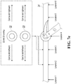
- FIG. 4 is a schematic diagram illustrating a user interface of a slider selector, according to the existing technology. For ease of viewing, appearances of the user interface in FIG. 4 and the user interface in FIG. 3 are the same.
- the slider selector in FIG. 4 includes a sliding track 31 ′, a right slider control 32 ′, and a left slider control 33 ′.
- the sliding track 31 ′ is configured to specify a ticket price interval, and a current ticket price subinterval selected by using the left slider control 33 ′ and the right slider control 32 ′ is [ ⁇ 2011 - ⁇ 3536 ], that is, a price subinterval corresponding to the dark-colored part of the sliding track 31 ′.
- a ticket price corresponding to a location of the left slider control 33 ′ is ⁇ 2011
- a ticket price corresponding to a location of the right slider control 32 is ⁇ 3536 .
- a scenario corresponding to FIG. 5 a to FIG. 5 c is the scenario described in the background.
- a user wants to slide the right slider control 32 ′ to a left side of the left slider control 33 ′.
- FIG. 5 a is a schematic diagram illustrating a first state corresponding to a controlling procedure of a slider control, according to the existing technology.
- the user starts to slide the right slider control 32 ′ leftward.
- FIG. 5 b is a schematic diagram illustrating a second state corresponding to a controlling procedure of a slider control, according to the existing technology.
- the user has slid the right slider control 32 ′ leftward to the location of the left slider control 33 ′, and the right slider control 32 ′ and the left slider control 33 ′ overlap (that is, the right slider control 32 ′ is located on the left slider control 33 ′).
- FIG. 5 c is a schematic diagram illustrating a third state corresponding to a controlling procedure of a slider control, according to the existing technology.
- the left slider control 33 ′ is not moved, the user cannot continue sliding the right slider control 32 ′ leftward. The user cannot slide the right slider control 32 ′ to the left side of the left slider control 33 ′.
- a scenario corresponding to FIG. 6 a to FIG. 6 c is also the scenario described in the background.
- FIG. 6 a is a schematic diagram illustrating a first state of a controlling procedure of a slider control, according to an implementation of the present application.
- a user starts to slide a first slider control 32 leftward.
- FIG. 6 b is a schematic diagram illustrating a second state of a controlling procedure of a slider control, according to an implementation of the present application.
- the user has slid the first slider control 32 leftward to a location of a second slider control 33 , and the first slider control 32 and the second slider control 33 overlap (that is, the first slider control 32 is located on the second slider control 33 ).
- FIG. 6 c is a schematic diagram illustrating a third state of a controlling procedure of a slider control, according to an implementation of the present application.
- the second slider control 33 does not need to be moved, and the user can continue sliding the first slider control 32 leftward.
- FIG. 6 d is a schematic diagram illustrating a fourth state of a controlling procedure of a slider control, according to an implementation of the present application.
- the user has slid the first slider control 32 from a right side of the second slider control 33 to the left side of the second slider control 33 by passing through the location of the second slider control 33 .
- FIG. 7 a to FIG. 7 g are used as an example to describe the effect in detail.
- some location points are marked on a sliding track for ease of description.
- FIG. 7 a is a schematic diagram illustrating a controlling scenario of a slider control in practice. Because the existing technology is going to be compared with the solutions of the present application in subsequent descriptions of FIG. 7 b to FIG. 7 g , a slider selector in FIG. 7 a can be the slider selector in the existing technology, or can be the slider selector in the solutions of the present application. Correspondingly, labels corresponding to the solutions of the present application and labels corresponding to the existing technology are separately marked on each part in FIG. 7 a.
- a slider control 32 ( 32 ′) is at location 5
- a slider control 33 ( 33 ′) is at location 4 .
- a user wants to slide the slider control 32 ( 32 ′) to location 3
- slide the slider control 33 ( 33 ′) to location 2 Assume that the user first slides the slider control 32 ( 32 ′).
- FIG. 7 b to FIG. 7 d correspond to the existing technology.
- FIG. 7 e to FIG. 7 g correspond to the solutions of the present application.
- FIG. 7 b is a schematic diagram illustrating a first state corresponding to a controlling procedure of a slider control for the scenario in FIG. 7 a , according to the existing technology.
- the user has slid the right slider control 32 ′ leftward to the location of the left slider control 33 ′ (that is, the location 4 ), and the right slider control 32 ′ and the left slider control 33 ′ overlap.
- the left slider control 33 ′ is not moved, the user cannot continue sliding the right slider control 32 ′ leftward. The user cannot slide the right slider control 32 ′ to a left side of the left slider control 33 ′.
- FIG. 7 c is a schematic diagram illustrating a second state corresponding to a controlling procedure of a slider control for the scenario in FIG. 7 a , according to the existing technology.
- FIG. 7 c because the user cannot continue sliding the right slider control 32 ′ leftward, an operation process is interrupted, and the user can only first slide the left slider control 33 ′ leftward to a target location (that is, the location 2 ).
- FIG. 7 d is a schematic diagram illustrating a third state corresponding to a controlling procedure of a slider control for the scenario in FIG. 7 a , according to the existing technology.
- the user can start to slide the right slider control 32 ′ leftward again, until the right slider control 32 ′ is slid to a target location (that is, the location 3 ).
- both the right slider control 32 ′ and the left slider control 33 ′ have been slid to the target locations.
- the operation process of the user is forced to be interrupted, and the user needs to perform three continuous operations in total.
- FIG. 7 e is a schematic diagram illustrating a first state corresponding to a controlling procedure of a slider control for the scenario in FIG. 7 a , according to an implementation of the present application.
- the user has slid the first slider control 32 leftward to the location of the second slider control 33 (that is, the location 4 ), and the first slider control 32 and the second slider control 33 overlap.
- FIG. 7 f is a schematic diagram illustrating a second state corresponding to a controlling procedure of a slider control for the scenario in FIG. 7 a , according to an implementation of the present application.
- an operation process can be uninterrupted. Even if the second slider control 33 is not moved, the user can still continue to slide the first slider control 32 leftward, until the first slider control 32 is slid to a target location (that is, the location 3 ).
- FIG. 7 g is a schematic diagram illustrating a third state corresponding to a controlling procedure of a slider control for the scenario in FIG. 7 a , according to an implementation of the present application.
- the user can slide the second slider control 33 from the location 4 to a target location (that is, the location 2 ) by passing through a current location of the first slider control 32 (that is, the location 3 ).
- both the first slider control 32 and the second slider control 33 have been slid to the target locations.
- the operation process of the user is not forcibly interrupted, and the user needs to perform only two continuous operations in total, which is less than a corresponding quantity of continuous operations in the existing technology.
- the solutions of the present application can be used to partially or completely resolve the problem in the existing technology.
- the solutions of the present application can be used to reduce operations of a user and improve operation experience of the user.
- the implementations of the present invention can be provided as a method, a system, or a computer program product. Therefore, the present invention can use a form of hardware only implementations, software only implementations, or implementations with a combination of software and hardware. Moreover, the present invention can use a form of a computer program product that is implemented on one or more computer-usable storage media (including but not limited to a disk memory, a CD-ROM, an optical memory, etc.) that include computer-usable program code.
- computer-usable storage media including but not limited to a disk memory, a CD-ROM, an optical memory, etc.
- These computer program indications can be provided for a general-purpose computer, a dedicated computer, an embedded processor, or a processor of any other programmable data processing device to generate a machine, so that the indications executed by a computer or a processor of any other programmable data processing device generate an apparatus for implementing a specific function in one or more processes in the flowcharts and/or in one or more blocks in the block diagrams.
- These computer program instructions can be stored in a computer readable memory that can instruct the computer or any other programmable data processing device to work in a specific way, so that the indications stored in the computer readable memory generate an artifact that includes an indication apparatus.
- the indication apparatus implements a specific function in one or more processes in the flowcharts and/or in one or more blocks in the block diagrams.
- a computing device includes one or more processors (CPU), an input/output interface, a network interface, and a memory.
- the memory can include a non-persistent memory, a random access memory (RAM), a non-volatile memory, and/or another form that are in a computer readable medium, for example, a read-only memory (ROM) or a flash memory (flash RAM).
- ROM read-only memory
- flash RAM flash memory
- the computer readable medium includes persistent, non-persistent, movable, and unmovable media that can implement information storage by using any method or technology.
- Information can be a computer readable instruction, a data structure, a program module, or other data.
- An example of a computer storage medium includes but is not limited to a phase-change random access memory (PRAM), a static random access memory (SRAM), a dynamic random access memory (DRAM), another type of random access memory (RAM), a read-only memory (ROM), an electrically erasable programmable read-only memory (EEPROM), a flash memory or another memory technology, a compact disc read-only memory (CD-ROM), a digital versatile disc (DVD) or other optical storage, a cassette magnetic tape, tape and disk storage or another magnetic storage device or any other non-transmission media that can be used to store information that a computing device can access.
- the computer readable medium does not include a transitory computer readable medium (transitory media), for example, a modulated data signal
- the terms “include”, “comprise”, or their any other variant are intended to cover a non-exclusive inclusion, so that a process, a method, an article, or a device that includes a list of elements not only includes those elements but also includes other elements which are not expressly listed, or further includes elements inherent to such process, method, article, or device.
- An element preceded by “includes a . . . ” does not, without more constraints, preclude the presence of additional identical elements in the process, method, article, or device that includes the element.
- FIG. 8 is a flowchart illustrating an example of a computer-implemented method 800 for controlling a sliding control, according to an implementation of the present disclosure.
- method 800 can be performed, for example, by any system, environment, software, and hardware, or a combination of systems, environments, software, and hardware, as appropriate.
- various steps of method 800 can be run in parallel, in combination, in loops, or in any order.
- a first sliding control and a second sliding control are provided for presentation, such as at a user interface.
- the first sliding control can be located on a first side of the second sliding control initially, or at any point.
- the first side and the second side of the second sliding control may be any suitable side of a presentation.
- the first sliding control and the second sliding control may be located on a single sliding track, although any suitable configuration may be possible.
- the first side of the second sliding control can be a portion of the sliding track on one side of the second control, while the second side of the second sliding control can be a portion of the sliding track on the other, or opposite side of the second sliding control. From 802 , method 800 proceeds to 804 .
- an instruction associated with the first sliding control is received, where the instruction instructs the first sliding control to be slid to a second side of the second sliding control.
- the instruction may be received, for example, via a drag operation received via the user interface, or may be an automated instruction such as those used in testing.
- the drag operation may be a touch-based or touch-related input using a touchscreen, or the drag operation may be received via another peripheral, such as a mouse or other input device. From 804 , method 800 proceeds to 806 .
- the first sliding control is slid to the second side of the second sliding control based on the received instruction.
- sliding the first sliding control to the second side of the second sliding control may be performed by moving the first sliding control through a location at which the second sliding control is located.
- sliding the first sliding control to the second side of the second sliding control may be performed by bypassing, or skipping over or around, a location at which the second sliding control is located. Sliding the first sliding control can cause the presentation to update with a new location of where the first sliding control ends after or based on the instruction. From 806 , method 800 proceeds to 808 .
- a determination can be made, based on the location of the first sliding control after its sliding and the location of the second sliding control, a particular selection associated with the respective locations of the controls.
- the sliding track may be used to specify a value interval.
- the particular locations of the first and second sliding controls can be used to select a value subinterval from the value interval.
- first sliding control and the second sliding control are slider controls.
- first and second sliding controls may be sliding handle controls used to select a page element displayed on a page in which the first and second sliding controls are located. Based on the location of the sliding controls, a particular page element to be selected is determined. After 808 , method 800 can stop.
- the present solution can provide a better user experience, as user inputs and interactions can be reduced by allowing controls to be moved to any location on a slider.
- the operation allows for a reduction in sliding distances of the first sliding control, thus reducing operation time.
- the first sliding control can be straight slid (in a shortest sliding distance) from one side of the second sliding control to the other side of the second sliding control, using a straight direct line between the first sliding control and the second sliding control and an extended line of the straight line as a sliding track of the first sliding track.
- Embodiments and the operations described in this specification can be implemented in digital electronic circuitry, or in computer software, firmware, or hardware, including the structures disclosed in this specification or in combinations of one or more of them.
- the operations can be implemented as operations performed by a data processing apparatus on data stored on one or more computer-readable storage devices or received from other sources.
- a data processing apparatus, computer, or computing device may encompass apparatus, devices, and machines for processing data, including by way of example a programmable processor, a computer, a system on a chip, or multiple ones, or combinations, of the foregoing.
- the apparatus can include special purpose logic circuitry, for example, a central processing unit (CPU), a field programmable gate array (FPGA) or an application-specific integrated circuit (ASIC).
- CPU central processing unit
- FPGA field programmable gate array
- ASIC application-specific integrated circuit
- the apparatus can also include code that creates an execution environment for the computer program in question, for example, code that constitutes processor firmware, a protocol stack, a database management system, an operating system (for example an operating system or a combination of operating systems), a cross-platform runtime environment, a virtual machine, or a combination of one or more of them.
- the apparatus and execution environment can realize various different computing model infrastructures, such as web services, distributed computing and grid computing infrastructures.
- a computer program (also known, for example, as a program, software, software application, software module, software unit, script, or code) can be written in any form of programming language, including compiled or interpreted languages, declarative or procedural languages, and it can be deployed in any form, including as a stand-alone program or as a module, component, subroutine, object, or other unit suitable for use in a computing environment.
- a program can be stored in a portion of a file that holds other programs or data (for example, one or more scripts stored in a markup language document), in a single file dedicated to the program in question, or in multiple coordinated files (for example, files that store one or more modules, sub-programs, or portions of code).
- a computer program can be executed on one computer or on multiple computers that are located at one site or distributed across multiple sites and interconnected by a communication network.
- processors for execution of a computer program include, by way of example, both general- and special-purpose microprocessors, and any one or more processors of any kind of digital computer.
- a processor will receive instructions and data from a read-only memory or a random-access memory or both.
- the essential elements of a computer are a processor for performing actions in accordance with instructions and one or more memory devices for storing instructions and data.
- a computer will also include, or be operatively coupled to receive data from or transfer data to, or both, one or more mass storage devices for storing data.
- a computer can be embedded in another device, for example, a mobile device, a personal digital assistant (PDA), a game console, a Global Positioning System (GPS) receiver, or a portable storage device.
- PDA personal digital assistant
- GPS Global Positioning System
- Devices suitable for storing computer program instructions and data include non-volatile memory, media and memory devices, including, by way of example, semiconductor memory devices, magnetic disks, and magneto-optical disks.
- the processor and the memory can be supplemented by, or incorporated in, special-purpose logic circuitry.
- Mobile devices can include handsets, user equipment (UE), mobile telephones (for example, smartphones), tablets, wearable devices (for example, smart watches and smart eyeglasses), implanted devices within the human body (for example, biosensors, cochlear implants), or other types of mobile devices.
- the mobile devices can communicate wirelessly (for example, using radio frequency (RF) signals) to various communication networks (described below).
- RF radio frequency
- the mobile devices can include sensors for determining characteristics of the mobile device's current environment.
- the sensors can include cameras, microphones, proximity sensors, GPS sensors, motion sensors, accelerometers, ambient light sensors, moisture sensors, gyroscopes, compasses, barometers, fingerprint sensors, facial recognition systems, RF sensors (for example, Wi-Fi and cellular radios), thermal sensors, or other types of sensors.
- the cameras can include a forward- or rear-facing camera with movable or fixed lenses, a flash, an image sensor, and an image processor.
- the camera can be a megapixel camera capable of capturing details for facial and/or iris recognition.
- the camera along with a data processor and authentication information stored in memory or accessed remotely can form a facial recognition system.
- the facial recognition system or one-or-more sensors for example, microphones, motion sensors, accelerometers, GPS sensors, or RF sensors, can be used for user authentication.
- embodiments can be implemented on a computer having a display device and an input device, for example, a liquid crystal display (LCD) or organic light-emitting diode (OLED)/virtual-reality (VR)/augmented-reality (AR) display for displaying information to the user and a touchscreen, keyboard, and a pointing device by which the user can provide input to the computer.
- LCD liquid crystal display
- OLED organic light-emitting diode
- VR virtual-reality
- AR pointing device
- Other kinds of devices can be used to provide for interaction with a user as well; for example, feedback provided to the user can be any form of sensory feedback, for example, visual feedback, auditory feedback, or tactile feedback; and input from the user can be received in any form, including acoustic, speech, or tactile input.
- a computer can interact with a user by sending documents to and receiving documents from a device that is used by the user; for example, by sending web pages to a web browser on a user's client device in response
- Embodiments can be implemented using computing devices interconnected by any form or medium of wireline or wireless digital data communication (or combination thereof), for example, a communication network.
- interconnected devices are a client and a server generally remote from each other that typically interact through a communication network.
- a client for example, a mobile device, can carry out transactions itself, with a server, or through a server, for example, performing buy, sell, pay, give, send, or loan transactions, or authorizing the same.
- Such transactions may be in real time such that an action and a response are temporally proximate; for example an individual perceives the action and the response occurring substantially simultaneously, the time difference for a response following the individual's action is less than 1 millisecond (ms) or less than 1 second (s), or the response is without intentional delay taking into account processing limitations of the system.
- ms millisecond
- s 1 second
- Examples of communication networks include a local area network (LAN), a radio access network (RAN), a metropolitan area network (MAN), and a wide area network (WAN).
- the communication network can include all or a portion of the Internet, another communication network, or a combination of communication networks.
- Information can be transmitted on the communication network according to various protocols and standards, including Long Term Evolution (LTE), 5G, IEEE 802, Internet Protocol (IP), or other protocols or combinations of protocols.
- LTE Long Term Evolution
- 5G Fifth Generation
- IEEE 802 Internet Protocol
- IP Internet Protocol
- the communication network can transmit voice, video, biometric, or authentication data, or other information between the connected computing devices.
Abstract
Description
Claims (21)
Priority Applications (1)
| Application Number | Priority Date | Filing Date | Title |
|---|---|---|---|
| US16/721,428 US10782867B2 (en) | 2016-06-28 | 2019-12-19 | Controlling method and device for slider control, and slider selector |
Applications Claiming Priority (6)
| Application Number | Priority Date | Filing Date | Title |
|---|---|---|---|
| CN201610494357.9 | 2016-06-28 | ||
| CN201610494357 | 2016-06-28 | ||
| CN201610494357.9A CN106896997B (en) | 2016-06-28 | 2016-06-28 | Sliding control method and device and sliding block selector |
| PCT/CN2017/088548 WO2018001115A1 (en) | 2016-06-28 | 2017-06-16 | Controlling method and device for slider control and slider selector |
| US16/234,467 US10782866B2 (en) | 2016-06-28 | 2018-12-27 | Controlling method and device for slider control, and slider selector |
| US16/721,428 US10782867B2 (en) | 2016-06-28 | 2019-12-19 | Controlling method and device for slider control, and slider selector |
Related Parent Applications (1)
| Application Number | Title | Priority Date | Filing Date |
|---|---|---|---|
| US16/234,467 Continuation US10782866B2 (en) | 2016-06-28 | 2018-12-27 | Controlling method and device for slider control, and slider selector |
Publications (2)
| Publication Number | Publication Date |
|---|---|
| US20200125248A1 US20200125248A1 (en) | 2020-04-23 |
| US10782867B2 true US10782867B2 (en) | 2020-09-22 |
Family
ID=59190565
Family Applications (2)
| Application Number | Title | Priority Date | Filing Date |
|---|---|---|---|
| US16/234,467 Active 2037-06-17 US10782866B2 (en) | 2016-06-28 | 2018-12-27 | Controlling method and device for slider control, and slider selector |
| US16/721,428 Active US10782867B2 (en) | 2016-06-28 | 2019-12-19 | Controlling method and device for slider control, and slider selector |
Family Applications Before (1)
| Application Number | Title | Priority Date | Filing Date |
|---|---|---|---|
| US16/234,467 Active 2037-06-17 US10782866B2 (en) | 2016-06-28 | 2018-12-27 | Controlling method and device for slider control, and slider selector |
Country Status (10)
| Country | Link |
|---|---|
| US (2) | US10782866B2 (en) |
| EP (1) | EP3477450A4 (en) |
| JP (1) | JP6784784B2 (en) |
| KR (1) | KR102230429B1 (en) |
| CN (1) | CN106896997B (en) |
| MY (1) | MY193311A (en) |
| PH (1) | PH12019500007A1 (en) |
| SG (1) | SG11201811558QA (en) |
| TW (1) | TWI656473B (en) |
| WO (1) | WO2018001115A1 (en) |
Families Citing this family (6)
| Publication number | Priority date | Publication date | Assignee | Title |
|---|---|---|---|---|
| CN106896997B (en) | 2016-06-28 | 2020-11-10 | 创新先进技术有限公司 | Sliding control method and device and sliding block selector |
| CN108319490B (en) | 2018-03-01 | 2019-04-05 | 网易(杭州)网络有限公司 | Numerical value determines method, numerical value determining device, electronic equipment and storage medium |
| CN110604580A (en) * | 2018-10-23 | 2019-12-24 | 深圳迈瑞生物医疗电子股份有限公司 | Medical equipment, and interval threshold setting method and device for medical equipment |
| CN113608666A (en) * | 2021-08-11 | 2021-11-05 | 平安国际智慧城市科技股份有限公司 | Hierarchical control method, device, medium and equipment based on sliding operation |
| CN114489456B (en) * | 2022-01-04 | 2024-01-30 | 杭州涂鸦信息技术有限公司 | Lighting system control method, lighting system control device, computer device, and readable storage medium |
| CN115599278A (en) * | 2022-11-25 | 2023-01-13 | 三亚海兰寰宇海洋信息科技有限公司(Cn) | Method, device and equipment for setting navigational speed threshold of target object |
Citations (31)
| Publication number | Priority date | Publication date | Assignee | Title |
|---|---|---|---|---|
| US5867678A (en) * | 1996-12-16 | 1999-02-02 | International Business Machines Corporation | Method and system for searching and retrieving specific types of objects contained within a compound document |
| US5874961A (en) * | 1997-03-19 | 1999-02-23 | International Business Machines Corporation | Scroll bar amplification apparatus and method |
| US6204846B1 (en) * | 1999-02-16 | 2001-03-20 | International Business Machines Corporation | Data set user interface control for use in accessing information in a computer |
| US20050094014A1 (en) * | 2003-11-03 | 2005-05-05 | Haas William R. | Slider bar interface for digital camera |
| US20080165141A1 (en) * | 2007-01-05 | 2008-07-10 | Apple Inc. | Gestures for controlling, manipulating, and editing of media files using touch sensitive devices |
| US20080256489A1 (en) | 2007-04-16 | 2008-10-16 | Tektronix, Inc. | Range Sliders with Linked Auto-Updating Spans |
| US7562310B2 (en) | 2006-04-04 | 2009-07-14 | International Business Machines Corporation | Slider control movable in a two-dimensional region for simultaneously adjusting values of multiple variables |
| US20090241072A1 (en) * | 2005-12-23 | 2009-09-24 | Imran Chaudhri | Unlocking a Device by Performing Gestures on an Unlock Image |
| US20090282362A1 (en) * | 2008-05-07 | 2009-11-12 | Hoya Corporation | Graphic system displaying scroll bar |
| US20100306704A1 (en) | 2005-11-16 | 2010-12-02 | Stephen Cotterill | User Interface Widget For Selecting A Point Or Range |
| US20110025924A1 (en) * | 2009-07-30 | 2011-02-03 | VIZIO Inc. | Dual slider bar control |
| CN101980136A (en) | 2010-11-08 | 2011-02-23 | 广东欧珀移动通信有限公司 | Sliding control interaction method for handheld terminal |
| US20110167347A1 (en) | 2010-01-06 | 2011-07-07 | Samsung Electronics Co. Ltd. | Method and apparatus for setting section of a multimedia file in mobile device |
| US8018432B1 (en) * | 2007-04-20 | 2011-09-13 | Adobe Systems Incorporated | User interfaces and methods to search content in a nonlinearly convergent manner |
| US20120280922A1 (en) * | 2011-05-02 | 2012-11-08 | Samsung Electronics Co., Ltd. | Method for finely controlling contents and portable terminal supporting the same |
| US20130159922A1 (en) * | 2011-12-16 | 2013-06-20 | International Business Machines Corporation | Scroll focus |
| US20130239057A1 (en) | 2012-03-06 | 2013-09-12 | Apple Inc. | Unified slider control for modifying multiple image properties |
| CN103383621A (en) | 2012-05-04 | 2013-11-06 | 腾讯科技(深圳)有限公司 | Method and device for view switching |
| US20140007011A1 (en) * | 2012-06-18 | 2014-01-02 | Allen Learning Technologies | Event flow user interface |
| TW201409346A (en) | 2012-08-23 | 2014-03-01 | Egalax Empia Technology Inc | Method for displaying graphical user interface and electronic device using the same |
| CN103793125A (en) | 2012-10-29 | 2014-05-14 | 柯尼卡美能达株式会社 | Display apparatus accepting scroll operation |
| TW201426571A (en) | 2012-12-20 | 2014-07-01 | Inst Information Industry | Touch control method and handheld device |
| US8826192B1 (en) * | 2012-02-22 | 2014-09-02 | Google Inc. | Graphical method of inputting parameter ranges |
| US20140258854A1 (en) * | 2012-05-31 | 2014-09-11 | Eric Qing Li | Method and apparatus for snapping to predefined locations on a scroll bar while navigating through a media program |
| CN104142789A (en) | 2013-05-07 | 2014-11-12 | 腾讯科技(深圳)有限公司 | Content selection method, content selection device and terminal |
| US20140337799A1 (en) | 2013-05-07 | 2014-11-13 | Tencent Technology (Shenzhen) Company Limited | Method, apparatus and terminal for selecting content |
| CN104350495A (en) | 2012-06-07 | 2015-02-11 | 微软公司 | Managing objects in panorama display to navigate spreadsheet |
| CN104935725A (en) | 2015-04-23 | 2015-09-23 | 努比亚技术有限公司 | Mobile terminal and method for realizing function adjustment by utilizing virtual frame areas of mobile terminal |
| US20160054896A1 (en) * | 2014-08-25 | 2016-02-25 | Canon Kabushiki Kaisha | Electronic apparatus and method for controlling the same |
| US20180329461A1 (en) * | 2017-05-15 | 2018-11-15 | Microsoft Technology Licensing, Llc | Volume adjustment on hinged multi-screen device |
| US20190155491A1 (en) | 2016-06-28 | 2019-05-23 | Alibaba Group Holding Limited | Controlling method and device for slider control, and slider selector |
-
2016
- 2016-06-28 CN CN201610494357.9A patent/CN106896997B/en active Active
-
2017
- 2017-04-14 TW TW106112618A patent/TWI656473B/en active
- 2017-06-16 SG SG11201811558QA patent/SG11201811558QA/en unknown
- 2017-06-16 WO PCT/CN2017/088548 patent/WO2018001115A1/en unknown
- 2017-06-16 JP JP2018568910A patent/JP6784784B2/en active Active
- 2017-06-16 KR KR1020197002655A patent/KR102230429B1/en active IP Right Grant
- 2017-06-16 MY MYPI2018002918A patent/MY193311A/en unknown
- 2017-06-16 EP EP17819112.8A patent/EP3477450A4/en not_active Withdrawn
-
2018
- 2018-12-27 US US16/234,467 patent/US10782866B2/en active Active
-
2019
- 2019-01-03 PH PH12019500007A patent/PH12019500007A1/en unknown
- 2019-12-19 US US16/721,428 patent/US10782867B2/en active Active
Patent Citations (31)
| Publication number | Priority date | Publication date | Assignee | Title |
|---|---|---|---|---|
| US5867678A (en) * | 1996-12-16 | 1999-02-02 | International Business Machines Corporation | Method and system for searching and retrieving specific types of objects contained within a compound document |
| US5874961A (en) * | 1997-03-19 | 1999-02-23 | International Business Machines Corporation | Scroll bar amplification apparatus and method |
| US6204846B1 (en) * | 1999-02-16 | 2001-03-20 | International Business Machines Corporation | Data set user interface control for use in accessing information in a computer |
| US20050094014A1 (en) * | 2003-11-03 | 2005-05-05 | Haas William R. | Slider bar interface for digital camera |
| US20100306704A1 (en) | 2005-11-16 | 2010-12-02 | Stephen Cotterill | User Interface Widget For Selecting A Point Or Range |
| US20090241072A1 (en) * | 2005-12-23 | 2009-09-24 | Imran Chaudhri | Unlocking a Device by Performing Gestures on an Unlock Image |
| US7562310B2 (en) | 2006-04-04 | 2009-07-14 | International Business Machines Corporation | Slider control movable in a two-dimensional region for simultaneously adjusting values of multiple variables |
| US20080165141A1 (en) * | 2007-01-05 | 2008-07-10 | Apple Inc. | Gestures for controlling, manipulating, and editing of media files using touch sensitive devices |
| US20080256489A1 (en) | 2007-04-16 | 2008-10-16 | Tektronix, Inc. | Range Sliders with Linked Auto-Updating Spans |
| US8018432B1 (en) * | 2007-04-20 | 2011-09-13 | Adobe Systems Incorporated | User interfaces and methods to search content in a nonlinearly convergent manner |
| US20090282362A1 (en) * | 2008-05-07 | 2009-11-12 | Hoya Corporation | Graphic system displaying scroll bar |
| US20110025924A1 (en) * | 2009-07-30 | 2011-02-03 | VIZIO Inc. | Dual slider bar control |
| US20110167347A1 (en) | 2010-01-06 | 2011-07-07 | Samsung Electronics Co. Ltd. | Method and apparatus for setting section of a multimedia file in mobile device |
| CN101980136A (en) | 2010-11-08 | 2011-02-23 | 广东欧珀移动通信有限公司 | Sliding control interaction method for handheld terminal |
| US20120280922A1 (en) * | 2011-05-02 | 2012-11-08 | Samsung Electronics Co., Ltd. | Method for finely controlling contents and portable terminal supporting the same |
| US20130159922A1 (en) * | 2011-12-16 | 2013-06-20 | International Business Machines Corporation | Scroll focus |
| US8826192B1 (en) * | 2012-02-22 | 2014-09-02 | Google Inc. | Graphical method of inputting parameter ranges |
| US20130239057A1 (en) | 2012-03-06 | 2013-09-12 | Apple Inc. | Unified slider control for modifying multiple image properties |
| CN103383621A (en) | 2012-05-04 | 2013-11-06 | 腾讯科技(深圳)有限公司 | Method and device for view switching |
| US20140258854A1 (en) * | 2012-05-31 | 2014-09-11 | Eric Qing Li | Method and apparatus for snapping to predefined locations on a scroll bar while navigating through a media program |
| CN104350495A (en) | 2012-06-07 | 2015-02-11 | 微软公司 | Managing objects in panorama display to navigate spreadsheet |
| US20140007011A1 (en) * | 2012-06-18 | 2014-01-02 | Allen Learning Technologies | Event flow user interface |
| TW201409346A (en) | 2012-08-23 | 2014-03-01 | Egalax Empia Technology Inc | Method for displaying graphical user interface and electronic device using the same |
| CN103793125A (en) | 2012-10-29 | 2014-05-14 | 柯尼卡美能达株式会社 | Display apparatus accepting scroll operation |
| TW201426571A (en) | 2012-12-20 | 2014-07-01 | Inst Information Industry | Touch control method and handheld device |
| CN104142789A (en) | 2013-05-07 | 2014-11-12 | 腾讯科技(深圳)有限公司 | Content selection method, content selection device and terminal |
| US20140337799A1 (en) | 2013-05-07 | 2014-11-13 | Tencent Technology (Shenzhen) Company Limited | Method, apparatus and terminal for selecting content |
| US20160054896A1 (en) * | 2014-08-25 | 2016-02-25 | Canon Kabushiki Kaisha | Electronic apparatus and method for controlling the same |
| CN104935725A (en) | 2015-04-23 | 2015-09-23 | 努比亚技术有限公司 | Mobile terminal and method for realizing function adjustment by utilizing virtual frame areas of mobile terminal |
| US20190155491A1 (en) | 2016-06-28 | 2019-05-23 | Alibaba Group Holding Limited | Controlling method and device for slider control, and slider selector |
| US20180329461A1 (en) * | 2017-05-15 | 2018-11-15 | Microsoft Technology Licensing, Llc | Volume adjustment on hinged multi-screen device |
Non-Patent Citations (6)
| Title |
|---|
| Crosby et al., "BlockChain Technology: Beyond Bitcoin," Sutardja Center for Entrepreneurship & Technology Technical Report, Oct. 16, 2015, 35 pages. |
| European Extended Search Report in European Patent Application No. 17819112.8, dated May 22, 2019, 10 pages. |
| Gocalf.com [online], "iOS Custom Range Slider Control," Last Updated on Dec. 2012, [Retrieved on May 24, 2019], Retrieved from: URL<http://www.gocalf.com/blog/iphone-dev-range-slider.html>, 18 pages (with Machine English Translation). |
| International Preliminary Report on Patentability in International Application No. PCT/CN2017/088548 dated Jan. 1, 2019; 8 pages. |
| International Search Report by the International Searching Authority issued in International Application No. PCT/CN2017/088548 dated Sep. 18, 2017 13 pages. |
| Nakamoto, "Bitcoin: A Peer-to-Peer Electronic Cash System," www.bitcoin.org, 2005, 9 pages. |
Also Published As
| Publication number | Publication date |
|---|---|
| MY193311A (en) | 2022-10-04 |
| TW201800927A (en) | 2018-01-01 |
| TWI656473B (en) | 2019-04-11 |
| WO2018001115A1 (en) | 2018-01-04 |
| JP2019526116A (en) | 2019-09-12 |
| CN106896997A (en) | 2017-06-27 |
| US20200125248A1 (en) | 2020-04-23 |
| CN106896997B (en) | 2020-11-10 |
| KR20190020816A (en) | 2019-03-04 |
| US10782866B2 (en) | 2020-09-22 |
| US20190155491A1 (en) | 2019-05-23 |
| KR102230429B1 (en) | 2021-03-24 |
| JP6784784B2 (en) | 2020-11-11 |
| EP3477450A4 (en) | 2019-06-19 |
| PH12019500007A1 (en) | 2019-10-14 |
| EP3477450A1 (en) | 2019-05-01 |
| SG11201811558QA (en) | 2019-01-30 |
Similar Documents
| Publication | Publication Date | Title |
|---|---|---|
| US10782867B2 (en) | Controlling method and device for slider control, and slider selector | |
| US10963152B2 (en) | Map interface interaction | |
| US11157585B2 (en) | Information display method and device | |
| US10686789B2 (en) | Multi-blockchain network data processing | |
| US11100442B2 (en) | Method and device for implementing service function | |
| US10691794B2 (en) | Method, apparatus, and electronic device for detecting model security | |
| US20200143272A1 (en) | Terminal rule operation device and method | |
| US10789420B2 (en) | Mixed view display method and device | |
| US20190279425A1 (en) | Augmented-reality-based offline interaction method and apparatus | |
| KR102248474B1 (en) | Voice command providing method and apparatus | |
| US10884767B2 (en) | Service processing methods and devices | |
| US10573053B2 (en) | Method and apparatus for animating images on mobile devices | |
| US10930026B2 (en) | Method and apparatus for realizing color tween animation | |
| US11061468B2 (en) | Method and device for inputting password in virtual reality scene | |
| US11212639B2 (en) | Information display method and apparatus | |
| US20190102061A1 (en) | Method and device for processing group message | |
| US20200125223A1 (en) | Method, device, apparatus, and system for displaying dynamic list | |
| US11019453B2 (en) | Method and apparatus for determining relative location | |
| US10664160B2 (en) | Method and apparatus for implementing accessibility function in applications | |
| US11796810B2 (en) | Indication of presence awareness |
Legal Events
| Date | Code | Title | Description |
|---|---|---|---|
| FEPP | Fee payment procedure |
Free format text: ENTITY STATUS SET TO UNDISCOUNTED (ORIGINAL EVENT CODE: BIG.); ENTITY STATUS OF PATENT OWNER: LARGE ENTITY |
|
| AS | Assignment |
Owner name: ALIBABA GROUP HOLDING LIMITED, CAYMAN ISLANDS Free format text: ASSIGNMENT OF ASSIGNORS INTEREST;ASSIGNORS:ZHU, XINGMIN;LIN, XIAOQING;REEL/FRAME:051615/0518 Effective date: 20190219 |
|
| STPP | Information on status: patent application and granting procedure in general |
Free format text: RESPONSE TO NON-FINAL OFFICE ACTION ENTERED AND FORWARDED TO EXAMINER |
|
| STPP | Information on status: patent application and granting procedure in general |
Free format text: PUBLICATIONS -- ISSUE FEE PAYMENT RECEIVED |
|
| AS | Assignment |
Owner name: ADVANTAGEOUS NEW TECHNOLOGIES CO., LTD., CAYMAN ISLANDS Free format text: ASSIGNMENT OF ASSIGNORS INTEREST;ASSIGNOR:ALIBABA GROUP HOLDING LIMITED;REEL/FRAME:053743/0464 Effective date: 20200826 |
|
| STCF | Information on status: patent grant |
Free format text: PATENTED CASE |
|
| AS | Assignment |
Owner name: ADVANCED NEW TECHNOLOGIES CO., LTD., CAYMAN ISLANDS Free format text: ASSIGNMENT OF ASSIGNORS INTEREST;ASSIGNOR:ADVANTAGEOUS NEW TECHNOLOGIES CO., LTD.;REEL/FRAME:053754/0625 Effective date: 20200910 |
|
| MAFP | Maintenance fee payment |
Free format text: PAYMENT OF MAINTENANCE FEE, 4TH YEAR, LARGE ENTITY (ORIGINAL EVENT CODE: M1551); ENTITY STATUS OF PATENT OWNER: LARGE ENTITY Year of fee payment: 4 |