US10775128B2 - Spraying device - Google Patents
Spraying device Download PDFInfo
- Publication number
- US10775128B2 US10775128B2 US16/472,555 US201716472555A US10775128B2 US 10775128 B2 US10775128 B2 US 10775128B2 US 201716472555 A US201716472555 A US 201716472555A US 10775128 B2 US10775128 B2 US 10775128B2
- Authority
- US
- United States
- Prior art keywords
- hand
- projectile
- distance
- held unit
- propulsion drive
- Prior art date
- Legal status (The legal status is an assumption and is not a legal conclusion. Google has not performed a legal analysis and makes no representation as to the accuracy of the status listed.)
- Active
Links
- 238000005507 spraying Methods 0.000 title description 5
- 239000012530 fluid Substances 0.000 claims abstract description 184
- 239000007787 solid Substances 0.000 claims abstract description 12
- 238000010304 firing Methods 0.000 claims description 45
- 238000000034 method Methods 0.000 claims description 9
- XLYOFNOQVPJJNP-UHFFFAOYSA-N water Substances O XLYOFNOQVPJJNP-UHFFFAOYSA-N 0.000 description 38
- 230000002572 peristaltic effect Effects 0.000 description 15
- 230000008901 benefit Effects 0.000 description 14
- 239000007789 gas Substances 0.000 description 12
- 239000002917 insecticide Substances 0.000 description 10
- 208000027418 Wounds and injury Diseases 0.000 description 7
- 230000006378 damage Effects 0.000 description 7
- 230000000694 effects Effects 0.000 description 7
- 208000014674 injury Diseases 0.000 description 7
- 239000007921 spray Substances 0.000 description 7
- 238000011109 contamination Methods 0.000 description 6
- 239000007788 liquid Substances 0.000 description 6
- 230000001105 regulatory effect Effects 0.000 description 6
- 208000020564 Eye injury Diseases 0.000 description 5
- 238000004519 manufacturing process Methods 0.000 description 5
- 239000012459 cleaning agent Substances 0.000 description 4
- 230000001276 controlling effect Effects 0.000 description 4
- 230000005291 magnetic effect Effects 0.000 description 4
- 238000005259 measurement Methods 0.000 description 4
- 239000003973 paint Substances 0.000 description 4
- 239000003380 propellant Substances 0.000 description 4
- 239000000126 substance Substances 0.000 description 4
- 230000001133 acceleration Effects 0.000 description 3
- 230000008878 coupling Effects 0.000 description 3
- 238000010168 coupling process Methods 0.000 description 3
- 238000005859 coupling reaction Methods 0.000 description 3
- 239000004033 plastic Substances 0.000 description 3
- 238000003860 storage Methods 0.000 description 3
- 241000272201 Columbiformes Species 0.000 description 2
- 241000238631 Hexapoda Species 0.000 description 2
- 241000256856 Vespidae Species 0.000 description 2
- 239000004927 clay Substances 0.000 description 2
- 238000010276 construction Methods 0.000 description 2
- 238000001746 injection moulding Methods 0.000 description 2
- 239000000314 lubricant Substances 0.000 description 2
- 230000007246 mechanism Effects 0.000 description 2
- 230000035484 reaction time Effects 0.000 description 2
- 230000009467 reduction Effects 0.000 description 2
- 241000251468 Actinopterygii Species 0.000 description 1
- 229920001875 Ebonite Polymers 0.000 description 1
- 241001465754 Metazoa Species 0.000 description 1
- 229920006329 Styropor Polymers 0.000 description 1
- 230000006978 adaptation Effects 0.000 description 1
- 238000000889 atomisation Methods 0.000 description 1
- 230000008859 change Effects 0.000 description 1
- 239000002131 composite material Substances 0.000 description 1
- 230000006835 compression Effects 0.000 description 1
- 238000007906 compression Methods 0.000 description 1
- 238000007599 discharging Methods 0.000 description 1
- 238000006073 displacement reaction Methods 0.000 description 1
- 239000002979 fabric softener Substances 0.000 description 1
- 230000005294 ferromagnetic effect Effects 0.000 description 1
- GNBHRKFJIUUOQI-UHFFFAOYSA-N fluorescein Chemical compound O1C(=O)C2=CC=CC=C2C21C1=CC=C(O)C=C1OC1=CC(O)=CC=C21 GNBHRKFJIUUOQI-UHFFFAOYSA-N 0.000 description 1
- 239000006260 foam Substances 0.000 description 1
- 230000005484 gravity Effects 0.000 description 1
- 239000008266 hair spray Substances 0.000 description 1
- 239000011796 hollow space material Substances 0.000 description 1
- 239000003550 marker Substances 0.000 description 1
- 239000007769 metal material Substances 0.000 description 1
- 239000003595 mist Substances 0.000 description 1
- 229920001296 polysiloxane Polymers 0.000 description 1
- 238000007789 sealing Methods 0.000 description 1
- 239000002453 shampoo Substances 0.000 description 1
- 239000000779 smoke Substances 0.000 description 1
- 239000002904 solvent Substances 0.000 description 1
- 238000009987 spinning Methods 0.000 description 1
- 230000003068 static effect Effects 0.000 description 1
- 230000001960 triggered effect Effects 0.000 description 1
Images


Classifications
-
- F—MECHANICAL ENGINEERING; LIGHTING; HEATING; WEAPONS; BLASTING
- F41—WEAPONS
- F41H—ARMOUR; ARMOURED TURRETS; ARMOURED OR ARMED VEHICLES; MEANS OF ATTACK OR DEFENCE, e.g. CAMOUFLAGE, IN GENERAL
- F41H9/00—Equipment for attack or defence by spreading flame, gas or smoke or leurres; Chemical warfare equipment
- F41H9/10—Hand-held or body-worn self-defence devices using repellant gases or chemicals
-
- F—MECHANICAL ENGINEERING; LIGHTING; HEATING; WEAPONS; BLASTING
- F41—WEAPONS
- F41B—WEAPONS FOR PROJECTING MISSILES WITHOUT USE OF EXPLOSIVE OR COMBUSTIBLE PROPELLANT CHARGE; WEAPONS NOT OTHERWISE PROVIDED FOR
- F41B11/00—Compressed-gas guns, e.g. air guns; Steam guns
- F41B11/60—Compressed-gas guns, e.g. air guns; Steam guns characterised by the supply of compressed gas
- F41B11/62—Compressed-gas guns, e.g. air guns; Steam guns characterised by the supply of compressed gas with pressure supplied by a gas cartridge
-
- B—PERFORMING OPERATIONS; TRANSPORTING
- B05—SPRAYING OR ATOMISING IN GENERAL; APPLYING FLUENT MATERIALS TO SURFACES, IN GENERAL
- B05B—SPRAYING APPARATUS; ATOMISING APPARATUS; NOZZLES
- B05B12/00—Arrangements for controlling delivery; Arrangements for controlling the spray area
- B05B12/08—Arrangements for controlling delivery; Arrangements for controlling the spray area responsive to condition of liquid or other fluent material to be discharged, of ambient medium or of target ; responsive to condition of spray devices or of supply means, e.g. pipes, pumps or their drive means
- B05B12/12—Arrangements for controlling delivery; Arrangements for controlling the spray area responsive to condition of liquid or other fluent material to be discharged, of ambient medium or of target ; responsive to condition of spray devices or of supply means, e.g. pipes, pumps or their drive means responsive to conditions of ambient medium or target, e.g. humidity, temperature position or movement of the target relative to the spray apparatus
- B05B12/124—Arrangements for controlling delivery; Arrangements for controlling the spray area responsive to condition of liquid or other fluent material to be discharged, of ambient medium or of target ; responsive to condition of spray devices or of supply means, e.g. pipes, pumps or their drive means responsive to conditions of ambient medium or target, e.g. humidity, temperature position or movement of the target relative to the spray apparatus responsive to distance between spray apparatus and target
-
- F—MECHANICAL ENGINEERING; LIGHTING; HEATING; WEAPONS; BLASTING
- F41—WEAPONS
- F41B—WEAPONS FOR PROJECTING MISSILES WITHOUT USE OF EXPLOSIVE OR COMBUSTIBLE PROPELLANT CHARGE; WEAPONS NOT OTHERWISE PROVIDED FOR
- F41B11/00—Compressed-gas guns, e.g. air guns; Steam guns
- F41B11/60—Compressed-gas guns, e.g. air guns; Steam guns characterised by the supply of compressed gas
- F41B11/64—Compressed-gas guns, e.g. air guns; Steam guns characterised by the supply of compressed gas having a piston effecting a compressor stroke during the firing of each shot
-
- F—MECHANICAL ENGINEERING; LIGHTING; HEATING; WEAPONS; BLASTING
- F41—WEAPONS
- F41B—WEAPONS FOR PROJECTING MISSILES WITHOUT USE OF EXPLOSIVE OR COMBUSTIBLE PROPELLANT CHARGE; WEAPONS NOT OTHERWISE PROVIDED FOR
- F41B11/00—Compressed-gas guns, e.g. air guns; Steam guns
- F41B11/70—Details not provided for in F41B11/50 or F41B11/60
- F41B11/73—Sealing arrangements; Pistons
-
- F—MECHANICAL ENGINEERING; LIGHTING; HEATING; WEAPONS; BLASTING
- F41—WEAPONS
- F41B—WEAPONS FOR PROJECTING MISSILES WITHOUT USE OF EXPLOSIVE OR COMBUSTIBLE PROPELLANT CHARGE; WEAPONS NOT OTHERWISE PROVIDED FOR
- F41B11/00—Compressed-gas guns, e.g. air guns; Steam guns
- F41B11/80—Compressed-gas guns, e.g. air guns; Steam guns specially adapted for particular purposes
-
- F—MECHANICAL ENGINEERING; LIGHTING; HEATING; WEAPONS; BLASTING
- F41—WEAPONS
- F41B—WEAPONS FOR PROJECTING MISSILES WITHOUT USE OF EXPLOSIVE OR COMBUSTIBLE PROPELLANT CHARGE; WEAPONS NOT OTHERWISE PROVIDED FOR
- F41B6/00—Electromagnetic launchers ; Plasma-actuated launchers
-
- F—MECHANICAL ENGINEERING; LIGHTING; HEATING; WEAPONS; BLASTING
- F41—WEAPONS
- F41B—WEAPONS FOR PROJECTING MISSILES WITHOUT USE OF EXPLOSIVE OR COMBUSTIBLE PROPELLANT CHARGE; WEAPONS NOT OTHERWISE PROVIDED FOR
- F41B9/00—Liquid ejecting guns, e.g. water pistols, devices ejecting electrically charged liquid jets, devices ejecting liquid jets by explosive pressure
- F41B9/0003—Liquid ejecting guns, e.g. water pistols, devices ejecting electrically charged liquid jets, devices ejecting liquid jets by explosive pressure characterised by the pressurisation of the liquid
- F41B9/0031—Liquid ejecting guns, e.g. water pistols, devices ejecting electrically charged liquid jets, devices ejecting liquid jets by explosive pressure characterised by the pressurisation of the liquid the liquid being pressurised at the moment of ejection
- F41B9/0037—Pressurisation by a piston
-
- F—MECHANICAL ENGINEERING; LIGHTING; HEATING; WEAPONS; BLASTING
- F41—WEAPONS
- F41B—WEAPONS FOR PROJECTING MISSILES WITHOUT USE OF EXPLOSIVE OR COMBUSTIBLE PROPELLANT CHARGE; WEAPONS NOT OTHERWISE PROVIDED FOR
- F41B9/00—Liquid ejecting guns, e.g. water pistols, devices ejecting electrically charged liquid jets, devices ejecting liquid jets by explosive pressure
- F41B9/0059—Liquid ejecting guns, e.g. water pistols, devices ejecting electrically charged liquid jets, devices ejecting liquid jets by explosive pressure characterised by the number or kind of pressure or storage chambers
- F41B9/0062—Liquid ejecting guns, e.g. water pistols, devices ejecting electrically charged liquid jets, devices ejecting liquid jets by explosive pressure characterised by the number or kind of pressure or storage chambers the liquid being stored in the handle, grip or stock of the gun
-
- F—MECHANICAL ENGINEERING; LIGHTING; HEATING; WEAPONS; BLASTING
- F41—WEAPONS
- F41B—WEAPONS FOR PROJECTING MISSILES WITHOUT USE OF EXPLOSIVE OR COMBUSTIBLE PROPELLANT CHARGE; WEAPONS NOT OTHERWISE PROVIDED FOR
- F41B9/00—Liquid ejecting guns, e.g. water pistols, devices ejecting electrically charged liquid jets, devices ejecting liquid jets by explosive pressure
- F41B9/0087—Liquid ejecting guns, e.g. water pistols, devices ejecting electrically charged liquid jets, devices ejecting liquid jets by explosive pressure characterised by the intended use, e.g. for self-defence, law-enforcement, industrial use, military purposes
-
- F—MECHANICAL ENGINEERING; LIGHTING; HEATING; WEAPONS; BLASTING
- F41—WEAPONS
- F41C—SMALLARMS, e.g. PISTOLS, RIFLES; ACCESSORIES THEREFOR
- F41C27/00—Accessories; Details or attachments not otherwise provided for
-
- B—PERFORMING OPERATIONS; TRANSPORTING
- B05—SPRAYING OR ATOMISING IN GENERAL; APPLYING FLUENT MATERIALS TO SURFACES, IN GENERAL
- B05B—SPRAYING APPARATUS; ATOMISING APPARATUS; NOZZLES
- B05B9/00—Spraying apparatus for discharge of liquids or other fluent material, without essentially mixing with gas or vapour
- B05B9/03—Spraying apparatus for discharge of liquids or other fluent material, without essentially mixing with gas or vapour characterised by means for supplying liquid or other fluent material
- B05B9/04—Spraying apparatus for discharge of liquids or other fluent material, without essentially mixing with gas or vapour characterised by means for supplying liquid or other fluent material with pressurised or compressible container; with pump
- B05B9/08—Apparatus to be carried on or by a person, e.g. of knapsack type
- B05B9/085—Apparatus to be carried on or by a person, e.g. of knapsack type with a liquid pump
- B05B9/0855—Apparatus to be carried on or by a person, e.g. of knapsack type with a liquid pump the pump being motor-driven
- B05B9/0861—Apparatus to be carried on or by a person, e.g. of knapsack type with a liquid pump the pump being motor-driven the motor being electric
-
- F—MECHANICAL ENGINEERING; LIGHTING; HEATING; WEAPONS; BLASTING
- F41—WEAPONS
- F41B—WEAPONS FOR PROJECTING MISSILES WITHOUT USE OF EXPLOSIVE OR COMBUSTIBLE PROPELLANT CHARGE; WEAPONS NOT OTHERWISE PROVIDED FOR
- F41B9/00—Liquid ejecting guns, e.g. water pistols, devices ejecting electrically charged liquid jets, devices ejecting liquid jets by explosive pressure
- F41B9/0059—Liquid ejecting guns, e.g. water pistols, devices ejecting electrically charged liquid jets, devices ejecting liquid jets by explosive pressure characterised by the number or kind of pressure or storage chambers
Definitions
- the invention relates to a device and a method for firing a projectile at a target body, comprising a hand-held unit for firing the projectile, the hand-held unit comprising a propulsion drive for accelerating the projectile and a distance measuring device for measuring a distance between the hand-held unit and the target body, the device also comprising an energy store for operating the propulsion drive.
- the invention also relates to a device for firing a fluid projectile at a target body, comprising a hand-held unit for firing the fluid projectile, the hand-held unit comprising a propulsion drive for accelerating the fluid projectile, the device also comprising an energy store for operating the propulsion drive.
- Water pistols generally comprise a form based on conventional guns or other weapons. Sometimes, however, water pistols can also have abstract and fanciful forms, but also forms of animals, plants or objects.
- a hand-actuated water pistol comprises a water container, which is generally comprised by the water pistol itself and is typically formed directly by the pistol housing.
- the water pistol also comprises a pump, which is actuated by the trigger of the water pistol.
- the pump is typically formed as a simple piston pump.
- More recent water pistols have a pressurized tank, in which a pressure is built up, in particular an air pressure is built up by a hand pump, whereby the water is let out by opening a valve. This allows large amounts of water to be sprayed, or water to be sprayed over great periods of time. Also known in the case of such water pistols are bag packs, that is to say separate water containers which can for example be worn as a backpack and are connected to the water pistol.
- the object of the invention is to provide a device for firing a projectile belonging to the technical field mentioned at the beginning with which a risk of injury by a jet can be reduced.
- the propulsion drive comprises a control unit, whereby the propulsion is controllable in dependence on the distance measured.
- a device for firing a projectile at a target body, in particular a liquid projectile or solid projectile
- a device comprising a hand-held unit for firing a projectile and also a propulsion drive for accelerating the projectile and a distance measuring device for measuring a distance between the hand-held unit and the target body.
- the device also comprises an energy store for operating the propulsion drive.
- the propulsion drive comprises a control unit, whereby the propulsion is controlled in dependence on the distance measured.
- Controlling the propulsion in dependence on the distance measured between the hand-held unit and the target body makes it possible to regulate the discharge velocity of the projectile.
- This allows for example a discharge amount, a discharge time (length of projectile) and/or a discharge velocity from the hand-held unit to be regulated.
- the kinetic energy can in this way be kept be low, so that injuries, in particular eye injuries, in the case of solid projectiles as well as in the case of fluid projectiles (in the case of the latter caused by the so-called “hydraulic needle effect”) can avoided.
- the projectile is formed in a preferred embodiment as a fluid projectile. It is particularly preferably a liquid projectile or a liquid jet.
- the fluid projectile, or the liquid jet is preferably of a predefined length, i.e. the propulsion drive is actuated for a predetermined time period when the device is actuated.
- the fluid projectile does not necessarily have to be of a predetermined length.
- the device may also be formed in such a way that the propulsion drive is actuated for as long as the user actuates the device.
- the projectile may also be formed as a solid body, as a soft, for example gel-like body or the like.
- the projectile may be for example a sphere, in particular a plastic sphere, tennis ball or the like.
- the projectile may also be of a gelatin-like form, in particular as a so-called paintball for the game of the same name or as a soft dart, etc.
- the projectile may also be formed as a disk, in particular as a clay pigeon or the like. Further application areas in which a flying object is accelerated by a device are known to a person skilled in the art.
- the projectile may additionally also take the form of an insecticide, in particular for example a wasp insecticide. This allows wasps in a wasps nest to be tackled in a targeted manner from a safe distance.
- the projectile may also be formed as a lubricant, whereby for example a location in a machine that otherwise can only be accessed with difficulty can be lubricated in a targeted manner.
- the projectile may however also be formed as a nail of a nail gun, a suture or the like.
- a multitude of further possible fluid projectiles are known to a person skilled in the art.
- the term hand-held unit is understood as meaning a unit which can be operated with one hand and which can be carried by the user in one hand.
- the hand-held unit has at least one handle.
- the hand-held unit may however also be connected by way of corresponding lines or tubes to a storage container or an energy store.
- the hand-held unit may be formed for example as a water pistol, soaker, airgun, air pistol, soft dart gun, BB gun, airsoft gun, paintball gun, nail gun, etc. (see below).
- the hand-held unit comprises a propulsion drive for accelerating the projectile.
- the propulsion drive may be formed in various ways. On the one hand, it may take the form of a pressurized medium which accelerates the projectile.
- the propulsion drive may comprise cold gases, which have long been known in the area of spray guns and compressed air weapons, such as air pistols, airguns or paintball weapons.
- such guns comprise either a gas cartridge, in particular CO 2 cartridge, or a spring store.
- the propulsion may however also be provided by a pyrotechnic propellant, static charge, magnetic fields or electric motors etc.
- a person skilled in the art knows of many possible types of propulsion drive for this.
- the propulsion drive With the propulsion drive, the projectile is accelerated to its maximum velocity, whereupon the projectile is decelerated to zero because of air friction or as a result of impact with a target body. During this, the projectile describes approximately (disregarding air resistance) a parabolic flight.
- the distance measuring device is formed in such a way that it can be used for measuring a distance between the hand-held unit and a target body.
- the distance measuring device is preferably arranged in the region of an outlet opening of the hand-held unit and preferably measures a distance between the outlet nozzle of the hand-held unit and a presumed target, which in the present case would be hit if the propulsion drive were actuated.
- the distance measuring device preferably emits a distance signal to a processor, which determines from it, and possibly from further parameters, the pump output.
- the further parameters may for example comprise a fluid temperature (for example to allow for the viscosity of the fluid), the outside temperature, atmospheric humidity, elevation of the nozzle (in particular if it is not automatically adjustable, see further below in this respect), etc.
- the energy store provides the acceleration energy for the projectile.
- the energy store may comprise a capacity for the acceleration of one or more projectiles.
- the control unit serves for controlling the propulsion in dependence on a distance measured with the distance measuring device.
- the control unit is preferably a computing unit, in particular a processor, whereby the distance data can be converted into an amount of energy with which the projectile is accelerated.
- the projectile in particular the fluid projectile, is as a water jet. Consequently, in a preferred embodiment, the device comprises a device for spraying water, in particular a water pistol for children or youths.
- the projectile is formed as a paintball, toy ball, toy projectile, arrow, airgun munition, etc.
- the projectile may in particular be formed as munition of a soft dart gun, a BB gun, an airsoft gun, a paintball gun, etc.
- the device may be designed for firing solid projectiles that are for example accelerated by way of a magnetic field, and where the magnetic field is controlled by means of the data of the distance sensor.
- the propulsion drive for the solid projectile may be provided by a number of pyrotechnic charges, a number of charges being activated by means of the data of the distance sensor.
- the hand-held unit preferably comprises the control unit.
- the control unit may also be taken along separately, for example decentrally or in a pocket or bag, a backpack or the like.
- a power output of the propulsion drive is preferably controllable in dependence on the distance measured.
- the control is preferably formed in such a way that, below a predetermined limit distance between the hand-held unit and the target body, the propulsion drive is operated in such a way that the projectile leaves the hand-held unit with lower velocity than if the predetermined limit distance is exceeded.
- the control may also be formed in such a way that, below the limit distance, the propulsion drive is not activated.
- a number of limit distances are provided, between which a power output of the propulsion drive is assigned in each case, it optionally being possible for the control to be formed in such a way that, below a minimum limit distance, the propulsion drive is switched off entirely.
- control may also be designed in such a way that, if the distance exceeds a maximum limit distance, at which hitting the object is ruled out or improbable, the propulsion drive is switched off. This allows economical use of the device, in particular of the fluid, to be achieved.
- the projectile in particular for example the fluid projectile has a lower kinetic energy, so that the risk of injury to a targeted person can be reduced.
- the propulsion drive is switched off below a minimum, predetermined limit distance.
- the fact that the propulsion drive is switched off below a minimum limit distance means that it is possible with simple means to provide a safe water pistol or other toy for firing objects which on the one hand offers the advantage of safe handling and on the other hand offers the user the extra value of greater capability, in particular since the distance measurement allows the fluid projectile also to be fired with greater power if a great distance is determined.
- the control unit may be programmed in such a way that the propulsion drive the propulsion drive can only be activated below a minimum distance, in particular at a distance of “zero” (contact with the object).
- the distance sensor may also be formed as a contact sensor, in particular for example as a pressure sensor.
- the power output of the propulsion drive is continuously adapted to the distance measured. It can thereby be achieved that an impact energy of the projectile on the body can be kept substantially constant irrespective of the distance.
- the continuous adaptation of the power output of the propulsion drive in dependence on the distance of the hand-held unit from the body achieves the further effect of user-friendly operation, since in this way the effects of the parabolic flight of the projectile when aiming at the target can be reduced—and consequently the influence of the firing angle on the aiming accuracy can be reduced.
- a time period for the spraying of the fluid may also be controlled in dependence on the distance measured.
- the projectile may also be altered. For example, at a short distance, instead of a fluid jet an atomization or the like may be provided, whereby a risk of injury can likewise be reduced.
- a firing angle of the projectile in relation to the hand-held unit is controllable in dependence on the distance measured and/or in dependence on the power output of the propulsion drive.
- the hand-held unit preferably comprises an outlet channel, by way of which the projectile leaves.
- the angle of the outlet channel in relation to the hand-held unit is preferably variable.
- the angle of the outlet channel in relation to the hand-held unit is adjustable in a motorized manner, in particular for example by way of a servo or a micro servo.
- the firing angle may also be controllable independently of the distance measured, in particular it may for example be manually adjustable.
- the propulsion drive is preferably electrically operable and the energy store comprises in particular at least one rechargeable battery.
- the use of an electrically operable propulsion drive has the advantage that it can be easily regulated, and that the electrical output is regulated. Furthermore, electrical types of propulsion drive are inexpensive to produce.
- a pyrotechnic propellant charge may also be provided, for example only part of the propellant charge being ignited when there is a short distance between the hand-held unit and the target body.
- cold gas may be provided as the propulsion drive, it being possible for the power output to be adjusted by way of a valve or the like.
- the energy store comprises at least two rechargeable batteries, the control unit being formed in such a way that the propulsion drive can be operated with one rechargeable battery or with more than one rechargeable battery in dependence on the distance measured.
- the propulsion drive can be operated with varying output.
- the propulsion drive is only operated with one rechargeable battery, whereby the projectile leaves the hand-held unit, in particular a mouth of the hand-held unit, with reduced discharge velocity.
- the output may also be regulated purely electronically.
- the output for the propulsion drive may also be continuously controlled in relation to the distance measured.
- the relation of the output to the distance measured does not have to be linear here, but may for example be calibrated on the basis of measured values determined.
- the propulsion drive is preferably formed as a pump.
- the pump can be controlled particularly easily. Electric pumps are also inexpensive and can be easily integrated in a hand-held unit.
- the pump is preferably formed in such a way that a pump output can be controlled by way of the power supply. This is of advantage because, after measuring the distance between the hand-held unit and the target body, a quick changeover is necessary, so that firing is performed with the correct setting.
- control of the pump by way of a valve would also be conceivable, in which case it would possibly be necessary for a disabling of the device to be provided during the changeover, so that the device is only ready to fire after the setting adjustment has been performed.
- With the pump it is possible both for a fluid projectile that is to be fired to be accelerated directly and for a solid projectile to be accelerated indirectly.
- the propulsion drive may also be provided by a pyrotechnic propellant.
- the propulsion drive may however also be provided by way of gas pressure, for example a gas cartridge.
- the propulsion drive may also comprise a spring, which is pretensioned, or the like.
- magnetic fields or the like may also be used; a person skilled in the art knows of further variants.
- the pump is preferably formed as a diaphragm pump.
- the diaphragm may for example be deflected mechanically or electromagnetically.
- the diaphragm pump may be formed as a micro diaphragm pump, which can be operated with commercially available batteries.
- the pump is formed as a peristaltic pump.
- it is a positive displacement pump in which a fluid can be transported by a tube being deformed. The deformation typically takes place by way of a rotor, which pinches the tube locally against the pump casing by means of rollers or sliding shoes and thus advances the content of the tube by the rotation of the rollers or sliding shoes.
- the fluid in particular the water, can be propelled by the peristaltic pump out of the cylinder through the outlet nozzle in order to produce the fluid projectile.
- peristaltic pumps comprise only few moving parts.
- the peristaltic pump also has the advantage that it is particularly robust and unproblematic with regard to leak-tightness, in particular because the fluid does not come into contact with any sealing surfaces that are moving in relation to one another, as is the case for example with a reciprocating pump. Furthermore, this allows a discharge velocity to be controlled relatively easily by the rotational speed of the motor.
- the peristaltic pump typically comprises an electric motor and a rotor, where a tube can be pinched by the rotor.
- the rotor has a circular-cylindrical basic form, with two flanges spaced axially apart from one another and protruding radially, rollers for pinching the tube being arranged between the flanges.
- the circular cylinder of the rotor is hollow on the inside and open at one end, so that it can be fitted over a motor housing or over a motor or else over a gear unit or gear housing of the motor.
- the tube is consequently arranged around the motor or around the gear unit.
- the peristaltic pump may also be formed differently, in particular neither the gear unit nor the motor has to be accommodated in a hollow space of the rotor.
- the pump may also be formed as a gear pump or further pumps known to a person skilled in the art.
- the hand-held unit preferably comprises a fluid container, which can be fluidically connected to the pump.
- the fluid lines can be kept short, whereby the pump has to overcome correspondingly small frictional resistances. Consequently, the pump output can be used for the most part for the acceleration of a fluid projectile.
- the fluid container is preferably an exchangeable unit.
- the fluid container may also be comprised by the device separately from the hand-held unit.
- the hand-held unit itself in particular part of the housing of the hand-held unit, may be formed as a fluid container.
- the pump is preferably connectable to the fluid container in the manner of a force closure by way of a conical connection.
- a conical connection is understood hereinafter as meaning an outer cone of a first fluid line which can be inserted into an inner cone of a second fluid line in order to achieve a fluid connection.
- the conical design of the connection has the effect that a leak-tight connection is created by simple means.
- the conical connection preferably comprises a securement, in particular a screw connection, in order to secure the conical connection.
- the screw connection preferably comprises a sleeve with an internal thread that surrounds the outer cone, while the inner cone comprises a corresponding external thread, or a radially protruding shoulder, which can interact with the internal thread. In this way, a particularly simple connection of the fluid container to the pump is achieved.
- the fluid container itself may also be secured on the hand-held unit by way of any desired securing means known to a person skilled in the art, so that the conical connection cannot come undone.
- the fluid container may for example have an external thread, which engages in an internal thread of a corresponding receptacle of a housing of the hand-held unit.
- the fluid container may be secured on the housing by a clip, a screw closure, a flexible element, etc., in such a way that the conical connection cannot come undone.
- the fluid container and the pump comprise a Luer lock connection, by way of which the fluid container can be fluidically connected to the pump.
- This achieves a connection between the pump and the fluid container which can be produced particularly easily, is leak-tight and secure that has proven successful in particular in the area of medical syringes.
- the fluid container preferably has a variable volume. There is consequently no need for a pressure equalization when the fluid is being removed, whereby in turn a risk of leakage, and consequently contamination, can be reduced.
- the fluid container may also have an invariable volume.
- a nonreturn valve may be provided in order to equalize the pressure.
- the fluid container may also be subjected to pressure.
- the fluid container comprises a cylinder with a piston that can be moved within the cylinder.
- the cylinder is preferably fluidically connected to the pump, so that with the pump a fluid projectile can be removed from the cylinder, whereby the piston moves in the cylinder, preferably exclusively by the negative pressure caused by the pump.
- the piston may also be fluidically connected to the pump, so that a fluid projectile can be removed from the cylinder.
- the position of the piston in the cylinder is preferably visible when the fluid container is fitted in the hand-held unit.
- the visibility can be achieved by the cylinder being transparent and either not completely concealed by the hand-held unit or able to be viewed through a viewing window of the hand-held unit.
- the filling level of the fluid container can be viewed from outside in a constructionally simple way.
- the filling level in the fluid container may, however, also be made visible in some other way.
- the part that is movable in relation to the hand-held unit, that is to say preferably the piston or the cylinder may be connected to an indicator element, which can reproduce the filling level mechanically or electronically.
- the filling level indication can also be dispensed with.
- a pouch-like fluid container may also be provided instead of the cylinder with the piston.
- a conventional cartridge or bottle, etc. may also be provided as the fluid container.
- a linear drive that advances the piston in the cylinder may also be provided instead of the pump.
- a rack-and-pinion drive may be provided (see further below).
- the fluid container preferably comprises a main chamber for a first fluid and a secondary chamber for a second fluid, the main chamber being separated from the secondary chamber by a diaphragm.
- an outer space may also be separated off by the diaphragm.
- the device preferably comprises a pin, the diaphragm being pierceable by means of emptying the main chamber.
- the pin is preferably fixedly arranged in relation to the hand-held unit during operation and, during emptying, the diaphragm moves in the direction of the pin, so that in an emptying state, in particular when the main chamber is emptied, the pin pierces the diaphragm, so that the content of the secondary chamber can be transported by the pump.
- the diaphragm may also be fixedly arranged in relation to the hand-held unit, while during emptying the pin moves in relation to the diaphragm and pierces it.
- the pin is formed as a needle which protrudes inwardly in the cylinder, in the direction of the piston, and through which the fluid is taken in by the pump.
- the diaphragm preferably separates off a secondary chamber in the piston, so that the needle can penetrate into the secondary chamber directly.
- the main chamber there can be for example a marking agent or the like, while in the secondary chamber there is for example a cleaning agent.
- the diaphragm may also be used for just opening the cylinder to the outside, so that air can be taken in and the hand-held unit thus cleaned.
- the piston and the cylinder are preferably formed as an exchangeable unit. This allows the hand-held unit to be reused in an easy and inexpensive way. Moreover, user-friendly handling is made possible in this way, in particular because there is no need for filling with fluid.
- the unit may also comprise further parts.
- the unit may for example also comprise the battery for feeding the pump.
- the batteries may also be formed as separately exchangeable and/or the device may comprise a charging station for the hand-held unit, whereby a rechargeable battery can be charged.
- the production of this unit comprising the cylinder and the piston can be produced particularly inexpensively in particular by means of injection-molding processes or similar high-capacity production processes.
- the cylinder may be provided with a refilling opening, by way of which the cylinder can be filled with a fluid.
- the outlet nozzle may also be made such that it can be used for filling the cylinder, in that the piston is drawn back in a motorized manner or manually or in that the pump is operated in the opposite direction. This would have the advantage that the nozzle can in this way be cleaned at the same time.
- the hand-held unit together with the fluid container may be formed as a disposable article.
- Both the piston and the cylinder may be formed as an injection-molded part, and consequently can be produced particularly easily and inexpensively.
- the propulsion drive in particular the cylinder and the piston, can be made of plastic or else of other substances, such as for example metal or composite materials.
- simple operation of the propulsion drive is thereby achieved, because a discharge of the fluid can be achieved by a linear advancement of the piston.
- the means for achieving the relative movement between the piston and the cylinder may consequently comprise simple types of propulsion drive that are known to a person skilled in the art.
- the propulsion drive comprises a cylinder for receiving a fluid and a piston that can be moved in the cylinder along a longitudinal axis and also means for achieving a relative movement between the piston and the cylinder.
- the piston itself may comprise an outlet nozzle, by way of which the fluid, in particular in the form of a fluid projectile, can be discharged.
- the piston may be provided with a propulsion drive, in particular a linear drive, preferably with a rack-and-pinion drive (see below).
- the propulsion drive may be realized in some other way, in particular as a commercially available fluid pump, as already described above.
- a discharge device assigned to this variant for discharging a fluid for use in a device for firing a fluid projectile at a target body, preferably comprises a cylinder and a piston which can be moved in the cylinder along a longitudinal axis and which comprises a toothed rack.
- the hand-held unit may for example comprise an electric motor with a gearwheel, whereby, when the discharge device is inserted in the hand-held unit, the piston can be moved by way of the gearwheel in engagement with the toothed rack.
- the toothed rack is preferably connected in one piece to the piston.
- the toothed rack may also be formed as a separate component.
- the piston preferably comprises a toothed rack, the means for advancing the piston comprising a motor, in particular an electric motor, with a gearwheel, the gearwheel being in engagement with the toothed rack for the advancement of the piston.
- a motor in particular an electric motor
- the propulsion drive comprises an electric motor with a reduction gear unit, in order to achieve an advancement of the toothed rack, and consequently an advancement of the piston in the cylinder, by way of a gearwheel rotation.
- the toothed rack is fixedly connected to the piston or is formed in one piece with the piston.
- the toothed rack is preferably formed on a push rod of the piston.
- the toothed rack may however be also be formed as a separate element, in a way similar to the cartridge applicators, cartridge guns, silicone applicators or cartridge applicator guns known to a person skilled in the art, in which the piston is moved in the cylinder by means of a separate push rod.
- piston may also be performed by way of a lever mechanism similar to the cartridge applicator.
- advancement may also be performed hydraulically or pneumatically, for example by way of a pump, hydraulic advancement being preferable because of the easier controllability.
- the piston together with the cylinder forms an exchangeable unit.
- the nozzle connected to the cylinder or formed in one piece with it is likewise also exchanged. In this way it can be avoided that lines, the nozzle, the pump etc. are contaminated by the dye, attacked by solvents of the dye or restricted in their function by residues of the dye.
- the unit may also comprise further parts.
- the unit may also comprise the battery for feeding the electric motor. In this way it is possible to ensure when exchanging the unit that both the battery power and the fluid store are charged.
- this unit comprising the cylinder and the piston can be produced particularly inexpensively in particular by means of injection-molding processes or similar high-capacity production processes. Consequently, the unit preferably comprises the cylinder with the nozzle and the piston with the toothed rack.
- the exchangeable unit does not necessarily have to comprise the toothed rack, but may also merely comprise the piston, the toothed rack being provided along with the push rod by the hand-held unit.
- the cylinder may be provided with a refilling opening, by way of which the cylinder can be filled with a fluid.
- the nozzle may also be made such that it can be used for filling the cylinder, in that the piston is drawn back in a motorized manner or manually. This would have the advantage that the nozzle can in this way be cleaned at the same time.
- the hand-held unit preferably comprises the electric motor with the gearwheel for driving the toothed rack, and also a receptacle for the unit comprising the cylinder with the nozzle and the piston with the toothed rack.
- the unit can be inserted into the receptacle of the hand-held unit in such a way that the toothed rack comes into engagement with the gearwheel.
- each time the propulsion drive is triggered the toothed rack, and consequently the piston is moved into the cylinder, whereby the fluid is propelled out of the nozzle as a fluid projectile.
- the piston, the cylinder and the toothed rack, and also the gearwheel are preferably dimensioned and arranged in such a way that the piston can be made to enter the cylinder substantially completely.
- the gearwheel When the piston has entered the cylinder completely, the gearwheel is preferably no longer in engagement with the toothed rack and can rotate freely. In this way, an overloading of the motor after emptying of the unit can be avoided in an easy way.
- a limit switch that can switch off the propulsion drive in dependence on the relative position in the piston may also be provided.
- the hand-held unit may also comprise the nozzle and/or the toothed rack, whereby a less-expensive exchangeable unit is achieved.
- the distance measuring device is preferably formed as an ultrasonic sensor. Ultrasonic sensors have the advantage that they operate well even in poor visibility, while for example an infrared measurement may fail in smoke or mist.
- radar, laser or infrared may also be used for the distance measurement, though the latter two variants can be susceptible to errors in poor visibility (see above). A person skilled in the art also knows of further variants for this.
- the hand-held unit preferably comprises an intake pin, whereby a fluid projectile can be removed from a fluid container.
- insecticide preferably liquid insecticide
- the insecticide may be in pressureless containers, that is to say the containers containing the insecticide are not under pressure.
- exchangeable containers can be provided, so that for example the hand-held unit is reusable.
- the fluid container is a disposable pack. This is of advantage in particular in the case where insecticides are used, because unwanted contamination with insecticide can be avoided in this way.
- a refillable pack may also be provided.
- the intake pin is preferably designed for piercing a fluid container, in particular for piercing a septum of a fluid container.
- a container preferably comprises a diaphragm or the like, which can be perforated by the intake pin. This has the advantage that the container does not need to be opened before it is inserted.
- the intake pin may also be screwed to the container, in particular in a way similar to in the case of a gas cartridge.
- the fluid container is preferably integrated or can be integrated in a handle of the hand-held unit. In this way, an optimum position of the center of gravity of the hand-held unit with the integrated fluid container is achieved, in particular in the case of a hand-held unit that is largely made of plastic.
- the fluid container in the hand-held unit is preferably exchangeable, so that the hand-held unit can easily be recharged.
- the fluid container may be formed separately (see below).
- the hand-held unit is preferably movable independently of the fluid container, in particular can be aimed at a target body.
- the fluid container is formed as a component that is independent of the hand-held unit.
- the hand-held unit can consequently be connected to the fluid container, in particular an intake pin in the fluid container, for example by way of a tube or the like. This allows the fluid container to be made to greater dimensions, without impairing the handling of the hand-held unit.
- the device can consequently be used in longer operations, without the device having to be recharged or a fluid container exchanged.
- the production of a single, larger fluid container can also be achieved inexpensively.
- a corresponding hand-held unit can consequently be formed in such a way that it is lighter and can be handled more easily.
- a rechargeable battery for example can be made larger.
- a hand-held unit preferably comprises the fluid pump, in particular a peristaltic pump, a diaphragm pump or the like.
- the fluid transporting means in particular the pump
- the separate fluid container comprises the pump.
- the fluid container may also be integrated in the hand-held unit.
- the hand-held unit is preferably movable independently of the rechargeable battery, in particular can be aimed at a target body. Consequently, in one embodiment the rechargeable battery is not accommodated in the hand-held unit but takes the form of an external power supply device.
- the hand-held unit is in this case preferably connected to the rechargeable battery or a power supply system by way of a power cable. This on the one hand achieves the effect that the hand-held unit can be formed as lighter and easier to handle, on the other hand it also allows the rechargeable battery to be formed with greater capacity, whereby the device can be used over a longer time period.
- the rechargeable battery may also be accommodated in the hand-held unit.
- the hand-held unit preferably has a receptacle for an insert, the insert optionally being formed as a fluid container insert or as a connecting element to a fluid container that is separate from the hand-held unit, the device comprising in particular the connecting element.
- the device may be formed in two ways, whereas the hand-held unit is formed identically for both ways. This makes particularly variable use of the device possible.
- the hand-held unit comprises a receptacle, which may be accommodated in the grip of the hand-held unit for example in the manner of a receptacle for the magazine of a gun.
- the insert would be insertable into this receptacle in a way similar to a magazine.
- the insert can in this case correspondingly be available in the two variants, so that an exchange of the inserts is easily possible.
- the insert comprises the fluid container. Consequently, the hand-held unit comprises the fluid container during operation.
- the fluid container is in this case preferably formed as an exchangeable container.
- the insert comprises a connecting line, in particular a fluid connection to an external fluid container.
- a connecting line in particular a fluid connection to an external fluid container.
- the insert is preferably formed as a connecting element to a fluid container that is separate from the hand-held unit and as a connecting element to one or more rechargeable batteries that are separate from the hand-held unit.
- the connecting element in this case comprises at least one electrical connection and a fluid connection, and also corresponding electrical and fluid feed lines to the hand-held unit.
- the fluid container that is separate from the hand-held unit and/or the rechargeable battery that is separate from the hand-held unit preferably comprise a carrying strap, in particular a shoulder strap.
- the separate fluid container comprises a tank that can be carried on the back.
- Such a device may be formed substantially as a backpack, the tank being able to take the form of a pouch or a dimensionally stable tank.
- the carrying strap may however also be formed as a simple loop for carrying over a shoulder or as a waist belt.
- the fluid container may also be integrated in a vest, a jacket or the like.
- the hand-held unit preferably comprises a handle with a trigger for actuating the propulsion drive.
- the distance measuring device is preferably likewise activated by way of the trigger.
- the distance between the target body and the hand-held unit is measured by means of the distance measuring device.
- the distance measured is preferably compared with a limit distance established in advance. If the distance measured is less than the limit distance, the propulsion drive is operated with low power output. If the distance measured is greater than the limit distance, then the propulsion drive is operated with greater output.
- the distance measuring device can also be used for carrying out continuous measurement.
- the device or the hand-held unit may for example comprise a switch for switching the device on and off, the distance measuring device measuring continuously when the device is switched on.
- the control unit is made such that, as a default, the control unit is adjusted to a low power output setting when the device is switched on and the output is increased after a sufficiently great distance from the target object has been measured.
- a device for firing a fluid projectile at a target body comprises a hand-held unit for firing the projectile, the hand-held unit comprising a propulsion drive for accelerating the projectile, the propulsion drive comprising a cylinder for receiving a fluid and a piston that can be moved in the cylinder along a longitudinal axis and also means for achieving a relative movement between the piston and the cylinder.
- the device preferably comprises an energy store for operating the propulsion drive.
- the energy store may for example take the form of a rechargeable battery or standard battery or else a mechanical energy store, such as for example a tension or compression spring, hydropneumatic accumulator, etc.
- This further embodiment may comprise as a variant a distance sensor according to the first embodiment, where in particular the propulsion is controllable by way of the distance sensor (see above).
- the energy store in particular if for example a trigger is provided, whereby the energy required is provided by the user.
- the trigger may for example actuate a linear drive or a hydraulic mechanism.
- the fluid is preferably located directly in the cylinder, so that when the container has been emptied the cylinder together with the piston can be replaced. In this way, a risk of contamination by the user, in particular in the case of harmful fluids, such as for example insecticides, can be reduced.
- a pouch-like pack which can be introduced into the cylinder by way of a suitable coupling so that the content of the pack can be discharged by way of the nozzle, may also be provided for the fluid.
- packs are sufficiently well known to a person skilled in the art, for example as refill pouches for shampoo, shower gel, fabric softeners, etc. Consequently, the replacement containers can be kept less expensively and the cylinder-piston unit can be reused.
- the coupling may be formed for example as a known bottle thread, as a bayonet closure and the like. A person skilled in the art knows of variants for this. In use, the piston is moved into the cylinder, whereby the pouch-like pack is compressed by the forward movement and thus the fluid is discharged by way of the nozzle.
- the outlet nozzle is likewise held on the pouch-like pack, in particular preferably in the region which respectively centered in relation to the coupling. This in turn creates a system in which contamination by the fluid only takes place at the exchangeable pack, in the present case at the pouch-like pack with the nozzle.
- the nozzle may also be a component part of the cylinder.
- the means for achieving the relative movement are preferably formed as a pump, preferably as a diaphragm pump.
- the relative movement may also be performed by way of a linear drive.
- the piston is preferably movable by producing a negative pressure in the cylinder.
- the piston may also be subjected to pressure by the pump, so that the piston can be moved into the cylinder and the fluid discharged from the cylinder.
- the outlet nozzle through which the fluid projectile leaves is connected to the fluid container, in particular the cylinder, indirectly by way of a pump. Consequently, the fluid projectile is sucked out of the fluid container and discharged through the outlet nozzle by the pump.
- the cylinder is preferably formed as a single fluid container for the fluid.
- a separate fluid container which serves as a storage container may be provided, it being possible for the cylinder to be filled with fluid from the storage container by a return of the piston in the cylinder.
- the rechargeable battery or batteries or standard batteries may be arranged in a separate battery compartment of the hand-held unit. Furthermore, the batteries may be connected to the fluid container, so that each time a fluid container is changed the batteries are also exchanged. For this purpose, the capacity may be made to match the content of the fluid container, so that with a new battery for example the entire content of the fluid container can be fired with maximum power. In this way, simplified handling of the device is achieved, because only the filling level of the fluid container has to be monitored.
- the hand-held unit may also comprise further electronic components.
- the hand-held unit may also comprise with an LED, a pocket lamp, a target laser, a camera, a display, for example for indicating the status by way of the filling level of the fluid container or a state of charge of the rechargeable battery, a distance indication, etc.
- FIG. 1 a schematic side view of a first variant of a device for firing a fluid projectile with an inserted insert of a first embodiment
- FIG. 2 the device according to FIG. 1 as a sectional representation
- FIG. 3 a schematic side view of a first variant of a device for firing a fluid projectile with an inserted insert of a second embodiment in a sectional representation
- FIG. 4 a schematic representation of an arrangement comprising a first variant of a device for firing a fluid projectile with an inserted insert of a second embodiment and a backpack connected to the insert;
- FIG. 5 a schematic side view of a second variant of a device for firing a fluid projectile, formed as a water pistol;
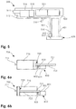
- FIG. 6 a a schematic plan view of a third variant of a device for firing a fluid projectile comprising a fluid container realized by a cylinder and a piston, before use when the fluid container is full;
- FIG. 6 b a schematic plan view according to FIG. 6 a , after use when the fluid container is empty;
- FIG. 7 a a schematic side view of a fourth variant of a device for firing a fluid projectile when the fluid container is full;
- FIG. 7 b a schematic representation according to FIG. 7 a when the fluid container has been emptied and the outlet nozzle is elevated.
- FIG. 8 a schematic side view of a fourth variant of a device for firing a solid projectile.
- FIG. 1 shows a schematic side view of a first variant of a device 100 for firing a fluid projectile with an inserted insert 200 of a first embodiment.
- the device of the first variant (hereinafter “variant 100 ”) comprises a housing 101 with a handle in a lower region.
- the variant 100 has a trigger 110 , which in the present case is formed as a pushbutton.
- a conventional pistol trigger a touchscreen, in particular for example with fingerprint recognition to prevent misuse, or the like may also be formed.
- the variant 100 also comprises on the end face, vertically above the handle, a distance sensor 112 , an outlet nozzle 111 for the fluid and also an LED 113 .
- the variant 100 also comprises an insert 200 with the fluid.
- FIG. 2 shows the variant 100 according to FIG. 1 as a sectional representation.
- the variant 100 also comprises a propulsion drive 114 in the form of a diaphragm pump 114 , which can be controlled by way of a control unit 115 .
- a control unit 115 is also connected to the distance sensor 112 in such a way that distances measured can be processed by the control unit 115 .
- the distance sensor 112 is formed in the present case as an ultrasonic sensor, though other distance sensors, such as for example laser, IR, radar and the like may also be provided.
- the control unit 115 can activate the pump 114 in dependence on the distance measured. In the preferred embodiment, a short distance is fixed by default for safety reasons, so that the pump 114 can only pump with low output, whereby in turn a risk of injury is kept low. If then a distance from a target object that is greater than a limit distance is established by the distance sensor 112 , the output is increased correspondingly by the control unit.
- the variant 100 also comprises two batteries 120 , which according to FIG. 2 lie one behind the other, so that only one battery 120 can be seen. The batteries 120 are connected to the pump 114 by way of power lines 121 , 122 .
- the power lines 121 , 122 also comprise in each case a power connection 123 , 124 for an additional battery pack, which is discussed in more detail below. For a better overview, not all of the lines are depicted in the figures. It is clear to a person skilled in the art how the electronics for these devices should be provided.
- the pump 114 is connected to an insert of the first embodiment 200 by way of an intake tube 116 .
- the intake tube 116 is fixed in the housing 101 and distally comprises a piercing pin 117 .
- the insert 200 comprises a container 201 for the fluid, and also a septum 202 , which can be pierced by the piercing pin 117 .
- the septum 202 is arranged at the foot of the container 201 .
- the insert is held on the housing 101 by way of a locking device that is not shown, in particular a snap spring or the like.
- the insert 200 is formed as a disposable insert. This can be easily pulled out of the housing 101 by overcoming the holding force of the locking device, and a new insert 200 can be pushed in similarly easily, until it snaps into place.
- two batteries in particular two 3-volt batteries (e.g. CR123A), are used to drive the pump 114 . It is consequently possible for only one battery to be used for low output and two batteries to be used for feeding the pump for high output. With the low output and a suitable geometry of the outlet nozzle, a range of about 1.5 m can be achieved; with the high output, i.e. with both batteries, a range of about 5 m can be achieved. At a range of 1.5 m, an eye injury caused by the jet can be ruled out with the greatest probability even at close proximity. When the unit is switched on, in this embodiment the pump is thus operated with one battery.
- two 3-volt batteries e.g. CR123A
- the LED is formed in the present case as a UV-LED.
- a UV-sensitive substance for example uranine, is admixed with the fluid (e.g. the insecticide or in the case of a water pistol the water), so that the fluid is illuminated when it is exposed to UV.
- the fluid e.g. the insecticide or in the case of a water pistol the water
- the fluid e.g. the insecticide or in the case of a water pistol the water
- FIG. 3 shows a schematic side view of a first variant 100 of a device for firing a fluid projectile with an inserted insert 300 of a second embodiment in a sectional representation.
- the elements of the device for firing the fluid projectile are identical to those from FIG. 2 .
- the only difference is in the insert 300 of the second embodiment.
- This insert 300 does not have a container for the fluid here, but comprises additional batteries 310 , 311 , which are connectable to the power connections 123 , 124 of the variant 100 by way of two power connections 304 , 305 . This allows the capacity of the device to be increased significantly.
- the insert 300 also comprises a tube 303 , which is connectable to an external container. When the intake pin 117 pierces the septum 302 of the insert 300 , it protrudes directly into the tube 303 , so that the fluid can be taken in by the pump 114 by way of the tube 303 .
- FIG. 4 shows a schematic representation of an arrangement comprising a first variant 100 of a device for firing a fluid with an inserted insert 300 of a second embodiment and a backpack 400 connected to the insert.
- the tube 303 is connected to a container 401 in the backpack.
- the backpack in the present case comprises shoulder straps 402 , so that it can be carried on the back.
- the container 401 may however also be fastened to a waist belt.
- the tube may also be made sufficiently long that, for example, a single container can be used for a number of devices.
- the insert 300 can be pulled out of the housing 101 similarly easily and replaced for example by an insert 200 .
- FIG. 5 finally shows a schematic side view of a second variant 500 of a device 500 for firing a fluid projectile, formed as a water pistol 500 .
- the water pistol 500 is not restricted to the present form, but may be formed as desired, for example as a water gun, fantasy figures such as a fish spouting water, etc.
- the water pistol 500 in the present case comprises a distance sensor 512 underneath an outlet nozzle 511 , whereby likewise, as in the case of the device described above, a distance can be measured. The distance measured is evaluated by a control unit 515 , whereupon an output for the pump 514 is defined.
- the pump 514 may in the present case be driven by way of two batteries. In FIG. 5 , no electrical lines are depicted to provide a better overview.
- the water pistol 500 comprises within the housing 501 an intake tube 516 , which connects the piercing pin 517 to the pump 514 .
- an insert 600 which comprises a container 601 for water and a septum 602 , has been pushed in.
- the piercing pin 517 pierces the septum, so that water can be transported through the tube 516 to the pump.
- the housing 501 itself may be provided as a water container, the electronics having to be sealed off with respect thereto.
- the housing may in this case simply be provided with a refill opening, which is for example provided with a plug or a screw closure.
- FIG. 6 a shows a schematic plan view (from above) of a third variant of a device for firing a fluid projectile comprising a fluid container realized by a cylinder 710 and a piston 720 , before use and with the fluid container full.
- the present embodiment of a discharge device 700 is consequently constructed in a way similar to a syringe, with a cylinder 710 and a piston 720 that is movable therein and is connected in one piece to a piston rod 721 .
- the piston rod 721 comprises in turn a toothed rack 722 , which is likewise connected in one piece to the piston rod.
- the cylinder 710 comprises a nozzle 711 , through which the fluid can leave as a fluid projectile.
- the piston 720 is movable in the cylinder 710 by way of a drive motor unit 800 .
- a drive motor unit 800 comprises a drive motor 801 with a reduction gear unit 802 , whereby the drive gearwheel 803 of the drive motor unit 800 can be driven.
- the drive gearwheel 803 is in the present case in engagement with the toothed rack 722 of the piston rod 721 , so that, when there is a counterclockwise rotation of the drive gearwheel 803 , the toothed rack 722 , and consequently the piston 720 , is moved into the cylinder 710 , and thereby brings about a discharge of the fluid.
- the drive motor unit 800 may preferably be electronically regulated; in particular, the rotational speed may preferably be regulated substantially independently of the output, whereby the discharge velocity of the fluid is determinable in dependence on the diameters of the nozzle and the cylinder. Furthermore, the device may be controlled in such a way that the discharge takes place during a time period that is predetermined, in particular programmed, or determined by the user.
- FIG. 6 b shows a schematic plan view according to FIG. 6 a , after use when the fluid container is empty.
- the piston 720 has been made to enter the cylinder 710 completely. It can be seen in this case that the toothed rack does not protrude as far as the end of the piston rod 721 opposite from the piston 720 .
- the drive gearwheel 803 disengages from the toothed rack 722 , so that the drive gearwheel 803 idles. This achieves overload protection for the motor in the end position in an easy way.
- FIG. 7 a shows a schematic side view of a third variant of a device 900 for firing a fluid projectile with a full fluid container 1000 .
- plane of the housing is understood hereinafter as meaning a plane that lies substantially in the plane of symmetry of the housing represented, i.e. in the plane of the page of FIGS. 7 a and 7 b .
- FIGS. 7 a and 7 b once again no electrical lines are depicted to provide a better overview.
- the variant 900 in the present case comprises a housing 901 , in which a fluid container 1000 formed as an insert is insertable.
- the housing 901 comprises a peristaltic pump 914 , which is fluidically connected to an intake tube 916 and a nozzle tube 917 .
- the nozzle tube 917 opens out in the nozzle 911 , which in the present case is formed as pivotable about an axis perpendicular to the plane of the housing (see below).
- the housing 901 also comprises a distance sensor 912 , which is arranged underneath the nozzle 911 .
- the data of the distance sensor 912 are sent to a control unit 915 , which is likewise located in the housing 901 and where these data are processed.
- the housing 901 Arranged in the housing 901 is a battery 920 , whereby the peristaltic pump 914 , the distance sensor 912 and the control unit 915 are fed. Finally, the housing 901 comprises a trigger 910 , whereby the function of the device can be initiated, in particular a fluid can be fired.
- the peristaltic pump in the present case lies with an axis of rotation of the motor at right angles to the plane of the housing, for reasons of space it may also lie with the axis of rotation within the plane of the housing.
- the rotor of the peristaltic pump may be fitted over a gear unit of the motor or over the motor itself, so that the portion of tube that is to be pinched during operation is laid around the motor or around the gear unit. A particularly compact form of construction is thereby achieved.
- the nozzle 911 is in the present case pivotable in a plane parallel to a cross-sectional area of the housing 901 . This allows the parabolic flight to be substantially compensated in dependence on the power output of the propulsion drive, that is to say the peristaltic pump 914 , and the distance measured by the distance sensor 912 .
- the nozzle 911 is preferably pivotable automatically by way of a micro servo, but may also be formed as pivotable manually Finally, it is also possible to dispense with the pivotability. In particular, the nozzle may also be fixedly pivoted, so that the parabolic flight is compensated just by the pump output and the distance measured.
- the housing 901 also comprises a receptacle for the fluid container 1000 .
- the fluid container 1000 comprises a cylinder 1010 , which on the end face comprises a Luer lock connection 1011 .
- the counterpart of the Luer lock connection is comprised by the distal end of the intake tube 916 .
- the cylinder 1010 can in this way be mounted by being fitted into the housing 901 and subsequently turned, in particular by an angle of 90°.
- a piston 1020 is movably mounted within the cylinder 1010 .
- a distance from the target object is determined by way of the distance sensor 912 .
- These distance data are sent to the control unit 915 and processed there.
- the necessary power output for the propulsion drive that is to say the peristaltic pump, is then determined.
- the trigger 910 is pressed, the peristaltic pump 914 is put into operation. This makes a negative pressure act on the cylinder 1010 , whereby the fluid located in the cylinder is sucked out of it.
- the piston 1020 moves in the direction of the closed end of the cylinder 1010 .
- the fluid is discharged through the nozzle 911 by way of the nozzle line 917 .
- a balance between the nozzle elevation and the pump output can then be found on the basis of the distance measured, i.e. the output of the pump can be reduced when there is a greater firing angle.
- the cylinder in the present case also comprises an optional pin 1012 , which is in line with the Luer lock connection 1011 and protrudes inwardly, which is discussed in more detail in connection with FIG. 7 b.
- FIG. 7 b shows a schematic representation according to FIG. 7 a when the fluid container 1000 has been emptied and the outlet nozzle 911 is elevated.
- the piston 1020 in the present case comprises an interior space separated off by a diaphragm 1022 and containing a cleaning agent 1021 .
- the diaphragm 1022 is directed toward the pin 1012 . If the fluid store is then emptied, the piston 1020 moves toward the pin 1012 , so that the pin 1012 perforates the diaphragm 1022 .
- the cleaning agent 1021 is then taken in through the pin 1012 , whereby the lines and the nozzle of the device can be cleaned.
- other substances may also be provided, in particular a marking substance or the like.
- a device for firing a projectile is provided, the kinetic energy of the projectile being controlled on the basis of a distance between the device and a target object, in particular being able to be reduced when the distance is small.
- This is of great advantage in particular and water pistols, because in this way it is possible for example to avoid eye injuries during use at a short distance.
- FIG. 8 shows a fourth variant 1100 of a device for firing a solid projectile 1110 .
- the device comprises a gas cartridge 1101 , which in the present case contains CO 2 under pressure.
- the gas cartridge 1101 is exchangeable.
- the gas cartridge 1101 is connected to a valve 1102 , which is controllable by means of the control device 1103 .
- the variant 1100 comprises a barrel 1105 , which is in connection with the valve 1102 and in which gas can be discharged from the gas cartridge 1101 in dependence on the valve position.
- the barrel 1105 there is a solid projectile in the form of a sphere 1110 .
- the variant 1100 further comprises a distance sensor 1104 , which in the present case is formed as an ultrasonic sensor.
- the ultrasonic sensor 1104 is arranged under the barrel 1105 and measures a distance in the longitudinal direction of the barrel.
- the variant 1100 comprises a trigger 1106 .
- the distance from the target object is determined with the distance sensor 1104 by the control unit 1103 and compared with a predetermined limit distance. If the measured distance is less than the predetermined limit distance, the valve 1102 is not actuated, so that the sphere 1110 is not fired. If, however, the measured distance exceeds the predetermined limit distance, the valve 1102 is switched by the control unit 1103 in such a way that a pressure of the gas cartridge 1101 is discharged through the valve 1102 into the barrel 1105 , and so the sphere 1110 is accelerated out of the barrel 1105 .
- sphere 1110 other objects may also be provided, in particular toy projectiles of any kind, such as for example arrows, in particular suction-cup arrows, darts of foam, Styropor, hard rubber, thrown projectiles such as balls, spinning tops, frisbees, clay pigeons, etc.
- arrows in particular suction-cup arrows, darts of foam, Styropor, hard rubber, thrown projectiles such as balls, spinning tops, frisbees, clay pigeons, etc.
- the projectile may also comprise a toy flying object and further objects known to a person skilled in the art.
- the distance may optionally be measured continuously instead of only when the trigger is pulled. This applies to all of the above variants.
Landscapes
- Engineering & Computer Science (AREA)
- General Engineering & Computer Science (AREA)
- Physics & Mathematics (AREA)
- Electromagnetism (AREA)
- Plasma & Fusion (AREA)
- Technology Law (AREA)
- Toys (AREA)
- Containers And Packaging Bodies Having A Special Means To Remove Contents (AREA)
- Infusion, Injection, And Reservoir Apparatuses (AREA)
- Aiming, Guidance, Guns With A Light Source, Armor, Camouflage, And Targets (AREA)
Abstract
Description
Claims (21)
Applications Claiming Priority (4)
| Application Number | Priority Date | Filing Date | Title |
|---|---|---|---|
| CH1709/16 | 2016-12-22 | ||
| CH01709/16 | 2016-12-22 | ||
| CH01709/16A CH713274A2 (en) | 2016-12-22 | 2016-12-22 | Device for firing a projectile. |
| PCT/EP2017/084467 WO2018115481A1 (en) | 2016-12-22 | 2017-12-22 | Spraying device |
Publications (2)
| Publication Number | Publication Date |
|---|---|
| US20190316869A1 US20190316869A1 (en) | 2019-10-17 |
| US10775128B2 true US10775128B2 (en) | 2020-09-15 |
Family
ID=60856891
Family Applications (2)
| Application Number | Title | Priority Date | Filing Date |
|---|---|---|---|
| US16/472,555 Active US10775128B2 (en) | 2016-12-22 | 2017-12-22 | Spraying device |
| US15/852,121 Active US11009312B2 (en) | 2016-12-22 | 2017-12-22 | Spray device |
Family Applications After (1)
| Application Number | Title | Priority Date | Filing Date |
|---|---|---|---|
| US15/852,121 Active US11009312B2 (en) | 2016-12-22 | 2017-12-22 | Spray device |
Country Status (5)
| Country | Link |
|---|---|
| US (2) | US10775128B2 (en) |
| EP (2) | EP3339795B1 (en) |
| CN (2) | CN108225097B (en) |
| CH (1) | CH713274A2 (en) |
| WO (1) | WO2018115481A1 (en) |
Cited By (1)
| Publication number | Priority date | Publication date | Assignee | Title |
|---|---|---|---|---|
| US11892266B1 (en) * | 2022-06-24 | 2024-02-06 | Minjian Mo | Toy electric water pistol |
Families Citing this family (13)
| Publication number | Priority date | Publication date | Assignee | Title |
|---|---|---|---|---|
| AU2018410908B2 (en) * | 2018-03-01 | 2021-11-11 | Axon Enterprise, Inc. | Systems and methods for detecting a distance between a conducted electrical weapon and a target |
| US10835913B2 (en) * | 2018-04-04 | 2020-11-17 | Jens Martin Mispel-Beyer | Refillable vertical foregrip spray device |
| CN110694976A (en) * | 2018-07-09 | 2020-01-17 | 苏州宝时得电动工具有限公司 | High pressure cleaning machine |
| CN108759559A (en) * | 2018-07-20 | 2018-11-06 | 西南交通大学 | A kind of two-stage light gas gun |
| US20200096294A1 (en) * | 2018-09-20 | 2020-03-26 | Jaime L. Givens | Self defense apparatus and method of use |
| DE102019105160A1 (en) * | 2019-02-28 | 2020-09-03 | Carl Hoernecke Chem. Fabrik Gmbh & Co. Kg | Irritant cartridge and irritant spray device |
| DE102019105161A1 (en) * | 2019-02-28 | 2020-09-03 | Carl Hoernecke Chem. Fabrik Gmbh & Co. Kg | Irritant cartridge and irritant spray device |
| CN111114835B (en) * | 2019-12-24 | 2023-06-23 | 兰州空间技术物理研究所 | Liquid propellant supply assembly for electric propulsion and electric propulsion system |
| US11287225B2 (en) * | 2019-12-31 | 2022-03-29 | Dominik Paul Bogacz | Rapid response self-defense device, system and method |
| TWI731709B (en) * | 2020-06-10 | 2021-06-21 | 源美股份有限公司 | Control device of water spray gun |
| CN112169200B (en) * | 2020-09-17 | 2021-12-07 | 湖州凌科智能技术有限公司 | Dead-weight electromagnetic acceleration fire-fighting cleaning penetration fire hook |
| CN114931828B (en) * | 2022-06-16 | 2023-07-25 | 中铁十局集团有限公司 | Open-air raise dust treatment device |
| US11959731B1 (en) * | 2023-02-10 | 2024-04-16 | Deborah S. McLeod | Civilian handheld personal defense and alarm device |
Citations (37)
| Publication number | Priority date | Publication date | Assignee | Title |
|---|---|---|---|---|
| US3374708A (en) * | 1965-01-26 | 1968-03-26 | Eileen T Wall | Electrical anti-personnel weapon |
| US3971292A (en) * | 1974-11-12 | 1976-07-27 | Juan Garcia Paniagua | Projector of fluid with electric charge, of portable type |
| US4704942A (en) * | 1986-08-01 | 1987-11-10 | Barditch Irving F | Charged aerosol |
| US4846044A (en) * | 1988-01-11 | 1989-07-11 | Lahr Roy J | Portable self-defense device |
| US5225623A (en) * | 1990-01-12 | 1993-07-06 | Philip | Self-defense device |
| US5476192A (en) * | 1993-05-27 | 1995-12-19 | Julinot; Helmut | Self-defense device |
| US5503304A (en) * | 1995-03-09 | 1996-04-02 | Keller; John F. | Protective security system |
| US5549220A (en) * | 1994-09-16 | 1996-08-27 | Whalen; Patrick J. | Non-lethal device for self-defense |
| US5656035A (en) * | 1995-04-25 | 1997-08-12 | Avoy; Donald R. | Refillable fibrinogen dispensing kit |
| US5673436A (en) * | 1996-01-11 | 1997-10-07 | Piper; Stan | Defense glove |
| US5787628A (en) * | 1995-10-13 | 1998-08-04 | Teetzel; James W. | Less than lethal apparatus attachment for a firearm |
| US5941629A (en) * | 1994-12-22 | 1999-08-24 | Tuscher; Adolf | Combined flashlight and self-defense spray device |
| US5983548A (en) * | 1998-02-13 | 1999-11-16 | Option Safety, Llc | Non-lethal firearm device |
| US6052051A (en) * | 1999-02-23 | 2000-04-18 | Whalen; Patrick J. | Multilocation defense device |
| US6050454A (en) * | 1998-03-25 | 2000-04-18 | Option Safety, Llc | Non-lethal fluid delivery device |
| WO2000073726A2 (en) | 1999-05-28 | 2000-12-07 | Non-Lethal Defense, Inc. | Non-lethal personal defence device |
| US20020108966A1 (en) * | 2001-02-13 | 2002-08-15 | Park John S. | Personal safety device |
| US6658779B2 (en) * | 1996-04-19 | 2003-12-09 | Eran Nicodemus Bauer | Weapon system comprising a firearm and a non-lethal means for selectively ejecting a stream of fluid |
| US20040077266A1 (en) * | 2002-06-05 | 2004-04-22 | Zimmerman Jeffrey C. | Diaphragm water gun |
| US20040184260A1 (en) * | 2000-10-29 | 2004-09-23 | Kukuk Craig Allen | Multi-functional law enforcement tool |
| CA2463340A1 (en) | 2004-04-06 | 2005-10-06 | Florencio Neto Palma | Virtually powered electro-muscular disruption (vp-emd) |
| US20070086190A1 (en) * | 1999-10-29 | 2007-04-19 | Craig Kukuk | Multi-functional law enforcement tool |
| US20070194048A1 (en) * | 2006-02-22 | 2007-08-23 | Tigerlight, Inc. | Personal defense device |
| USD585520S1 (en) * | 2007-07-26 | 2009-01-27 | Michael Teig | Personal defense device |
| US20090281485A1 (en) * | 2006-11-06 | 2009-11-12 | Aadvark Medical, Llc | Irrigation and aspiration devices and methods |
| US20110198413A1 (en) * | 2008-10-22 | 2011-08-18 | Graco Minnestoa Inc. | Portable airless sprayer |
| KR101157823B1 (en) | 2011-10-25 | 2012-06-22 | 국방과학연구소 | Apparatus for ejecting tear liquid and ejecting system having the same |
| USD681768S1 (en) * | 2011-08-04 | 2013-05-07 | Guardian 8 Corporation | Personal security device |
| USD688769S1 (en) * | 2012-03-27 | 2013-08-27 | Guardian 8 Corporation | Personal security device |
| US8556125B2 (en) * | 2010-02-25 | 2013-10-15 | Charles P Dapper | Portable, non-lethal, self defense device with disabling mechanism |
| US20140252028A1 (en) * | 2013-03-08 | 2014-09-11 | Guardian 8 Corporation | Systems And Methods For Spraying An Aerosol |
| US9022255B1 (en) * | 2014-11-10 | 2015-05-05 | IESW Associates, Trustee for Instant eye-sealing weapon CRT Trust | Instant eye-sealing weapon |
| US9423208B1 (en) * | 2016-01-02 | 2016-08-23 | Alan J. Mahmalji | Vertical foregrip pepper spray device |
| US20170291181A1 (en) * | 2014-09-04 | 2017-10-12 | Victory Innovations Company | Electrostatic Fluid Delivery System |
| US10197358B2 (en) * | 2015-10-06 | 2019-02-05 | Skyler John Hebden | Weapons system foregrip with integrated deployable compartment for compliance device |
| US20190314621A1 (en) * | 2014-02-13 | 2019-10-17 | James Layer | Nasal irrigation assembly and system |
| US10520282B2 (en) * | 2018-03-01 | 2019-12-31 | Ramesh Gupta Nangunoori | Multifunctional personal safety device |
Family Cites Families (27)
| Publication number | Priority date | Publication date | Assignee | Title |
|---|---|---|---|---|
| US4615488A (en) * | 1983-11-18 | 1986-10-07 | Sands Ned R | Toy water gun having three directional nozzles |
| US4750641A (en) * | 1986-09-24 | 1988-06-14 | Chin Fu Hun | Continuous water-ejecting pistol toy with simultaneous sound and red-flash effects |
| US4706848A (en) * | 1986-10-06 | 1987-11-17 | Andrade Bruce M D | High efficiency battery operated water gun |
| US5103366A (en) * | 1988-05-02 | 1992-04-07 | Gregory Battochi | Electrical stun guns and electrically conductive liquids |
| US5230324A (en) * | 1991-10-04 | 1993-07-27 | Horssen Arden D Van | Gas powered weapon having shearable diaphragm member |
| US5244153A (en) * | 1992-06-22 | 1993-09-14 | Kuhn James O | Water gun directional nozzle |
| US5876995A (en) * | 1996-02-06 | 1999-03-02 | Bryan; Bruce | Bioluminescent novelty items |
| US5730325A (en) * | 1996-05-20 | 1998-03-24 | Cheung; David Tat Wai | Toy water gun |
| US6543365B1 (en) * | 1996-11-18 | 2003-04-08 | Jaycor Tactical Systems, Inc. | Non-lethal projectile systems |
| US5893483A (en) * | 1997-01-17 | 1999-04-13 | Duran; Julian Keith | Personal hand-held protection device |
| US5921442A (en) * | 1997-08-21 | 1999-07-13 | Keller; John F. | Manually operated self defense device |
| ITMI20041520A1 (en) * | 2004-07-27 | 2004-10-27 | Beretta Armi Spa | LOW-LETHAL FIREARM AND RELATED METHOD FOR THE SHOOTING OF A LOW-LETHAL BULLET |
| DE102004044237A1 (en) * | 2004-09-14 | 2006-03-30 | Fraunhofer-Gesellschaft zur Förderung der angewandten Forschung e.V. | Method and apparatus of non-lethal exposure to persons |
| US8087968B2 (en) * | 2005-05-23 | 2012-01-03 | Thought Development, Inc. | Device for discharging a stream of fluid in a pattern and method of using same |
| CN2893628Y (en) * | 2006-03-17 | 2007-04-25 | 黄小岳 | Safety defending apparatus |
| US20070289995A1 (en) * | 2006-06-16 | 2007-12-20 | Buzz Bee Toys, Inc. | Steady stream water gun |
| US7956639B2 (en) * | 2008-07-23 | 2011-06-07 | Ndsu Research Foundation | Intelligent cellular electronic structures |
| US8529384B2 (en) * | 2011-02-25 | 2013-09-10 | Shoot The Moon Products Ii, Llc | Marker tag darts, dart guns therefor, and methods |
| KR101259406B1 (en) * | 2011-04-15 | 2013-04-30 | 홍양기 | A perfume bottle for self-protection |
| IL216276A (en) * | 2011-11-10 | 2014-05-28 | Nir Shvalb | Pneumatic launcher and method for launching a projectile at a target |
| US9574854B2 (en) * | 2012-11-08 | 2017-02-21 | Raytheon Company | Directed energy beam power control system and method |
| KR101363131B1 (en) * | 2012-12-14 | 2014-02-14 | 황인철 | Pepper spray can be manufactured in a variety of designs with a portable |
| US9404718B1 (en) * | 2013-01-03 | 2016-08-02 | Vadum Inc. | Multi-shot disrupter apparatus and firing method |
| US9915496B2 (en) * | 2013-03-13 | 2018-03-13 | David Wayne Bergeron | Light gas gun |
| CN204404901U (en) * | 2014-08-25 | 2015-06-17 | 高光宗 | A kind of hydro gun for defending |
| CN204924050U (en) * | 2015-08-09 | 2015-12-30 | 山东海日峰电子科技有限公司 | Multi -functional defence stick |
| US10309753B2 (en) * | 2016-08-17 | 2019-06-04 | Forsythe & Storms Technologies LLC | Portable lachrymatory and electrical device |
-
2016
- 2016-12-22 CH CH01709/16A patent/CH713274A2/en unknown
-
2017
- 2017-12-22 US US16/472,555 patent/US10775128B2/en active Active
- 2017-12-22 US US15/852,121 patent/US11009312B2/en active Active
- 2017-12-22 WO PCT/EP2017/084467 patent/WO2018115481A1/en unknown
- 2017-12-22 CN CN201711415479.5A patent/CN108225097B/en active Active
- 2017-12-22 CN CN201780087149.XA patent/CN110325812B/en active Active
- 2017-12-22 EP EP17210302.0A patent/EP3339795B1/en active Active
- 2017-12-22 EP EP17822321.0A patent/EP3559588B1/en active Active
Patent Citations (38)
| Publication number | Priority date | Publication date | Assignee | Title |
|---|---|---|---|---|
| US3374708A (en) * | 1965-01-26 | 1968-03-26 | Eileen T Wall | Electrical anti-personnel weapon |
| US3971292A (en) * | 1974-11-12 | 1976-07-27 | Juan Garcia Paniagua | Projector of fluid with electric charge, of portable type |
| US4704942A (en) * | 1986-08-01 | 1987-11-10 | Barditch Irving F | Charged aerosol |
| US4846044A (en) * | 1988-01-11 | 1989-07-11 | Lahr Roy J | Portable self-defense device |
| US5225623A (en) * | 1990-01-12 | 1993-07-06 | Philip | Self-defense device |
| US5476192A (en) * | 1993-05-27 | 1995-12-19 | Julinot; Helmut | Self-defense device |
| US5549220A (en) * | 1994-09-16 | 1996-08-27 | Whalen; Patrick J. | Non-lethal device for self-defense |
| US5941629A (en) * | 1994-12-22 | 1999-08-24 | Tuscher; Adolf | Combined flashlight and self-defense spray device |
| US5503304A (en) * | 1995-03-09 | 1996-04-02 | Keller; John F. | Protective security system |
| US5656035A (en) * | 1995-04-25 | 1997-08-12 | Avoy; Donald R. | Refillable fibrinogen dispensing kit |
| US5787628A (en) * | 1995-10-13 | 1998-08-04 | Teetzel; James W. | Less than lethal apparatus attachment for a firearm |
| US5673436A (en) * | 1996-01-11 | 1997-10-07 | Piper; Stan | Defense glove |
| US6658779B2 (en) * | 1996-04-19 | 2003-12-09 | Eran Nicodemus Bauer | Weapon system comprising a firearm and a non-lethal means for selectively ejecting a stream of fluid |
| US5983548A (en) * | 1998-02-13 | 1999-11-16 | Option Safety, Llc | Non-lethal firearm device |
| US6050454A (en) * | 1998-03-25 | 2000-04-18 | Option Safety, Llc | Non-lethal fluid delivery device |
| US6052051A (en) * | 1999-02-23 | 2000-04-18 | Whalen; Patrick J. | Multilocation defense device |
| WO2000073726A2 (en) | 1999-05-28 | 2000-12-07 | Non-Lethal Defense, Inc. | Non-lethal personal defence device |
| US6237461B1 (en) * | 1999-05-28 | 2001-05-29 | Non-Lethal Defense, Inc. | Non-lethal personal defense device |
| US20070086190A1 (en) * | 1999-10-29 | 2007-04-19 | Craig Kukuk | Multi-functional law enforcement tool |
| US20040184260A1 (en) * | 2000-10-29 | 2004-09-23 | Kukuk Craig Allen | Multi-functional law enforcement tool |
| US20020108966A1 (en) * | 2001-02-13 | 2002-08-15 | Park John S. | Personal safety device |
| US20040077266A1 (en) * | 2002-06-05 | 2004-04-22 | Zimmerman Jeffrey C. | Diaphragm water gun |
| CA2463340A1 (en) | 2004-04-06 | 2005-10-06 | Florencio Neto Palma | Virtually powered electro-muscular disruption (vp-emd) |
| US20070194048A1 (en) * | 2006-02-22 | 2007-08-23 | Tigerlight, Inc. | Personal defense device |
| US20090281485A1 (en) * | 2006-11-06 | 2009-11-12 | Aadvark Medical, Llc | Irrigation and aspiration devices and methods |
| USD585520S1 (en) * | 2007-07-26 | 2009-01-27 | Michael Teig | Personal defense device |
| US20110198413A1 (en) * | 2008-10-22 | 2011-08-18 | Graco Minnestoa Inc. | Portable airless sprayer |
| US8556125B2 (en) * | 2010-02-25 | 2013-10-15 | Charles P Dapper | Portable, non-lethal, self defense device with disabling mechanism |
| USD681768S1 (en) * | 2011-08-04 | 2013-05-07 | Guardian 8 Corporation | Personal security device |
| KR101157823B1 (en) | 2011-10-25 | 2012-06-22 | 국방과학연구소 | Apparatus for ejecting tear liquid and ejecting system having the same |
| USD688769S1 (en) * | 2012-03-27 | 2013-08-27 | Guardian 8 Corporation | Personal security device |
| US20140252028A1 (en) * | 2013-03-08 | 2014-09-11 | Guardian 8 Corporation | Systems And Methods For Spraying An Aerosol |
| US20190314621A1 (en) * | 2014-02-13 | 2019-10-17 | James Layer | Nasal irrigation assembly and system |
| US20170291181A1 (en) * | 2014-09-04 | 2017-10-12 | Victory Innovations Company | Electrostatic Fluid Delivery System |
| US9022255B1 (en) * | 2014-11-10 | 2015-05-05 | IESW Associates, Trustee for Instant eye-sealing weapon CRT Trust | Instant eye-sealing weapon |
| US10197358B2 (en) * | 2015-10-06 | 2019-02-05 | Skyler John Hebden | Weapons system foregrip with integrated deployable compartment for compliance device |
| US9423208B1 (en) * | 2016-01-02 | 2016-08-23 | Alan J. Mahmalji | Vertical foregrip pepper spray device |
| US10520282B2 (en) * | 2018-03-01 | 2019-12-31 | Ramesh Gupta Nangunoori | Multifunctional personal safety device |
Cited By (1)
| Publication number | Priority date | Publication date | Assignee | Title |
|---|---|---|---|---|
| US11892266B1 (en) * | 2022-06-24 | 2024-02-06 | Minjian Mo | Toy electric water pistol |
Also Published As
| Publication number | Publication date |
|---|---|
| CN108225097A (en) | 2018-06-29 |
| WO2018115481A1 (en) | 2018-06-28 |
| US11009312B2 (en) | 2021-05-18 |
| EP3559588A1 (en) | 2019-10-30 |
| EP3339795B1 (en) | 2019-07-31 |
| CN110325812A (en) | 2019-10-11 |
| EP3339795A2 (en) | 2018-06-27 |
| US20190316869A1 (en) | 2019-10-17 |
| EP3559588B1 (en) | 2021-06-16 |
| CN108225097B (en) | 2024-02-13 |
| CH713274A2 (en) | 2018-06-29 |
| US20180216909A1 (en) | 2018-08-02 |
| CN110325812B (en) | 2022-04-08 |
| EP3339795A3 (en) | 2018-07-04 |
Similar Documents
| Publication | Publication Date | Title |
|---|---|---|
| US10775128B2 (en) | Spraying device | |
| US9080832B2 (en) | Quick-release valve air gun | |
| US5839422A (en) | Automatic feeder for projectile gun using compressed gas | |
| US20150316345A1 (en) | Quick-Release Valve Air Gun | |
| US6871594B1 (en) | Reusable paint grenade | |
| US7520275B2 (en) | Valve assembly for paintball guns and the like, and improved guns incorporating the assembly | |
| US20110220088A1 (en) | Bug killing gun | |
| US7500434B2 (en) | Ring airfoil style paintball and launcher | |
| US20150308782A1 (en) | Hinged arm safety mechanism for foam dart launcher | |
| WO2006057658A2 (en) | Primer launched projectile systems | |
| US8678877B2 (en) | Marker tag darts, dart guns therefor, and methods | |
| ES2840226T3 (en) | Compact gun to kill insects | |
| US20030089361A1 (en) | Air cannon | |
| CN109313001B (en) | Improved insecticidal gun | |
| US8261665B1 (en) | Fluid-marker delivery systems | |
| US11320233B2 (en) | Non-lethal self-protection system | |
| US5711284A (en) | Paint ball projectile attachment device for bows | |
| US6540107B1 (en) | Self-defense ring | |
| CN211120855U (en) | Lacrimatory agent emitter | |
| AU2007261483A1 (en) | Steady stream water gun | |
| US20240033757A1 (en) | System for atomizing and ejecting liquid for transdermal delivery | |
| WO2024049347A1 (en) | Projectile hopper refillable by removable magazine | |
| JP2012137238A (en) | Gun for squirting scented fluorescent color liquid | |
| TWM259153U (en) | Paint ball pistol with a rotary load mechanism | |
| EP1743136A2 (en) | Primer launched projectile systems |
Legal Events
| Date | Code | Title | Description |
|---|---|---|---|
| FEPP | Fee payment procedure |
Free format text: ENTITY STATUS SET TO UNDISCOUNTED (ORIGINAL EVENT CODE: BIG.); ENTITY STATUS OF PATENT OWNER: LARGE ENTITY |
|
| FEPP | Fee payment procedure |
Free format text: ENTITY STATUS SET TO SMALL (ORIGINAL EVENT CODE: SMAL); ENTITY STATUS OF PATENT OWNER: LARGE ENTITY |
|
| STPP | Information on status: patent application and granting procedure in general |
Free format text: DOCKETED NEW CASE - READY FOR EXAMINATION |
|
| STPP | Information on status: patent application and granting procedure in general |
Free format text: NON FINAL ACTION MAILED |
|
| AS | Assignment |
Owner name: PIEXON AG, SWITZERLAND Free format text: ASSIGNMENT OF ASSIGNORS INTEREST;ASSIGNOR:THOMANN, JUERG;REEL/FRAME:051897/0598 Effective date: 20191205 |
|
| STPP | Information on status: patent application and granting procedure in general |
Free format text: RESPONSE TO NON-FINAL OFFICE ACTION ENTERED AND FORWARDED TO EXAMINER |
|
| STPP | Information on status: patent application and granting procedure in general |
Free format text: NOTICE OF ALLOWANCE MAILED -- APPLICATION RECEIVED IN OFFICE OF PUBLICATIONS |
|
| FEPP | Fee payment procedure |
Free format text: ENTITY STATUS SET TO UNDISCOUNTED (ORIGINAL EVENT CODE: BIG.); ENTITY STATUS OF PATENT OWNER: LARGE ENTITY |
|
| STCF | Information on status: patent grant |
Free format text: PATENTED CASE |
|
| FEPP | Fee payment procedure |
Free format text: ENTITY STATUS SET TO SMALL (ORIGINAL EVENT CODE: SMAL); ENTITY STATUS OF PATENT OWNER: SMALL ENTITY |
|
| MAFP | Maintenance fee payment |
Free format text: PAYMENT OF MAINTENANCE FEE, 4TH YR, SMALL ENTITY (ORIGINAL EVENT CODE: M2551); ENTITY STATUS OF PATENT OWNER: SMALL ENTITY Year of fee payment: 4 |