US10772202B2 - Flat data transmission cable - Google Patents

Flat data transmission cable Download PDF

Info

Publication number
US10772202B2
US10772202B2 US16/408,354 US201916408354A US10772202B2 US 10772202 B2 US10772202 B2 US 10772202B2 US 201916408354 A US201916408354 A US 201916408354A US 10772202 B2 US10772202 B2 US 10772202B2
Authority
US
United States
Prior art keywords
data transmission
transmission cable
layer
wires
bending
Prior art date
Legal status (The legal status is an assumption and is not a legal conclusion. Google has not performed a legal analysis and makes no representation as to the accuracy of the status listed.)
Active
Application number
US16/408,354
Other versions
US20190371493A1 (en
Inventor
Mindi Ni
Yichang Chen
Current Assignee (The listed assignees may be inaccurate. Google has not performed a legal analysis and makes no representation or warranty as to the accuracy of the list.)
Alltop Electronics Suzhou Co Ltd
Original Assignee
Alltop Electronics Suzhou Co Ltd
Priority date (The priority date is an assumption and is not a legal conclusion. Google has not performed a legal analysis and makes no representation as to the accuracy of the date listed.)
Filing date
Publication date
Application filed by Alltop Electronics Suzhou Co Ltd filed Critical Alltop Electronics Suzhou Co Ltd
Assigned to ALLTOP ELECTRONICS (SUZHOU) LTD. reassignment ALLTOP ELECTRONICS (SUZHOU) LTD. ASSIGNMENT OF ASSIGNORS INTEREST (SEE DOCUMENT FOR DETAILS). Assignors: CHEN, Yichang, NI, Mindi
Publication of US20190371493A1 publication Critical patent/US20190371493A1/en
Application granted granted Critical
Publication of US10772202B2 publication Critical patent/US10772202B2/en
Active legal-status Critical Current
Anticipated expiration legal-status Critical

Links

Images

Classifications

    • HELECTRICITY
    • H05ELECTRIC TECHNIQUES NOT OTHERWISE PROVIDED FOR
    • H05KPRINTED CIRCUITS; CASINGS OR CONSTRUCTIONAL DETAILS OF ELECTRIC APPARATUS; MANUFACTURE OF ASSEMBLAGES OF ELECTRICAL COMPONENTS
    • H05K1/00Printed circuits
    • H05K1/02Details
    • H05K1/11Printed elements for providing electric connections to or between printed circuits
    • H05K1/111Pads for surface mounting, e.g. lay-out
    • HELECTRICITY
    • H01ELECTRIC ELEMENTS
    • H01BCABLES; CONDUCTORS; INSULATORS; SELECTION OF MATERIALS FOR THEIR CONDUCTIVE, INSULATING OR DIELECTRIC PROPERTIES
    • H01B11/00Communication cables or conductors
    • HELECTRICITY
    • H01ELECTRIC ELEMENTS
    • H01BCABLES; CONDUCTORS; INSULATORS; SELECTION OF MATERIALS FOR THEIR CONDUCTIVE, INSULATING OR DIELECTRIC PROPERTIES
    • H01B11/00Communication cables or conductors
    • H01B11/18Coaxial cables; Analogous cables having more than one inner conductor within a common outer conductor
    • H01B11/20Cables having a multiplicity of coaxial lines
    • H01B11/203Cables having a multiplicity of coaxial lines forming a flat arrangement
    • HELECTRICITY
    • H01ELECTRIC ELEMENTS
    • H01BCABLES; CONDUCTORS; INSULATORS; SELECTION OF MATERIALS FOR THEIR CONDUCTIVE, INSULATING OR DIELECTRIC PROPERTIES
    • H01B7/00Insulated conductors or cables characterised by their form
    • H01B7/0054Cables with incorporated electric resistances
    • HELECTRICITY
    • H01ELECTRIC ELEMENTS
    • H01BCABLES; CONDUCTORS; INSULATORS; SELECTION OF MATERIALS FOR THEIR CONDUCTIVE, INSULATING OR DIELECTRIC PROPERTIES
    • H01B7/00Insulated conductors or cables characterised by their form
    • H01B7/02Disposition of insulation
    • HELECTRICITY
    • H01ELECTRIC ELEMENTS
    • H01BCABLES; CONDUCTORS; INSULATORS; SELECTION OF MATERIALS FOR THEIR CONDUCTIVE, INSULATING OR DIELECTRIC PROPERTIES
    • H01B7/00Insulated conductors or cables characterised by their form
    • H01B7/02Disposition of insulation
    • H01B7/0208Cables with several layers of insulating material
    • H01B7/0225Three or more layers
    • HELECTRICITY
    • H01ELECTRIC ELEMENTS
    • H01BCABLES; CONDUCTORS; INSULATORS; SELECTION OF MATERIALS FOR THEIR CONDUCTIVE, INSULATING OR DIELECTRIC PROPERTIES
    • H01B7/00Insulated conductors or cables characterised by their form
    • H01B7/02Disposition of insulation
    • H01B7/0241Disposition of insulation comprising one or more helical wrapped layers of insulation
    • HELECTRICITY
    • H01ELECTRIC ELEMENTS
    • H01BCABLES; CONDUCTORS; INSULATORS; SELECTION OF MATERIALS FOR THEIR CONDUCTIVE, INSULATING OR DIELECTRIC PROPERTIES
    • H01B7/00Insulated conductors or cables characterised by their form
    • H01B7/04Flexible cables, conductors, or cords, e.g. trailing cables
    • HELECTRICITY
    • H01ELECTRIC ELEMENTS
    • H01BCABLES; CONDUCTORS; INSULATORS; SELECTION OF MATERIALS FOR THEIR CONDUCTIVE, INSULATING OR DIELECTRIC PROPERTIES
    • H01B7/00Insulated conductors or cables characterised by their form
    • H01B7/08Flat or ribbon cables
    • H01B7/0853Juxtaposed parallel wires, fixed to each other without a support layer
    • HELECTRICITY
    • H01ELECTRIC ELEMENTS
    • H01BCABLES; CONDUCTORS; INSULATORS; SELECTION OF MATERIALS FOR THEIR CONDUCTIVE, INSULATING OR DIELECTRIC PROPERTIES
    • H01B7/00Insulated conductors or cables characterised by their form
    • H01B7/17Protection against damage caused by external factors, e.g. sheaths or armouring
    • H01B7/18Protection against damage caused by wear, mechanical force or pressure; Sheaths; Armouring
    • H01B7/20Metal tubes, e.g. lead sheaths
    • H01B7/205Metal tubes, e.g. lead sheaths composed of aluminium
    • HELECTRICITY
    • H01ELECTRIC ELEMENTS
    • H01BCABLES; CONDUCTORS; INSULATORS; SELECTION OF MATERIALS FOR THEIR CONDUCTIVE, INSULATING OR DIELECTRIC PROPERTIES
    • H01B7/00Insulated conductors or cables characterised by their form
    • H01B7/17Protection against damage caused by external factors, e.g. sheaths or armouring
    • H01B7/18Protection against damage caused by wear, mechanical force or pressure; Sheaths; Armouring
    • H01B7/22Metal wires or tapes, e.g. made of steel
    • H01B7/226Helicoidally wound metal wires or tapes
    • HELECTRICITY
    • H01ELECTRIC ELEMENTS
    • H01BCABLES; CONDUCTORS; INSULATORS; SELECTION OF MATERIALS FOR THEIR CONDUCTIVE, INSULATING OR DIELECTRIC PROPERTIES
    • H01B7/00Insulated conductors or cables characterised by their form
    • H01B7/17Protection against damage caused by external factors, e.g. sheaths or armouring
    • H01B7/18Protection against damage caused by wear, mechanical force or pressure; Sheaths; Armouring
    • H01B7/22Metal wires or tapes, e.g. made of steel
    • H01B7/228Metal braid
    • HELECTRICITY
    • H01ELECTRIC ELEMENTS
    • H01BCABLES; CONDUCTORS; INSULATORS; SELECTION OF MATERIALS FOR THEIR CONDUCTIVE, INSULATING OR DIELECTRIC PROPERTIES
    • H01B7/00Insulated conductors or cables characterised by their form
    • H01B7/17Protection against damage caused by external factors, e.g. sheaths or armouring
    • H01B7/29Protection against damage caused by extremes of temperature or by flame
    • H01B7/295Protection against damage caused by extremes of temperature or by flame using material resistant to flame
    • HELECTRICITY
    • H01ELECTRIC ELEMENTS
    • H01RELECTRICALLY-CONDUCTIVE CONNECTIONS; STRUCTURAL ASSOCIATIONS OF A PLURALITY OF MUTUALLY-INSULATED ELECTRICAL CONNECTING ELEMENTS; COUPLING DEVICES; CURRENT COLLECTORS
    • H01R12/00Structural associations of a plurality of mutually-insulated electrical connecting elements, specially adapted for printed circuits, e.g. printed circuit boards [PCB], flat or ribbon cables, or like generally planar structures, e.g. terminal strips, terminal blocks; Coupling devices specially adapted for printed circuits, flat or ribbon cables, or like generally planar structures; Terminals specially adapted for contact with, or insertion into, printed circuits, flat or ribbon cables, or like generally planar structures
    • H01R12/50Fixed connections
    • H01R12/51Fixed connections for rigid printed circuits or like structures
    • H01R12/53Fixed connections for rigid printed circuits or like structures connecting to cables except for flat or ribbon cables
    • HELECTRICITY
    • H01ELECTRIC ELEMENTS
    • H01BCABLES; CONDUCTORS; INSULATORS; SELECTION OF MATERIALS FOR THEIR CONDUCTIVE, INSULATING OR DIELECTRIC PROPERTIES
    • H01B7/00Insulated conductors or cables characterised by their form
    • H01B7/08Flat or ribbon cables
    • H01B7/0823Parallel wires, incorporated in a flat insulating profile
    • HELECTRICITY
    • H01ELECTRIC ELEMENTS
    • H01BCABLES; CONDUCTORS; INSULATORS; SELECTION OF MATERIALS FOR THEIR CONDUCTIVE, INSULATING OR DIELECTRIC PROPERTIES
    • H01B7/00Insulated conductors or cables characterised by their form
    • H01B7/08Flat or ribbon cables
    • H01B7/0861Flat or ribbon cables comprising one or more screens
    • HELECTRICITY
    • H05ELECTRIC TECHNIQUES NOT OTHERWISE PROVIDED FOR
    • H05KPRINTED CIRCUITS; CASINGS OR CONSTRUCTIONAL DETAILS OF ELECTRIC APPARATUS; MANUFACTURE OF ASSEMBLAGES OF ELECTRICAL COMPONENTS
    • H05K1/00Printed circuits
    • H05K1/02Details
    • H05K1/11Printed elements for providing electric connections to or between printed circuits
    • H05K1/117Pads along the edge of rigid circuit boards, e.g. for pluggable connectors
    • HELECTRICITY
    • H05ELECTRIC TECHNIQUES NOT OTHERWISE PROVIDED FOR
    • H05KPRINTED CIRCUITS; CASINGS OR CONSTRUCTIONAL DETAILS OF ELECTRIC APPARATUS; MANUFACTURE OF ASSEMBLAGES OF ELECTRICAL COMPONENTS
    • H05K2201/00Indexing scheme relating to printed circuits covered by H05K1/00
    • H05K2201/09Shape and layout
    • H05K2201/09009Substrate related
    • H05K2201/09027Non-rectangular flat PCB, e.g. circular
    • HELECTRICITY
    • H05ELECTRIC TECHNIQUES NOT OTHERWISE PROVIDED FOR
    • H05KPRINTED CIRCUITS; CASINGS OR CONSTRUCTIONAL DETAILS OF ELECTRIC APPARATUS; MANUFACTURE OF ASSEMBLAGES OF ELECTRICAL COMPONENTS
    • H05K2201/00Indexing scheme relating to printed circuits covered by H05K1/00
    • H05K2201/09Shape and layout
    • H05K2201/09209Shape and layout details of conductors
    • H05K2201/09372Pads and lands
    • H05K2201/094Array of pads or lands differing from one another, e.g. in size, pitch, thickness; Using different connections on the pads
    • HELECTRICITY
    • H05ELECTRIC TECHNIQUES NOT OTHERWISE PROVIDED FOR
    • H05KPRINTED CIRCUITS; CASINGS OR CONSTRUCTIONAL DETAILS OF ELECTRIC APPARATUS; MANUFACTURE OF ASSEMBLAGES OF ELECTRICAL COMPONENTS
    • H05K2201/00Indexing scheme relating to printed circuits covered by H05K1/00
    • H05K2201/10Details of components or other objects attached to or integrated in a printed circuit board
    • H05K2201/10227Other objects, e.g. metallic pieces
    • H05K2201/10356Cables

Definitions

  • the present disclosure relates to a data transmission cable, and more particularly to a flat data transmission cable having better high frequency performance.
  • a transmission cable can be used as a medium for an electrical connection between two electronic devices and can carry out the expected signal transmission stably. Therefore, the transmission cable is widely used in various electronic devices.
  • transmission cables connected with USB, HDMI, DVI, Displayport and other types of connector has a performance of higher transmission rate, longer transmission distance and higher quality, and is popular with consumers.
  • the transmission cable usually has a plurality of metallic wires, and each metallic wire is usually fixed to a metallic layer by an outer mylar layer. Usually, in most terminal equipments, the transmission cable needs to be bent to facilitate the connection of two electronic devices at different locations.
  • the present invention includes a data transmission cable comprising a plurality of juxtaposed wires, a plastic layer enclosing on the wires integrally and a metallic layer formed by a metal material belt arranged on an outer side of the plastic layer in a spiral winding way.
  • the data transmission cable In the length direction of the data transmission cable, the data transmission cable has at least one bending portion, the data transmission cable is formed with a first section and a second section on both sides of the bending portion, and a stable bending angle is formed between the first section and the second section.
  • FIG. 1 is a perspective view of a data transmission cable before bending in accordance with a first embodiment of the present disclosure, showing a state of a metallic layer spiral winding thereon;
  • FIG. 2 is a top view of the data transmission cable shown in FIG. 1 ;
  • FIG. 3 a and FIG. 3 b are side views of a partial structure of the data transmission cable shown in FIG. 1 , and showing a comparison of the data transmission cable bending at a predetermined angle with bending at a practical angle;
  • FIG. 4 is a front view of the data transmission cable shown in FIG. 3 b;
  • FIG. 5 is an enlarged schematic view of a front end surface of the data transmission cable shown in FIG. 4 , for showing the configuration of the data transmission cable distinctly;
  • FIG. 6 a is an impedance change diagram of a traditional data transmission cable after bending
  • FIG. 6 b is an impedance change diagram of the data transmission cable shown in FIG. 3 b;
  • FIG. 7 is an insertion loss diagram of the data transmission cable shown in FIG. 3 b as bending and revoking bending;
  • FIG. 8 is a front view of a data transmission cable in accordance with a second embodiment of the present disclosure.
  • FIG. 9 is a perspective view of a data transmission cable before bending in accordance with a third embodiment of the present disclosure, showing a state of a metallic layer and a mylar layer spiral winding thereon.
  • the present disclosure relates to a flat data transmission cable, and the data transmission cable comprises at least a plurality of juxtaposed wires and a plastic layer enclosing on the wires integrally, a detailed illustration of several preferred embodiments is as follow.
  • a first embodiment of the present disclosure discloses a data transmission cable 100 , a state diagram of the data transmission cable 100 before bending is shown in FIGS. 1 to 2 , and an actual state diagram of the data transmission cable 100 after bending is shown in FIGS. 4 to 5 .
  • the data transmission cable 100 comprises a plurality of juxtaposed wires 1 , a plastic layer 2 enclosing on the wires 1 integrally and a metallic layer 3 formed by a metal material belt arranged on an outer side of the plastic layer 2 in a spiral winding way.
  • each wire 1 has a conductor 11 and an insulative cladding layer 12 enclosing on the conductor 11 .
  • Central axes of the conductors 11 are located on a same plane, the plastic layer 2 is enclosing on the cladding layers 12 to form a common single insulation layer.
  • the plastic layer 2 defines a top surface and a bottom surface parallel to the plane in which the central axes of the conductors 11 located.
  • the arrangement of the conductors 11 can be effectively maintained for preventing distortion or folding.
  • the winding arrangement of the metallic layer 3 can be further facilitated for avoiding air interlayer between the plastic layer 2 and the metallic layer 3 .
  • the conductors 11 can be well protected by the cladding layer 12 , thereby preventing short circuit caused by two adjacent conductors 11 contacting during the forming process of the plastic layer 2 .
  • the thickness of the plastic layer 2 can also be set as light as possible when the wire 1 having the cladding layer 12 , just making sure that the relative position of all wires 1 , and then the thickness of the whole data transmission cable 100 can be reduced, thus the whole of data transmission cable 100 can be made much thinner and much softer.
  • the cladding layer 12 is made of same or similar material as the plastic layer 2 , and preferably made of same kind material, thus when the data transmission cable 100 in the present invention is molded, the combination of the plastic layer 2 and the cladding layer 12 is better, and a good fusion can be achieved with minimizing the stratification problem or air entry, thus the forming effect is better.
  • the same kind material is a polyhydrocarbon compound, and further, the polyhydrocarbon compound is preferably a high density polyethylene.
  • the plastic layer 2 and the cladding layer 12 can be preferably made of plastic material with a dielectric coefficient close to air, therefore the impedance of the cladding layer 12 and the plastic layer 2 can be reduced, and a better signal transmission environment can be provided for the conductors 11 , the propagation delay of signals and crosstalk between signals can be reduced to ensure high-speed and effective transmission of signals and reduce signal attenuation.
  • the distance between the outer edge of the conductor 11 and the outer edge of the plastic layer 2 is in the range of 0.1 mm to 0.45 mm, and preferably in the range of 0.15 mm to 0.25 mm.
  • the above distance is also the distance between the conductor 11 and metallic layer 3 , and one of the factors affecting the stable signal transmission of the wire 1 , especially the high frequency data transmission. As the distance is smaller, the impedance is smaller and the high frequency performance is better.
  • the thickness of the whole data transmission cable 100 is smaller, and the data transmission cable 100 can be softer and thinner.
  • the metallic layer 3 will affect signal transmission of the conductors 11 , and the above-mentioned interval of the invention can better meet various requirements.
  • each wire 1 also can have only the conductor 11 without the cladding layer 12 , that is, the plastic layer 2 is directly enclosing on the wires 1 , and the same effect can be achieved.
  • the thickness of the plastic layer 2 can be further reduced, and the overall thickness of the data transmission cable 100 can be further reduced.
  • the wires 1 are disposed in an equally spaced arrangement in present embodiment, and in the arrangement direction of the wires 1 , the number of the wires 1 is in the range of 3 to 50.
  • the wires 1 define at least two grounding wires and at least a signal wire between the two grounding wires. Therefore, the interference around the signal wire can be eliminated by grounding wire, and the signal transmission environment of the signal wire can be guaranteed, thereby improving the efficiency and stability of signal transmission.
  • the number of the signal wires between two adjacent ground wires is preferably two.
  • the two signal wires constitute a signal wire group for transmitting differential signals, that is to say, the grounding wire is used for protecting the signal wire group to ensure the high frequency transmission performance.
  • the wires 1 only comprise a plurality of grounding wires g and several signal wire groups s, and the number of grounding wires g is one more than that of the signal wire groups s.
  • the two wires 1 on both sides are grounding wires g, and one signal wire group s is arranged between every two neighboring grounding wires g.
  • each signal wire group can be protected by two neighboring grounding wires on both sides thereof, and the high frequency transmission characteristics of the whole data transmission cable 100 can be further improved.
  • the signal wires in order to correspond with other single-ended signal transmission, also define at least one single-ended signal wire.
  • the number of the signal wires is twice as that of the grounding wires, to accommodate Mini SAS (Mini Serial Attached Small Computer System Interface) standard, and in the arrangement direction of the wires 1 , two single-ended signal wires are defined on outer sides of the grounding pads, that is to say, two single-ended signal wires are located on both sides of the entire data transmission cable 100 , the grounding wires and the signal wire groups are arranged between the two single-ended signal wires in proper sequence.
  • the data transmission cable 100 also can be provided with a plurality of grounding wires and a plurality of single-ended signal wires.
  • a plurality of grounding wires is one more than that of the single-ended signal wires, to accommodate narrow version of Mini SAS standard.
  • the specific arrangement is as follows: the two wires 1 on both sides are grounding wires to shield the whole data transmission cable 100 from both sides thereof, and in the arrangement direction of the wires 1 , the grounding wires and the signal wires are arranged alternately.
  • all the conductors 11 of the wires 1 have a same outer diameter, and the ratio of the center distance between every two neighboring wires 1 to the outer diameter of the conductor 11 is preferably in the range of 1.4 to 2.8.
  • the wires 1 define a plurality of differential signal wire groups, according to the setting of the plastic layer 2 and the metallic layer 3 , when the ratio of the center distance between two adjacent wires 1 in each differential signal wire group to the outer diameter of the conductor 11 is in the range of 1.4 to 2.8, the differential impedance of the differential signal wire group is in the range of 79 to 106 Ohm.
  • the differential impedance of the wires 1 in each signal wire group can be controlled in the range of 79 to 91 Ohm.
  • the conductor 11 has an outer diameter (traditionally expressed in AWG size) in the range of 31 to 33 American Wire Gauge (AWG), at this time, the center distance between two neighboring wires 1 in each signal wire group is defined in the range of 0.28 mm to 0.52 mm, to ensure the differential impedance of the wires 1 in each signal wire group in the range of 79 to 91 Ohm.
  • AWG American Wire Gauge
  • the center distance between two neighboring wires 1 in each signal wire group is defined in the range of 0.44 mm to 0.52 mm, to guarantee the differential impedance of the wires 1 in each signal wire group in the range of 79 to 91 Ohm.
  • the center distance between two neighboring wires 1 is 0.48 mm, the differential impedance of the wires 1 in each signal wire group can be controlled with 85 Ohm.
  • the center distance between two neighboring wires 1 in each signal wire group is defined in the range of 0.36 mm to 0.44 mm, to guarantee the differential impedance of the wires 1 in each signal wire group in the range of 79 to 91 Ohm.
  • the differential impedance of the wires 1 in each signal wire group can be controlled with 85 Ohm.
  • the center distance between two neighboring wires 1 in each signal wire group is defined in the range of 0.28 mm to 0.36 mm, to guarantee the differential impedance of the wires 1 in each signal wire group in the range of 79 to 91 Ohm.
  • the differential impedance of the wires 1 in each signal wire group can be controlled with 85 Ohm.
  • the differential impedance of the wires 1 in each signal wire group can be controlled in the range of 94 to 106 Ohm.
  • the conductor 11 to ensure the softness and lightness of the data transmission cable 100 , the conductor 11 , the outer diameter of the conductor 11 is 33 AWG or 34 AWG, the center distance between two neighboring wires 1 in each signal wire group is defined in the range of 0.35 mm to 0.51 mm, to guarantee the differential impedance of the wires 1 in each signal wire group in the range of 94 to 106 Ohm.
  • the center distance between two neighboring wires 1 in each signal wire group is defined in the range of 0.43 mm to 0.51 mm, to guarantee the differential impedance of the wires 1 in each signal wire group in the range of 94 to 106 Ohm.
  • the differential impedance of the wires 1 in each signal wire group can be controlled with 100 Ohm.
  • the center distance between two neighboring wires 1 in each signal wire group is defined in the range of 0.35 mm to 0.43 mm, to guarantee the differential impedance of the wires 1 in each signal wire group in the range of 94 to 106 Ohm.
  • the differential impedance of the wires 1 in each signal wire group can be controlled with 100 Ohm.
  • each wire 1 has the conductor 11 and the insulative cladding layer 12 , and center distance between every two neighboring wires 1 is equal to the outer diameter of the wire 1 , that is to say every two neighboring wires 1 are abutting each other, thus it's convenient for forming the data transmission cable 100 .
  • the plastic layer 2 is enclosing on the wires 1 integrally
  • the metallic layer 3 is formed by a metal belt arranged on an outer side of the plastic layer 2 in a spiral winding way, therefore compact winding and bonding between the metallic layer 3 and the plastic layer 2 can be realized, and an intimate enclosing is formed by the metallic layer 3 , on the premise of the data transmission cable 100 having the metallic layer 3 shielding interference, the data transmission cable 100 can be made more thinner and softer, and the overall thickness of the data transmission cable 100 can be controlled in the range of 0.3 mm to 1 mm.
  • each wire 1 can or cannot have the cladding layer 12 .
  • the overall thickness d 2 of the wire 1 and the plastic layer 2 can be controlled in the range of 0.25 mm to 0.8 mm
  • the overall thickness d 2 of the wire 1 and the plastic layer 2 can be controlled in the range of 0.3 mm to 0.6 mm.
  • the wire 1 defines the cladding layer 12 with a thickness of 0.1 mm, and the thickness of the plastic layer 2 is 0.07 mm, thus the overall thickness d 2 of the wire 1 and the plastic layer 2 can be controlled with 0.54 mm
  • the thickness of the cladding layer 12 and the plastic layer 2 can be adjusted according to actual needs and technical capabilities, and specific settings is not restricted to the conductor 11 with 32 AWG.
  • the metallic layer 3 has at least an aluminum foil layer 31 and a bonding layer 32 arranged on the side of the aluminum foil layer 31 facing to the plastic layer 2 , thus the metallic layer 3 is bonded to the outer side of the plastic layer 2 by the bonding layer 32 .
  • the metallic layer 3 also has fire protection function, which can make the data transmission cable 100 reach horizontal flame retardant grade of FT-2 rating and vertical flame retardant grade of VW-1 rating.
  • the metallic layer 3 is arranged on an outer side of the plastic layer 2 in a spiral winding way, thus tight winding and bonding between the metallic layer 3 and the plastic layer 2 can be realized.
  • the overall volume of the data transmission cable 100 is reduced as much as possible.
  • the bonding layer 32 is arranged on the side of the metallic layer 3 facing to the plastic layer 2 , the metallic layer 3 can not only be fixed on the outer side of the plastic layer 2 directly by bonding without a mylar layer, thus the whole of data transmission cable 100 can be made much thinner and much softer.
  • the data transmission cable 100 can be made more softer and more lightweight with a high frequency transmission performance.
  • the bonding layer 32 is connecting the plastic layer 2 and the aluminum foil layer 31 by hot melting, to facilitate the setting of the bonding layer 32 and the winding of the metallic layer 3 , at the same time, the bonding strength and closeness of the metallic layer 3 and the plastic layer 2 can be increased.
  • the metallic layer 3 further has an insulating layer 36 arranged on the side of the aluminum foil layer 31 deviating from the plastic layer 2 , the insulating layer 36 can replace the mylar layer in the prior art, insulate the outside and protect the aluminum foil layer 31 at the same time.
  • the metallic layer 3 can or cannot have the insulating layer, the whole thickness d 1 of the metallic layer 3 is defined in the range of 0.010 mm to 0.055 mm, to minimize the thickness of the data transmission cable 100 on the basis of realizing external shielding.
  • the whole thickness d 1 of the metallic layer 3 is defined in the range of 0.015 mm to 0.025 mm.
  • the thickness of the data transmission cable 100 can be controlled in the range of 0.35 mm to 0.65 mm.
  • the outer diameter of the conductor 11 is 32 AWG
  • the overall thickness d 2 of the wire 1 and the plastic layer 2 is about 0.54 mm
  • the thickness of the metallic layer 3 is 0.045 mm
  • the thickness of the data transmission cable 100 can be of 0.63 mm
  • the thickness of the cladding layer 12 , the plastic layer 2 and the metallic layer 3 can be adjusted according to actual needs and technical capabilities, and specific settings is not restricted to above embodiments.
  • the metal belt in a spiral winding way of present invention can be designed as:
  • the width of the metal belt is set as W, in a length direction of the data transmission cable 100 , the metal belt is wound with N rings, the data transmission cable 100 has a length L, and the requirement of L ⁇ N*W should be satisfied.
  • winding setting besides the data transmission cable 100 can be guaranteed with a compact structure and for minimizing the size thereof as much as possible, and have a fire-proof property. And the impedance discontinuity caused by bending can be effectively reduced, thereby ensuring the stability of signal transmission, especially high frequency signal transmission.
  • an overlapping coating area 35 is formed between every two adjacent rings of the metal belt, and the overlapping coating area 35 has a width w along the width direction of the metal belt, the proportion of the width w of the overlapping coating area 35 occupying the width W of the metal belt is 5% to 50%.
  • the width w of the overlapping coating area 35 is at least 0.5 mm, preferably not less than 0.8 mm and optimally 1 mm, thus, the winding continuity of the metallic layer 3 can be effectively guaranteed.
  • the winding angle of the metal belt relative to the width direction of the data transmission cable 100 is in the range of 40° to 55°, and preferably 45° to 53°. With the above setting, the flexibility of the data transmission cable 100 in the length direction thereof is more uniform, and it is not easy to cause cracks when bending.
  • the width W of the metal belt is defined not less than half of the whole width of the data transmission cable 100 , preferably not less than 0.75 times of the whole width of the data transmission cable 100 , optimally not less than one times of the whole width of the data transmission cable 100 .
  • the winding of the metal belt is more convenient and the compactness of the winding can be controlled conveniently, and at the same time, the softness of the entire data transmission cable 100 after winding can be guaranteed.
  • the overlapping area of the entire data transmission cable 100 at per unit length can be less, thereby further reducing the possibility of the metal belt spreading when bending.
  • the whole width of the data transmission cable 100 is defined in the range of d 0 *n to d 0 *(n+2).
  • the ratio of the whole width of the data transmission cable 100 to n is 1 to 1.25 times of the width, thus it ensures that the plastic layer 2 with a certain width still can be defined on both outer sides of wires 1 in the width direction of the data transmission cable 100 , but the plastic layer 2 on both sides of the data transmission cable 100 in the width direction will not be too large to increase the whole width of the data transmission cable 100 , thus an effective protection for the wires 1 can be realized as the plastic layer 2 having a minimal size.
  • the weight of per centimeter as a unit length of the data transmission cable 100 is in the range of 0.015 g to 0.30 g. Moreover, in the case of per centimeter as a unit length, the ratio of the weight of the data transmission cable 100 to the number of wires 1 is in the range of 0.0080 to 0.0020. Therefore, the data transmission cable 100 is not only flexible with higher frequency stability, but also more portable.
  • FIG. 9 illustrates a data transmission cable 100 ′ according to a third embodiment of the present invention before bending, the status of the data transmission cable 100 ′ after bending is shown in FIG. 3 a to FIG. 5 , compared with the first embodiment described above, the data transmission cable 100 ′ further includes a mylar layer 4 coated on the outside of the metallic layer 3 ′.
  • the metallic layer 3 ′ can only have the aluminum foil layer, also can have the aluminum foil layer and the bonding layer same as the first embodiment, and further can have the insulating layer, thus, an encapsulation compaction effect of the metallic layer 3 ′ can be guaranteed further by the mylar layer 4 .
  • the mylar layer 4 is also defined in a spiral winding way, and adhesive glue is arranged on the side of the mylar layer 4 facing the metallic layer 3 ′.
  • the mylar layer 4 is fixed to the outer side of the metallic layer 3 ′ by the adhesive glue after hot melting, thereby ensuring the coating effect of the mylar layer 4 as compact as that of the metallic layer 3 ′.
  • the mylar layer 4 and the metallic layer 3 ′ are defined in a cross-winding way, to guarantee the winding of the metallic layer 3 ′, and further reduce or avoid the phenomenon of impedance discontinuity, for guaranteeing the stability of signal transmission.
  • the data transmission cable 100 can be defined without the cladding layer 12 ′ on the basis of the embodiment shown in FIG. 9 , that is to say, the plastic layer 2 ′ is directly enclosing on the conductors 11 of the wires, which also can achieve the purpose of the present invention.
  • the data transmission cable 100 has at least one bending portion 101 , thus the data transmission cable 100 is formed with a first section 102 and a second section 103 on both sides of the bending portion 101 , and a stable bending angle is formed between the first section 102 and the second section 103 .
  • the wires 1 of the data transmission cable 100 being arranged abreast with the plastic layer 2 enclosing on the outer side of the wires 1 integrally, thus the thickness of the whole data transmission cable 100 can be thinner.
  • the metal belt is spirally wound on the outer side of the plastic layer 2 to realize the close winding and bonding between the metallic layer 3 and the plastic layer 2 , and the coating of the metallic layer 3 is more compact, the data transmission cable 100 can be made thinner and softer under the premise of the metallic layer 3 shielding interference. Combining with the above two points, the data transmission cable 100 can be bent with a stable bending angle without an auxiliary tool, it is convenient for installation and connection in subsequent equipment.
  • the data transmission cable 100 is bending at a predetermined bending angle to form the bending portion, by above setting of the plastic layer 2 and the metallic layer 3 , the difference between the stable bending angle after bending and the predetermined bending angle can be less than 10 degrees.
  • the predetermined bending angle is 90 degrees
  • the practical bending angle shown in FIG. 3 b is 5 degrees larger than the predetermined bending angle in FIG. 3 a .
  • only one bending portion with bending at 90 degrees is shown simply by illustration, in practical use, various angles and/or multiple bending portions can be carried out according to requirements.
  • FIG. 6 a an impedance change diagram of a traditional data transmission cable after bending is shown in FIG. 6 a , we can see the impedance change at the bending portion is about 13 Ohm;
  • FIG. 6 b is a testing schematic diagram of the data transmission cable 100 in a better embodiment of the present disclosure, the data transmission cable 100 has multiple bending portions, be seen From FIG. 6 b , a small fluctuation is found at some locations during the test, which are the bending positions of the data transmission cable 100 .
  • the average impedance change of the data transmission cable 100 of the present invention at least once mentioned above is not greater than 2 Ohm, in other words, the difference between the average impedance of the data transmission cable 100 with at least one bending portion and the predetermined impedance of the data transmission cable is not greater than 2 Ohm.
  • the impedance change of the data transmission cable 100 at each bending portion is not greater than 2 Ohm, that is to say, the difference between the impedance of the data transmission cable 100 at each bending portion and the predetermined impedance is not greater than 2 Ohm.
  • signal delay of the data transmission cable 100 with the bending portions is not greater than 5 picoseconds per unit length.
  • curve a shows the signal transmission loss of the data transmission cable 100 as revoking bending
  • curve b shows the signal transmission loss of the data transmission cable 100 as bending. From the comparison of the curves, at the same frequency, the insertion loss of the data transmission cable 100 after bending compared with revoking bending, the difference therebetween is less than 10%. Moreover, the difference between the reflection loss of the data transmission cable 100 after bending and that of revoking bending is less than 10%.

Landscapes

  • Engineering & Computer Science (AREA)
  • Microelectronics & Electronic Packaging (AREA)
  • Insulated Conductors (AREA)
  • Structure Of Printed Boards (AREA)
  • Coupling Device And Connection With Printed Circuit (AREA)
  • Communication Cables (AREA)

Abstract

A flat data transmission cable includes a plurality of juxtaposed wires, a plastic layer enclosing on the wires integrally and a metallic layer formed by a metal material belt arranged on an outer side of the plastic layer in a spiral winding way. In the length direction of the data transmission cable, the data transmission cable has at least one bending portion, the data transmission cable is formed with a first section and a second section on both sides of the bending portion, and a stable bending angle is formed between the first section and the second section.

Description

CROSS REFERENCE TO RELATED APPLICATIONS
The present application claims the priority of Chinese Patent Application No. 201810556982.0 filed on Jun. 1, 2018, Chinese Patent Application No. 201821730509.1 filed on Oct. 24, 2018 and Chinese Patent Application No. 201821732499.5 filed on Oct. 24, 2018, the contents of which are hereby incorporated by reference into this application.
BACKGROUND 1. Technical Field
The present disclosure relates to a data transmission cable, and more particularly to a flat data transmission cable having better high frequency performance.
2. Description of Related Art
In the 3C industry, a transmission cable can be used as a medium for an electrical connection between two electronic devices and can carry out the expected signal transmission stably. Therefore, the transmission cable is widely used in various electronic devices. In particular, transmission cables connected with USB, HDMI, DVI, Displayport and other types of connector has a performance of higher transmission rate, longer transmission distance and higher quality, and is popular with consumers. The transmission cable usually has a plurality of metallic wires, and each metallic wire is usually fixed to a metallic layer by an outer mylar layer. Usually, in most terminal equipments, the transmission cable needs to be bent to facilitate the connection of two electronic devices at different locations. However, when bending operation is carried out, because there are many cables inside the equipment, various bending modes should be considered, which results in greatly reducing the assembly efficiency of the terminal equipment. In addition, the existing conductors are thicker and easy to rebound after bending, and then additional auxiliary tools are needed, such as clamps to fix the bending position. When bending portions more, clamps are found inside the equipment, the assembly procedure is increased and the cost of the equipment is higher.
It is desirable to provide an improved data transmission cable for solving above problems.
SUMMARY
In one aspect, the present invention includes a data transmission cable comprising a plurality of juxtaposed wires, a plastic layer enclosing on the wires integrally and a metallic layer formed by a metal material belt arranged on an outer side of the plastic layer in a spiral winding way. In the length direction of the data transmission cable, the data transmission cable has at least one bending portion, the data transmission cable is formed with a first section and a second section on both sides of the bending portion, and a stable bending angle is formed between the first section and the second section.
The foregoing has outlined rather broadly the features and technical advantages of the present invention in order that the detailed description of the invention that follows may be better understood. Additional features and advantages of the invention will be described hereinafter which form the subject of the claims of the invention.
BRIEF DESCRIPTION OF THE DRAWINGS
The components in the drawing are not necessarily drawn to scale, the emphasis instead being placed upon clearly illustrating the principles of the described embodiments. In the drawings, reference numerals designate corresponding parts throughout various views, and all the views are schematic.
FIG. 1 is a perspective view of a data transmission cable before bending in accordance with a first embodiment of the present disclosure, showing a state of a metallic layer spiral winding thereon;
FIG. 2 is a top view of the data transmission cable shown in FIG. 1;
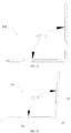
FIG. 3a and FIG. 3b are side views of a partial structure of the data transmission cable shown in FIG. 1, and showing a comparison of the data transmission cable bending at a predetermined angle with bending at a practical angle;
FIG. 4 is a front view of the data transmission cable shown in FIG. 3 b;
FIG. 5 is an enlarged schematic view of a front end surface of the data transmission cable shown in FIG. 4, for showing the configuration of the data transmission cable distinctly;
FIG. 6a is an impedance change diagram of a traditional data transmission cable after bending;
FIG. 6b is an impedance change diagram of the data transmission cable shown in FIG. 3 b;
FIG. 7 is an insertion loss diagram of the data transmission cable shown in FIG. 3b as bending and revoking bending;
FIG. 8 is a front view of a data transmission cable in accordance with a second embodiment of the present disclosure; and
FIG. 9 is a perspective view of a data transmission cable before bending in accordance with a third embodiment of the present disclosure, showing a state of a metallic layer and a mylar layer spiral winding thereon.
DETAILED DESCRIPTION OF THE ILLUSTRATED EMBODIMENT
Reference will now be made to the drawing figures to describe the embodiments of the present disclosure in detail. In the following description, the same drawing reference numerals are used for the same elements in different drawings.
The present disclosure relates to a flat data transmission cable, and the data transmission cable comprises at least a plurality of juxtaposed wires and a plastic layer enclosing on the wires integrally, a detailed illustration of several preferred embodiments is as follow.
Referring to FIGS. 1 to 7, a first embodiment of the present disclosure discloses a data transmission cable 100, a state diagram of the data transmission cable 100 before bending is shown in FIGS. 1 to 2, and an actual state diagram of the data transmission cable 100 after bending is shown in FIGS. 4 to 5.
Conjunction with FIGS. 1 to 7, the data transmission cable 100 comprises a plurality of juxtaposed wires 1, a plastic layer 2 enclosing on the wires 1 integrally and a metallic layer 3 formed by a metal material belt arranged on an outer side of the plastic layer 2 in a spiral winding way.
Conjunction with FIGS. 1 to 5, in the present embodiment, each wire 1 has a conductor 11 and an insulative cladding layer 12 enclosing on the conductor 11. Central axes of the conductors 11 are located on a same plane, the plastic layer 2 is enclosing on the cladding layers 12 to form a common single insulation layer. The plastic layer 2 defines a top surface and a bottom surface parallel to the plane in which the central axes of the conductors 11 located. As the top surface of the plastic layer 2 parallel to the bottom surface, the arrangement of the conductors 11 can be effectively maintained for preventing distortion or folding. Furthermore, the winding arrangement of the metallic layer 3 can be further facilitated for avoiding air interlayer between the plastic layer 2 and the metallic layer 3.
The conductors 11 can be well protected by the cladding layer 12, thereby preventing short circuit caused by two adjacent conductors 11 contacting during the forming process of the plastic layer 2. Moreover, the thickness of the plastic layer 2 can also be set as light as possible when the wire 1 having the cladding layer 12, just making sure that the relative position of all wires 1, and then the thickness of the whole data transmission cable 100 can be reduced, thus the whole of data transmission cable 100 can be made much thinner and much softer.
The cladding layer 12 is made of same or similar material as the plastic layer 2, and preferably made of same kind material, thus when the data transmission cable 100 in the present invention is molded, the combination of the plastic layer 2 and the cladding layer 12 is better, and a good fusion can be achieved with minimizing the stratification problem or air entry, thus the forming effect is better.
Further, the same kind material is a polyhydrocarbon compound, and further, the polyhydrocarbon compound is preferably a high density polyethylene.
In addition, the plastic layer 2 and the cladding layer 12 can be preferably made of plastic material with a dielectric coefficient close to air, therefore the impedance of the cladding layer 12 and the plastic layer 2 can be reduced, and a better signal transmission environment can be provided for the conductors 11, the propagation delay of signals and crosstalk between signals can be reduced to ensure high-speed and effective transmission of signals and reduce signal attenuation.
When the wire 1 having the cladding layer 12, in the thickness direction of the data transmission cable 100, the distance between the outer edge of the conductor 11 and the outer edge of the plastic layer 2 is in the range of 0.1 mm to 0.45 mm, and preferably in the range of 0.15 mm to 0.25 mm. The above distance is also the distance between the conductor 11 and metallic layer 3, and one of the factors affecting the stable signal transmission of the wire 1, especially the high frequency data transmission. As the distance is smaller, the impedance is smaller and the high frequency performance is better. At the same time, the thickness of the whole data transmission cable 100 is smaller, and the data transmission cable 100 can be softer and thinner. However, if the thickness of the whole data transmission cable 100 is too small, the metallic layer 3 will affect signal transmission of the conductors 11, and the above-mentioned interval of the invention can better meet various requirements.
A second embodiment of the present disclosure is disclosed in FIG. 8, each wire 1 also can have only the conductor 11 without the cladding layer 12, that is, the plastic layer 2 is directly enclosing on the wires 1, and the same effect can be achieved. By adopting the setting, the thickness of the plastic layer 2 can be further reduced, and the overall thickness of the data transmission cable 100 can be further reduced.
In further, the wires 1 are disposed in an equally spaced arrangement in present embodiment, and in the arrangement direction of the wires 1, the number of the wires 1 is in the range of 3 to 50. The wires 1 define at least two grounding wires and at least a signal wire between the two grounding wires. Therefore, the interference around the signal wire can be eliminated by grounding wire, and the signal transmission environment of the signal wire can be guaranteed, thereby improving the efficiency and stability of signal transmission.
As a preferred embodiment of the present invention, in order to meet the development needs of high-speed signal transmission, the number of the signal wires between two adjacent ground wires is preferably two. And the two signal wires constitute a signal wire group for transmitting differential signals, that is to say, the grounding wire is used for protecting the signal wire group to ensure the high frequency transmission performance.
Additionally, referring to FIG. 5, the wires 1 only comprise a plurality of grounding wires g and several signal wire groups s, and the number of grounding wires g is one more than that of the signal wire groups s. Preferably, in the arrangement direction of the wires 1, the two wires 1 on both sides are grounding wires g, and one signal wire group s is arranged between every two neighboring grounding wires g. Thus, each signal wire group can be protected by two neighboring grounding wires on both sides thereof, and the high frequency transmission characteristics of the whole data transmission cable 100 can be further improved.
In other embodiment of the present invention, in order to correspond with other single-ended signal transmission, the signal wires also define at least one single-ended signal wire. Such as the number of the signal wires is twice as that of the grounding wires, to accommodate Mini SAS (Mini Serial Attached Small Computer System Interface) standard, and in the arrangement direction of the wires 1, two single-ended signal wires are defined on outer sides of the grounding pads, that is to say, two single-ended signal wires are located on both sides of the entire data transmission cable 100, the grounding wires and the signal wire groups are arranged between the two single-ended signal wires in proper sequence.
Furthermore, in another embodiment of present invention, the data transmission cable 100 also can be provided with a plurality of grounding wires and a plurality of single-ended signal wires. Such as the number of the grounding wires is one more than that of the single-ended signal wires, to accommodate narrow version of Mini SAS standard. The specific arrangement is as follows: the two wires 1 on both sides are grounding wires to shield the whole data transmission cable 100 from both sides thereof, and in the arrangement direction of the wires 1, the grounding wires and the signal wires are arranged alternately.
In the present invention, all the conductors 11 of the wires 1 have a same outer diameter, and the ratio of the center distance between every two neighboring wires 1 to the outer diameter of the conductor 11 is preferably in the range of 1.4 to 2.8. By this setting, when the wires 1 are provided with differential signal wire groups, the differential impedance of each differential signal wire group can be effectively reduced and controlled in the range of 75 to 110 Ohm, to enhance coupling effect and ensure long-distance transmission of high frequency signals.
In an optimized embodiment of present invention, the wires 1 define a plurality of differential signal wire groups, according to the setting of the plastic layer 2 and the metallic layer 3, when the ratio of the center distance between two adjacent wires 1 in each differential signal wire group to the outer diameter of the conductor 11 is in the range of 1.4 to 2.8, the differential impedance of the differential signal wire group is in the range of 79 to 106 Ohm.
Specifically, while the ratio of the center distance between two adjacent wires 1 in a same signal wire group to the outer diameter of the conductor 11 is in the range of 1.55 to 2.31, the differential impedance of the wires 1 in each signal wire group can be controlled in the range of 79 to 91 Ohm.
As a preferable embodiment of the present invention, in order to further ensure the softness and lightness of the data transmission cable 100, the conductor 11 has an outer diameter (traditionally expressed in AWG size) in the range of 31 to 33 American Wire Gauge (AWG), at this time, the center distance between two neighboring wires 1 in each signal wire group is defined in the range of 0.28 mm to 0.52 mm, to ensure the differential impedance of the wires 1 in each signal wire group in the range of 79 to 91 Ohm.
Among them, while the outer diameter of the conductor 11 is 31 AWG, the center distance between two neighboring wires 1 in each signal wire group is defined in the range of 0.44 mm to 0.52 mm, to guarantee the differential impedance of the wires 1 in each signal wire group in the range of 79 to 91 Ohm. Specifically, while the center distance between two neighboring wires 1 is 0.48 mm, the differential impedance of the wires 1 in each signal wire group can be controlled with 85 Ohm.
While the outer diameter of the conductor 11 is 32 AWG, the center distance between two neighboring wires 1 in each signal wire group is defined in the range of 0.36 mm to 0.44 mm, to guarantee the differential impedance of the wires 1 in each signal wire group in the range of 79 to 91 Ohm. Specifically, while the center distance between two neighboring wires 1 is 0.40 mm, the differential impedance of the wires 1 in each signal wire group can be controlled with 85 Ohm.
While the outer diameter of the conductor 11 is 33 AWG, the center distance between two neighboring wires 1 in each signal wire group is defined in the range of 0.28 mm to 0.36 mm, to guarantee the differential impedance of the wires 1 in each signal wire group in the range of 79 to 91 Ohm. Specifically, while the center distance between two neighboring wires 1 is 0.32 mm, the differential impedance of the wires 1 in each signal wire group can be controlled with 85 Ohm.
In addition, while the ratio of the center distance between two adjacent wires 1 in a same signal wire group to the outer diameter of the conductor 11 is in the range of 2.18 to 2.84, the differential impedance of the wires 1 in each signal wire group can be controlled in the range of 94 to 106 Ohm.
In an optimized embodiment of present invention, to ensure the softness and lightness of the data transmission cable 100, the conductor 11, the outer diameter of the conductor 11 is 33 AWG or 34 AWG, the center distance between two neighboring wires 1 in each signal wire group is defined in the range of 0.35 mm to 0.51 mm, to guarantee the differential impedance of the wires 1 in each signal wire group in the range of 94 to 106 Ohm.
Among them, in present invention, while the outer diameter of the conductor 11 is 33 AWG, the center distance between two neighboring wires 1 in each signal wire group is defined in the range of 0.43 mm to 0.51 mm, to guarantee the differential impedance of the wires 1 in each signal wire group in the range of 94 to 106 Ohm. Specifically, while the center distance between two neighboring wires 1 is 0.48 mm, the differential impedance of the wires 1 in each signal wire group can be controlled with 100 Ohm.
While the outer diameter of the conductor 11 is 34 AWG, the center distance between two neighboring wires 1 in each signal wire group is defined in the range of 0.35 mm to 0.43 mm, to guarantee the differential impedance of the wires 1 in each signal wire group in the range of 94 to 106 Ohm. Specifically, while the center distance between two neighboring wires 1 is 0.40 mm, the differential impedance of the wires 1 in each signal wire group can be controlled with 100 Ohm.
Preferably, each wire 1 has the conductor 11 and the insulative cladding layer 12, and center distance between every two neighboring wires 1 is equal to the outer diameter of the wire 1, that is to say every two neighboring wires 1 are abutting each other, thus it's convenient for forming the data transmission cable 100.
As mentioned, the plastic layer 2 is enclosing on the wires 1 integrally, the metallic layer 3 is formed by a metal belt arranged on an outer side of the plastic layer 2 in a spiral winding way, therefore compact winding and bonding between the metallic layer 3 and the plastic layer 2 can be realized, and an intimate enclosing is formed by the metallic layer 3, on the premise of the data transmission cable 100 having the metallic layer 3 shielding interference, the data transmission cable 100 can be made more thinner and softer, and the overall thickness of the data transmission cable 100 can be controlled in the range of 0.3 mm to 1 mm.
Among them, conjunction with the aforementioned two embodiments, each wire 1 can or cannot have the cladding layer 12. After the wire 1 integrally covered by the plastic layer 2, the overall thickness d2 of the wire 1 and the plastic layer 2 can be controlled in the range of 0.25 mm to 0.8 mm Combining with the conductor 11 has an outer diameter in the range of 31 to 34 AWG, the overall thickness d2 of the wire 1 and the plastic layer 2 can be controlled in the range of 0.3 mm to 0.6 mm. Furthermore, for example, while the outer diameter of the conductor 11 is 32 AWG, the wire 1 defines the cladding layer 12 with a thickness of 0.1 mm, and the thickness of the plastic layer 2 is 0.07 mm, thus the overall thickness d2 of the wire 1 and the plastic layer 2 can be controlled with 0.54 mm Certainly, the thickness of the cladding layer 12 and the plastic layer 2 can be adjusted according to actual needs and technical capabilities, and specific settings is not restricted to the conductor 11 with 32 AWG.
In further, conjunction with FIGS. 1 to 5 in present embodiment, the metallic layer 3 has at least an aluminum foil layer 31 and a bonding layer 32 arranged on the side of the aluminum foil layer 31 facing to the plastic layer 2, thus the metallic layer 3 is bonded to the outer side of the plastic layer 2 by the bonding layer 32. By the setting of the aluminum foil layer 31, the external electromagnetic interference can be effectively shielded, the conductors 11 of the signal wire group are effectively isolated from the outside world to ensure the transmission of high frequency or ultra-high frequency signal. In addition, the metallic layer 3 also has fire protection function, which can make the data transmission cable 100 reach horizontal flame retardant grade of FT-2 rating and vertical flame retardant grade of VW-1 rating.
Furthermore, on the one hand, the metallic layer 3 is arranged on an outer side of the plastic layer 2 in a spiral winding way, thus tight winding and bonding between the metallic layer 3 and the plastic layer 2 can be realized. On the premise of guaranteeing shielding and fire protection, the overall volume of the data transmission cable 100 is reduced as much as possible. On the other hand, the bonding layer 32 is arranged on the side of the metallic layer 3 facing to the plastic layer 2, the metallic layer 3 can not only be fixed on the outer side of the plastic layer 2 directly by bonding without a mylar layer, thus the whole of data transmission cable 100 can be made much thinner and much softer. But also air can be discharged when bonding, and as bonding, the discharged air cannot enter again, so as to achieve a dense effect and an intimate enclosing, therefore the data transmission cable 100 can be made more softer and more lightweight with a high frequency transmission performance.
Furthermore, the bonding layer 32 is connecting the plastic layer 2 and the aluminum foil layer 31 by hot melting, to facilitate the setting of the bonding layer 32 and the winding of the metallic layer 3, at the same time, the bonding strength and closeness of the metallic layer 3 and the plastic layer 2 can be increased. The metallic layer 3 further has an insulating layer 36 arranged on the side of the aluminum foil layer 31 deviating from the plastic layer 2, the insulating layer 36 can replace the mylar layer in the prior art, insulate the outside and protect the aluminum foil layer 31 at the same time.
Furthermore, combining with the aforementioned two embodiments, the metallic layer 3 can or cannot have the insulating layer, the whole thickness d1 of the metallic layer 3 is defined in the range of 0.010 mm to 0.055 mm, to minimize the thickness of the data transmission cable 100 on the basis of realizing external shielding. Preferably, the whole thickness d1 of the metallic layer 3 is defined in the range of 0.015 mm to 0.025 mm.
Combining with the setting of the conductor 11, the cladding layer 12, the plastic layer 2 and the thickness of the metallic layer 3, the thickness of the data transmission cable 100 can be controlled in the range of 0.35 mm to 0.65 mm. For example, while the outer diameter of the conductor 11 is 32 AWG, the overall thickness d2 of the wire 1 and the plastic layer 2 is about 0.54 mm, and the thickness of the metallic layer 3 is 0.045 mm, thus the thickness of the data transmission cable 100 can be of 0.63 mm Certainly, the thickness of the cladding layer 12, the plastic layer 2 and the metallic layer 3 can be adjusted according to actual needs and technical capabilities, and specific settings is not restricted to above embodiments.
Additionally, the metal belt in a spiral winding way of present invention can be designed as: The width of the metal belt is set as W, in a length direction of the data transmission cable 100, the metal belt is wound with N rings, the data transmission cable 100 has a length L, and the requirement of L<N*W should be satisfied. By winding setting, besides the data transmission cable 100 can be guaranteed with a compact structure and for minimizing the size thereof as much as possible, and have a fire-proof property. And the impedance discontinuity caused by bending can be effectively reduced, thereby ensuring the stability of signal transmission, especially high frequency signal transmission.
Preferably, an overlapping coating area 35 is formed between every two adjacent rings of the metal belt, and the overlapping coating area 35 has a width w along the width direction of the metal belt, the proportion of the width w of the overlapping coating area 35 occupying the width W of the metal belt is 5% to 50%. The width w of the overlapping coating area 35 is at least 0.5 mm, preferably not less than 0.8 mm and optimally 1 mm, thus, the winding continuity of the metallic layer 3 can be effectively guaranteed. When the data transmission cable 100 is bent, cracking phenomenon of the metallic layer 3 can be effectively avoided, thereby effectively avoiding the phenomenon of discontinuous impedance and ensuring the stability of signal transmission, especially high frequency signal transmission.
Further, the winding angle of the metal belt relative to the width direction of the data transmission cable 100 is in the range of 40° to 55°, and preferably 45° to 53°. With the above setting, the flexibility of the data transmission cable 100 in the length direction thereof is more uniform, and it is not easy to cause cracks when bending.
Furthermore, the width W of the metal belt is defined not less than half of the whole width of the data transmission cable 100, preferably not less than 0.75 times of the whole width of the data transmission cable 100, optimally not less than one times of the whole width of the data transmission cable 100. With the above setting of the width W, the winding of the metal belt is more convenient and the compactness of the winding can be controlled conveniently, and at the same time, the softness of the entire data transmission cable 100 after winding can be guaranteed. Additionally, the overlapping area of the entire data transmission cable 100 at per unit length can be less, thereby further reducing the possibility of the metal belt spreading when bending.
Further, it is assumed that there is a center distance d0 between two adjacent wires 1 in the present invention, the number of the wires 1 is n, the whole width of the data transmission cable 100 is defined in the range of d0*n to d0*(n+2). The ratio of the whole width of the data transmission cable 100 to n is 1 to 1.25 times of the width, thus it ensures that the plastic layer 2 with a certain width still can be defined on both outer sides of wires 1 in the width direction of the data transmission cable 100, but the plastic layer 2 on both sides of the data transmission cable 100 in the width direction will not be too large to increase the whole width of the data transmission cable 100, thus an effective protection for the wires 1 can be realized as the plastic layer 2 having a minimal size.
With the above configuration, the weight of per centimeter as a unit length of the data transmission cable 100 is in the range of 0.015 g to 0.30 g. Moreover, in the case of per centimeter as a unit length, the ratio of the weight of the data transmission cable 100 to the number of wires 1 is in the range of 0.0080 to 0.0020. Therefore, the data transmission cable 100 is not only flexible with higher frequency stability, but also more portable.
FIG. 9 illustrates a data transmission cable 100′ according to a third embodiment of the present invention before bending, the status of the data transmission cable 100′ after bending is shown in FIG. 3a to FIG. 5, compared with the first embodiment described above, the data transmission cable 100′ further includes a mylar layer 4 coated on the outside of the metallic layer 3′.
With the above configuration, the metallic layer 3′ can only have the aluminum foil layer, also can have the aluminum foil layer and the bonding layer same as the first embodiment, and further can have the insulating layer, thus, an encapsulation compaction effect of the metallic layer 3′ can be guaranteed further by the mylar layer 4.
Additionally, in the present embodiment, the mylar layer 4 is also defined in a spiral winding way, and adhesive glue is arranged on the side of the mylar layer 4 facing the metallic layer 3′. The mylar layer 4 is fixed to the outer side of the metallic layer 3′ by the adhesive glue after hot melting, thereby ensuring the coating effect of the mylar layer 4 as compact as that of the metallic layer 3′. Preferably, the mylar layer 4 and the metallic layer 3′ are defined in a cross-winding way, to guarantee the winding of the metallic layer 3′, and further reduce or avoid the phenomenon of impedance discontinuity, for guaranteeing the stability of signal transmission.
Additionally, in another embodiment shown in FIG. 8, the data transmission cable 100 can be defined without the cladding layer 12′ on the basis of the embodiment shown in FIG. 9, that is to say, the plastic layer 2′ is directly enclosing on the conductors 11 of the wires, which also can achieve the purpose of the present invention.
Additionally, combining with FIGS. 3a, 3b and 4, in the length direction of the data transmission cable 100, the data transmission cable 100 has at least one bending portion 101, thus the data transmission cable 100 is formed with a first section 102 and a second section 103 on both sides of the bending portion 101, and a stable bending angle is formed between the first section 102 and the second section 103.
As aforementioned, on the one hand, by the wires 1 of the data transmission cable 100 being arranged abreast with the plastic layer 2 enclosing on the outer side of the wires 1 integrally, thus the thickness of the whole data transmission cable 100 can be thinner. On the other hand, the metal belt is spirally wound on the outer side of the plastic layer 2 to realize the close winding and bonding between the metallic layer 3 and the plastic layer 2, and the coating of the metallic layer 3 is more compact, the data transmission cable 100 can be made thinner and softer under the premise of the metallic layer 3 shielding interference. Combining with the above two points, the data transmission cable 100 can be bent with a stable bending angle without an auxiliary tool, it is convenient for installation and connection in subsequent equipment.
The data transmission cable 100 is bending at a predetermined bending angle to form the bending portion, by above setting of the plastic layer 2 and the metallic layer 3, the difference between the stable bending angle after bending and the predetermined bending angle can be less than 10 degrees. Comparison between FIG. 3a and FIG. 3b , when the predetermined bending angle is 90 degrees, the practical bending angle shown in FIG. 3b is 5 degrees larger than the predetermined bending angle in FIG. 3a . In the figures, only one bending portion with bending at 90 degrees is shown simply by illustration, in practical use, various angles and/or multiple bending portions can be carried out according to requirements.
Additionally, an impedance change diagram of a traditional data transmission cable after bending is shown in FIG. 6a , we can see the impedance change at the bending portion is about 13 Ohm; FIG. 6b is a testing schematic diagram of the data transmission cable 100 in a better embodiment of the present disclosure, the data transmission cable 100 has multiple bending portions, be seen From FIG. 6b , a small fluctuation is found at some locations during the test, which are the bending positions of the data transmission cable 100. However, it can be seen that the average impedance change of the data transmission cable 100 of the present invention at least once mentioned above is not greater than 2 Ohm, in other words, the difference between the average impedance of the data transmission cable 100 with at least one bending portion and the predetermined impedance of the data transmission cable is not greater than 2 Ohm. Specially, the impedance change of the data transmission cable 100 at each bending portion is not greater than 2 Ohm, that is to say, the difference between the impedance of the data transmission cable 100 at each bending portion and the predetermined impedance is not greater than 2 Ohm.
Additionally, after testing, signal delay of the data transmission cable 100 with the bending portions is not greater than 5 picoseconds per unit length.
Referring to FIG. 7, insertion loss of the data transmission cable 100 after bending in signal transmission is shown, curve a shows the signal transmission loss of the data transmission cable 100 as revoking bending, curve b shows the signal transmission loss of the data transmission cable 100 as bending. From the comparison of the curves, at the same frequency, the insertion loss of the data transmission cable 100 after bending compared with revoking bending, the difference therebetween is less than 10%. Moreover, the difference between the reflection loss of the data transmission cable 100 after bending and that of revoking bending is less than 10%.
It is to be understood, however, that even though numerous characteristics and advantages of preferred and exemplary embodiments have been set out in the foregoing description, together with details of the structures and functions of the embodiments, the disclosure is illustrative only; and that changes may be made in detail within the principles of present disclosure to the full extent indicated by the broadest general meaning of the terms in which the appended claims are expressed.

Claims (19)

What is claimed is:
1. A flat data transmission cable, comprising:
a plurality of juxtaposed wires;
a plastic layer enclosing on the wires integrally;
a metallic layer formed by a metal material belt arranged on an outer side of the plastic layer in a spiral winding way;
wherein in the length direction of the data transmission cable, the data transmission cable has at least one bending portion, the data transmission cable is formed with a first section and a second section on both sides of the bending portion, and a stable bending angle is formed between the first section and the second section, the wires comprise a plurality of grounding wires and a plurality of signal wires, two signal wires neighboring to each other constitute a signal wire group, the wires are disposed in an equally spaced arrangement, and conductors of the wires have a same outer diameter, and the ratio of the center distance between every two neighboring wires to the outer diameter of the conductor is in the range of 1.4 to 2.8.
2. A flat data transmission cable, comprising:
a plurality of juxtaposed wires;
a plastic layer enclosing on the wires integrally;
a metallic layer formed by a metal material belt arranged on an outer side of the plastic layer in a spiral winding way;
wherein in the length direction of the data transmission cable, the data transmission cable has at least one bending portion, the data transmission cable is formed with a first section and a second section on both sides of the bending portion, and a stable bending angle is formed between the first section and the second section, the metal belt has a width W, in a length direction of the data transmission cable, the metal belt is wound with N rings, the data transmission cable has a length L, and the requirement of L<N*W is satisfied.
3. The flat data transmission cable as claimed in claim 1, wherein the data transmission cable is bent at a predetermined bending angle to form the bending portion, and the difference between the stable bending angle after bending and the predetermined bending angle is less than 10 degrees.
4. The flat data transmission cable as claimed in claim 1, wherein the difference between the average impedance of the data transmission cable with at the least one bending portion and the predetermined impedance of the data transmission cable is not greater than 2 Ohm.
5. The flat data transmission cable as claimed in claim 4, wherein the difference between the impedance of the data transmission cable at said at least one bending portion and the predetermined impedance of the data transmission cable is not greater than 2 Ohm.
6. The flat data transmission cable as claimed in claim 1, wherein signal delay of the data transmission cable is not greater than 5 picoseconds per unit length.
7. The flat data transmission cable as claimed in claim 1, wherein the difference between the insertion loss of the data transmission cable after bending and that of revoking bending is less than 10%, and the plastic layer is made from polyhydrocarbon compound.
8. The flat data transmission cable as claimed in claim 7, wherein the difference between the reflection loss of the data transmission cable after bending and that of revoking bending is less than 10%.
9. The flat data transmission cable as claimed in claim 1, wherein the metal belt has a width W, in a length direction of the data transmission cable, the metal belt is wound with N rings, the data transmission cable has a length L, and the requirement of L<N*W is satisfied.
10. The flat data transmission cable as claimed in claim 9, wherein an overlapping coating area is formed between every two adjacent rings of the metal belt, and the overlapping coating area has a width w along the width direction of the metal belt, the proportion of the width w of the overlapping coating area occupying the width W of the metal belt is 5% to 50%.
11. The flat data transmission cable as claimed in claim 10, wherein the width w of the overlapping coating area is at least 0.5 mm.
12. The flat data transmission cable as claimed in claim 10, wherein the winding angle of the metal belt relative to the width direction of the data transmission cable is in the range of 40° to 55°.
13. The flat data transmission cable as claimed in claim 9, wherein the width of the metal belt is defined not less than half of the whole width of the data transmission cable.
14. The flat data transmission cable as claimed in claim 1, wherein the metallic layer has at least an aluminum foil layer and a bonding layer arranged on the side of the aluminum foil layer facing to the plastic layer, the metallic layer is bonded to the outer side of the plastic layer by the bonding layer after hot melting.
15. The flat data transmission cable as claimed in claim 14, wherein the metallic layer further has an insulating layer arranged on the side of the aluminum foil layer deviating from the plastic layer, the whole thickness of the metallic layer is defined in the range of 0.010 mm to 0.055 mm.
16. The flat data transmission cable as claimed in claim 1, further comprising a mylar layer coated on the outside of the metallic layer, wherein the mylar layer is also defined on the metallic layer in a spiral winding way, the mylar layer and the metallic layer are further defined in a cross-winding way.
17. The flat data transmission cable as claimed in claim 1, wherein the data transmission cable has a horizontal flame retardant grade of FT-2 rating.
18. The flat data transmission cable as claimed in claim 1, wherein each wire has a conductor and an insulative cladding layer enclosing on the conductor, the cladding layer is made from polyhydrocarbon compound.
19. The flat data transmission cable as claimed in claim 18, wherein the cladding layer is made of same material as the plastic layer.
US16/408,354 2018-06-01 2019-05-09 Flat data transmission cable Active US10772202B2 (en)

Applications Claiming Priority (9)

Application Number Priority Date Filing Date Title
CN201810556982 2018-06-01
CN201810556982.0 2018-06-01
CN201810556982 2018-06-01
CN201821732499 2018-10-24
CN201821732499U 2018-10-24
CN201821730509.1 2018-10-24
CN201821732499.5 2018-10-24
CN201821730509 2018-10-24
CN201821730509U 2018-10-24

Publications (2)

Publication Number Publication Date
US20190371493A1 US20190371493A1 (en) 2019-12-05
US10772202B2 true US10772202B2 (en) 2020-09-08

Family

ID=68692782

Family Applications (4)

Application Number Title Priority Date Filing Date
US16/408,316 Active US10772201B2 (en) 2018-06-01 2019-05-09 Flat data transmission cable
US16/408,454 Active US10827612B2 (en) 2018-06-01 2019-05-09 Printed circuit board and electrical connector assembly using the same
US16/408,387 Active US10772203B2 (en) 2018-06-01 2019-05-09 Flat data transmission cable
US16/408,354 Active US10772202B2 (en) 2018-06-01 2019-05-09 Flat data transmission cable

Family Applications Before (3)

Application Number Title Priority Date Filing Date
US16/408,316 Active US10772201B2 (en) 2018-06-01 2019-05-09 Flat data transmission cable
US16/408,454 Active US10827612B2 (en) 2018-06-01 2019-05-09 Printed circuit board and electrical connector assembly using the same
US16/408,387 Active US10772203B2 (en) 2018-06-01 2019-05-09 Flat data transmission cable

Country Status (3)

Country Link
US (4) US10772201B2 (en)
CN (9) CN209980819U (en)
WO (4) WO2019228277A1 (en)

Families Citing this family (6)

* Cited by examiner, † Cited by third party
Publication number Priority date Publication date Assignee Title
CN209729555U (en) * 2018-06-01 2019-12-03 凡甲电子(苏州)有限公司 Flat data transmission cable
CN209980819U (en) * 2018-06-01 2020-01-21 凡甲电子(苏州)有限公司 Flat data transmission cable
CN111029790A (en) * 2019-12-30 2020-04-17 京信通信技术(广州)有限公司 Antenna, auxiliary device and wire clamp assembly
TWM611875U (en) * 2021-01-18 2021-05-11 品威電子國際股份有限公司 Luminescent flat cable
CN115458215A (en) * 2021-05-21 2022-12-09 泰科电子(上海)有限公司 Ribbon cable
CN219761418U (en) 2023-03-13 2023-09-26 深圳市和鑫晟智连科技有限公司 FPC winding displacement and data line

Citations (6)

* Cited by examiner, † Cited by third party
Publication number Priority date Publication date Assignee Title
US3735022A (en) * 1971-09-22 1973-05-22 A Estep Interference controlled communications cable
US5180890A (en) * 1991-03-03 1993-01-19 Independent Cable, Inc. Communications transmission cable
US20030102148A1 (en) * 2001-12-03 2003-06-05 The Furukawa Electric Co., Ltd. Flat cable and laminated cable harness
US20110232938A1 (en) * 2010-03-26 2011-09-29 Hitachi Cable Fine-Tech, Ltd. Flexible flat cable
US8975521B2 (en) * 2011-09-09 2015-03-10 Hitachi Metals, Ltd. Shielded flat cable and cable harness using the same
US20160300642A1 (en) * 2015-04-10 2016-10-13 Hitachi Metals, Ltd. Differential signal transmission cable and multi-core differential signal transmission cable

Family Cites Families (30)

* Cited by examiner, † Cited by third party
Publication number Priority date Publication date Assignee Title
US4308421A (en) * 1978-01-18 1981-12-29 Virginia Plastics Company EMF Controlled multi-conductor cable
US4220807A (en) * 1978-06-12 1980-09-02 Akzona Incorporated Transmission cable
US4475006A (en) * 1981-03-16 1984-10-02 Minnesota Mining And Manufacturing Company Shielded ribbon cable
US5360944A (en) * 1992-12-08 1994-11-01 Minnesota Mining And Manufacturing Company High impedance, strippable electrical cable
US6630624B2 (en) * 2001-11-08 2003-10-07 Hon Hai Precision Ind. Co., Ltd. Electrical cable with grounding means
US6765150B2 (en) * 2002-08-06 2004-07-20 Angus Hsieh Signal transmission cable structure
JP5309766B2 (en) * 2008-03-03 2013-10-09 住友電気工業株式会社 Shielded flat cable
JP2010102975A (en) * 2008-10-24 2010-05-06 Sumitomo Electric Ind Ltd Shielded flat cable
US7956290B2 (en) * 2009-03-20 2011-06-07 Sure-Fire Electrical Corporation High-frequency digital A/V cable
CN201465619U (en) * 2009-08-05 2010-05-12 佛山市顺德区莱尔电子材料有限公司 Insulating hot melt adhesive polyimide Nylar structure of FFC wire
TW201129263A (en) * 2010-02-12 2011-08-16 Sunplus Technology Co Ltd Circuit substrate
JP5468944B2 (en) * 2010-03-12 2014-04-09 矢崎総業株式会社 Extruded flexible flat cable
JP5816055B2 (en) * 2011-11-02 2015-11-17 矢崎総業株式会社 Shielded wire
CN103198888B (en) * 2012-01-05 2016-04-20 日立金属株式会社 Differential signal transmission cable
CN104898901B (en) * 2014-03-05 2017-10-13 纬创资通股份有限公司 Bonding pad structure and contact panel
CN104347164A (en) * 2014-10-17 2015-02-11 东莞市奕联实业有限公司 High-speed and high-bandwidth flat cable
CN204257244U (en) * 2014-12-29 2015-04-08 安徽蒙特尔电缆集团有限公司 A kind of bent digital signal flat cable
CN106847390B (en) * 2016-08-31 2018-05-15 凡甲电子(苏州)有限公司 Data transmission cable
CN204926884U (en) * 2015-09-18 2015-12-30 安徽华润仪表线缆有限公司 Crosslinked polyethylene shielding frequency conversion cable
CN106997795A (en) * 2016-01-22 2017-08-01 3M创新有限公司 Electrical cable
CN205408281U (en) * 2016-02-02 2016-07-27 嘉基电子科技(苏州)有限公司 Circuit board
CN205508453U (en) * 2016-04-25 2016-08-24 安费诺电子装配(厦门)有限公司 A flat data transmission line for video audio transmission
US10195878B2 (en) * 2016-10-27 2019-02-05 Hewlett-Packard Development Company, L.P. Apparatus for flexible flat cable
CN206441946U (en) * 2016-12-28 2017-08-25 品威电子国际股份有限公司 Flexible flat cable structure and flexible flat cable fixing structure for electrical connector
CN206584738U (en) * 2017-02-21 2017-10-24 凡甲电子(苏州)有限公司 Flat cable
CN107195397B (en) * 2017-05-12 2019-04-30 番禺得意精密电子工业有限公司 The manufacturing method and cable of cable
CN106998091A (en) * 2017-06-05 2017-08-01 尚育生 A kind of novel mobile phone supports charger
CN207319718U (en) * 2017-08-25 2018-05-04 富士康(昆山)电脑接插件有限公司 Flat cable
CN207266368U (en) * 2017-08-30 2018-04-20 东莞铭基电子科技集团有限公司 Cable-assembly and its connector and pcb board
CN209980819U (en) * 2018-06-01 2020-01-21 凡甲电子(苏州)有限公司 Flat data transmission cable

Patent Citations (6)

* Cited by examiner, † Cited by third party
Publication number Priority date Publication date Assignee Title
US3735022A (en) * 1971-09-22 1973-05-22 A Estep Interference controlled communications cable
US5180890A (en) * 1991-03-03 1993-01-19 Independent Cable, Inc. Communications transmission cable
US20030102148A1 (en) * 2001-12-03 2003-06-05 The Furukawa Electric Co., Ltd. Flat cable and laminated cable harness
US20110232938A1 (en) * 2010-03-26 2011-09-29 Hitachi Cable Fine-Tech, Ltd. Flexible flat cable
US8975521B2 (en) * 2011-09-09 2015-03-10 Hitachi Metals, Ltd. Shielded flat cable and cable harness using the same
US20160300642A1 (en) * 2015-04-10 2016-10-13 Hitachi Metals, Ltd. Differential signal transmission cable and multi-core differential signal transmission cable

Also Published As

Publication number Publication date
CN210110378U (en) 2020-02-21
US20190373726A1 (en) 2019-12-05
WO2019228276A1 (en) 2019-12-05
CN210110379U (en) 2020-02-21
WO2019228277A1 (en) 2019-12-05
CN110556200A (en) 2019-12-10
CN209980819U (en) 2020-01-21
US20190371493A1 (en) 2019-12-05
CN209980818U (en) 2020-01-21
US10772201B2 (en) 2020-09-08
US10827612B2 (en) 2020-11-03
CN209980821U (en) 2020-01-21
US20190371492A1 (en) 2019-12-05
CN210112383U (en) 2020-02-21
US10772203B2 (en) 2020-09-08
WO2019228274A1 (en) 2019-12-05
WO2019228275A1 (en) 2019-12-05
CN110556199A (en) 2019-12-10
US20190371491A1 (en) 2019-12-05
CN209980820U (en) 2020-01-21

Similar Documents

Publication Publication Date Title
US10772202B2 (en) Flat data transmission cable
US11289241B2 (en) Shielded flat cable
US10395795B2 (en) Data transmission cable
CN209747165U (en) Flat data transmission cable
US10079082B2 (en) Data transmission cable
TWI778246B (en) Flat data transmission cable
KR20150021181A (en) Communication cable comprising discontinuous shield tape and discontinuous shield tape
US11551831B2 (en) Data transmission cable
US20140060913A1 (en) S-shield twisted pair cable design for multi-ghz performance
US11756704B2 (en) Data transmission cable
CN212647947U (en) Data transmission cable
US20170372818A1 (en) Differential signal transmission cable and multi-core differential signal transmission cable
TWM601889U (en) Data transmission cable
TWM609698U (en) Data transmission cable
KR20230068501A (en) Ethernet cable
TW201907613A (en) Flat data transmission cable

Legal Events

Date Code Title Description
AS Assignment

Owner name: ALLTOP ELECTRONICS (SUZHOU) LTD., CHINA

Free format text: ASSIGNMENT OF ASSIGNORS INTEREST;ASSIGNORS:NI, MINDI;CHEN, YICHANG;REEL/FRAME:049134/0204

Effective date: 20190506

FEPP Fee payment procedure

Free format text: ENTITY STATUS SET TO UNDISCOUNTED (ORIGINAL EVENT CODE: BIG.); ENTITY STATUS OF PATENT OWNER: LARGE ENTITY

STPP Information on status: patent application and granting procedure in general

Free format text: NON FINAL ACTION MAILED

STPP Information on status: patent application and granting procedure in general

Free format text: RESPONSE TO NON-FINAL OFFICE ACTION ENTERED AND FORWARDED TO EXAMINER

STPP Information on status: patent application and granting procedure in general

Free format text: FINAL REJECTION MAILED

STPP Information on status: patent application and granting procedure in general

Free format text: RESPONSE AFTER FINAL ACTION FORWARDED TO EXAMINER

STPP Information on status: patent application and granting procedure in general

Free format text: NOTICE OF ALLOWANCE MAILED -- APPLICATION RECEIVED IN OFFICE OF PUBLICATIONS

STCF Information on status: patent grant

Free format text: PATENTED CASE

FEPP Fee payment procedure

Free format text: MAINTENANCE FEE REMINDER MAILED (ORIGINAL EVENT CODE: REM.); ENTITY STATUS OF PATENT OWNER: LARGE ENTITY