US10748359B2 - Method and system for data reporting using customized triggers - Google Patents

Method and system for data reporting using customized triggers Download PDF

Info

Publication number
US10748359B2
US10748359B2 US15/878,676 US201815878676A US10748359B2 US 10748359 B2 US10748359 B2 US 10748359B2 US 201815878676 A US201815878676 A US 201815878676A US 10748359 B2 US10748359 B2 US 10748359B2
Authority
US
United States
Prior art keywords
trigger
module
data
platform
cdr
Prior art date
Legal status (The legal status is an assumption and is not a legal conclusion. Google has not performed a legal analysis and makes no representation as to the accuracy of the status listed.)
Active, expires
Application number
US15/878,676
Other versions
US20190228599A1 (en
Inventor
Dalibor Hrib
Ondrej Kutal
Jakub Kadlas
Current Assignee (The listed assignees may be inaccurate. Google has not performed a legal analysis and makes no representation or warranty as to the accuracy of the list.)
Honeywell International Inc
Original Assignee
Honeywell International Inc
Priority date (The priority date is an assumption and is not a legal conclusion. Google has not performed a legal analysis and makes no representation as to the accuracy of the date listed.)
Filing date
Publication date
Application filed by Honeywell International Inc filed Critical Honeywell International Inc
Priority to US15/878,676 priority Critical patent/US10748359B2/en
Assigned to HONEYWELL INTERNATIONAL INC. reassignment HONEYWELL INTERNATIONAL INC. ASSIGNMENT OF ASSIGNORS INTEREST (SEE DOCUMENT FOR DETAILS). Assignors: HRIB, DALIBOR, KADLAS, JAKUB, KUTAL, ONDREJ
Priority to EP19152418.0A priority patent/EP3518185A1/en
Publication of US20190228599A1 publication Critical patent/US20190228599A1/en
Application granted granted Critical
Publication of US10748359B2 publication Critical patent/US10748359B2/en
Active legal-status Critical Current
Adjusted expiration legal-status Critical

Links

Images

Classifications

    • GPHYSICS
    • G07CHECKING-DEVICES
    • G07CTIME OR ATTENDANCE REGISTERS; REGISTERING OR INDICATING THE WORKING OF MACHINES; GENERATING RANDOM NUMBERS; VOTING OR LOTTERY APPARATUS; ARRANGEMENTS, SYSTEMS OR APPARATUS FOR CHECKING NOT PROVIDED FOR ELSEWHERE
    • G07C5/00Registering or indicating the working of vehicles
    • G07C5/08Registering or indicating performance data other than driving, working, idle, or waiting time, with or without registering driving, working, idle or waiting time
    • G07C5/0841Registering performance data
    • G07C5/085Registering performance data using electronic data carriers
    • GPHYSICS
    • G07CHECKING-DEVICES
    • G07CTIME OR ATTENDANCE REGISTERS; REGISTERING OR INDICATING THE WORKING OF MACHINES; GENERATING RANDOM NUMBERS; VOTING OR LOTTERY APPARATUS; ARRANGEMENTS, SYSTEMS OR APPARATUS FOR CHECKING NOT PROVIDED FOR ELSEWHERE
    • G07C5/00Registering or indicating the working of vehicles
    • G07C5/008Registering or indicating the working of vehicles communicating information to a remotely located station
    • BPERFORMING OPERATIONS; TRANSPORTING
    • B64AIRCRAFT; AVIATION; COSMONAUTICS
    • B64DEQUIPMENT FOR FITTING IN OR TO AIRCRAFT; FLIGHT SUITS; PARACHUTES; ARRANGEMENT OR MOUNTING OF POWER PLANTS OR PROPULSION TRANSMISSIONS IN AIRCRAFT
    • B64D45/00Aircraft indicators or protectors not otherwise provided for
    • GPHYSICS
    • G06COMPUTING; CALCULATING OR COUNTING
    • G06FELECTRIC DIGITAL DATA PROCESSING
    • G06F16/00Information retrieval; Database structures therefor; File system structures therefor
    • G06F16/20Information retrieval; Database structures therefor; File system structures therefor of structured data, e.g. relational data
    • G06F16/24Querying
    • G06F16/245Query processing
    • G06F16/2455Query execution
    • G06F16/24564Applying rules; Deductive queries
    • G06F16/24565Triggers; Constraints
    • GPHYSICS
    • G07CHECKING-DEVICES
    • G07CTIME OR ATTENDANCE REGISTERS; REGISTERING OR INDICATING THE WORKING OF MACHINES; GENERATING RANDOM NUMBERS; VOTING OR LOTTERY APPARATUS; ARRANGEMENTS, SYSTEMS OR APPARATUS FOR CHECKING NOT PROVIDED FOR ELSEWHERE
    • G07C5/00Registering or indicating the working of vehicles
    • G07C5/08Registering or indicating performance data other than driving, working, idle, or waiting time, with or without registering driving, working, idle or waiting time
    • HELECTRICITY
    • H04ELECTRIC COMMUNICATION TECHNIQUE
    • H04LTRANSMISSION OF DIGITAL INFORMATION, e.g. TELEGRAPHIC COMMUNICATION
    • H04L12/00Data switching networks
    • H04L12/28Data switching networks characterised by path configuration, e.g. LAN [Local Area Networks] or WAN [Wide Area Networks]
    • H04L12/40Bus networks
    • H04L12/40006Architecture of a communication node
    • H04L12/40032Details regarding a bus interface enhancer
    • HELECTRICITY
    • H04ELECTRIC COMMUNICATION TECHNIQUE
    • H04LTRANSMISSION OF DIGITAL INFORMATION, e.g. TELEGRAPHIC COMMUNICATION
    • H04L43/00Arrangements for monitoring or testing data switching networks
    • H04L43/06Generation of reports
    • H04L43/067Generation of reports using time frame reporting
    • BPERFORMING OPERATIONS; TRANSPORTING
    • B64AIRCRAFT; AVIATION; COSMONAUTICS
    • B64DEQUIPMENT FOR FITTING IN OR TO AIRCRAFT; FLIGHT SUITS; PARACHUTES; ARRANGEMENT OR MOUNTING OF POWER PLANTS OR PROPULSION TRANSMISSIONS IN AIRCRAFT
    • B64D45/00Aircraft indicators or protectors not otherwise provided for
    • B64D2045/0085Devices for aircraft health monitoring, e.g. monitoring flutter or vibration
    • HELECTRICITY
    • H04ELECTRIC COMMUNICATION TECHNIQUE
    • H04LTRANSMISSION OF DIGITAL INFORMATION, e.g. TELEGRAPHIC COMMUNICATION
    • H04L12/00Data switching networks
    • H04L12/28Data switching networks characterised by path configuration, e.g. LAN [Local Area Networks] or WAN [Wide Area Networks]
    • H04L12/40Bus networks
    • H04L2012/40267Bus for use in transportation systems
    • H04L2012/4028Bus for use in transportation systems the transportation system being an aircraft
    • HELECTRICITY
    • H04ELECTRIC COMMUNICATION TECHNIQUE
    • H04LTRANSMISSION OF DIGITAL INFORMATION, e.g. TELEGRAPHIC COMMUNICATION
    • H04L67/00Network arrangements or protocols for supporting network services or applications
    • H04L67/01Protocols
    • H04L67/12Protocols specially adapted for proprietary or special-purpose networking environments, e.g. medical networks, sensor networks, networks in vehicles or remote metering networks

Definitions

  • the present invention generally relates to mobile platform data reporting systems, and more particularly relates to methods and systems for data reporting using customized triggers.
  • Mobile platforms such as aircraft, comprise multiple subsystems, each generating a tremendous amount of data.
  • the data is then communicated via one or more data busses, such as, an aircraft Avionics Standard Communication Bus (ASCB), during operation.
  • ASCB aircraft Avionics Standard Communication Bus
  • ASCB aircraft Avionics Standard Communication Bus
  • on-board storage space is limited, therefore determining what data is recorded, and when, is necessary.
  • Determining a set of triggers (to record data) in advance of operation and recording only a preselected set of parameters may help, but since it is difficult to determine in advance what data may be needed to study an issue, it may still be desirable to record all of the data made available on all of the busses. Therefore, solutions tend to result in unwieldy database size, or inadequate stored data.
  • a data reporting system for a platform comprising: a navigation system providing navigation data; an avionics system providing avionics data; a trigger module operatively coupled to the navigation system and the avionics system, and configured to process a platform-specific configuration file (CF) during platform operation and generate therefrom a customized data report (CDR); and a ground station (GS) module external to the platform, the GS module configured to generate the platform-specific configuration file (CF); and wherein the trigger module is configured to: process the avionics data and the navigation data with the CF to: determine (a) that a trigger occurred, and (b) a trigger identity; responsive to determining that a trigger occurred, record data bus activity for a duration of time associated with the trigger identity in the CF; generate the CDR including the record of data bus activity; and transmit the CDR to the GS module via a wireless communication link; and the GS module is configured to: reference trigger logic in a trigger logic library and aircraft (A/C) specific parameters based on a first
  • a method for data reporting for a platform comprising: at a trigger module, receiving navigation data; receiving avionics data; processing the avionics data and the navigation data with a platform-specific configuration file (CF) during platform operation to determine (a) whether a trigger occurred, and (b) a trigger identity; responsive to determining that a trigger occurred, (i) recording data bus activity for a duration of time associated with the trigger identity, (ii) generating a customized data report (CDR) including the record of data bus activity; and (iii) transmitting the CDR to a ground station (GS) module external to the platform, via a wireless communication link; and at the ground station (GS) module, referencing trigger logic in a trigger logic library and aircraft (A/C) specific parameters based on a first user input to generate therefrom the platform-specific CF, wherein the first user input represents a first user-specific selection of trigger logic modules in the trigger logic library; transmitting the CF to the trigger module via the wireless communication link; and responsive to receiving the
  • a method for data reporting for an aircraft comprising: at a ground station (GS) module external to the aircraft, creating a trigger library comprising multiple trigger logic modules based on a first user input and aircraft specific parameters, the trigger logic modules each being platform-specific and directed to one or more categories from the set including: safety, engine status, fault detection, and avionic system status; generating an aircraft-specific configuration file (CF) based on a second user input and the trigger logic library; and transmitting the CF to a trigger module in the aircraft via a wireless communication link; and at the trigger module, receiving the platform-specific configuration file (CF); receiving navigation data, avionics data, and sensor system data; processing the avionics data, the navigation data, and the sensor system data with the (CF) during aircraft operation to monitor for triggers; determining (a) that a trigger occurred, and (b) a trigger identity; and responsive to determining that the trigger occurred, (i) recording data bus activity for a duration of time associated with the trigger identity, (ii) generating
  • GS ground
  • FIG. 1 is a block diagram of a data recording system, in accordance with an exemplary embodiment.
  • FIG. 2 and FIG. 3 are flow charts for a method for data recording for a platform, in accordance with an exemplary embodiment.
  • Exemplary embodiments of the novel disclosed data reporting system provide a technologically improved method and system to generate data reports by allowing customers to select from multiple predefined trigger logic modules that each have respective data recording times.
  • the disclosed data reporting system 100 enables reuse of the multiple predefined trigger logic modules by multiple customers.
  • the disclosed data reporting system 100 further partitions hardware and software functionality between a platform ( FIG. 1, 102 ) and a ground station ( FIG. 1, 104 ).
  • a streamlined executable file (program) is loaded onto the platform 102 , and the more frequently changed software, such as the multiple trigger logic modules, are stored and revised off of the platform 102 .
  • the novel data reporting system 100 minimizes certification efforts of on-platform software via the partitioning of the files. Operation of the data reporting system 100 includes communications between the platform 102 and the ground station 104 , via a communications link ( FIG. 1, 105 ).
  • the data reporting system 100 comprises a trigger system 106 and a ground station (GS) system 108 operatively coupled via the communications link 105 .
  • the trigger system 106 is generally located in a mobile platform 102 , whereas the GS system 108 is external to the platform 102 , and envisioned to be at a ground station 104 .
  • the platform 102 is an aircraft, and is referred to as aircraft 102 .
  • the aircraft 102 may be a first aircraft of a plurality of aircraft, each having therein a respective trigger system 106 configured to communicate with the GS system 108 .
  • the GS system 108 is configured to individually and concurrently communicate with a plurality of aircraft 102 .
  • module refers to any hardware, software, firmware, electronic control component, processing logic, and/or processor device, individually or in any combination, configured to facilitate communications and/or interaction between the elements of the data reporting system 100 and perform additional processes, tasks and/or functions to support operation of the data reporting system 100 , as described herein.
  • the modules may be implemented or realized with a general purpose processor (shared, dedicated, or group) controller, microprocessor, or microcontroller, and memory that executes one or more software or firmware programs; a content addressable memory; a digital signal processor; an application specific integrated circuit (ASIC), a field programmable gate array (FPGA); any suitable programmable logic device; combinational logic circuit including discrete gates or transistor logic; discrete hardware components and memory devices; and/or any combination thereof, designed to perform the functions described herein.
  • a general purpose processor shared, dedicated, or group
  • microprocessor, or microcontroller and memory that executes one or more software or firmware programs
  • a content addressable memory a digital signal processor
  • ASIC application specific integrated circuit
  • FPGA field programmable gate array
  • any suitable programmable logic device combinational logic circuit including discrete gates or transistor logic; discrete hardware components and memory devices; and/or any combination thereof, designed to perform the functions described herein.
  • the trigger system 106 embodies a trigger module 50 .
  • the trigger module 50 may be separate from, or integrated within, a preexisting mobile platform management system, avionics system, flight controls system (FCS), or aircraft flight management system (FMS).
  • the GS system 108 embodies a ground station (GS) module 60 .
  • the trigger module 50 comprises a processor 20 , memory comprising a novel program 22 , and I/O interface 24
  • the GS module 60 comprises a processor 30 , memory comprising a novel program 32 , and I/O interface 34 .
  • the novel program 22 and novel program 32 are each embodied in a memory (e.g., RAM memory, ROM memory, flash memory, registers, a hard disk, or the like) or another suitable non-transitory short or long term storage media capable of storing computer-executable programming instructions or other data for execution.
  • program 22 and program 32 each include rules and instructions which, when executed, cause the data reporting system 100 to perform the functions, techniques, and processing tasks associated with the operation of the data reporting system 100 described in greater detail below.
  • the trigger module 50 communicates with multiple aircraft systems via an avionics standard communication bus (ACSB), data bus 51 .
  • the trigger module 50 may be operatively coupled to any combination of the following aircraft systems: a navigation system 110 , one or more avionics systems 112 , one or more on-board sensor systems 114 , a user interface 116 , a display system 118 , a communications system 120 , and one or more data storage elements (DB 1 ) 122 .
  • the functions of these aircraft systems, and their interaction, is described in more detail below.
  • the data and information provided by the multiple aircraft systems is collectively described as data bus activity (in other words, data bus activity comprises, without limitation, changes in navigation data, avionics data, onboard sensor system data, and communication system data, over time).
  • the trigger module 50 is configured to process a platform-specific configuration file (CF), to monitor and record data bus activity pursuant thereto, and to generate therefrom a customized data report (CDR), described in more detail below.
  • CF platform
  • the trigger module 50 is coupled to the navigation system 110 , which, as used herein, comprises a flight management system FMS, and is configured to provide real-time navigational data and/or information regarding operation of the aircraft 102 , including real-time flight guidance for aircraft 102 .
  • the navigation system 110 may be realized as a global positioning system (GPS), inertial reference system (IRS), or a radio-based navigation system (e.g., VHF omni-directional radio range (VOR) or long range aid to navigation (LORAN)), and may include one or more navigational radios or other sensors suitably configured to support operation of the navigation system 110 , as will be appreciated in the art.
  • GPS global positioning system
  • IRS inertial reference system
  • LORAN long range aid to navigation
  • the navigation system 110 is capable of obtaining and/or determining the instantaneous position of the aircraft 102 , that is, the current (or instantaneous) location of the aircraft 102 (e.g., the current latitude and longitude) and the current (or instantaneous) altitude (or above ground level) for the aircraft 102 .
  • the navigation system 110 is also capable of obtaining or otherwise determining the heading of the aircraft 102 (i.e., the direction the aircraft is traveling in relative to some reference), and to compare the instantaneous position of the aircraft 102 with an intended flight plan for the aircraft 102 .
  • the various data, information, and guidance, determined by the navigation system 110 are referred to herein as navigation data.
  • Navigation data is made available to the data bus 51 such that one or more of the other onboard systems 112 , 114 , 116 , 118 , 120 , and the trigger module 50 , may further process and/or handle the navigation data.
  • the avionics system(s) 112 include numerous systems for obtaining and/or providing real-time flight-related data and information.
  • avionics systems 112 may include any combination of: a weather system, an air traffic management system, a radar system, a traffic avoidance system, an autopilot system, an auto thrust system, a flight control system, hydraulics systems, pneumatics systems, environmental systems, electrical systems, engine systems, trim systems, lighting systems, crew alerting systems, electronic checklist systems, an electronic flight bag and/or another suitable avionics system.
  • Each of these avionics systems 112 generates respective data; the entirety of data from the avionics system(s) 112 is referred to herein as avionics data.
  • Avionics data is made available to the data bus 51 such that one or more of the other onboard systems 110 , 114 , 116 , 118 , 120 , and the trigger module 50 , may further process and/or handle the avionics data.
  • the onboard sensor system(s) 114 generally represent the component(s) of the aircraft 102 that sense, detect, or otherwise identify a respective status of various aircraft systems and subsystems.
  • the onboard sensor system(s) 114 may sense status of a specific avionics system 112 , subsystem, surface, component, line replacement unit (LRU), or the like.
  • the sensor system(s) 114 provides sensor data including real-time system status data to the data bus 51 .
  • the sensor system(s) 114 also provide a respective status of objects or regions of interest in the vicinity of the aircraft 102 .
  • an onboard sensor system 114 may be realized as a weather radar system or other weather sensing system that measures, senses, or otherwise detects meteorological conditions in the vicinity of the aircraft 102 .
  • the sensor data therefore, comprises real-time system status data and weather data.
  • the sensor system(s) 114 provides sensor data to the data bus 51 such that one or more of the other onboard systems 110 , 112 , 116 , 118 , 120 , and trigger module 50 may further process and/or handle the sensor data.
  • the user interface may include, without limitation, an input device 130 and an audio system 132 .
  • the user input device 130 is coupled to the trigger module 50 , and the user input device 130 and the trigger module 50 are cooperatively configured to allow a user (e.g., a pilot, co-pilot, or crew member) to interact with the display device 40 and/or other elements of the data reporting system 100 , as described in greater detail below.
  • the user input device 130 may be realized as a keypad, touchpad, keyboard, mouse, touch panel (or touchscreen), joystick, knob, line select key or another suitable device adapted to receive input from a user.
  • the audio system 132 may include an audio input device, such as a microphone, audio transducer, audio sensor, or the like, that is adapted to receive voice input, thus allowing a user to provide audio input triggers to the data reporting system 100 in a “hands free” manner without requiring the user to move his or her hands, eyes and/or head to interact with the data reporting system 100 .
  • the audio system 132 may also include any suitable audio input device to detect/monitor cabin noise. Audio output data from the audio system 132 is made available on the data bus 51 for further use and processing.
  • the trigger module 50 comprises rules and instructions to processes audio output data to identify (i) words or phrases that indicate distress (such as “fire”) and (ii) unusual noises (such as rattling or knocking sounds).
  • the trigger module 50 is also coupled to the communications system 120 , which is configured to support communications to and/or from the aircraft 102 via the communications link 105 .
  • the communications link 105 may comprise one or more wireless communication networks, such as a datalink, a communication management function (CMF) uplink, and a terminal wireless local area network (LAN) unit (TWLU).
  • the communications system 120 may include a data link system, automatic dependent surveillance broadcast system (ADS-B), or any other suitable radio communication system that supports communications between the aircraft 102 and one or more external monitoring systems, air traffic control, and/or another command center or ground station 104 .
  • ADS-B automatic dependent surveillance broadcast system
  • the communications system 120 may allow the aircraft 102 to receive information that would otherwise be unavailable to the pilot and/or co-pilot using the onboard systems 110 , 112 , 114 , 116 .
  • the navigation system 110 , avionics system(s) 112 , onboard sensor system(s) 114 , and communications system 120 are coupled to the display system 118 such that the display system 118 may generate or render, on a display device 40 , real-time information associated with the respective components.
  • the navigation system 110 , avionics system(s) 112 , onboard sensor system(s) 114 , and communications system 120 are configured to support navigation, flight planning, and other aircraft control functions in a conventional manner, as well as to provide real-time data and/or information regarding the operational status of the aircraft 102 to the trigger module 50 .
  • the display device 40 is realized as one or more electronic displays capable of graphically rendering flight information or other data associated with operation of the aircraft 102 .
  • the display device 40 is configured to be responsive to display commands from the display system 118 and/or trigger module 50 .
  • the trigger module 50 and the display system 118 are cooperatively configured to generate the display commands for the display device 40 to display, render, or otherwise convey thereon one or more graphical representations or images associated with operation of the aircraft 102 , and the various menu selections on the display device 40 .
  • the display device 40 may render a lateral, navigational map (navigation display, ND) that includes a graphical representation of the aircraft 102 and one or more of the terrain, meteorological conditions, airspace, air traffic, navigational reference points, and a route associated with a lateral flight plan of the aircraft 102 .
  • the display device 40 may also render a vertical map, or vertical situation display (VSD), that includes a graphical representation of the aircraft 102 and one or more of the airspace, air traffic, navigational reference points, and a vertical flight plan associated with a flight plan of the aircraft 102 .
  • VSD vertical situation display
  • the data storage element or database DB 1 122 may maintain information regarding airports and/or other potential landing locations (or destinations) for the aircraft 102 .
  • the DB 1 122 maintains an association between a respective airport, its geographic location, runways (and their respective orientations and/or directions), instrument procedures (e.g., approaches, arrival routes, and the like), airspace restrictions, and/or other information or attributes associated with the respective airport (e.g., widths and/or weight limits of taxi paths, the type of surface of the runways or taxi path, and the like).
  • the DB 1 122 also maintains airport status information for the runways and/or taxi paths at the airport indicating whether or not a particular runway and/or taxi path is currently operational along with directional information for the taxi paths (or portions thereof).
  • the DB 1 122 may also be utilized to store or maintain other information pertaining to the airline or aircraft operator (e.g., contractual agreements or other contractual availability information for particular airports, maintenance capabilities or service availability information for particular airports, and the like) along with information pertaining to the pilot and/or co-pilot of the aircraft (e.g., experience level, licensure or other qualifications, work schedule or other workload metrics, such as stress or fatigue estimates, and the like).
  • the GS system 108 is external to the platform 102 , such as at a ground station 104 .
  • the GS module 60 is configured to generate the platform-specific configuration file (CF).
  • the GS module 60 may be operatively coupled to a GS communications system 150 , a GS user interface 152 , a trigger logic library 154 , and an aircraft (A/C) specific parameters database 156 .
  • the GS communications system 150 and the GS user interface 152 may be functionally equivalent to the user interface 116 and communication system(s) 120 described above.
  • the provided trigger logic library 154 includes a first plurality of predefined trigger logic modules, each being platform-specific and directed to one or more categories from the set including: safety, engine status, fault detection, and avionic system status. Each trigger logic module may comprise a trigger identity and a default time for recording data bus 51 activity.
  • the trigger logic library 154 is organized to be reused by multiple users, and the trigger logic modules may be determined well in advance of configuration file generation.
  • the A/C specific parameters database 156 stores component information associated with various aircraft models.
  • the data reporting system 100 may be used to implement a method 200 , as shown in the flow charts of FIG. 2 and FIG. 3 .
  • method 200 may refer to elements mentioned above in connection with FIG. 1 .
  • portions of method 200 may be performed by different components of the described system.
  • method 200 may include any number of additional or alternative tasks, the tasks shown in FIG. 2 and FIG. 3 need not be performed in the illustrated order, and method 200 may be incorporated into a more comprehensive procedure or method having additional functionality not described in detail herein.
  • one or more of the tasks shown in FIG. 2 and FIG. 3 could be omitted from an embodiment of the method 200 as long as the intended overall functionality remains intact.
  • Initialization generally comprises uploading or updating instructions and applications as required for operation of the trigger system 106 and as required for operation of the GS system 108 . This may include: authentication protocols used in connection with the communications link 105 ; the executable programs 22 and 32 ; the DB 1 122 ; the A/C specific parameters database 156 ; and, any associated stored variables.
  • initialization comprises uploading an initial trigger logic library 154 and an initial configuration file CF. The initial configuration file is created from the trigger logic library.
  • executable program 22 is loaded into memory in the trigger module 50 .
  • the trigger module 50 receives an aircraft-specific configuration file. Receiving the aircraft (A/C) specific configuration file may be responsive to first having requested it.
  • the executable program 22 is initialized with the received A/C specific configuration file (CF).
  • the A/C is in operation.
  • the trigger module 50 is in operation.
  • the trigger module 50 is receiving and processing data and information from one or more of the navigation system 110 , one or more avionics systems 112 , one or more on-board sensor systems 114 , the user interface 116 , the communications system 120 , and one or more data storage elements (DB 1 ) 122 . While the trigger module 50 is in operation at 210 , it is monitoring the received data and information for triggers, i.e., it is processing any combination of: the avionics data, the navigation data, the sensor data, and the communications data, with the CF to: determine (a) that a trigger occurred, and (b) a corresponding trigger identity.
  • DB 1 data storage elements
  • the trigger identity is used to employ the associated predetermined default time to record data bus activity.
  • Data bus activity is then recorded for the associated default time, creating, in conjunction with the trigger identity, a first block of data.
  • the customized data report (CDR) is generated from the first block of recorded data bus activity.
  • the CDR and/or the first block of data bus activity may also be stored.
  • the CDR is transmitted to the GS system 108 .
  • transmission of information between the GS system 108 and the aircraft 102 may comprise first establishing an authenticated connection.
  • the transmission at 216 occurs after the aircraft 102 has completed its flight. In other embodiments, the transmission at 216 may occur during flight.
  • the method may return to 210 and continue monitoring received data and information for triggers.
  • a subsequent trigger may result in a subsequent block of recorded data.
  • the subsequent block of recorded data may be appended to the first block of recorded data, and the generated CDR may include the first block of recorded data and the second block of recorded data. This process may continue until the aircraft 102 lands.
  • trigger logic is generated.
  • the trigger logic comprises multiple trigger logic modules that are generated using A/C specific parameters and user input.
  • the trigger logic is stored in the trigger logic library 154 . If there has not been a receipt of a CDR at 254 , and a configuration file (CF) request arrives at 256 , then a CF is generated using the files in the trigger logic library 154 .
  • the CF is transmitted.
  • the CDR may be processed with A/C specific parameters and user input at 262 to identify updates to trigger logic modules at 264 .
  • the user input may be responsive to a technical review of the CDR and A/C specific parameters.
  • the technical review of the CDR and A/C specific parameters may include the GS module 60 further being configured to: identify the trigger; and prompt a technical review of the trigger and associated record of data bus activity. Users, such as engineers and technicians, may perform the technical reviews, identify updates ( 264 ), and revise individual trigger logic modules ( 266 ).
  • the trigger logic library 154 is continually updated ( 268 ) with revised trigger logic modules. Accordingly, the trigger logic library 154 is current, and a request for a configuration file at 256 initiates the generation of a configuration file ( 258 ) and transmission of a configuration file ( 260 ) that reflects the most recent trigger logic modules.
  • the referenced users may be platform customers, original equipment manufacturers (OEMs), manufacturers of individual aircraft systems and components, engineers, technicians, and the like.
  • the user input associated with a request for a configuration file at 256 may represent a first user-specific selection of trigger logic modules in the trigger logic library.
  • the user input at 262 (associated with a technical review of the CDR) may or may not be from the same user as the user that provided the user input at 256 .
  • a user requesting a first CF may be one of a plurality of users.
  • the method 200 and system 100 are further configured to: receive, from each of the plurality of users, a respective user-specific selection of the trigger logic modules; generate a respective plurality of CF, each CF of the plurality of CF being responsive to a respective one of the user-specific selections of trigger logic modules; and transmit each CF of the plurality of CFs to its respective user.
  • the system and method may further store the plurality of user-specific CF for future analysis.
  • the method 200 may revise each CF of the plurality of stored CFs responsive to the revised trigger logic. As mentioned, these updates to the trigger logic library and to the CFs are performed off-platform.
  • the trigger system 106 may employ an audio system 132 , configured to continuously detect audible emissions and ambient noise in the platform and generate audio data based thereon.
  • program 22 enables the trigger module 50 to receive and process the audio data to distinguish between spoken commands and ambient cabin noises; and identify the trigger from among either the spoken commands or the ambient cabin noises.
  • the trigger module 50 may monitor the audio data to determine (a) that the trigger occurred, and (b) the trigger identity based on processing the audio data with the CF.
  • the trigger logic library 154 may comprise audio trigger logic modules. Audio trigger logic modules comprise trigger identifications associated with various words, phrases, types of sounds, and loudness (decibel) thresholds, and provide associated default record times as described herein.
  • the trigger module 50 may process received user input data to determine that a user has manipulated a user input device 130 to force a trigger.
  • the identified trigger is a user initiated trigger, and again, a predetermined default record time may be employed.
  • the user may force the trigger, and also force the amount of record time. Responsive thereto, the trigger module 50 records all data bus activity for the required amount of time, and the CDR is generated as before.
  • the exemplary embodiments discussed above provide a technologically improved method and system to record data during operation of an aircraft 102 .
  • a technological benefit of the provided data recording systems and methods is the leaning-out of the onboard software (program 22 ) by moving bulky and frequently changing software (program 32 ) to a ground system (GS) 108 .
  • having the frequently changing software (program 32 ) reside external to the aircraft 102 means that (i) the trigger logic library 154 may be frequently revised without necessitating recertification of the onboard software (program 22 ), and (ii) trigger logic modules may be selected and reused on an as-needed basis.

Landscapes

  • Engineering & Computer Science (AREA)
  • Physics & Mathematics (AREA)
  • General Physics & Mathematics (AREA)
  • Computer Networks & Wireless Communication (AREA)
  • Signal Processing (AREA)
  • Theoretical Computer Science (AREA)
  • Aviation & Aerospace Engineering (AREA)
  • Computational Linguistics (AREA)
  • Data Mining & Analysis (AREA)
  • Databases & Information Systems (AREA)
  • General Engineering & Computer Science (AREA)
  • Traffic Control Systems (AREA)

Abstract

Methods and systems for data recording for an aircraft are provided. The method includes a ground station (GS) module external to the aircraft, and a trigger module onboard the aircraft. The GS module performs: creating a trigger library comprising multiple trigger logic modules based on a first user input and aircraft specific parameters; generating an aircraft-specific configuration file (CF) based on a second user input and the trigger logic library; and transmitting the CF to the trigger module. The trigger module performs: receiving the CF; receiving and processing the CF with various aircraft signals during aircraft operation to monitor for triggers; and, responsive to determining that the trigger occurred, (i) recording data bus activity for a duration of time associated with the trigger identity, (ii) generating a customized data report (CDR) including the record of data bus activity, and (iii) transmitting the CDR to the GS module.

Description

TECHNICAL FIELD
The present invention generally relates to mobile platform data reporting systems, and more particularly relates to methods and systems for data reporting using customized triggers.
BACKGROUND
Mobile platforms, such as aircraft, comprise multiple subsystems, each generating a tremendous amount of data. The data is then communicated via one or more data busses, such as, an aircraft Avionics Standard Communication Bus (ASCB), during operation. In order to study aircraft operation and increase design and operational efficiency, it is desirable to record this data, and have it readily available for review as necessary. However, on-board storage space is limited, therefore determining what data is recorded, and when, is necessary.
Determining a set of triggers (to record data) in advance of operation and recording only a preselected set of parameters may help, but since it is difficult to determine in advance what data may be needed to study an issue, it may still be desirable to record all of the data made available on all of the busses. Therefore, solutions tend to result in unwieldy database size, or inadequate stored data.
Accordingly, improved methods and systems for data reporting directed to controlling time frames for data recording, enabling modular construction, and enabling reuse of triggers by multiple stakeholders are desired. Desirable systems and methods also minimize certification requirements of on-board software. Furthermore, other desirable features and characteristics of the present disclosure will become apparent from the subsequent Detailed Description and the appended claims, taken in conjunction with the accompanying drawings and this Background.
BRIEF SUMMARY
This summary is provided to describe select concepts in a simplified form that are further described in the Detailed Description. This summary is not intended to identify key or essential features of the claimed subject matter, nor is it intended to be used as an aid in determining the scope of the claimed subject matter.
A data reporting system for a platform is provided, the system comprising: a navigation system providing navigation data; an avionics system providing avionics data; a trigger module operatively coupled to the navigation system and the avionics system, and configured to process a platform-specific configuration file (CF) during platform operation and generate therefrom a customized data report (CDR); and a ground station (GS) module external to the platform, the GS module configured to generate the platform-specific configuration file (CF); and wherein the trigger module is configured to: process the avionics data and the navigation data with the CF to: determine (a) that a trigger occurred, and (b) a trigger identity; responsive to determining that a trigger occurred, record data bus activity for a duration of time associated with the trigger identity in the CF; generate the CDR including the record of data bus activity; and transmit the CDR to the GS module via a wireless communication link; and the GS module is configured to: reference trigger logic in a trigger logic library and aircraft (A/C) specific parameters based on a first user input to generate therefrom the platform-specific CF, wherein the trigger logic includes a first plurality of predefined trigger logic modules, each being platform-specific and directed to one or more categories from the set including: safety, engine status, fault detection, and avionic system status; and transmit the CF to the trigger module via the wireless communication link; and responsive to receiving the CDR, (a) process the CDR with a second user input to thereby identify a trigger logic update; (b) update a trigger library with a revised trigger logic; and (c) revise the CF responsive to the revised trigger logic.
A method for data reporting for a platform is provided. The method comprising: at a trigger module, receiving navigation data; receiving avionics data; processing the avionics data and the navigation data with a platform-specific configuration file (CF) during platform operation to determine (a) whether a trigger occurred, and (b) a trigger identity; responsive to determining that a trigger occurred, (i) recording data bus activity for a duration of time associated with the trigger identity, (ii) generating a customized data report (CDR) including the record of data bus activity; and (iii) transmitting the CDR to a ground station (GS) module external to the platform, via a wireless communication link; and at the ground station (GS) module, referencing trigger logic in a trigger logic library and aircraft (A/C) specific parameters based on a first user input to generate therefrom the platform-specific CF, wherein the first user input represents a first user-specific selection of trigger logic modules in the trigger logic library; transmitting the CF to the trigger module via the wireless communication link; and responsive to receiving the CDR, (a) processing the CDR with a second user input to thereby identify a trigger logic update; and, (b) updating a trigger library with a revised trigger logic.
Also provided is a method for data reporting for an aircraft. The method comprising: at a ground station (GS) module external to the aircraft, creating a trigger library comprising multiple trigger logic modules based on a first user input and aircraft specific parameters, the trigger logic modules each being platform-specific and directed to one or more categories from the set including: safety, engine status, fault detection, and avionic system status; generating an aircraft-specific configuration file (CF) based on a second user input and the trigger logic library; and transmitting the CF to a trigger module in the aircraft via a wireless communication link; and at the trigger module, receiving the platform-specific configuration file (CF); receiving navigation data, avionics data, and sensor system data; processing the avionics data, the navigation data, and the sensor system data with the (CF) during aircraft operation to monitor for triggers; determining (a) that a trigger occurred, and (b) a trigger identity; and responsive to determining that the trigger occurred, (i) recording data bus activity for a duration of time associated with the trigger identity, (ii) generating a customized data report (CDR) including the record of data bus activity; and (iii) transmitting the CDR to the GS module.
Furthermore, other desirable features and characteristics of the system and method will become apparent from the subsequent detailed description and the appended claims, taken in conjunction with the accompanying drawings and the preceding background.
BRIEF DESCRIPTION OF THE DRAWINGS
The present invention will hereinafter be described in conjunction with the following drawing figures, wherein like numerals denote like elements, and
FIG. 1 is a block diagram of a data recording system, in accordance with an exemplary embodiment; and
FIG. 2 and FIG. 3 are flow charts for a method for data recording for a platform, in accordance with an exemplary embodiment.
DETAILED DESCRIPTION
The following detailed description is merely illustrative in nature and is not intended to limit the embodiments of the subject matter or the application and uses of such embodiments. As used herein, the word “exemplary” means “serving as an example, instance, or illustration.” Thus, any embodiment described herein as “exemplary” is not necessarily to be construed as preferred or advantageous over other embodiments. All of the embodiments described herein are exemplary embodiments provided to enable persons skilled in the art to make or use the invention and not to limit the scope of the invention that is defined by the claims. Furthermore, there is no intention to be bound by any theory presented in the preceding background or the following detailed description.
Exemplary embodiments of the novel disclosed data reporting system (FIG. 1, 100) provide a technologically improved method and system to generate data reports by allowing customers to select from multiple predefined trigger logic modules that each have respective data recording times. The disclosed data reporting system 100 enables reuse of the multiple predefined trigger logic modules by multiple customers. The disclosed data reporting system 100 further partitions hardware and software functionality between a platform (FIG. 1, 102) and a ground station (FIG. 1, 104). A streamlined executable file (program) is loaded onto the platform 102, and the more frequently changed software, such as the multiple trigger logic modules, are stored and revised off of the platform 102. The novel data reporting system 100 minimizes certification efforts of on-platform software via the partitioning of the files. Operation of the data reporting system 100 includes communications between the platform 102 and the ground station 104, via a communications link (FIG. 1, 105).
Turning now to FIG. 1, in an embodiment, the data reporting system 100 comprises a trigger system 106 and a ground station (GS) system 108 operatively coupled via the communications link 105. The trigger system 106 is generally located in a mobile platform 102, whereas the GS system 108 is external to the platform 102, and envisioned to be at a ground station 104. In various embodiments, the platform 102 is an aircraft, and is referred to as aircraft 102. The aircraft 102 may be a first aircraft of a plurality of aircraft, each having therein a respective trigger system 106 configured to communicate with the GS system 108. Accordingly, the GS system 108 is configured to individually and concurrently communicate with a plurality of aircraft 102.
As used herein, the term “module” refers to any hardware, software, firmware, electronic control component, processing logic, and/or processor device, individually or in any combination, configured to facilitate communications and/or interaction between the elements of the data reporting system 100 and perform additional processes, tasks and/or functions to support operation of the data reporting system 100, as described herein. Depending on the embodiment, the modules may be implemented or realized with a general purpose processor (shared, dedicated, or group) controller, microprocessor, or microcontroller, and memory that executes one or more software or firmware programs; a content addressable memory; a digital signal processor; an application specific integrated circuit (ASIC), a field programmable gate array (FPGA); any suitable programmable logic device; combinational logic circuit including discrete gates or transistor logic; discrete hardware components and memory devices; and/or any combination thereof, designed to perform the functions described herein.
The trigger system 106 embodies a trigger module 50. The trigger module 50 may be separate from, or integrated within, a preexisting mobile platform management system, avionics system, flight controls system (FCS), or aircraft flight management system (FMS). The GS system 108 embodies a ground station (GS) module 60. In various embodiments, the trigger module 50 comprises a processor 20, memory comprising a novel program 22, and I/O interface 24, and the GS module 60 comprises a processor 30, memory comprising a novel program 32, and I/O interface 34. In accordance with one or more embodiments, the novel program 22 and novel program 32 are each embodied in a memory (e.g., RAM memory, ROM memory, flash memory, registers, a hard disk, or the like) or another suitable non-transitory short or long term storage media capable of storing computer-executable programming instructions or other data for execution. In practice, program 22 and program 32 each include rules and instructions which, when executed, cause the data reporting system 100 to perform the functions, techniques, and processing tasks associated with the operation of the data reporting system 100 described in greater detail below.
The trigger module 50 communicates with multiple aircraft systems via an avionics standard communication bus (ACSB), data bus 51. The trigger module 50 may be operatively coupled to any combination of the following aircraft systems: a navigation system 110, one or more avionics systems 112, one or more on-board sensor systems 114, a user interface 116, a display system 118, a communications system 120, and one or more data storage elements (DB 1) 122. The functions of these aircraft systems, and their interaction, is described in more detail below. The data and information provided by the multiple aircraft systems is collectively described as data bus activity (in other words, data bus activity comprises, without limitation, changes in navigation data, avionics data, onboard sensor system data, and communication system data, over time). As an overview, the trigger module 50 is configured to process a platform-specific configuration file (CF), to monitor and record data bus activity pursuant thereto, and to generate therefrom a customized data report (CDR), described in more detail below.
Still referring to FIG. 1, in an exemplary embodiment, the trigger module 50 is coupled to the navigation system 110, which, as used herein, comprises a flight management system FMS, and is configured to provide real-time navigational data and/or information regarding operation of the aircraft 102, including real-time flight guidance for aircraft 102. The navigation system 110 may be realized as a global positioning system (GPS), inertial reference system (IRS), or a radio-based navigation system (e.g., VHF omni-directional radio range (VOR) or long range aid to navigation (LORAN)), and may include one or more navigational radios or other sensors suitably configured to support operation of the navigation system 110, as will be appreciated in the art. The navigation system 110 is capable of obtaining and/or determining the instantaneous position of the aircraft 102, that is, the current (or instantaneous) location of the aircraft 102 (e.g., the current latitude and longitude) and the current (or instantaneous) altitude (or above ground level) for the aircraft 102. The navigation system 110 is also capable of obtaining or otherwise determining the heading of the aircraft 102 (i.e., the direction the aircraft is traveling in relative to some reference), and to compare the instantaneous position of the aircraft 102 with an intended flight plan for the aircraft 102. The various data, information, and guidance, determined by the navigation system 110, are referred to herein as navigation data. Navigation data is made available to the data bus 51 such that one or more of the other onboard systems 112, 114, 116, 118, 120, and the trigger module 50, may further process and/or handle the navigation data.
The avionics system(s) 112 include numerous systems for obtaining and/or providing real-time flight-related data and information. For example, avionics systems 112 may include any combination of: a weather system, an air traffic management system, a radar system, a traffic avoidance system, an autopilot system, an auto thrust system, a flight control system, hydraulics systems, pneumatics systems, environmental systems, electrical systems, engine systems, trim systems, lighting systems, crew alerting systems, electronic checklist systems, an electronic flight bag and/or another suitable avionics system. Each of these avionics systems 112 generates respective data; the entirety of data from the avionics system(s) 112 is referred to herein as avionics data. Avionics data is made available to the data bus 51 such that one or more of the other onboard systems 110, 114, 116, 118, 120, and the trigger module 50, may further process and/or handle the avionics data.
In the illustrated embodiment, the onboard sensor system(s) 114 generally represent the component(s) of the aircraft 102 that sense, detect, or otherwise identify a respective status of various aircraft systems and subsystems. For example, the onboard sensor system(s) 114 may sense status of a specific avionics system 112, subsystem, surface, component, line replacement unit (LRU), or the like. The sensor system(s) 114 provides sensor data including real-time system status data to the data bus 51. The sensor system(s) 114 also provide a respective status of objects or regions of interest in the vicinity of the aircraft 102. For example, an onboard sensor system 114 may be realized as a weather radar system or other weather sensing system that measures, senses, or otherwise detects meteorological conditions in the vicinity of the aircraft 102. The sensor data, therefore, comprises real-time system status data and weather data. The sensor system(s) 114 provides sensor data to the data bus 51 such that one or more of the other onboard systems 110, 112, 116, 118, 120, and trigger module 50 may further process and/or handle the sensor data.
The user interface may include, without limitation, an input device 130 and an audio system 132. The user input device 130 is coupled to the trigger module 50, and the user input device 130 and the trigger module 50 are cooperatively configured to allow a user (e.g., a pilot, co-pilot, or crew member) to interact with the display device 40 and/or other elements of the data reporting system 100, as described in greater detail below. Depending on the embodiment, the user input device 130 may be realized as a keypad, touchpad, keyboard, mouse, touch panel (or touchscreen), joystick, knob, line select key or another suitable device adapted to receive input from a user. The audio system 132 may include an audio input device, such as a microphone, audio transducer, audio sensor, or the like, that is adapted to receive voice input, thus allowing a user to provide audio input triggers to the data reporting system 100 in a “hands free” manner without requiring the user to move his or her hands, eyes and/or head to interact with the data reporting system 100. The audio system 132 may also include any suitable audio input device to detect/monitor cabin noise. Audio output data from the audio system 132 is made available on the data bus 51 for further use and processing. In various embodiments, the trigger module 50 comprises rules and instructions to processes audio output data to identify (i) words or phrases that indicate distress (such as “fire”) and (ii) unusual noises (such as rattling or knocking sounds).
In the illustrated embodiment, the trigger module 50 is also coupled to the communications system 120, which is configured to support communications to and/or from the aircraft 102 via the communications link 105. The communications link 105 may comprise one or more wireless communication networks, such as a datalink, a communication management function (CMF) uplink, and a terminal wireless local area network (LAN) unit (TWLU). The communications system 120 may include a data link system, automatic dependent surveillance broadcast system (ADS-B), or any other suitable radio communication system that supports communications between the aircraft 102 and one or more external monitoring systems, air traffic control, and/or another command center or ground station 104. In this regard, the communications system 120 may allow the aircraft 102 to receive information that would otherwise be unavailable to the pilot and/or co-pilot using the onboard systems 110, 112, 114, 116.
In various embodiments, the navigation system 110, avionics system(s) 112, onboard sensor system(s) 114, and communications system 120, are coupled to the display system 118 such that the display system 118 may generate or render, on a display device 40, real-time information associated with the respective components. In this manner, the navigation system 110, avionics system(s) 112, onboard sensor system(s) 114, and communications system 120 are configured to support navigation, flight planning, and other aircraft control functions in a conventional manner, as well as to provide real-time data and/or information regarding the operational status of the aircraft 102 to the trigger module 50.
In exemplary embodiments, the display device 40 is realized as one or more electronic displays capable of graphically rendering flight information or other data associated with operation of the aircraft 102. The display device 40 is configured to be responsive to display commands from the display system 118 and/or trigger module 50. In this regard, the trigger module 50 and the display system 118 are cooperatively configured to generate the display commands for the display device 40 to display, render, or otherwise convey thereon one or more graphical representations or images associated with operation of the aircraft 102, and the various menu selections on the display device 40. For example, the display device 40 may render a lateral, navigational map (navigation display, ND) that includes a graphical representation of the aircraft 102 and one or more of the terrain, meteorological conditions, airspace, air traffic, navigational reference points, and a route associated with a lateral flight plan of the aircraft 102. The display device 40 may also render a vertical map, or vertical situation display (VSD), that includes a graphical representation of the aircraft 102 and one or more of the airspace, air traffic, navigational reference points, and a vertical flight plan associated with a flight plan of the aircraft 102.
The data storage element or database DB1 122 may maintain information regarding airports and/or other potential landing locations (or destinations) for the aircraft 102. In this regard, the DB1 122 maintains an association between a respective airport, its geographic location, runways (and their respective orientations and/or directions), instrument procedures (e.g., approaches, arrival routes, and the like), airspace restrictions, and/or other information or attributes associated with the respective airport (e.g., widths and/or weight limits of taxi paths, the type of surface of the runways or taxi path, and the like). Additionally, in accordance with one or more embodiments, the DB1 122 also maintains airport status information for the runways and/or taxi paths at the airport indicating whether or not a particular runway and/or taxi path is currently operational along with directional information for the taxi paths (or portions thereof). The DB1 122 may also be utilized to store or maintain other information pertaining to the airline or aircraft operator (e.g., contractual agreements or other contractual availability information for particular airports, maintenance capabilities or service availability information for particular airports, and the like) along with information pertaining to the pilot and/or co-pilot of the aircraft (e.g., experience level, licensure or other qualifications, work schedule or other workload metrics, such as stress or fatigue estimates, and the like).
With continued reference to FIG. 1, the GS system 108 is external to the platform 102, such as at a ground station 104. The GS module 60 is configured to generate the platform-specific configuration file (CF). The GS module 60 may be operatively coupled to a GS communications system 150, a GS user interface 152, a trigger logic library 154, and an aircraft (A/C) specific parameters database 156. The GS communications system 150 and the GS user interface 152 may be functionally equivalent to the user interface 116 and communication system(s) 120 described above.
The provided trigger logic library 154 includes a first plurality of predefined trigger logic modules, each being platform-specific and directed to one or more categories from the set including: safety, engine status, fault detection, and avionic system status. Each trigger logic module may comprise a trigger identity and a default time for recording data bus 51 activity. The trigger logic library 154 is organized to be reused by multiple users, and the trigger logic modules may be determined well in advance of configuration file generation. The A/C specific parameters database 156 stores component information associated with various aircraft models.
As mentioned, the data reporting system 100 may be used to implement a method 200, as shown in the flow charts of FIG. 2 and FIG. 3. For illustrative purposes, the following description of method 200 may refer to elements mentioned above in connection with FIG. 1. In practice, portions of method 200 may be performed by different components of the described system. It should be appreciated that method 200 may include any number of additional or alternative tasks, the tasks shown in FIG. 2 and FIG. 3 need not be performed in the illustrated order, and method 200 may be incorporated into a more comprehensive procedure or method having additional functionality not described in detail herein. Moreover, one or more of the tasks shown in FIG. 2 and FIG. 3 could be omitted from an embodiment of the method 200 as long as the intended overall functionality remains intact.
Before the method 200 starts, it is understood that the data reporting system 100 is initialized. Initialization generally comprises uploading or updating instructions and applications as required for operation of the trigger system 106 and as required for operation of the GS system 108. This may include: authentication protocols used in connection with the communications link 105; the executable programs 22 and 32; the DB1 122; the A/C specific parameters database 156; and, any associated stored variables. In various embodiments, initialization comprises uploading an initial trigger logic library 154 and an initial configuration file CF. The initial configuration file is created from the trigger logic library.
At 202, executable program 22 is loaded into memory in the trigger module 50. At 204, the trigger module 50 receives an aircraft-specific configuration file. Receiving the aircraft (A/C) specific configuration file may be responsive to first having requested it. At 206, the executable program 22 is initialized with the received A/C specific configuration file (CF). At 208, the A/C is in operation. At 210, the trigger module 50 is in operation. Accordingly, at 210, the trigger module 50 is receiving and processing data and information from one or more of the navigation system 110, one or more avionics systems 112, one or more on-board sensor systems 114, the user interface 116, the communications system 120, and one or more data storage elements (DB 1) 122. While the trigger module 50 is in operation at 210, it is monitoring the received data and information for triggers, i.e., it is processing any combination of: the avionics data, the navigation data, the sensor data, and the communications data, with the CF to: determine (a) that a trigger occurred, and (b) a corresponding trigger identity. When a trigger is detected at 212, the trigger identity is used to employ the associated predetermined default time to record data bus activity. Data bus activity is then recorded for the associated default time, creating, in conjunction with the trigger identity, a first block of data. The customized data report (CDR) is generated from the first block of recorded data bus activity. At 214, the CDR and/or the first block of data bus activity may also be stored. At 216, the CDR is transmitted to the GS system 108. As mentioned, transmission of information between the GS system 108 and the aircraft 102 may comprise first establishing an authenticated connection. In some embodiments, the transmission at 216 occurs after the aircraft 102 has completed its flight. In other embodiments, the transmission at 216 may occur during flight.
As may be readily understood, subsequent to recording data at 214, the method may return to 210 and continue monitoring received data and information for triggers. A subsequent trigger may result in a subsequent block of recorded data. The subsequent block of recorded data may be appended to the first block of recorded data, and the generated CDR may include the first block of recorded data and the second block of recorded data. This process may continue until the aircraft 102 lands.
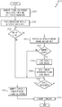
With reference to FIG. 3, GS 108 tasks are described. At 250, trigger logic is generated. The trigger logic comprises multiple trigger logic modules that are generated using A/C specific parameters and user input. At 252 the trigger logic is stored in the trigger logic library 154. If there has not been a receipt of a CDR at 254, and a configuration file (CF) request arrives at 256, then a CF is generated using the files in the trigger logic library 154. At 260, the CF is transmitted.
However, when a CDR is received at 254, then the CDR may be processed with A/C specific parameters and user input at 262 to identify updates to trigger logic modules at 264. At 262 and 264, the user input may be responsive to a technical review of the CDR and A/C specific parameters. The technical review of the CDR and A/C specific parameters may include the GS module 60 further being configured to: identify the trigger; and prompt a technical review of the trigger and associated record of data bus activity. Users, such as engineers and technicians, may perform the technical reviews, identify updates (264), and revise individual trigger logic modules (266). The trigger logic library 154 is continually updated (268) with revised trigger logic modules. Accordingly, the trigger logic library 154 is current, and a request for a configuration file at 256 initiates the generation of a configuration file (258) and transmission of a configuration file (260) that reflects the most recent trigger logic modules.
The referenced users may be platform customers, original equipment manufacturers (OEMs), manufacturers of individual aircraft systems and components, engineers, technicians, and the like. The user input associated with a request for a configuration file at 256 may represent a first user-specific selection of trigger logic modules in the trigger logic library. The user input at 262 (associated with a technical review of the CDR) may or may not be from the same user as the user that provided the user input at 256.
As is readily understandable, with any given group of users, there may be some reused and/or repeatedly used trigger logic modules. For example, a user requesting a first CF may be one of a plurality of users. In this scenario, the method 200 and system 100 are further configured to: receive, from each of the plurality of users, a respective user-specific selection of the trigger logic modules; generate a respective plurality of CF, each CF of the plurality of CF being responsive to a respective one of the user-specific selections of trigger logic modules; and transmit each CF of the plurality of CFs to its respective user. The system and method may further store the plurality of user-specific CF for future analysis. At 264, responsive to identifying a trigger update, the method 200 may revise each CF of the plurality of stored CFs responsive to the revised trigger logic. As mentioned, these updates to the trigger logic library and to the CFs are performed off-platform.
Also mentioned, the trigger system 106 may employ an audio system 132, configured to continuously detect audible emissions and ambient noise in the platform and generate audio data based thereon. In addition to enabling the above described functions, program 22 enables the trigger module 50 to receive and process the audio data to distinguish between spoken commands and ambient cabin noises; and identify the trigger from among either the spoken commands or the ambient cabin noises. As with the previous examples, the trigger module 50 may monitor the audio data to determine (a) that the trigger occurred, and (b) the trigger identity based on processing the audio data with the CF. Accordingly, the trigger logic library 154 may comprise audio trigger logic modules. Audio trigger logic modules comprise trigger identifications associated with various words, phrases, types of sounds, and loudness (decibel) thresholds, and provide associated default record times as described herein.
Additionally, the trigger module 50 may process received user input data to determine that a user has manipulated a user input device 130 to force a trigger. In this scenario, the identified trigger is a user initiated trigger, and again, a predetermined default record time may be employed. In other embodiments, the user may force the trigger, and also force the amount of record time. Responsive thereto, the trigger module 50 records all data bus activity for the required amount of time, and the CDR is generated as before.
Accordingly, the exemplary embodiments discussed above provide a technologically improved method and system to record data during operation of an aircraft 102. A technological benefit of the provided data recording systems and methods is the leaning-out of the onboard software (program 22) by moving bulky and frequently changing software (program 32) to a ground system (GS) 108. Specifically, having the frequently changing software (program 32) reside external to the aircraft 102 means that (i) the trigger logic library 154 may be frequently revised without necessitating recertification of the onboard software (program 22), and (ii) trigger logic modules may be selected and reused on an as-needed basis.
While at least one exemplary embodiment has been presented in the foregoing detailed description of the invention, it should be appreciated that a vast number of variations exist. It should also be appreciated that the exemplary embodiment or exemplary embodiments are only examples, and are not intended to limit the scope, applicability, or configuration of the invention in any way. Rather, the foregoing detailed description will provide those skilled in the art with a convenient road map for implementing an exemplary embodiment of the invention. It being understood that various changes may be made in the function and arrangement of elements described in an exemplary embodiment without departing from the scope of the invention as set forth in the appended claims.

Claims (15)

What is claimed is:
1. A data reporting system for a platform, the system comprising:
a navigation system providing navigation data;
an avionics system providing avionics data;
a trigger module operatively coupled to the navigation system and the avionics system, and configured to process a platform-specific configuration file (CF) during platform operation and generate therefrom a customized data report (CDR); and
a ground station (GS) module external to the platform, the GS module configured to generate the platform-specific configuration file (CF);
and wherein
the trigger module is configured to:
process the avionics data and the navigation data with the CF to:
determine (a) that a trigger occurred, and (b) a trigger identity;
responsive to determining that a trigger occurred, record data bus activity for a duration of time associated with the trigger identity in the CF;
generate the CDR including the record of data bus activity; and
transmit the CDR to the GS module via a wireless communication link; and
the GS module is configured to:
reference trigger logic in a trigger logic library and aircraft (A/C) specific parameters based on a first user input to generate therefrom the platform-specific CF, wherein the trigger logic includes a first plurality of predefined trigger logic modules, each being platform-specific and directed to one or more categories from the set including: safety, engine status, fault detection, and avionic system status; and
transmit the CF to the trigger module via the wireless communication link; and
responsive to receiving the CDR,
(a) process the CDR with a second user input to thereby identify a trigger logic update; (b) update a trigger library with a revised trigger logic; and (c) revise the CF responsive to the revised trigger logic;
wherein the first user input represents a first user-specific selection of trigger logic modules in the trigger logic library, and the second user input is responsive to a technical review of the CDR and A/C specific parameters; and
wherein the GS module is further configured to:
receive, from each of a plurality of users, a respective user-specific selection of the trigger logic modules;
generate a respective plurality of CF responsive to each of the user-specific selections of trigger logic modules; and
store the plurality of user-specific CF.
2. The system of claim 1, wherein the technical review of the CDR and A/C specific parameters comprises the GS module further being configured to identify the trigger.
3. The system of claim 2, wherein the technical review of the CDR and A/C specific parameters comprises the GS module further being configured to prompt a technical review of the trigger and associated record of data bus activity.
4. The system of claim 1, wherein, responsive to identifying a trigger update, the GS module is further configured to revise each CF of the plurality of stored CFs responsive to the revised trigger logic.
5. A data reporting system for a platform, the system comprising:
a navigation system providing navigation data;
an avionics system providing avionics data;
a trigger module operatively coupled to the navigation system and the avionics system, and configured to process a platform-specific configuration file (CF) during platform operation and generate therefrom a customized data report (CDR); and
a ground station (GS) module external to the platform, the GS module configured to generate the platform-specific configuration file (CF);
and wherein
the trigger module is configured to:
process the avionics data and the navigation data with the CF to:
determine (a) that a trigger occurred, and (b) a trigger identity;
responsive to determining that a trigger occurred, record data bus activity for a duration of time associated with the trigger identity in the CF;
generate the CDR including the record of data bus activity; and
transmit the CDR to the GS module via a wireless communication link; and
the GS module is configured to:
reference trigger logic in a trigger logic library and aircraft (A/C) specific parameters based on a first user input to generate therefrom the platform-specific CF, wherein the trigger logic includes a first plurality of predefined trigger logic modules, each being platform-specific and directed to one or more categories from the set including: safety, engine status, fault detection, and avionic system status, and wherein the first user input represents a first user-specific selection of trigger logic modules in the trigger logic library; and
transmit the CF to the trigger module via the wireless communication link; and
responsive to receiving the CDR,
(a) process the CDR with a second user input to thereby identify a trigger logic update; (b) update a trigger library with a revised trigger logic; and (c) revise the CF responsive to the revised trigger logic;
further comprising an audio system configured to continuously detect audible emissions in the platform and generate audio data based thereon, and wherein the trigger module is further configured to determine (a) that the trigger occurred, and (b) the trigger identity based on processing the audio data with the CF.
6. The system of claim 5, wherein the trigger module is further configured to:
process the audio data to distinguish between spoken commands and ambient cabin noises; and
identify the trigger from among either the spoken commands or the ambient cabin noises.
7. A method for data reporting for a platform, the method comprising:
at a trigger module,
receiving navigation data;
receiving avionics data;
processing the avionics data and the navigation data with a platform-specific configuration file (CF) during platform operation to determine (a) whether a trigger occurred, and (b) a trigger identity;
responsive to determining that a trigger occurred, (i) recording data bus activity for a duration of time associated with the trigger identity, (ii) generating a customized data report (CDR) including the record of data bus activity; and (iii) transmitting the CDR to a ground station (GS) module external to the platform, via a wireless communication link; and
at the ground station (GS) module,
referencing trigger logic in a trigger logic library and aircraft (A/C) specific parameters based on a first user input to generate therefrom the platform-specific CF, wherein the first user input represents a first user-specific selection of trigger logic modules in the trigger logic library;
transmitting the CF to the trigger module via the wireless communication link; and
responsive to receiving the CDR,
(a) processing the CDR with a second user input to thereby identify a trigger logic update; and, (b) updating a trigger library with a revised trigger logic;
wherein the trigger logic includes a first plurality of predefined trigger logic modules, each being platform-specific and directed to one or more categories from the set including: safety, engine status, fault detection, and avionic system status.
8. The method of claim 7, wherein the technical review of the CDR and A/C specific parameters comprises, at the GS module, identifying the trigger.
9. The method of claim 8, wherein the technical review of the CDR and A/C specific parameters comprises, at the GS module, prompting a technical review of the trigger and associated record of data bus activity.
10. The method of claim 9, wherein the second user input is responsive to a technical review of the CDR and A/C specific parameters.
11. The method of claim 10, further comprising, at the GS module:
receiving, from each of a plurality of users, a respective user-specific selection of the trigger logic modules; and
generating a respective plurality of CF responsive to each of the user-specific selections of trigger logic modules.
12. The method of claim 11, further comprising:
at the GS module,
storing the plurality of user-specific CF; and
responsive to identifying a trigger update, revising each CF of the plurality of stored CFs responsive to the revised trigger logic.
13. The method of claim 12, further comprising:
at the trigger module,
continuously detecting audible emissions in the platform, and generating audio data based thereon; and
determining, based on processing the audio data with the CF, (a) that the trigger occurred, and (b) the trigger identity.
14. The method of claim 13, further comprising, at the trigger module:
processing the audio data to distinguish between spoken commands and ambient cabin noises; and
identifying the trigger from among either the spoken commands or the ambient cabin noises.
15. A method for data reporting for an aircraft, the method comprising:
at a ground station (GS) module external to the aircraft,
creating a trigger library comprising multiple trigger logic modules based on a first user input and aircraft specific parameters, the trigger logic modules each being platform-specific and directed to one or more categories from the set including: safety, engine status, fault detection, and avionic system status;
generating an aircraft-specific configuration file (CF) based on a second user input and the trigger logic library; and
transmitting the CF to a trigger module in the aircraft via a wireless communication link; and
at the trigger module,
receiving the platform-specific configuration file (CF);
receiving navigation data, avionics data, and sensor system data;
processing the avionics data, the navigation data, and the sensor system data with the (CF) during aircraft operation to monitor for triggers;
determining (a) that a trigger occurred, and (b) a trigger identity; and
responsive to determining that the trigger occurred, (i) recording data bus activity for a duration of time associated with the trigger identity, (ii) generating a customized data report (CDR) including the record of data bus activity; and (iii) transmitting the CDR to the GS module; and
further comprising, at the GS module:
receiving, from each of a plurality of users, a respective user-specific selection of the trigger logic modules; and
generating a respective plurality of CF, each CF of the plurality of CF being responsive to a respective one of the user-specific selections of trigger logic modules.
US15/878,676 2018-01-24 2018-01-24 Method and system for data reporting using customized triggers Active 2038-10-06 US10748359B2 (en)

Priority Applications (2)

Application Number Priority Date Filing Date Title
US15/878,676 US10748359B2 (en) 2018-01-24 2018-01-24 Method and system for data reporting using customized triggers
EP19152418.0A EP3518185A1 (en) 2018-01-24 2019-01-17 Method and system for data reporting using customized triggers

Applications Claiming Priority (1)

Application Number Priority Date Filing Date Title
US15/878,676 US10748359B2 (en) 2018-01-24 2018-01-24 Method and system for data reporting using customized triggers

Publications (2)

Publication Number Publication Date
US20190228599A1 US20190228599A1 (en) 2019-07-25
US10748359B2 true US10748359B2 (en) 2020-08-18

Family

ID=65036733

Family Applications (1)

Application Number Title Priority Date Filing Date
US15/878,676 Active 2038-10-06 US10748359B2 (en) 2018-01-24 2018-01-24 Method and system for data reporting using customized triggers

Country Status (2)

Country Link
US (1) US10748359B2 (en)
EP (1) EP3518185A1 (en)

Families Citing this family (2)

* Cited by examiner, † Cited by third party
Publication number Priority date Publication date Assignee Title
CN112433901A (en) * 2020-12-04 2021-03-02 昆易电子科技(上海)有限公司 Method and system for vehicle bus triggering function test
US20230391470A1 (en) * 2022-06-01 2023-12-07 Arinc Incorporated Onboard equipment data synchronization system

Citations (20)

* Cited by examiner, † Cited by third party
Publication number Priority date Publication date Assignee Title
US20020113720A1 (en) * 2001-02-22 2002-08-22 Ara Derderian System and method for automatically triggering events shown on aircraft displays
US7912592B2 (en) * 2006-06-09 2011-03-22 Garmin International, Inc. Automatic speech recognition system and method for aircraft
EP2348488A1 (en) 2010-01-25 2011-07-27 United Technologies Corporation Method and system for exposing and recording embedded avionics data
US20130197725A1 (en) * 2012-01-31 2013-08-01 Gulfstream Aerospace Corporation Methods and systems for requesting and retrieving aircraft data during flight of an aircraft
US20150327307A1 (en) * 2014-05-07 2015-11-12 Airbus Operations (S.A.S.) System for connecting a mobile device to a wireless network of an aircraft
US20160071335A1 (en) * 2014-09-10 2016-03-10 The Boeing Company Configurable Onboard Information Processing
US9346557B2 (en) * 2012-04-16 2016-05-24 Flight Data Services Limited Flight data monitoring and validation
US20160233948A1 (en) 2015-02-06 2016-08-11 Airbus (S.A.S.) Device, system and method to assist with aircraft maintenance
US20160318622A1 (en) * 2015-04-29 2016-11-03 Rosemount Aerospace Inc. Aircraft operational anomaly detection
US20170063944A1 (en) 2015-08-27 2017-03-02 The Boeing Company Flight Data Recorder Streaming (FDRS) Solution
US20170063995A1 (en) * 2015-08-31 2017-03-02 The Boeing Company Method for providing flight management system data to peripheral devices
US9620020B2 (en) 2015-08-06 2017-04-11 Honeywell International Inc. Communication-based monitoring of compliance with aviation regulations and operating procedures
EP3156977A1 (en) 2015-10-12 2017-04-19 Honeywell International Inc. Method and system for using combined voice and customized instructions to trigger vehicle reports
US9738398B1 (en) * 2017-01-27 2017-08-22 Comac America Corporation Ejectable flight data recorder systems, methods, and devices
US20170241798A1 (en) * 2014-09-16 2017-08-24 Aviovision System for calculating aircraft performance and method for performing the same
US9746851B2 (en) 2013-05-22 2017-08-29 Air China Limited Apparatus and method for testing aircraft message trigger logics
US20170263135A1 (en) 2016-03-14 2017-09-14 Ehsan Rezaei Gerovi Analyzer systematic and reducing human faults system in aircraft flight
US20170301247A1 (en) 2016-04-19 2017-10-19 George Mason University Method And Apparatus For Probabilistic Alerting Of Aircraft Unstabilized Approaches Using Big Data
US20170313425A1 (en) * 2016-04-28 2017-11-02 Dassault Aviation Avionics system for assisting implementation of security measures onboard an aircraft, aircraft comprising such a system, and associated method
US20170324437A1 (en) 2016-04-22 2017-11-09 James J. Ruttler Smart aviation communication headset and peripheral components

Patent Citations (20)

* Cited by examiner, † Cited by third party
Publication number Priority date Publication date Assignee Title
US20020113720A1 (en) * 2001-02-22 2002-08-22 Ara Derderian System and method for automatically triggering events shown on aircraft displays
US7912592B2 (en) * 2006-06-09 2011-03-22 Garmin International, Inc. Automatic speech recognition system and method for aircraft
EP2348488A1 (en) 2010-01-25 2011-07-27 United Technologies Corporation Method and system for exposing and recording embedded avionics data
US20130197725A1 (en) * 2012-01-31 2013-08-01 Gulfstream Aerospace Corporation Methods and systems for requesting and retrieving aircraft data during flight of an aircraft
US9346557B2 (en) * 2012-04-16 2016-05-24 Flight Data Services Limited Flight data monitoring and validation
US9746851B2 (en) 2013-05-22 2017-08-29 Air China Limited Apparatus and method for testing aircraft message trigger logics
US20150327307A1 (en) * 2014-05-07 2015-11-12 Airbus Operations (S.A.S.) System for connecting a mobile device to a wireless network of an aircraft
US20160071335A1 (en) * 2014-09-10 2016-03-10 The Boeing Company Configurable Onboard Information Processing
US20170241798A1 (en) * 2014-09-16 2017-08-24 Aviovision System for calculating aircraft performance and method for performing the same
US20160233948A1 (en) 2015-02-06 2016-08-11 Airbus (S.A.S.) Device, system and method to assist with aircraft maintenance
US20160318622A1 (en) * 2015-04-29 2016-11-03 Rosemount Aerospace Inc. Aircraft operational anomaly detection
US9620020B2 (en) 2015-08-06 2017-04-11 Honeywell International Inc. Communication-based monitoring of compliance with aviation regulations and operating procedures
US20170063944A1 (en) 2015-08-27 2017-03-02 The Boeing Company Flight Data Recorder Streaming (FDRS) Solution
US20170063995A1 (en) * 2015-08-31 2017-03-02 The Boeing Company Method for providing flight management system data to peripheral devices
EP3156977A1 (en) 2015-10-12 2017-04-19 Honeywell International Inc. Method and system for using combined voice and customized instructions to trigger vehicle reports
US20170263135A1 (en) 2016-03-14 2017-09-14 Ehsan Rezaei Gerovi Analyzer systematic and reducing human faults system in aircraft flight
US20170301247A1 (en) 2016-04-19 2017-10-19 George Mason University Method And Apparatus For Probabilistic Alerting Of Aircraft Unstabilized Approaches Using Big Data
US20170324437A1 (en) 2016-04-22 2017-11-09 James J. Ruttler Smart aviation communication headset and peripheral components
US20170313425A1 (en) * 2016-04-28 2017-11-02 Dassault Aviation Avionics system for assisting implementation of security measures onboard an aircraft, aircraft comprising such a system, and associated method
US9738398B1 (en) * 2017-01-27 2017-08-22 Comac America Corporation Ejectable flight data recorder systems, methods, and devices

Non-Patent Citations (1)

* Cited by examiner, † Cited by third party
Title
InFlight Labs, Llc, "InFlight Labs New "Smart Emergency Location Transmitter" Tracks Any Missing Aircraft with "One Touch" From ATC Command," China Weekly News [Atlanta], Apr. 28, 2015.

Also Published As

Publication number Publication date
EP3518185A1 (en) 2019-07-31
US20190228599A1 (en) 2019-07-25

Similar Documents

Publication Publication Date Title
CN106952504B (en) Aircraft system with enhanced CPDLC message management
EP3296831B1 (en) Methods and systems for automation guidance
US8977482B2 (en) Method and apparatus for generating flight-optimizing trajectories
EP3288006B1 (en) Community noise management with aircraft dynamic path variation
US10971155B2 (en) Aircraft systems and methods for monitoring onboard communications
US11270593B2 (en) Advisory method and system for flight trajectory optimization
US9916765B2 (en) Aircraft systems and methods for providing landing approach alerts
US10762793B2 (en) Systems and methods for selecting accurate runway records for use in cockpit display systems
US10290217B1 (en) Systems and methods for evaluation of runway changes
US11043131B2 (en) Systems and methods for generating a recapture path for an aircraft
US11299285B2 (en) Systems and methods for providing throttle guidance as a function of flight path acceleration
US11586196B2 (en) Approach mode activation monitoring function and automatic activation in an event of pilot incapacitation
US11275388B2 (en) Systems and methods for an enhanced stable approach monitor
US10515554B1 (en) Systems and methods for time-based viewing of predicted clearance requests
US10748359B2 (en) Method and system for data reporting using customized triggers
US10417919B1 (en) Systems and methods for optimizing landing performance
US10565886B2 (en) Systems and methods for predicting loss of separation events
US20230215278A1 (en) Systems and methods for adding relevant data to atc transcription messages
US20230074014A1 (en) Systems and methods for transcribing and analyzing broadcast messages in an aircraft
US20220388674A1 (en) Methods and systems for alerting dynamic changes in flight rules
EP3855269A1 (en) Approach mode activation monitoring function and automatic activation in an event of pilot incapacitation
US11288968B2 (en) Method and apparatus to switch between multiple formats of runway surface conditions to compute required runway distances
US11587447B2 (en) Dynamically modifiable parameters in required time of arrival (RTA) regions of an assigned flight path
US20230093956A1 (en) Systems and methods for alerting when an intruder trend vector is predicted to intercept with an aircraft taxi path
EP4160572A1 (en) Systems and methods for alerting when an intruder trend vector is predicted to intercept with an aircraft taxi path

Legal Events

Date Code Title Description
AS Assignment

Owner name: HONEYWELL INTERNATIONAL INC., NEW JERSEY

Free format text: ASSIGNMENT OF ASSIGNORS INTEREST;ASSIGNORS:HRIB, DALIBOR;KUTAL, ONDREJ;KADLAS, JAKUB;REEL/FRAME:044713/0884

Effective date: 20180124

FEPP Fee payment procedure

Free format text: ENTITY STATUS SET TO UNDISCOUNTED (ORIGINAL EVENT CODE: BIG.); ENTITY STATUS OF PATENT OWNER: LARGE ENTITY

STPP Information on status: patent application and granting procedure in general

Free format text: NON FINAL ACTION MAILED

STPP Information on status: patent application and granting procedure in general

Free format text: NOTICE OF ALLOWANCE MAILED -- APPLICATION RECEIVED IN OFFICE OF PUBLICATIONS

STCF Information on status: patent grant

Free format text: PATENTED CASE

MAFP Maintenance fee payment

Free format text: PAYMENT OF MAINTENANCE FEE, 4TH YEAR, LARGE ENTITY (ORIGINAL EVENT CODE: M1551); ENTITY STATUS OF PATENT OWNER: LARGE ENTITY

Year of fee payment: 4