US10746312B2 - Single fill valve - Google Patents
Single fill valve Download PDFInfo
- Publication number
- US10746312B2 US10746312B2 US16/125,825 US201816125825A US10746312B2 US 10746312 B2 US10746312 B2 US 10746312B2 US 201816125825 A US201816125825 A US 201816125825A US 10746312 B2 US10746312 B2 US 10746312B2
- Authority
- US
- United States
- Prior art keywords
- cryogenic liquid
- valve
- storage vessel
- liquid storage
- gas
- Prior art date
- Legal status (The legal status is an assumption and is not a legal conclusion. Google has not performed a legal analysis and makes no representation as to the accuracy of the status listed.)
- Active
Links
- 239000007788 liquid Substances 0.000 claims abstract description 80
- 230000008878 coupling Effects 0.000 claims description 6
- 238000010168 coupling process Methods 0.000 claims description 6
- 238000005859 coupling reaction Methods 0.000 claims description 6
- 238000011282 treatment Methods 0.000 description 25
- 238000001816 cooling Methods 0.000 description 9
- 239000000463 material Substances 0.000 description 8
- 238000000034 method Methods 0.000 description 5
- 239000012530 fluid Substances 0.000 description 4
- 230000006378 damage Effects 0.000 description 3
- 239000012535 impurity Substances 0.000 description 3
- 230000000903 blocking effect Effects 0.000 description 2
- 239000002537 cosmetic Substances 0.000 description 2
- 206010020751 Hypersensitivity Diseases 0.000 description 1
- 208000027418 Wounds and injury Diseases 0.000 description 1
- 208000026935 allergic disease Diseases 0.000 description 1
- 230000007815 allergy Effects 0.000 description 1
- 230000009286 beneficial effect Effects 0.000 description 1
- 230000015572 biosynthetic process Effects 0.000 description 1
- 238000002485 combustion reaction Methods 0.000 description 1
- 239000000356 contaminant Substances 0.000 description 1
- 239000004078 cryogenic material Substances 0.000 description 1
- 230000000593 degrading effect Effects 0.000 description 1
- 230000000994 depressogenic effect Effects 0.000 description 1
- 238000005516 engineering process Methods 0.000 description 1
- 239000000945 filler Substances 0.000 description 1
- 208000014674 injury Diseases 0.000 description 1
- 230000007794 irritation Effects 0.000 description 1
- 238000012986 modification Methods 0.000 description 1
- 230000004048 modification Effects 0.000 description 1
- 238000003825 pressing Methods 0.000 description 1
- 230000001681 protective effect Effects 0.000 description 1
- 238000007789 sealing Methods 0.000 description 1
- 239000007921 spray Substances 0.000 description 1
- 239000000126 substance Substances 0.000 description 1
- 238000002604 ultrasonography Methods 0.000 description 1
Images


Classifications
-
- F—MECHANICAL ENGINEERING; LIGHTING; HEATING; WEAPONS; BLASTING
- F16—ENGINEERING ELEMENTS AND UNITS; GENERAL MEASURES FOR PRODUCING AND MAINTAINING EFFECTIVE FUNCTIONING OF MACHINES OR INSTALLATIONS; THERMAL INSULATION IN GENERAL
- F16K—VALVES; TAPS; COCKS; ACTUATING-FLOATS; DEVICES FOR VENTING OR AERATING
- F16K17/00—Safety valves; Equalising valves, e.g. pressure relief valves
- F16K17/02—Safety valves; Equalising valves, e.g. pressure relief valves opening on surplus pressure on one side; closing on insufficient pressure on one side
- F16K17/14—Safety valves; Equalising valves, e.g. pressure relief valves opening on surplus pressure on one side; closing on insufficient pressure on one side with fracturing member
- F16K17/16—Safety valves; Equalising valves, e.g. pressure relief valves opening on surplus pressure on one side; closing on insufficient pressure on one side with fracturing member with fracturing diaphragm ; Rupture discs
-
- F—MECHANICAL ENGINEERING; LIGHTING; HEATING; WEAPONS; BLASTING
- F16—ENGINEERING ELEMENTS AND UNITS; GENERAL MEASURES FOR PRODUCING AND MAINTAINING EFFECTIVE FUNCTIONING OF MACHINES OR INSTALLATIONS; THERMAL INSULATION IN GENERAL
- F16K—VALVES; TAPS; COCKS; ACTUATING-FLOATS; DEVICES FOR VENTING OR AERATING
- F16K17/00—Safety valves; Equalising valves, e.g. pressure relief valves
- F16K17/40—Safety valves; Equalising valves, e.g. pressure relief valves with a fracturing member, e.g. fracturing diaphragm, glass, fusible joint
-
- F—MECHANICAL ENGINEERING; LIGHTING; HEATING; WEAPONS; BLASTING
- F16—ENGINEERING ELEMENTS AND UNITS; GENERAL MEASURES FOR PRODUCING AND MAINTAINING EFFECTIVE FUNCTIONING OF MACHINES OR INSTALLATIONS; THERMAL INSULATION IN GENERAL
- F16K—VALVES; TAPS; COCKS; ACTUATING-FLOATS; DEVICES FOR VENTING OR AERATING
- F16K1/00—Lift valves or globe valves, i.e. cut-off apparatus with closure members having at least a component of their opening and closing motion perpendicular to the closing faces
- F16K1/14—Lift valves or globe valves, i.e. cut-off apparatus with closure members having at least a component of their opening and closing motion perpendicular to the closing faces with ball-shaped valve member
-
- F—MECHANICAL ENGINEERING; LIGHTING; HEATING; WEAPONS; BLASTING
- F16—ENGINEERING ELEMENTS AND UNITS; GENERAL MEASURES FOR PRODUCING AND MAINTAINING EFFECTIVE FUNCTIONING OF MACHINES OR INSTALLATIONS; THERMAL INSULATION IN GENERAL
- F16K—VALVES; TAPS; COCKS; ACTUATING-FLOATS; DEVICES FOR VENTING OR AERATING
- F16K1/00—Lift valves or globe valves, i.e. cut-off apparatus with closure members having at least a component of their opening and closing motion perpendicular to the closing faces
- F16K1/30—Lift valves or globe valves, i.e. cut-off apparatus with closure members having at least a component of their opening and closing motion perpendicular to the closing faces specially adapted for pressure containers
- F16K1/301—Lift valves or globe valves, i.e. cut-off apparatus with closure members having at least a component of their opening and closing motion perpendicular to the closing faces specially adapted for pressure containers only shut-off valves, i.e. valves without additional means
- F16K1/303—Lift valves or globe valves, i.e. cut-off apparatus with closure members having at least a component of their opening and closing motion perpendicular to the closing faces specially adapted for pressure containers only shut-off valves, i.e. valves without additional means with a valve member, e.g. stem or shaft, passing through the seat
-
- F—MECHANICAL ENGINEERING; LIGHTING; HEATING; WEAPONS; BLASTING
- F16—ENGINEERING ELEMENTS AND UNITS; GENERAL MEASURES FOR PRODUCING AND MAINTAINING EFFECTIVE FUNCTIONING OF MACHINES OR INSTALLATIONS; THERMAL INSULATION IN GENERAL
- F16K—VALVES; TAPS; COCKS; ACTUATING-FLOATS; DEVICES FOR VENTING OR AERATING
- F16K1/00—Lift valves or globe valves, i.e. cut-off apparatus with closure members having at least a component of their opening and closing motion perpendicular to the closing faces
- F16K1/30—Lift valves or globe valves, i.e. cut-off apparatus with closure members having at least a component of their opening and closing motion perpendicular to the closing faces specially adapted for pressure containers
- F16K1/307—Additional means used in combination with the main valve
Definitions
- This invention relates to a valve for use with vessels that store and dispense liquids. More specifically, this invention relates to vessels that store and dispense cryogenic liquids for use in medical and cosmetics applications.
- the single fill valve is intended to prevent refilling of the storage vessel after a first fill of the vessel.
- skin treatment systems include vessels filled with a substance that could be used as a skin cooling material.
- the skin cooling material can be packed in cartridges, cylinders, canisters and other similar products.
- Such cylinders or canisters are typically installed by the user and may be removed and replaced by the user, when the skin cooling material in the vessel is depleted.
- Candela skin treatment systems incorporate a Dynamic Cooling Device (DCD) used to provide skin protection and palliative relief during aesthetic skin treatment procedures.
- DCD Dynamic Cooling Device
- Such systems deposit a user selectable amount of cryogen spray prior to, during, or after the aesthetic skin treatment so as to provide these beneficial effects.
- Cryogen a liquefied gas is usually stored in a vessel under pressure so that it can be delivered to the treated skin segment in liquid or gaseous state.
- each of the materials used for skin treatment is a specially formulated and/or certified material.
- the cryogen content of the vessel has to be maintained at a high level of purity. Impurities could result in any or all of the following: patient irritation, allergy and combustion of impurities during the skin treatment procedure. The impurities could also clog the skin cooling material delivery system and restrict flow of the cooling material degrading efficiency of the cooling required for skin treatment procedure.
- non-certified cryogenic liquid The price of a non-certified cryogenic liquid is usually lower than the price of the specially formulated and certified cryogenic liquid. Users of cooling systems could be tempted to use these lower cost, non-certified cryogenic liquids, at least some of the time, especially when cryogenic fluid vessels are depleted. Notwithstanding safety issues, this savings in cost is quickly lost when the skin treatment delivery system needs to be replaced because of a clogged skin cooling material delivery system or there is injury to the patient.
- Pressurized liquid storage vessels are typically used in apparatuses that require continuous or pulsed supply of cryogenic fluid or gas.
- these vessels filled by the cryogenic fluid or gas contain an amount of cryogenic fluid sufficient for multiple discharges and refills.
- This typically requires the vessel to be associated with a mechanism allowing connecting and disconnecting gas flow between the vessel and the skin treatment apparatuses.
- Such mechanism could be a valve that supports filling of the vessel by the cryogenic liquid and discharge of the cryogenic liquid from the vessel.
- the valve operates in an open state when mounted to the apparatus, and closed state when dismounted from the apparatus.
- the valve is typically designed to allow many mounts and dismounts to the apparatus.
- a second value further downstream is used to precisely meter and time the discharge of liquid to skin during laser delivery procedures.
- the vessels or canisters and valves associated with them are designed and manufactured for multiple canister refilling cycles. Accordingly, the valves are designed and manufactured, to permit a user to disconnect the canister from the apparatus for refilling, and reconnect when necessary. As explained above such refilling of vessels is not acceptable for skin treatment applications since delivery of non-certified cryogenic liquid cannot be avoided and can cause damage to the patient and/or apparatus.
- the terms “vessel”, “cylinder” and “canister”, have the same meaning, are used interchangeably and designate objects capable of storing a liquid and in particular a cryogenic liquid.
- skin treatment system includes any skin treatment apparatus including apparatuses for aesthetic skin treatment applying to the skin light energy, radio frequency (RF) energy or ultrasound energy and a combination of the above treatment energies.
- RF radio frequency
- valve as used in the present document includes any apparatus for controlling the flow of liquid into or out of a vessel.
- the present valve is a single fill valve for use with vessels or canisters that store and dispense liquids and in particular cryogenic liquid storage vessels that store and dispense cryogenic liquids for use in medical and cosmetics applications.
- the cryogenic liquid is used to cool the skin in aesthetic skin treatment procedures.
- the single fill valve includes a central opening configured to receive a cryogenic liquid and a distal opening configured to direct cryogenic liquid into a cryogenic liquid storage vessel.
- the single fill valve further includes a plunger and a pin configured to move the plunger, to block at least the distal opening of the single fill valve upon completion of the cryogenic liquid storage vessel being filled with the cryogenic liquid. Blocking of the distal opening of the single use fill valve prevents refilling of the storage vessel with cryogenic other liquid.
- the single use fill valve includes on one end a coupling arrangement configured to couple to a cryogenic liquid storage vessel and on other end a coupling arrangement configured to couple to a cryogenic liquid filling station or a skin treatment apparatus.
- the single fill valve also includes some safety features preventing formation of excessive pressure inside the cryogenic liquid storage vessel.
- FIG. 1 is a cross section of an example of a single fill valve for a cryogenic liquid storage vessel
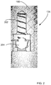
- FIG. 2 is an example of a one-way ball valve
- FIG. 3 is an example of a protective over pressure value for releasing over pressured vessels in a safe and controlled manner.
- FIG. 1 is a cross section of an example of a single fill valve for a cryogenic liquid storage vessel.
- Valve 100 is shown attached to a cryogenic liquid storage vessel 104 .
- Valve 100 is a tube-like cylindrical body that includes a proximal end 108 and a distal end 112 . Both ends 108 and 112 are terminated by a coupling arrangement.
- the coupling arrangement could be a thread implemented on outer side of the tube-like cylindrical body.
- Threaded segment 108 is located at a proximal end of valve 100 and configured to facilitate connection of single use valve 100 to a cryogenic liquid filling station (not shown). Threaded segment 112 located distal to liquid filling station end of valve 100 facilitates connection of single use valve 100 to a cryogenic liquid storage vessel 104 .
- sealing element 118 is pressed by cylindrical insert 130 to support hermetic connection between the valve 100 and the cryogenic liquid filling station or the skin treatment apparatus.
- liquid or gas 120 When connected to a cryogenic liquid filling station single use valve 100 , allows the liquid or gas 120 to enter the inner space or volume 114 of vessel 104 through normal center fill port 110 .
- Liquid or gas 120 flows from center fill port 110 into liquid storage vessel 104 through a distal side fill port 124 and bottom fill port 126 .
- Pin 128 is in mechanical contact with a plunger 132 .
- inflow passage 122 of side fill port 124 is open allowing the cryogenic liquid or gas to fill vessel 104 via distal side fill port 124 and distal bottom fill port 126 .
- pin 128 Upon completion of filling vessel 104 with cryogenic liquid filling or other liquid, pin 128 is pushed in the direction of/into the vessel 104 . Depressed pin 128 , displaces plunger 132 blocking inflow passage 122 preventing liquid or gas 120 from entering liquid storage vessel 104 .
- Pushing of the pin can be manually done after completion of the cylinder filling, or can be automated, occurring when releasing filled canister from the liquid filling station or when the filled canister is first connected to the tissue treatment system.
- Manual pushing of the pin can be done using a special tool designed for this purpose, and such tool can be designed into the liquid refilling station vessel coupler so that the pin 128 can be pushed into place prior to disconnecting the coupler from the vessel.
- cryogenic liquid in the cryogenic liquid storage vessel 104 is maintained under pressure such that when cryogenic liquid storage vessel 104 is connected to a skin treatment apparatus and skin treatment is conducted the liquid can be dispensed and cool the treated area of the skin.
- cryogenic liquid or gas exits cryogenic liquid storage vessel 104 through a one-way ball valve 136 shown in detail in FIG. 2 .
- Spring 202 maintains the desired position of ball 204 .
- Valve 100 includes some safety features shown in FIG. 3 . In case of emergency these features would support safe liquid discharge from the cryogenic liquid storage vessel 104 .
- Burst disk 304 held by nut 306 is a thin (0.05-0.2 mm) diaphragm that acts as a safety pressure release mechanism.
- Channel 308 communicates with the inner space or volume 114 of vessel 104 and maintains the cryogenic liquid pressure in inner space or volume 114 by applying pressure to burst disk 304 . Excessive cryogenic liquid pressure will destroy disk 304 and reduce pressure in the inner space 114 .
Landscapes
- Engineering & Computer Science (AREA)
- General Engineering & Computer Science (AREA)
- Mechanical Engineering (AREA)
- Surgical Instruments (AREA)
- Thermotherapy And Cooling Therapy Devices (AREA)
Abstract
Description
Claims (8)
Priority Applications (1)
| Application Number | Priority Date | Filing Date | Title |
|---|---|---|---|
| US16/125,825 US10746312B2 (en) | 2018-09-10 | 2018-09-10 | Single fill valve |
Applications Claiming Priority (1)
| Application Number | Priority Date | Filing Date | Title |
|---|---|---|---|
| US16/125,825 US10746312B2 (en) | 2018-09-10 | 2018-09-10 | Single fill valve |
Publications (2)
| Publication Number | Publication Date |
|---|---|
| US20200080655A1 US20200080655A1 (en) | 2020-03-12 |
| US10746312B2 true US10746312B2 (en) | 2020-08-18 |
Family
ID=69720629
Family Applications (1)
| Application Number | Title | Priority Date | Filing Date |
|---|---|---|---|
| US16/125,825 Active US10746312B2 (en) | 2018-09-10 | 2018-09-10 | Single fill valve |
Country Status (1)
| Country | Link |
|---|---|
| US (1) | US10746312B2 (en) |
Citations (12)
| Publication number | Priority date | Publication date | Assignee | Title |
|---|---|---|---|---|
| US2524052A (en) * | 1946-09-23 | 1950-10-03 | Specialties Dev Corp | Valve |
| US3595445A (en) | 1969-01-27 | 1971-07-27 | Rayford Ind Inc | Fluid-dispensing valve |
| US3645291A (en) | 1968-05-06 | 1972-02-29 | Nitrochill Ltd | Cryogenic filling valve |
| US8316873B2 (en) | 2005-12-30 | 2012-11-27 | Nanospace Ab | Single use valve |
| US8720858B2 (en) | 2008-09-05 | 2014-05-13 | Sartorius StedimBioteen GmbH | Single use, disposable diaphragm valve in which the valve body and sealing membrane are welded to one another |
| US20160053915A1 (en) | 2013-04-03 | 2016-02-25 | Sicpa Holding Sa | Single use valves |
| US20160186891A1 (en) | 2014-12-24 | 2016-06-30 | Cameron International Corporation | Valve assembly |
| US20170008752A1 (en) | 2012-03-07 | 2017-01-12 | Ge Healthcare Bio-Sciences Corp. | Disposable valve and flexible containers for pressurized bioreactors |
| US20170014174A1 (en) | 2015-07-17 | 2017-01-19 | Candela Corporation | Cryogenic Cylinder |
| US9605789B2 (en) | 2013-09-13 | 2017-03-28 | Biofilm Ip, Llc | Magneto-cryogenic valves, systems and methods for modulating flow in a conduit |
| US9702505B2 (en) | 2013-03-15 | 2017-07-11 | Worthington Cylinders Corp. | Cryogenic fluid cylinder |
| US20170354451A1 (en) | 2015-01-13 | 2017-12-14 | Cryobeauty | Method and device for cosmetically treating dark spots on the skin by means of cryo-cyto-selective cryogenics |
Family Cites Families (1)
| Publication number | Priority date | Publication date | Assignee | Title |
|---|---|---|---|---|
| US9506577B2 (en) * | 2013-04-30 | 2016-11-29 | Tilden C. Harris | Safety valve device |
-
2018
- 2018-09-10 US US16/125,825 patent/US10746312B2/en active Active
Patent Citations (12)
| Publication number | Priority date | Publication date | Assignee | Title |
|---|---|---|---|---|
| US2524052A (en) * | 1946-09-23 | 1950-10-03 | Specialties Dev Corp | Valve |
| US3645291A (en) | 1968-05-06 | 1972-02-29 | Nitrochill Ltd | Cryogenic filling valve |
| US3595445A (en) | 1969-01-27 | 1971-07-27 | Rayford Ind Inc | Fluid-dispensing valve |
| US8316873B2 (en) | 2005-12-30 | 2012-11-27 | Nanospace Ab | Single use valve |
| US8720858B2 (en) | 2008-09-05 | 2014-05-13 | Sartorius StedimBioteen GmbH | Single use, disposable diaphragm valve in which the valve body and sealing membrane are welded to one another |
| US20170008752A1 (en) | 2012-03-07 | 2017-01-12 | Ge Healthcare Bio-Sciences Corp. | Disposable valve and flexible containers for pressurized bioreactors |
| US9702505B2 (en) | 2013-03-15 | 2017-07-11 | Worthington Cylinders Corp. | Cryogenic fluid cylinder |
| US20160053915A1 (en) | 2013-04-03 | 2016-02-25 | Sicpa Holding Sa | Single use valves |
| US9605789B2 (en) | 2013-09-13 | 2017-03-28 | Biofilm Ip, Llc | Magneto-cryogenic valves, systems and methods for modulating flow in a conduit |
| US20160186891A1 (en) | 2014-12-24 | 2016-06-30 | Cameron International Corporation | Valve assembly |
| US20170354451A1 (en) | 2015-01-13 | 2017-12-14 | Cryobeauty | Method and device for cosmetically treating dark spots on the skin by means of cryo-cyto-selective cryogenics |
| US20170014174A1 (en) | 2015-07-17 | 2017-01-19 | Candela Corporation | Cryogenic Cylinder |
Also Published As
| Publication number | Publication date |
|---|---|
| US20200080655A1 (en) | 2020-03-12 |
Similar Documents
| Publication | Publication Date | Title |
|---|---|---|
| US4376376A (en) | Cryogenic device operable in single or dual phase with a range of nozzle sizes and method of using the same | |
| KR960001236B1 (en) | Apparatus for delivering a predetermined amount of a pressurized | |
| EP2596277B1 (en) | Closure device | |
| US5113905A (en) | Carbon dioxide fill manifold and method | |
| RU2407682C2 (en) | One-way valve system sealed over entire surface and fluid feed system | |
| EP1316754A1 (en) | High flow pressurized cryogenic fluid dispensing system | |
| JPH01141285A (en) | High-pressure regulating valve | |
| EP2765296A1 (en) | Integrated cryogenic fluid delivery system | |
| US8210169B2 (en) | Dosing safety arrangement in a delivery apparatus for pressurized medical liquids | |
| US20180193855A1 (en) | Device for discharging fluids | |
| US20200360070A1 (en) | Portable electro-mechanical cryosurgical device | |
| ES2764132T3 (en) | Device for the administration of a corresponding cosmetic product, procedure, use and packaging | |
| CN103002937B (en) | Gas dispenser for dispensing accurate doses of therapeutic gas from a reservoir containing highly compressed therapeutics gas | |
| US6047865A (en) | Gas capsule and gas delivery system | |
| EP3655074B1 (en) | Dispensing system for use in cryogenic skin treatment | |
| US10746312B2 (en) | Single fill valve | |
| PL181661B1 (en) | Gas supplying system | |
| US2078567A (en) | Oxygen emergency apparatus | |
| JP2023543166A (en) | medical device pressure valve | |
| EP3897428B1 (en) | Flow modulation device for dispensing pressurized fluids | |
| ES1141665U (en) | Device for the administration of a cosmetic product (Machine-translation by Google Translate, not legally binding) | |
| US11918960B2 (en) | System and method for dosing wine barrels with sulfur dioxide gas | |
| RU2414269C1 (en) | Knapsack fire extinguisher | |
| JPH08206552A (en) | Pressure accumulation type atomizer | |
| KR20230074173A (en) | Pressure Relief for Medical Devices |
Legal Events
| Date | Code | Title | Description |
|---|---|---|---|
| FEPP | Fee payment procedure |
Free format text: ENTITY STATUS SET TO UNDISCOUNTED (ORIGINAL EVENT CODE: BIG.); ENTITY STATUS OF PATENT OWNER: LARGE ENTITY |
|
| AS | Assignment |
Owner name: CANDELA CORPORATION, MASSACHUSETTS Free format text: ASSIGNMENT OF ASSIGNORS INTEREST;ASSIGNORS:DUBITSKY, DIMA;BARENBOYM, MICHAEL;SCHIRDUAN, OWEN;REEL/FRAME:046888/0014 Effective date: 20180914 |
|
| STPP | Information on status: patent application and granting procedure in general |
Free format text: NOTICE OF ALLOWANCE MAILED -- APPLICATION RECEIVED IN OFFICE OF PUBLICATIONS |
|
| STPP | Information on status: patent application and granting procedure in general |
Free format text: PUBLICATIONS -- ISSUE FEE PAYMENT VERIFIED |
|
| STCF | Information on status: patent grant |
Free format text: PATENTED CASE |
|
| AS | Assignment |
Owner name: BARCLAYS BANK PLC, AS COLLATERAL AGENT, NEW YORK Free format text: SECURITY AGREEMENT;ASSIGNORS:CANDELA CORPORATION;SYNERON MEDICAL LTD.;REEL/FRAME:059593/0269 Effective date: 20220401 |
|
| MAFP | Maintenance fee payment |
Free format text: PAYMENT OF MAINTENANCE FEE, 4TH YEAR, LARGE ENTITY (ORIGINAL EVENT CODE: M1551); ENTITY STATUS OF PATENT OWNER: LARGE ENTITY Year of fee payment: 4 |