US10742048B2 - Wearable electronic device with a caseback having multiple, arc-shaped, ferrous, metal contacts - Google Patents
Wearable electronic device with a caseback having multiple, arc-shaped, ferrous, metal contacts Download PDFInfo
- Publication number
- US10742048B2 US10742048B2 US16/053,545 US201816053545A US10742048B2 US 10742048 B2 US10742048 B2 US 10742048B2 US 201816053545 A US201816053545 A US 201816053545A US 10742048 B2 US10742048 B2 US 10742048B2
- Authority
- US
- United States
- Prior art keywords
- electronic device
- wearable electronic
- external electrical
- charger
- caseback
- Prior art date
- Legal status (The legal status is an assumption and is not a legal conclusion. Google has not performed a legal analysis and makes no representation as to the accuracy of the status listed.)
- Active
Links
- 229910052751 metal Inorganic materials 0.000 title claims abstract description 92
- 239000002184 metal Substances 0.000 title claims abstract description 92
- CWYNVVGOOAEACU-UHFFFAOYSA-N Fe2+ Chemical compound [Fe+2] CWYNVVGOOAEACU-UHFFFAOYSA-N 0.000 title claims abstract description 49
- 230000008878 coupling Effects 0.000 claims abstract description 49
- 238000010168 coupling process Methods 0.000 claims abstract description 49
- 238000005859 coupling reaction Methods 0.000 claims abstract description 49
- 230000005291 magnetic effect Effects 0.000 claims abstract description 39
- 230000009977 dual effect Effects 0.000 claims abstract description 7
- 238000000034 method Methods 0.000 claims description 25
- 238000004891 communication Methods 0.000 claims description 23
- XLYOFNOQVPJJNP-UHFFFAOYSA-N water Substances O XLYOFNOQVPJJNP-UHFFFAOYSA-N 0.000 claims description 15
- 230000008569 process Effects 0.000 claims description 13
- 230000013011 mating Effects 0.000 claims description 6
- 239000000919 ceramic Substances 0.000 claims description 5
- 230000000149 penetrating effect Effects 0.000 claims description 5
- -1 ferrous metals Chemical class 0.000 claims description 4
- 230000000630 rising effect Effects 0.000 claims description 4
- 238000004519 manufacturing process Methods 0.000 claims 1
- 238000010586 diagram Methods 0.000 description 24
- 230000015654 memory Effects 0.000 description 23
- 238000013461 design Methods 0.000 description 21
- 238000012545 processing Methods 0.000 description 10
- 238000007726 management method Methods 0.000 description 6
- 230000004044 response Effects 0.000 description 6
- 230000000694 effects Effects 0.000 description 5
- 230000006870 function Effects 0.000 description 5
- WHXSMMKQMYFTQS-UHFFFAOYSA-N Lithium Chemical compound [Li] WHXSMMKQMYFTQS-UHFFFAOYSA-N 0.000 description 4
- 229910052744 lithium Inorganic materials 0.000 description 4
- 239000000463 material Substances 0.000 description 4
- 238000012986 modification Methods 0.000 description 4
- 230000004048 modification Effects 0.000 description 4
- 230000006855 networking Effects 0.000 description 4
- 230000003287 optical effect Effects 0.000 description 4
- 230000002093 peripheral effect Effects 0.000 description 4
- 230000001413 cellular effect Effects 0.000 description 3
- 239000007787 solid Substances 0.000 description 3
- 239000000446 fuel Substances 0.000 description 2
- 210000004247 hand Anatomy 0.000 description 2
- 230000007246 mechanism Effects 0.000 description 2
- 230000000737 periodic effect Effects 0.000 description 2
- 230000003068 static effect Effects 0.000 description 2
- 238000012546 transfer Methods 0.000 description 2
- 230000009471 action Effects 0.000 description 1
- 230000008901 benefit Effects 0.000 description 1
- 230000005540 biological transmission Effects 0.000 description 1
- 229910010293 ceramic material Inorganic materials 0.000 description 1
- 238000010367 cloning Methods 0.000 description 1
- 239000002131 composite material Substances 0.000 description 1
- 230000007797 corrosion Effects 0.000 description 1
- 238000005260 corrosion Methods 0.000 description 1
- 238000005516 engineering process Methods 0.000 description 1
- 239000004744 fabric Substances 0.000 description 1
- 239000000835 fiber Substances 0.000 description 1
- 239000011521 glass Substances 0.000 description 1
- 230000000977 initiatory effect Effects 0.000 description 1
- 239000007788 liquid Substances 0.000 description 1
- 239000000696 magnetic material Substances 0.000 description 1
- 230000005055 memory storage Effects 0.000 description 1
- 150000002739 metals Chemical class 0.000 description 1
- 239000010453 quartz Substances 0.000 description 1
- 238000007789 sealing Methods 0.000 description 1
- VYPSYNLAJGMNEJ-UHFFFAOYSA-N silicon dioxide Inorganic materials O=[Si]=O VYPSYNLAJGMNEJ-UHFFFAOYSA-N 0.000 description 1
- 229910001220 stainless steel Inorganic materials 0.000 description 1
- 239000010935 stainless steel Substances 0.000 description 1
- 239000000126 substance Substances 0.000 description 1
- 230000007723 transport mechanism Effects 0.000 description 1
- 239000002982 water resistant material Substances 0.000 description 1
- 210000000707 wrist Anatomy 0.000 description 1
Images


Classifications
-
- H—ELECTRICITY
- H02—GENERATION; CONVERSION OR DISTRIBUTION OF ELECTRIC POWER
- H02J—CIRCUIT ARRANGEMENTS OR SYSTEMS FOR SUPPLYING OR DISTRIBUTING ELECTRIC POWER; SYSTEMS FOR STORING ELECTRIC ENERGY
- H02J7/00—Circuit arrangements for charging or depolarising batteries or for supplying loads from batteries
- H02J7/0042—Circuit arrangements for charging or depolarising batteries or for supplying loads from batteries characterised by the mechanical construction
- H02J7/0044—Circuit arrangements for charging or depolarising batteries or for supplying loads from batteries characterised by the mechanical construction specially adapted for holding portable devices containing batteries
-
- H—ELECTRICITY
- H02—GENERATION; CONVERSION OR DISTRIBUTION OF ELECTRIC POWER
- H02J—CIRCUIT ARRANGEMENTS OR SYSTEMS FOR SUPPLYING OR DISTRIBUTING ELECTRIC POWER; SYSTEMS FOR STORING ELECTRIC ENERGY
- H02J7/00—Circuit arrangements for charging or depolarising batteries or for supplying loads from batteries
- H02J7/0042—Circuit arrangements for charging or depolarising batteries or for supplying loads from batteries characterised by the mechanical construction
-
- A—HUMAN NECESSITIES
- A61—MEDICAL OR VETERINARY SCIENCE; HYGIENE
- A61B—DIAGNOSIS; SURGERY; IDENTIFICATION
- A61B5/00—Measuring for diagnostic purposes; Identification of persons
- A61B5/02—Detecting, measuring or recording pulse, heart rate, blood pressure or blood flow; Combined pulse/heart-rate/blood pressure determination; Evaluating a cardiovascular condition not otherwise provided for, e.g. using combinations of techniques provided for in this group with electrocardiography or electroauscultation; Heart catheters for measuring blood pressure
- A61B5/024—Detecting, measuring or recording pulse rate or heart rate
- A61B5/02438—Detecting, measuring or recording pulse rate or heart rate with portable devices, e.g. worn by the patient
-
- A—HUMAN NECESSITIES
- A61—MEDICAL OR VETERINARY SCIENCE; HYGIENE
- A61B—DIAGNOSIS; SURGERY; IDENTIFICATION
- A61B5/00—Measuring for diagnostic purposes; Identification of persons
- A61B5/68—Arrangements of detecting, measuring or recording means, e.g. sensors, in relation to patient
- A61B5/6801—Arrangements of detecting, measuring or recording means, e.g. sensors, in relation to patient specially adapted to be attached to or worn on the body surface
- A61B5/6802—Sensor mounted on worn items
- A61B5/681—Wristwatch-type devices
-
- G—PHYSICS
- G04—HOROLOGY
- G04C—ELECTROMECHANICAL CLOCKS OR WATCHES
- G04C10/00—Arrangements of electric power supplies in time pieces
-
- G—PHYSICS
- G04—HOROLOGY
- G04G—ELECTRONIC TIME-PIECES
- G04G17/00—Structural details; Housings
- G04G17/08—Housings
-
- G—PHYSICS
- G04—HOROLOGY
- G04G—ELECTRONIC TIME-PIECES
- G04G19/00—Electric power supply circuits specially adapted for use in electronic time-pieces
- G04G19/02—Conversion or regulation of current or voltage
- G04G19/06—Regulation
-
- G—PHYSICS
- G04—HOROLOGY
- G04G—ELECTRONIC TIME-PIECES
- G04G21/00—Input or output devices integrated in time-pieces
- G04G21/02—Detectors of external physical values, e.g. temperature
- G04G21/025—Detectors of external physical values, e.g. temperature for measuring physiological data
-
- G—PHYSICS
- G06—COMPUTING; CALCULATING OR COUNTING
- G06F—ELECTRIC DIGITAL DATA PROCESSING
- G06F1/00—Details not covered by groups G06F3/00 - G06F13/00 and G06F21/00
- G06F1/16—Constructional details or arrangements
- G06F1/1613—Constructional details or arrangements for portable computers
- G06F1/163—Wearable computers, e.g. on a belt
-
- G—PHYSICS
- G06—COMPUTING; CALCULATING OR COUNTING
- G06F—ELECTRIC DIGITAL DATA PROCESSING
- G06F1/00—Details not covered by groups G06F3/00 - G06F13/00 and G06F21/00
- G06F1/16—Constructional details or arrangements
- G06F1/1613—Constructional details or arrangements for portable computers
- G06F1/1632—External expansion units, e.g. docking stations
-
- G—PHYSICS
- G06—COMPUTING; CALCULATING OR COUNTING
- G06F—ELECTRIC DIGITAL DATA PROCESSING
- G06F1/00—Details not covered by groups G06F3/00 - G06F13/00 and G06F21/00
- G06F1/16—Constructional details or arrangements
- G06F1/1613—Constructional details or arrangements for portable computers
- G06F1/1633—Constructional details or arrangements of portable computers not specific to the type of enclosures covered by groups G06F1/1615 - G06F1/1626
- G06F1/1635—Details related to the integration of battery packs and other power supplies such as fuel cells or integrated AC adapter
-
- G—PHYSICS
- G06—COMPUTING; CALCULATING OR COUNTING
- G06F—ELECTRIC DIGITAL DATA PROCESSING
- G06F1/00—Details not covered by groups G06F3/00 - G06F13/00 and G06F21/00
- G06F1/16—Constructional details or arrangements
- G06F1/1613—Constructional details or arrangements for portable computers
- G06F1/1633—Constructional details or arrangements of portable computers not specific to the type of enclosures covered by groups G06F1/1615 - G06F1/1626
- G06F1/1656—Details related to functional adaptations of the enclosure, e.g. to provide protection against EMI, shock, water, or to host detachable peripherals like a mouse or removable expansions units like PCMCIA cards, or to provide access to internal components for maintenance or to removable storage supports like CDs or DVDs, or to mechanically mount accessories
-
- G—PHYSICS
- G06—COMPUTING; CALCULATING OR COUNTING
- G06F—ELECTRIC DIGITAL DATA PROCESSING
- G06F1/00—Details not covered by groups G06F3/00 - G06F13/00 and G06F21/00
- G06F1/26—Power supply means, e.g. regulation thereof
- G06F1/263—Arrangements for using multiple switchable power supplies, e.g. battery and AC
-
- H—ELECTRICITY
- H04—ELECTRIC COMMUNICATION TECHNIQUE
- H04B—TRANSMISSION
- H04B1/00—Details of transmission systems, not covered by a single one of groups H04B3/00 - H04B13/00; Details of transmission systems not characterised by the medium used for transmission
- H04B1/38—Transceivers, i.e. devices in which transmitter and receiver form a structural unit and in which at least one part is used for functions of transmitting and receiving
- H04B1/3827—Portable transceivers
- H04B1/385—Transceivers carried on the body, e.g. in helmets
-
- A—HUMAN NECESSITIES
- A61—MEDICAL OR VETERINARY SCIENCE; HYGIENE
- A61B—DIAGNOSIS; SURGERY; IDENTIFICATION
- A61B2560/00—Constructional details of operational features of apparatus; Accessories for medical measuring apparatus
- A61B2560/02—Operational features
- A61B2560/0204—Operational features of power management
- A61B2560/0214—Operational features of power management of power generation or supply
-
- G—PHYSICS
- G06—COMPUTING; CALCULATING OR COUNTING
- G06F—ELECTRIC DIGITAL DATA PROCESSING
- G06F1/00—Details not covered by groups G06F3/00 - G06F13/00 and G06F21/00
- G06F1/16—Constructional details or arrangements
- G06F1/1613—Constructional details or arrangements for portable computers
- G06F1/1633—Constructional details or arrangements of portable computers not specific to the type of enclosures covered by groups G06F1/1615 - G06F1/1626
- G06F1/1637—Details related to the display arrangement, including those related to the mounting of the display in the housing
-
- G—PHYSICS
- G06—COMPUTING; CALCULATING OR COUNTING
- G06F—ELECTRIC DIGITAL DATA PROCESSING
- G06F3/00—Input arrangements for transferring data to be processed into a form capable of being handled by the computer; Output arrangements for transferring data from processing unit to output unit, e.g. interface arrangements
- G06F3/01—Input arrangements or combined input and output arrangements for interaction between user and computer
- G06F3/048—Interaction techniques based on graphical user interfaces [GUI]
- G06F3/0481—Interaction techniques based on graphical user interfaces [GUI] based on specific properties of the displayed interaction object or a metaphor-based environment, e.g. interaction with desktop elements like windows or icons, or assisted by a cursor's changing behaviour or appearance
-
- H—ELECTRICITY
- H02—GENERATION; CONVERSION OR DISTRIBUTION OF ELECTRIC POWER
- H02J—CIRCUIT ARRANGEMENTS OR SYSTEMS FOR SUPPLYING OR DISTRIBUTING ELECTRIC POWER; SYSTEMS FOR STORING ELECTRIC ENERGY
- H02J2310/00—The network for supplying or distributing electric power characterised by its spatial reach or by the load
- H02J2310/10—The network having a local or delimited stationary reach
- H02J2310/20—The network being internal to a load
- H02J2310/22—The load being a portable electronic device
-
- H—ELECTRICITY
- H02—GENERATION; CONVERSION OR DISTRIBUTION OF ELECTRIC POWER
- H02J—CIRCUIT ARRANGEMENTS OR SYSTEMS FOR SUPPLYING OR DISTRIBUTING ELECTRIC POWER; SYSTEMS FOR STORING ELECTRIC ENERGY
- H02J2310/00—The network for supplying or distributing electric power characterised by its spatial reach or by the load
- H02J2310/10—The network having a local or delimited stationary reach
- H02J2310/20—The network being internal to a load
- H02J2310/23—The load being a medical device, a medical implant, or a life supporting device
-
- H—ELECTRICITY
- H04—ELECTRIC COMMUNICATION TECHNIQUE
- H04B—TRANSMISSION
- H04B1/00—Details of transmission systems, not covered by a single one of groups H04B3/00 - H04B13/00; Details of transmission systems not characterised by the medium used for transmission
- H04B1/38—Transceivers, i.e. devices in which transmitter and receiver form a structural unit and in which at least one part is used for functions of transmitting and receiving
- H04B1/3827—Portable transceivers
- H04B1/385—Transceivers carried on the body, e.g. in helmets
- H04B2001/3861—Transceivers carried on the body, e.g. in helmets carried in a hand or on fingers
Definitions
- the design generally relates to wearable electronics devices and the caseback for the wearable electronic device.
- watches can recharge their battery in two ways.
- rechargeable watches either use physical pins or contact pads to connect from the wristwatch to the charger cable.
- the physical pins typically lock a coupling between a watch and its charger to connect in a single static position.
- Traditional charging pins are limiting due to the exact alignment and dexterity needed to join the watch to the charger.
- a wireless charging method is used to inductively charge a watch using one of several industry standards.
- wireless charging requires longer charging periods, which can be too much time for practicality, and generate significant heat to fully charge. While having pins is optimal over wireless for speed, traditionally on other products, the “pinned” embodiment locks you into a very limited set of static positions in which the charger can mate to the watch.
- a wearable electronic device has a housing and a processor in the housing.
- the processor can process commands to present an onscreen display on a display screen to enable the wearer of the electronic device to select a number of different operations.
- the wearable electronic device also includes a communication circuit in the housing. The communication circuit can transmit wirelessly to another computing device cooperating with the electronic device.
- the wearable electronic device has a computer readable storage medium, in the housing, accessible to the processor such that the processor stores instructions executable by the processor to generate different operations on the onscreen display.
- a wearable electronic device has a caseback for the backside of the device.
- the caseback has multiple, arc-shaped, ferrous, metal contacts that serve a dual purpose.
- the arc-shaped, ferrous, metal contacts i) establish a physical electrical input connection between a battery for the wearable electronic device and charging prongs of an external electrical charger and ii) establish a magnetic coupling between the wearable electronic device and multiple magnets in the external electrical charger to hold the metal contacts of the wearable electronic device and the charging prongs of the external electrical charger in place during a charging of the battery for the wearable electronic device.
- a male extension extends from a surface of the caseback to couple into a female receptor of the external electrical charger.
- FIG. 1 illustrates an embodiment of a diagram of a caseback having multiple, arc-shaped, ferrous, metal contacts that serve a dual purpose.
- FIG. 2 illustrates a diagram of an embodiment of a caseback having a male extension extending from a surface of the caseback to couple into a female receptor of the external electrical charger.
- FIG. 3 illustrates a diagram of an embodiment of the male extension extending from the surface of the caseback that houses the heart rate sensor and is surrounded by the concentric metal contact rings.
- FIG. 4 illustrates an embodiment of the male extension of the caseback, where the male extension has a semi-circular or at least oval shape.
- FIG. 5 and FIG. 6 illustrate an embodiment of diagrams of the external electrical charger having an indented female receptacle and pogo pins for charging.
- FIGS. 7A and 7B illustrate diagrams of an embodiment of a male extension extending from a surface of the caseback and sets of concentric rings.
- FIG. 8 illustrates a diagram of an embodiment of an example wearable electronic device having a display, one or more processors, one or more memories, one or more batteries, and a caseback.
- FIG. 9 illustrates a diagram of an embodiment of an example overload circuit in the wearable electronic device configured to prevent a flow of electrical current between the arc-shaped, ferrous, metal contacts going to a rest of a battery circuit in the wearable electronic device when the electrical current equals or exceeds a set point for a maximum input current.
- FIG. 10 illustrates a diagram of an embodiment of example magnets located spatially positioned around a center of the external electrical charger.
- FIGS. 11A and 11B illustrate embodiments of diagrams of different casebacks having different layouts of multiple, arc-shaped, ferrous, metal contacts.
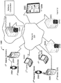
- FIG. 12 illustrates a diagram of a network environment in which the techniques described herein may be applied.
- FIG. 13 illustrates a block diagram of an example computing system that may be used in an embodiment of one or more of the servers, the wearable electronic device, and the client devices discussed herein.
- FIG. 1 illustrates an embodiment of a diagram of a caseback having multiple, arc-shaped, ferrous, metal contacts, such as physical pins, contact pads, terminals, prongs, etc., that serve a dual purpose.
- the arc-shaped, ferrous, metal contacts i) establish a physical electrical input connection between a battery for the wearable electronic device and charging prongs of an external electrical charger, rather than a wireless electrical coupling, and ii) establish a magnetic coupling between the wearable electronic device and multiple magnets in the external electrical charger to hold the metal contacts of the wearable electronic device and the charging prongs of the external electrical charger in place during a charging of the battery for the wearable electronic device.
- the arc-shaped, ferrous, metal contacts may take the form, for example, of either i) two or ii) four concentric metal contact rings on the surface of the caseback.
- the arc-shaped, ferrous, metal contacts in combination with the magnets located spatially positioned around a center of the external electrical charger are used to magnetically hold the charger prongs of the external electrical charger to the caseback side of the smart watch.
- the caseback also has a male extension.
- the male extension extends from a surface of the caseback.
- a heart rate sensor may be located in the male extension of the wearable electronic device.
- the heart rate sensor is electrically connected to the battery.
- the wearable electronic device may be a smart watch, Activity tracker, etc.
- FIG. 2 illustrates a diagram of an embodiment of a caseback having a male extension extending from a surface of the caseback to couple into a female receptor of the external electrical charger.
- the male extension may not be a uniform curved surface for the entire length of the back of the wearable electronic device but rather an extension in the Z axis from the rest of the surface of the wearable electronic device. Instead, the male extension can be more of a bump off the surface.
- FIG. 3 illustrates a diagram of an embodiment of the male extension extending from the surface of the caseback that houses the heart rate sensor and is surrounded by the concentric metal contact rings.
- the male extension creates a mechanical ‘male-female’ seating with a matching shaped female receptor in the external electrical charger, where the male extension takes the form and shape of a curved dome rising in the Z direction from the surface plane of the caseback.
- This curved dome spans merely a portion of the surface plane of the caseback and does not extend for an entire length of the caseback.
- the curved dome may span the surface plane of the caseback.
- the base material of the caseback can be made of i) ceramic, ii) plastic, or iii) a combination of both.
- the “bump” or extension for the optical heart rate tracking creates a mechanical ‘male-female’ seating or “self seat”.
- the bump can be made of i) glass, ii) ceramic, iii) plastic, or iv) a combination of all three.
- the bump or extension takes the form and shape of an oval dome rising from the surface plane of the case back.
- the charger generally has a matching shaped female receptor in the external electrical charger for the different shapes the male extension may be implemented in.
- the male extension extending from the surface of the caseback can be a mechanical oval dome that houses one or more sensors including the heart rate sensor.
- the concentric metal contact rings and mechanical oval dome mate to the external electrical charger to combine to provide a user experience with the external electrical charger to achieve a 360 degree rotation between the concentric metal contact rings and the charger prongs via magnetic attraction, mechanical coupling, and automatic centering.
- FIG. 4 illustrates an embodiment of the male extension of the caseback, where the male extension has a semi-circular or at least oval shape.
- a corresponding matching oval depression in the female receptor of the external electrical charger combines with the male extension to allow a free rotation when mating the wearable electronic device and the external electrical charger before, during, and after a charging of the battery process.
- An alignment of i) the multiple, arc-shaped, ferrous, metal contacts and the male extension of the wearable electronic device with ii) the magnets in the external electrical charger and the female receptacle of the external electrical charger establishes a flexible coupling between these devices that allows a 360 degree rotation axis for a physical and electrical coupling between the wearable electronic device and the external electrical charger.
- the 360 degree rotation axis for the physical and electrical coupling is not limited to one or two positional relationships on how these devices couple together before and during the charging process for the battery.
- the 360 degree mating between charger and the wearable electronic device is enabled before, during, and after charging to allow coupling from virtually all of the different possible mating positions. Because of the 360 degree mechanical alignment between the male extension and the female receptor, then no fixed alignment between the devices is needed.
- the external electrical charger using contacts has three or more magnets to create a pull force to magnetically connect to the caseback portion of the wearable electronic device.
- the caseback of the wearable electronic device uses ferrous (magnetic) metals to attract the charger and “self connect” to the electrical charger in a proper alignment to conduct the subsequent electrical charging of the battery of the wearable electronic device.
- the multiple, arc-shaped, ferrous, metal contacts use the ferrous metals to attract and create a pull force of at least 150 grams to the magnets of the external electrical charger to establish a proper alignment to conduct a subsequent electrical charging of the battery of the wearable electronic device.
- the pull force may also be, for example, between 200 grams to 140 grams.
- the pull force/magnetic force can be a measure of an amount attractive force from a magnet to a ferrous material.
- the multiple, arc-shaped, ferrous, metal contacts in the wearable electronic device and the three or more magnets spatially located inside the charger use the pull force of at least 150 grams to charge and recharge the wearable electronic device with a 360 degree rotation and improved user experience, via magnetic coupling to self-connect the metal contacts with the prongs of the charger in a proper alignment.
- the electrical charger can merely require that the metal contacts comes in close proximity of the prongs of the charger but in most cases a direct contact between these will be made.
- the wearable electronic device by utilizing multiple, e.g. two or four, concentric contact rings on the wearable electronic device, in combination with magnetic forces hold the charger centered to the watch's back side.
- the mechanical extension/bump of the heart rate dome and the concentric ring design of the ferrous metal contacts provide a user experience of an electrical charging with a 360 degree rotation/magnetic attraction and centering, and with a speed and an efficiency of a contact charging such as a full charge in less than an hour.
- the charger itself essentially retains the familiar prongs, (e.g. pins, pads, etc.) but the prongs are spring loaded to adjust to terrain of the caseback's surface.
- the mechanical and magnetic coupling allow an ease of use where the user does not need to search for contact pins and/or specific alignment to mate these devices. Instead the spatial placing of the magnets and the mechanical oval shapes of the dome and female receptacle essentially automatically align regardless of angle orientation between watch and charger.
- the arc-shaped, ferrous, metal contacts can take the form of, e.g., two or more concentric metal contact rings on a surface of the wearable electronic device, which in combination with the magnets located in the external electrical charger are configured to magnetically to couple the charging pins in the external electrical charger.
- the male extension extending from the surface of the caseback coupling with the female receptor of the external electrical charger is configured to mechanically couple the external electrical charger to the wearable electronic device.
- the mechanical coupling and the magnetic coupling creates an alignment in the three dimensions, the Z axis, the X axis, and the Y axis to allow a sufficient level of electrical current charge exchanged from the external electrical charger to the battery of the wearable electronic device to charge the battery from 0 to 100% to occur in less than sixty minutes while maintaining an external surface temperature around the concentric metal contact rings of no greater than 95 degrees F.
- the contact rings' temperature will naturally heat up during the charge but will not heat to greater than 95 degrees F. so if the user puts the wearable electronic device on during or immediately after a charge, they will not be burned by the metal contact rings.
- a full charge from 0 to 100% may occur in about an hour or less, (e.g. 30-31 minutes) while maintaining an external surface temperature around the metal contacts of no greater than 100 degrees F.
- FIG. 5 and FIG. 6 illustrate an embodiment of diagrams of the external electrical charger having an indented female receptacle and pogo pins for charging.
- the example, pogo pins make a physical connection extend from the charger to the metal contacts on surface of the wearable device.
- the external electrical charger has an indented female receptacle in the electrical charger in which the male extension may easily mechanically seat into.
- FIG. 10 illustrates a diagram of an embodiment of example magnets located spatially positioned around a center of the external electrical charger.
- Multiple magnetics such as three or more magnetics, located under the surface of the charger, assist in making the magnetic coupling between electrical contacts on the surface of the smart watch and the electrical charger.
- Each magnet is spatially positioned around the charger to make an tight coupling from that arc/quadrant/region of the connection between the wearable device and the electrical charger.
- a magnetic “click” feature can give confidence of a proper alignment between the charger and the wearable device.
- the wearable device on the display screen may have an icon or other indication in a user interface indicating a battery charge is occurring when the display is activated, as well as, a LED may illuminate on the charger to confirm charging is occurring.
- FIGS. 11A and 11B illustrate embodiments of diagrams of different casebacks having different layouts of multiple, arc-shaped, ferrous, arc-shaped, ferrous, metal contacts. Note, the male extensions are not shown in these diagrams.
- an overload circuit in the wearable electronic device and ii) one or more water seals in the caseback cooperate to maintain a water proofness to at least three atmospheres, such as 5 ATMs, by merely needing a water seal for each of the arc-shaped, ferrous, metal contacts penetrating the surface of the wearable electronic device.
- the wearable electronic device maintains water proofness by merely needing a water seal for each mechanical contact penetrating to the surface of the wearable in combination with the overload circuit to electrically open up the electrical circuit between the battery and the exposed surface contacts when the circuit senses either no contact from a contact proximity sensor for the wearable device or when an electrical short condition is detected.
- the wearable electronic device also uses a variety of water resistant rings to seal the watch to ensure the specific water proofness rating desired is achieved.
- the waterproof material prevents water molecules from penetrating through its layered composite fabric when compressed up to 1 atm, 4 atms, 5 atms or more or waterproof and/or water resistant to level 1 of the IPX liquid intrusion table, level 2, level 3, level 4, level 5, level 6, level 7, level 8 or up to level 9K.
- FIGS. 7A and 7B illustrate diagrams of an embodiment of a male extension extending from a surface of the caseback and its set of concentric rings.
- the metal contacts may be made out a corrosion resistant metal that retain magnetic ferrous properties such as 304 or 400 stainless steel, etc.
- the metal contacts are metal inserts on the surface of and/or through the plastic or ceramic material making up the bulk of the caseback. In an embodiment, the metal contacts may be slightly recessed from the surface. In an embodiment, the metal contacts of the wearable device are slight raised off the surface of the wearable device.
- the plastic or ceramic caseback is integrated into the rest of the plastic case of the wearable device, where positionally the charging metal rings are the light colored circles and the male extension is the black assembly with the LEDs and clear light sensors in the center.
- FIG. 8 illustrates a diagram of an embodiment of an example wearable electronic device having a display, one or more processors, one or more memories, one or more batteries, and a caseback.
- the wearable electronic device may include various components including a housing with a display screen.
- One or more processors are located in the housing.
- the processor is configured to process commands to present an onscreen display on the display screen to enable the wearer of the electronic device to select a number of different operations.
- One or more non-transitory computer readable storage mediums in the housing are accessible to the processor for storing instructions executable by the processor to generate the number of different operations on the onscreen display.
- a communication circuit is located in the housing.
- the communication circuit is configured to transmit wirelessly, such as Bluetooth, Zigbee, Cellular, Wi-Fi, etc. to another computing device cooperating with the wearable electronic device.
- One or more rechargeable batteries are used for the wearable electronic device.
- the watch may display electronic hands and/or may have mechanical hands.
- the wearable electronic device may be a smart watch or smart activity tracker.
- the caseback may be used with any wrist worn electronic device requiring an electrical or data based connection with a need for freedom to rotate when electrically coupling.
- an Analog quartz watch with small screen may also use the caseback with the concentric ring to charge its battery.
- the watch may use NFC communications (active and passive), use GPS, and possibly have cellular connectivity (e.g. 3G/4G/5G/).
- FIG. 9 illustrates a diagram of an embodiment of an example overload circuit located inside the wearable electronic device that is configured to prevent a flow of electrical current between the arc-shaped, ferrous, metal contacts going to a rest of a battery circuit in the wearable electronic device when the electrical current equals or exceeds a set point for a maximum input current.
- a similar overload circuit may be employed in the external electrical charger.
- the caseback has multiple electrical contacts in the form of multiple concentric rings made out of a ferrous material, each ring corresponding to a different electrical polarity for the DC charge of the battery.
- the overload circuit includes a circuit breaking type of device, such as a circuit breaker, an overload diode, an integrated circuit, etc., that electrically opens an electrical circuit from the arc-shaped, ferrous, metal contacts going to the rest of the battery circuit in the wearable electronic device and prevents the electrical current condition that would equal or exceed the maximum input current from harming the battery or other portions of the wearable electronic device.
- the circuit breaking type of device will be re-enabled and when the electrical current condition equals or exceeds the maximum input current remains, then the circuit breaking type of device will again be electrically opened.
- the circuit design may include an integrated circuit, such as a T.I. BQ24308 device, which includes the over current protection and the continuous auto-retry features.
- the smart wearable device uses a specific overload circuit so that accidental pin touches to an opposite DC electrical polarity a circuit breaking type of device such as a circuit breaker, an overload diode, integrated circuit, etc. electrically opens the electrical circuit from the metal contact going to the rest of the battery circuit in the smart wearable device and does not harm the battery or other portions of the smart wearable device.
- a circuit breaking type of device such as a circuit breaker, an overload diode, integrated circuit, etc. electrically opens the electrical circuit from the metal contact going to the rest of the battery circuit in the smart wearable device and does not harm the battery or other portions of the smart wearable device.
- the short circuit conditions are expected to occur often with the prongs of the charger and/or the surface contacts of the wearable device.
- the pogo pins of the charger and or concentric rings of the wearable device which carry USB +5V and Ground are fully exposed with no mechanical protection features.
- the cable of the external electrical charger includes magnets which may pull unintended magnetic materials into the pogo pins.
- the over current protection (OCP) feature allows the charging cable's pogo pins to contact any conductive surface, for any period of time, without damaging the cable or the USB input source (i.e. USB port, or USB AC adapter). Also, once the short circuit condition is removed, the charging cable continues to operate normally after a small delay.
- the OCP circuit prevents the flow of current when it exceeds the maximum input current specification of the wearable device. In this case, the maximum current that may be drawn by the watch is 500 milliamps.
- the output voltage is disabled, and the electrical current falls to 0 mA. Periodically, the output will be reenabled. If the short circuit remains, the output will again be disabled. This auto-retry mechanism occurs continuously until the short circuit is removed, and the output current is no greater than 500 mA.
- the wearable electronic device includes one or more communication and processing systems, which can be coupled externally to one or more networks.
- FIGS. 12-13 illustrate additional example environments to implement the concepts.
- the housing also has a computer readable storage medium in the housing accessible to the processor for storing instructions executable by the processor to generate the number of different operations on the onscreen display.
- FIG. 13 illustrates a block diagram of an example computing system that may be used in an embodiment of one or more of the servers, a wearable electronic device, and client devices discussed herein.
- the computing system environment 1300 is only one example of a suitable computing environment, such as a client device, server, wearable electronic device, etc., and is not intended to suggest any limitation as to the scope of use or functionality of the design of the computing system 810 . Neither should the computing environment 1300 be interpreted as having any dependency or requirement relating to any one or combination of components illustrated in the exemplary operating environment 1300 .
- the wearable electronic device can connect through a wireless network to an app store having thousands of applications and watchfaces that can be downloaded.
- the applications include notifications for emails, calls, text messages & social media activity; stock prices; activity tracking (movement, sleep, estimates of calories burned); remote controls for smartphones, cameras & home appliances; turn-by-turn directions (using the GPS receiver in a smartphone or tablet); display of RSS or JSON feeds; and also include hundreds of custom watch faces.
- the wearable electronic device can originally be shipped with applications pre-installed. These applications can use data received from a connected phone for distance, speed and range information. The applications can also directly connect to a backend server on the cloud. More applications are downloadable via a mobile phone or tablet.
- the wearable electronic device can integrates with any phone or tablet application that sends out native iOS or Android notifications.
- the wearable electronic device also has a computer readable storage medium, e.g., solid-state memory 840 , in the housing accessible to the processor 820 and stores instructions executable by the processor to generate the number of different operations on the onscreen display 891 .
- a computer readable storage medium e.g., solid-state memory 840
- the wearable electronic device is a wristwatch that has a watch housing in which the onscreen display bears a time indication, either digital or analog.
- the wristwatch may be a smart watch.
- the wristwatch has one or more manipulatable physical buttons that are arranged on the housing of the watch.
- the wristwatch may have a touch screen, scrolling device, additional buttons or a combination of some or all of these.
- a flexible wristband is engagable with the housing of the watch to hold the housing of the watch onto a wearer.
- the electronic wearable device has a bezel coupled to the display screen as well has a lithium based battery.
- the lithium-based battery is located in the housing.
- the lithium-based battery has at least 130 milliampere-hour (mAh) in electrical storage capacity, and can power the electronic components in a wearable electronic device.
- the lithium-based battery can also power the display screen, the communication circuit, and the processor.
- the display screen can be selected from the group of any of an ePaper display, a monochrome LCD display, and a color LED backlit display, and OLED display, that all consume lower battery power than some other color LCD screens.
- the battery contains enough capacity of at least 130 mAh to allow the display screen to stay on constantly and last up to multiple days on a single charge of the battery.
- the wearable electronic device is a smart watch which features a LCD display screen, a programmable CPU, memory, storage, Bluetooth, a vibrating motor, a heart rate sensor, GPS, and an accelerometer. These features extend the smart watch's use beyond just displaying the time on the display screen and into many roles including interacting with smartphone notifications, activity tracking, gaming, map display, golf tracking, and more.
- the smart watch is compatible with Android and iOS devices. When connected to one of these devices via Bluetooth, the smart watch can (but may not need to) pair with that device and vibrate and display text messages, fitness information, emails, incoming calls, and notifications from social media accounts.
- the smart watch can also act as a remote control for the telephone function in the paired device, or for other paired devices containing a camera such as the GoPro.
- components of the computing system 810 may include, but are not limited to, a processing unit 820 having one or more processing cores, a system memory 830 , and a system bus 821 that couples various system components including the system memory to the processing unit 820 .
- the system bus 821 may be any of several types of bus structures including a memory bus or memory controller, a peripheral bus, and a local bus using any of a variety of bus architectures.
- bus architectures include Industry Standard Architecture (ISA) bus, Micro Channel Architecture (MCA) bus, Enhanced ISA (EISA) bus, Video Electronics Standards Association (VESA) locale bus, and Peripheral Component Interconnect (PCI) bus.
- Computing system 810 typically includes a variety of computing machine-readable media.
- Computing machine-readable media can be any available media that can be accessed by computing system 810 and includes both volatile and nonvolatile media, removable and non-removable media.
- computing machine-readable mediums uses include storage of information, such as computer readable instructions, data structures, other executable software or other data.
- Computer storage mediums include, but are not limited to, RAM, ROM, EEPROM, flash memory or other memory technology, CD-ROM, digital versatile disks (DVD) or other optical disk storage, magnetic cassettes, magnetic tape, magnetic disk storage or other magnetic storage devices, or any other tangible medium which can be used to store the desired information and which can be accessed by computing device 1300 .
- Transitory media such as wireless channels are not included in the machine-readable media.
- Communication media typically embodies computer readable instructions, data structures, other executable software, or other transport mechanism and includes any information delivery media.
- some clients on network 220 of FIG. 12 may not have any optical or magnetic storage.
- the system memory 830 includes computer storage media in the form of volatile and/or nonvolatile memory such as read only memory (ROM) 831 and random access memory (RAM) 832 .
- ROM read only memory
- RAM random access memory
- BIOS basic input/output system 833
- RAM 832 typically contains data and/or software that are immediately accessible to and/or presently being operated on by processing unit 820 .
- FIG. 13 illustrates that RAM can include a portion of the operating system 834 , other executable software 836 , and program data 837 .
- the computing system 810 may also include other removable/non-removable volatile/nonvolatile computer storage media.
- FIG. 13 illustrates a solid-state memory 841 .
- Other removable/non-removable, volatile/nonvolatile computer storage media that can be used in the exemplary operating environment include, but are not limited to, USB drives and devices, flash memory cards, solid state RAM, solid state ROM, and the like.
- the solid-state memory 841 is typically connected to the system bus 821 through a non-removable memory interface such as interface 840
- USB drive 851 is typically connected to the system bus 821 by a removable memory interface, such as interface 850 .
- the wearable electronic device can have RAM which can include some space for the OS, 24 some space for the applications, and some space for the services.
- the computer readable storage medium 841 stores Operating System software for smart watches to cooperate with both Android OS and iOS.
- the drives and their associated computer storage media discussed above and illustrated in FIG. 13 provide storage of computer readable instructions, data structures, other executable software and other data for the computing system 810 .
- the solid state memory 841 is illustrated for storing operating system 844 , other executable software 846 , and program data 847 .
- operating system 844 , other executable software 846 , and program data 847 are given different numbers here to illustrate that, at a minimum, they are different copies.
- a user may enter commands and information into the computing system 810 through input devices such as a keyboard, touchscreen, or even push button input component 862 , a microphone 863 , a pointing device and/or scrolling input component 861 , such as a mouse, trackball or touch pad.
- the microphone 863 may cooperate with speech recognition software.
- These and other input devices are often connected to the processing unit 820 through a user input interface 860 that is coupled to the system bus, but may be connected by other interface and bus structures, such as a parallel port, game port or a universal serial bus (USB).
- a display monitor 891 or other type of display screen device is also connected to the system bus 821 via an interface, such as a display and video interface 890 .
- computing devices may also include other peripheral output devices such as speakers 897 and other output device, which may be connected through an output peripheral interface 890 .
- the computing system 810 may operate in a networked environment using logical connections to one or more remote computers/client devices, such as a remote computing device 880 .
- the remote computing device 880 may be a wearable electronic device, a personal computer, a hand-held device, a server, a router, a network PC, a peer device or other common network node, and typically includes many or all of the elements described above relative to the computing system 810 .
- the logical connections depicted in FIG. 13 include a local area network (LAN) 871 and a wide area network (WAN) 873 , but may also include other networks.
- LAN local area network
- WAN wide area network
- a browser application may be resident on the computing device and stored in the memory.
- the computing system 810 When used in a LAN networking environment, the computing system 810 is connected to the LAN 871 through a network interface or adapter 870 , which can be a Bluetooth or Wi-Fi adapter.
- the computing system 810 When used in a WAN networking environment, the computing system 810 typically includes a modem 872 , e.g., a wireless network, or other means for establishing communications over the WAN 873 , such as the Internet.
- the wireless modem 872 which may be internal or external, may be connected to the system bus 821 via the user-input interface 860 , or other appropriate mechanism.
- FIG. 13 illustrates remote application programs 885 as residing on remote computing device 880 . It will be appreciated that the network connections shown are exemplary and other means of establishing a communications link between the computing devices may be used.
- the computing system may include a processor, a memory, a built in battery to power the computing device, an AC power input to charge the battery, a display screen, a built-in Wi-Fi circuitry to wirelessly communicate with a remote computing device connected to network.
- the present design can be carried out on a computing system such as that described with respect to FIG. 13 .
- the present design can be carried out on a server, a computing device devoted to message handling, or on a distributed system in which different portions of the present design are carried out on different parts of the distributed computing system.
- the wireless communication module 872 may employ a Wireless Application Protocol to establish a wireless communication channel.
- the wireless communication module 872 may implement a wireless networking standard such as Institute of Electrical and Electronics Engineers (IEEE) 802.11 standard, IEEE std. 802.11-1999, published by IEEE in 1999.
- IEEE Institute of Electrical and Electronics Engineers
- Examples of mobile computing devices may be a wearable electronic device, a laptop computer, a cell phone, a personal digital assistant, or other similar device with on board processing power and wireless communications ability that is powered by a Direct Current (DC) power source that supplies DC voltage to the mobile device and that is solely within the mobile computing device and needs to be recharged on a periodic basis, such as a fuel cell or a battery.
- DC Direct Current
- FIG. 12 illustrates a diagram of a network environment in which the techniques described herein may be applied.
- the network environment 1200 has a communications network 220 that connects server computing systems 204 A through 204 C, and at least one or more client computing systems 202 A to 202 F.
- the network 220 may be, for example, the Internet.
- the network 220 might be or include one or more of: an optical network, a cellular network, the Internet, a Local Area Network (LAN), Wide Area Network (WAN), satellite link, fiber network, cable network, or a combination of these and/or others.
- LAN Local Area Network
- WAN Wide Area Network
- client computing system and server computing system is for clarity in specifying who generally initiates a communication (the client computing system) and who responds (the server computing system). No hierarchy is implied unless explicitly stated. Both functions may be in a single communicating device, in which case the client-server and server-client relationship may be viewed as peer-to-peer. Thus, if two systems such as the client computing system 202 A and the server computing system 204 A can both initiate and respond to communications, their communication may be viewed as peer-to-peer.
- server computing systems 204 A and 204 -B may be viewed as peer-to-peer if each such communicating device is capable of initiation and response to communication.
- server computing systems 204 A- 204 C also have circuitry and software to communication with each other across the network 220 .
- One or more of the server computing systems 204 A to 204 C may be associated with a database such as, for example, the databases 206 A to 206 C.
- Each server may have one or more instances of a virtual server running on that physical server and multiple virtual instances may be implemented by the design.
- a firewall may be established between a client computing system 202 C and the network 220 to protect data integrity on the client computing system 202 C.
- Each server computing system 204 A- 204 C may have one or more firewalls.
- a cloud provider service can install and operate application software in the cloud and users can access the software service from the client devices.
- Cloud users who have a site in the cloud may not solely manage the cloud infrastructure and platform where the application runs.
- the servers and databases may be shared hardware where the user is given a certain amount of dedicate use of these resources.
- the user's cloud-based site is given a virtual amount of dedicated space and bandwidth in the cloud.
- Cloud applications can be different from other applications in their scalability which can be achieved by cloning tasks onto multiple virtual machines at run-time to meet changing work demand. Load balancers distribute the work over the set of virtual machines. This process is transparent to the cloud user, who sees only a single access point.
- the cloud-based remote access is coded to utilize a protocol, such as Hypertext Transfer Protocol (HTTP), to engage in a request and response cycle with both a mobile device application resident on a client device as well as a web-browser application resident on the client device.
- HTTP Hypertext Transfer Protocol
- the cloud-based remote access for a wearable electronic device can be accessed by a mobile device, a desktop, a tablet device, and other similar devices, anytime, anywhere.
- the cloud-based remote access to a wearable electronic device hosted on a cloud-based provider site is coded to engage in 1) the request and response cycle from all web browser based applications, 2) SMS/twitter based request and response message exchanges, 3) the request and response cycle from a dedicated on-line server, 4) the request and response cycle directly between a native mobile application resident on a client device and the cloud-based remote access to a wearable electronic device, and 5) combinations of these.
- the server computing system 204 A may include a server engine, a web page management component, a content management component, and a database management component.
- the server engine performs basic processing and operating system level tasks.
- the web page management component handles creation and display or routing of web pages or screens associated with receiving and providing digital content and digital advertisements. Users may access the server-computing device by means of a URL associated therewith.
- the content management component handles most of the functions in the embodiments described herein.
- the database management component includes storage and retrieval tasks with respect to the database, queries to the database, and storage of data.
- An embodiment of a server computing system to display information, such as a web page, etc. is discussed.
- An application including any program modules when executed on the server computing system 204 A, causes the server computing system 204 A to display windows and user interface screens on a portion of a media space, such as a web page.
- a user via a browser from the client computing system 202 A may interact with the web page, and then supply input to the query/fields and/or service presented by a user interface of the application.
- the web page may be served by a web server computing system 204 A on any Hypertext Markup Language (HTML) or Wireless Access Protocol (WAP) enabled client computing system 202 A or any equivalent thereof.
- HTML Hypertext Markup Language
- WAP Wireless Access Protocol
- the client mobile computing system 202 A may be a wearable electronic device, smart phone, a touch pad, a laptop, a netbook, etc.
- the client computing system 202 A may host a browser to interact with the server computing system 204 A.
- Each application has a code scripted to perform the functions that the software component is coded to carry out such as presenting fields and icons to take details of desired information. Algorithms, routines, and engines within the server computing system 204 A take the information from the presenting fields and icons and put that information into an appropriate storage medium such as a database.
- a comparison wizard is scripted to refer to a database and make use of such data.
- the applications may be hosted on the server computing system 204 A and served to the browser of the client computing system 202 A or directly to an app running on the client computing system 202 A. The applications then serve pages that allow entry of details and further pages that allow entry of more details.
- Any application and other scripted code components may be stored on a non-transitory computing machine-readable medium which, when executed on the machine causes the machine to perform those functions.
- the applications including program modules may be implemented as logical sequences of software code, hardware logic circuits, and any combination of the two, and portions of the application scripted in software code are stored in a non-transitory computing device readable medium in an executable format.
- the hardware logic consists of electronic circuits that follow the rules of Boolean Logic, software that contain patterns of instructions, or any combination of both.
- the device may include a barometer inside the housing of the device that also makes use of the microphone sealing component with one or more channels with the water resistant material for reasons of mechanical robustness as well as the pressure equalization benefit.
- the device may act as a barometer with the microphone seal with one or more channels to allow the sensed pressure internally in the device, the device uses this internal pressure to detect current depth of the device by the pressure.
- the invention is to be understood as not limited by the specific embodiments described herein, but only by scope of the appended claims.
Abstract
Description
Claims (20)
Priority Applications (4)
| Application Number | Priority Date | Filing Date | Title |
|---|---|---|---|
| US16/053,545 US10742048B2 (en) | 2018-08-02 | 2018-08-02 | Wearable electronic device with a caseback having multiple, arc-shaped, ferrous, metal contacts |
| CN201980064446.1A CN112913086B (en) | 2018-08-02 | 2019-05-03 | Wearable electronic device with bottom cover having multiple arcuate ferrous metal contacts |
| PCT/US2019/030529 WO2020027892A1 (en) | 2018-08-02 | 2019-05-03 | A wearable electronic device with a caseback having multiple, arc-shaped, ferrous, metal contacts |
| DE112019003890.7T DE112019003890T5 (en) | 2018-08-02 | 2019-05-03 | A portable electronic device that has a bottom case with multiple arcuate ferrous metal contacts |
Applications Claiming Priority (1)
| Application Number | Priority Date | Filing Date | Title |
|---|---|---|---|
| US16/053,545 US10742048B2 (en) | 2018-08-02 | 2018-08-02 | Wearable electronic device with a caseback having multiple, arc-shaped, ferrous, metal contacts |
Publications (2)
| Publication Number | Publication Date |
|---|---|
| US20200044466A1 US20200044466A1 (en) | 2020-02-06 |
| US10742048B2 true US10742048B2 (en) | 2020-08-11 |
Family
ID=69229335
Family Applications (1)
| Application Number | Title | Priority Date | Filing Date |
|---|---|---|---|
| US16/053,545 Active US10742048B2 (en) | 2018-08-02 | 2018-08-02 | Wearable electronic device with a caseback having multiple, arc-shaped, ferrous, metal contacts |
Country Status (4)
| Country | Link |
|---|---|
| US (1) | US10742048B2 (en) |
| CN (1) | CN112913086B (en) |
| DE (1) | DE112019003890T5 (en) |
| WO (1) | WO2020027892A1 (en) |
Cited By (2)
| Publication number | Priority date | Publication date | Assignee | Title |
|---|---|---|---|---|
| US11114871B2 (en) * | 2017-02-14 | 2021-09-07 | Jrd Communication Inc. | Smart wearable device and charger thereof |
| USD942379S1 (en) | 2019-08-08 | 2022-02-01 | Chargetab Inc. | Charger |
Families Citing this family (5)
| Publication number | Priority date | Publication date | Assignee | Title |
|---|---|---|---|---|
| DE112021003384T5 (en) * | 2020-06-22 | 2023-04-13 | Owlet Baby Care Inc. | INFANT MONITOR |
| FI130207B (en) * | 2021-05-10 | 2023-04-20 | Suunto Oy | A wearable device and a docking station |
| CN113820943A (en) * | 2021-08-09 | 2021-12-21 | 深圳市纳晶云科技有限公司 | Increase intelligent wrist-watch of comfort level of wearing |
| WO2023040777A1 (en) * | 2021-09-16 | 2023-03-23 | Oppo广东移动通信有限公司 | Strap mechanism, wearable apparatus, and charging assembly |
| WO2023244226A1 (en) * | 2022-06-15 | 2023-12-21 | Google Llc | Omni-directional charging interface for wearable computing device |
Citations (7)
| Publication number | Priority date | Publication date | Assignee | Title |
|---|---|---|---|---|
| US20130325394A1 (en) | 2010-09-30 | 2013-12-05 | Fitbit, Inc. | Methods and Systems for Processing Social Interactive Data and Sharing of Tracked Activity Associated with Locations |
| US20140142403A1 (en) | 2012-06-22 | 2014-05-22 | Fitbit, Inc. | Biometric monitoring device with heart rate measurement activated by a single user-gesture |
| US20150305974A1 (en) * | 2014-04-24 | 2015-10-29 | Sympara Medical, Inc. | Methods and devices for treating hypertension |
| US20160180999A1 (en) | 2014-12-23 | 2016-06-23 | Qualcomm Incorporated | Electromagnetic mating interface |
| US20160246453A1 (en) | 2015-02-24 | 2016-08-25 | Pebble Technology Corp. | Smartwatch or other wearable device configured to intuitively interact with a user |
| US9557716B1 (en) | 2015-09-20 | 2017-01-31 | Qualcomm Incorporated | Multipurpose magnetic crown on wearable device and adapter for power supply and audio, video and data access |
| US20170346320A1 (en) | 2016-05-31 | 2017-11-30 | Samsung Electronics Co., Ltd. | Apparatus for charging wearable electronic device |
Family Cites Families (4)
| Publication number | Priority date | Publication date | Assignee | Title |
|---|---|---|---|---|
| KR101204510B1 (en) * | 2012-07-09 | 2012-11-26 | (주)에스피에스 | Charging device for mobile phone |
| CN205104960U (en) * | 2014-09-30 | 2016-03-23 | 苹果公司 | A supplementary electronic equipment for wearable electronic equipment |
| CN205453877U (en) * | 2016-01-18 | 2016-08-10 | 普联技术有限公司 | Camera base |
| CN108206571A (en) * | 2018-02-14 | 2018-06-26 | 出门问问信息科技有限公司 | Electronic equipment and cradle |
-
2018
- 2018-08-02 US US16/053,545 patent/US10742048B2/en active Active
-
2019
- 2019-05-03 DE DE112019003890.7T patent/DE112019003890T5/en active Pending
- 2019-05-03 WO PCT/US2019/030529 patent/WO2020027892A1/en active Application Filing
- 2019-05-03 CN CN201980064446.1A patent/CN112913086B/en active Active
Patent Citations (7)
| Publication number | Priority date | Publication date | Assignee | Title |
|---|---|---|---|---|
| US20130325394A1 (en) | 2010-09-30 | 2013-12-05 | Fitbit, Inc. | Methods and Systems for Processing Social Interactive Data and Sharing of Tracked Activity Associated with Locations |
| US20140142403A1 (en) | 2012-06-22 | 2014-05-22 | Fitbit, Inc. | Biometric monitoring device with heart rate measurement activated by a single user-gesture |
| US20150305974A1 (en) * | 2014-04-24 | 2015-10-29 | Sympara Medical, Inc. | Methods and devices for treating hypertension |
| US20160180999A1 (en) | 2014-12-23 | 2016-06-23 | Qualcomm Incorporated | Electromagnetic mating interface |
| US20160246453A1 (en) | 2015-02-24 | 2016-08-25 | Pebble Technology Corp. | Smartwatch or other wearable device configured to intuitively interact with a user |
| US9557716B1 (en) | 2015-09-20 | 2017-01-31 | Qualcomm Incorporated | Multipurpose magnetic crown on wearable device and adapter for power supply and audio, video and data access |
| US20170346320A1 (en) | 2016-05-31 | 2017-11-30 | Samsung Electronics Co., Ltd. | Apparatus for charging wearable electronic device |
Non-Patent Citations (1)
| Title |
|---|
| Macy's, Q Gen 2 Marshal Stainless Steel Bracelet Touchscreen Smart Watch 45 mm FTW2109, Prior to Aug. 2, 2018, 5 pages, http://www.macys.com/shop/product/fossil-q-gen-2-marshal-stainless-steel-bracelet-touchscreen-smart-watch-45mm-ftw2109?ID=2921866, USA. |
Cited By (3)
| Publication number | Priority date | Publication date | Assignee | Title |
|---|---|---|---|---|
| US11114871B2 (en) * | 2017-02-14 | 2021-09-07 | Jrd Communication Inc. | Smart wearable device and charger thereof |
| USD942379S1 (en) | 2019-08-08 | 2022-02-01 | Chargetab Inc. | Charger |
| USD967765S1 (en) | 2019-08-08 | 2022-10-25 | Chargetab Inc. | Charger |
Also Published As
| Publication number | Publication date |
|---|---|
| CN112913086A (en) | 2021-06-04 |
| CN112913086B (en) | 2023-04-28 |
| DE112019003890T5 (en) | 2021-05-20 |
| US20200044466A1 (en) | 2020-02-06 |
| WO2020027892A1 (en) | 2020-02-06 |
Similar Documents
| Publication | Publication Date | Title |
|---|---|---|
| US10742048B2 (en) | Wearable electronic device with a caseback having multiple, arc-shaped, ferrous, metal contacts | |
| US9408009B1 (en) | Combined microphone seal and air pressure relief valve that maintains a water tight seal | |
| US20170206899A1 (en) | Better communication channel for requests and responses having an intelligent agent | |
| AU2021201059B2 (en) | Coordination of message alert presentations across devices based on device modes | |
| US11671835B2 (en) | Standalone wearable device configuration and interface | |
| US10674451B2 (en) | Power sensitive wireless communication radio management | |
| EP3363319B1 (en) | Band mounting structure and wearable electronic device including the same | |
| EP3794414B1 (en) | Smart watch with flexible display panel | |
| US9395696B2 (en) | Multi-purpose interface for a portable electronic device | |
| TW201830820A (en) | Circuits and methods for wearable device charging and wired control | |
| US20140285416A1 (en) | Short Range Wireless Powered Ring for User Interaction and Sensing | |
| CN106257428A (en) | For providing equipment and the method for the notice about wireless charging state | |
| WO2022109837A1 (en) | Electronic device, charging base and charging method | |
| US11337326B2 (en) | Electronic device with a switch to prevent over-discharging of device battery | |
| WO2015183558A1 (en) | Coordination of message alert presentations across devices based on device modes | |
| KR20170058636A (en) | Electronic device with bi-directional connector | |
| US20210026308A1 (en) | Subtractive manufacturing of an oversized mim blank | |
| EP2770399B1 (en) | Multi-purpose interface for a portable electronic device | |
| US10534414B2 (en) | Disaggregated mobile client |
Legal Events
| Date | Code | Title | Description |
|---|---|---|---|
| FEPP | Fee payment procedure |
Free format text: ENTITY STATUS SET TO UNDISCOUNTED (ORIGINAL EVENT CODE: BIG.); ENTITY STATUS OF PATENT OWNER: LARGE ENTITY |
|
| AS | Assignment |
Owner name: FOSSIL GROUP, INC., TEXAS Free format text: ASSIGNMENT OF ASSIGNORS INTEREST;ASSIGNORS:PIERCEY, BRAD WILLIAM;GERAGHTY, RYAN GRIFFIN;DALEY, SEAN E.;AND OTHERS;SIGNING DATES FROM 20180803 TO 20180821;REEL/FRAME:046668/0981 |
|
| AS | Assignment |
Owner name: JPMORGAN CHASE BANK, N.A., TEXAS Free format text: TERM LOAN SECURITY AGREEMENT;ASSIGNOR:FOSSIL GROUP, INC. (FORMERLY FOSSIL, INC.);REEL/FRAME:050592/0105 Effective date: 20190926 |
|
| AS | Assignment |
Owner name: JPMORGAN CHASE BANK, N.A., TEXAS Free format text: ABL SECURITY AGREEMENT;ASSIGNOR:FOSSIL GROUP, INC. (FORMERLY FOSSIL, INC.);REEL/FRAME:050592/0220 Effective date: 20190926 |
|
| STPP | Information on status: patent application and granting procedure in general |
Free format text: NON FINAL ACTION MAILED |
|
| STPP | Information on status: patent application and granting procedure in general |
Free format text: NOTICE OF ALLOWANCE MAILED -- APPLICATION RECEIVED IN OFFICE OF PUBLICATIONS |
|
| STPP | Information on status: patent application and granting procedure in general |
Free format text: PUBLICATIONS -- ISSUE FEE PAYMENT VERIFIED |
|
| STCF | Information on status: patent grant |
Free format text: PATENTED CASE |
|
| AS | Assignment |
Owner name: FOSSIL GROUP, INC., TEXAS Free format text: RELEASE BY SECURED PARTY;ASSIGNOR:JPMORGAN CHASE BANK, N.A.;REEL/FRAME:058080/0174 Effective date: 20211108 |
|
| FEPP | Fee payment procedure |
Free format text: MAINTENANCE FEE REMINDER MAILED (ORIGINAL EVENT CODE: REM.); ENTITY STATUS OF PATENT OWNER: LARGE ENTITY |