US10720718B2 - Branch connector and communication network - Google Patents
Branch connector and communication network Download PDFInfo
- Publication number
- US10720718B2 US10720718B2 US16/168,254 US201816168254A US10720718B2 US 10720718 B2 US10720718 B2 US 10720718B2 US 201816168254 A US201816168254 A US 201816168254A US 10720718 B2 US10720718 B2 US 10720718B2
- Authority
- US
- United States
- Prior art keywords
- housing
- cables
- pressure contact
- wiring route
- branch connector
- Prior art date
- Legal status (The legal status is an assumption and is not a legal conclusion. Google has not performed a legal analysis and makes no representation as to the accuracy of the status listed.)
- Active
Links
- 238000004891 communication Methods 0.000 title claims description 31
- 229910000859 α-Fe Inorganic materials 0.000 claims description 6
- 238000012986 modification Methods 0.000 description 21
- 230000004048 modification Effects 0.000 description 21
- 210000000078 claw Anatomy 0.000 description 9
- 238000003780 insertion Methods 0.000 description 8
- 230000037431 insertion Effects 0.000 description 8
- 238000000034 method Methods 0.000 description 4
- 239000000470 constituent Substances 0.000 description 3
- 238000013459 approach Methods 0.000 description 2
- 238000005192 partition Methods 0.000 description 2
- QNRATNLHPGXHMA-XZHTYLCXSA-N (r)-(6-ethoxyquinolin-4-yl)-[(2s,4s,5r)-5-ethyl-1-azabicyclo[2.2.2]octan-2-yl]methanol;hydrochloride Chemical compound Cl.C([C@H]([C@H](C1)CC)C2)CN1[C@@H]2[C@H](O)C1=CC=NC2=CC=C(OCC)C=C21 QNRATNLHPGXHMA-XZHTYLCXSA-N 0.000 description 1
- 230000008878 coupling Effects 0.000 description 1
- 238000010168 coupling process Methods 0.000 description 1
- 238000005859 coupling reaction Methods 0.000 description 1
- 238000010586 diagram Methods 0.000 description 1
- 238000012423 maintenance Methods 0.000 description 1
Images


Classifications
-
- H—ELECTRICITY
- H01—ELECTRIC ELEMENTS
- H01R—ELECTRICALLY-CONDUCTIVE CONNECTIONS; STRUCTURAL ASSOCIATIONS OF A PLURALITY OF MUTUALLY-INSULATED ELECTRICAL CONNECTING ELEMENTS; COUPLING DEVICES; CURRENT COLLECTORS
- H01R4/00—Electrically-conductive connections between two or more conductive members in direct contact, i.e. touching one another; Means for effecting or maintaining such contact; Electrically-conductive connections having two or more spaced connecting locations for conductors and using contact members penetrating insulation
- H01R4/24—Connections using contact members penetrating or cutting insulation or cable strands
- H01R4/2416—Connections using contact members penetrating or cutting insulation or cable strands the contact members having insulation-cutting edges, e.g. of tuning fork type
- H01R4/242—Connections using contact members penetrating or cutting insulation or cable strands the contact members having insulation-cutting edges, e.g. of tuning fork type the contact members being plates having a single slot
- H01R4/2425—Flat plates, e.g. multi-layered flat plates
- H01R4/2429—Flat plates, e.g. multi-layered flat plates mounted in an insulating base
-
- H—ELECTRICITY
- H01—ELECTRIC ELEMENTS
- H01R—ELECTRICALLY-CONDUCTIVE CONNECTIONS; STRUCTURAL ASSOCIATIONS OF A PLURALITY OF MUTUALLY-INSULATED ELECTRICAL CONNECTING ELEMENTS; COUPLING DEVICES; CURRENT COLLECTORS
- H01R13/00—Details of coupling devices of the kinds covered by groups H01R12/70 or H01R24/00 - H01R33/00
- H01R13/648—Protective earth or shield arrangements on coupling devices, e.g. anti-static shielding
- H01R13/658—High frequency shielding arrangements, e.g. against EMI [Electro-Magnetic Interference] or EMP [Electro-Magnetic Pulse]
- H01R13/6591—Specific features or arrangements of connection of shield to conductive members
-
- H—ELECTRICITY
- H01—ELECTRIC ELEMENTS
- H01R—ELECTRICALLY-CONDUCTIVE CONNECTIONS; STRUCTURAL ASSOCIATIONS OF A PLURALITY OF MUTUALLY-INSULATED ELECTRICAL CONNECTING ELEMENTS; COUPLING DEVICES; CURRENT COLLECTORS
- H01R4/00—Electrically-conductive connections between two or more conductive members in direct contact, i.e. touching one another; Means for effecting or maintaining such contact; Electrically-conductive connections having two or more spaced connecting locations for conductors and using contact members penetrating insulation
- H01R4/70—Insulation of connections
-
- H—ELECTRICITY
- H01—ELECTRIC ELEMENTS
- H01R—ELECTRICALLY-CONDUCTIVE CONNECTIONS; STRUCTURAL ASSOCIATIONS OF A PLURALITY OF MUTUALLY-INSULATED ELECTRICAL CONNECTING ELEMENTS; COUPLING DEVICES; CURRENT COLLECTORS
- H01R13/00—Details of coupling devices of the kinds covered by groups H01R12/70 or H01R24/00 - H01R33/00
- H01R13/646—Details of coupling devices of the kinds covered by groups H01R12/70 or H01R24/00 - H01R33/00 specially adapted for high-frequency, e.g. structures providing an impedance match or phase match
- H01R13/6461—Means for preventing cross-talk
- H01R13/6463—Means for preventing cross-talk using twisted pairs of wires
Definitions
- the present application relates to a branch connector to be used for branching a twisted pair cable, and a communication network using the branch connector.
- a conventional branch connector 100 includes a housing 102 having a pair of right and left terminal accommodating chambers 101 , and a pair of pressure contact terminals 110 arranged in the respective terminal accommodating chambers 101 .
- the pair of terminal accommodating chambers 101 is partitioned by a partition wall 103 .
- the partition wall 103 is provided with an upper split rib 104 protruded upwardly, and a lower split rib 105 projected downwardly.
- a beam portion 106 is provided at an intermediate position in the vertical direction of each of the terminal accommodating chambers 101 . The beam portion 106 is not arranged at the entry position of upper pressure contact blades 111 from the lower side.
- Each of the pressure contact terminals 110 includes the upper pressure contact blades 111 arranged at upper positions, and lower pressure contact blades 112 arranged at lower positions.
- the upper pressure contact blades 111 and the lower pressure contact blades 112 are coupled with each other.
- the two second cables W 2 partially unwound from the twist of the twisted pair cable are split by the lower split rib 105 and inserted into the pair of terminal accommodating chambers 101 from below the housing 102 .
- the respective pressure contact terminals 110 are inserted into the respective terminal accommodating chambers 101 from below the housing 102 .
- the second cables W 2 are prevented from moving upward by the beam portions 106 . Therefore, the upper pressure contact blades 111 of the pressure contact terminals 110 pass while cutting the insulating sheath of the second cables W 2 . Then, further insertion of the pressure contact terminals 110 from below the housing 102 is continued, so that the respective second cables W 2 are connected with corresponding lower pressure contact blades 112 by pressure contact.
- the two first cables W 1 partially unwound from the twist of the twisted pair cable are split by the upper split rib 104 and inserted into the pair of terminal accommodating chambers 101 from above the housing 102 .
- the respective first cables W 1 are inserted into the respective terminal accommodating chambers 101 of the housing 102 , the respective first cables W 1 are connected with corresponding upper pressure contact blades 111 by pressure contact.
- the two first cables W 1 constituting a twisted pair cable and corresponding two second cables W 2 constituting a twisted pair cable are electrically connected with each other via the pair of pressure contact terminals 110 .
- the conventional branch connector 100 has a problem that communication quality deteriorates, since the twisted shape of the two first cables W 1 constituting a twisted pair cable and the twisted shape of the two second cables W 2 constituting a twisted pair cable are both unwound in a section.
- the present application has been made with the aim of solving the above mentioned problems, and it is an object of the present application to provide a branch connector capable of branching a twisted pair cable while maintaining communication quality, and a communication network using the branch connector.
- a branch connector includes: a first housing having a wiring route portion in which two first cables constituting a twisted pair cable are wired in a twisted shape to be spaced apart from each other; and a second housing to which a pair of pressure contact terminals connected respectively with two second cables constituting a twisted pair cable are fixed, the pair of pressure contact terminals being connected respectively with the two first cables by pressure contact in a state where the second housing is assembled with the first housing.
- branch connector With the branch connector according to the aspect of the present application, it is possible to branch a twisted pair cable while maintaining communication quality, since wiring is achieved with the twisted shape being maintained though the distance between the two first cables is increased.
- FIG. 1 is an exploded perspective view of a branch connector according to a first embodiment.
- FIG. 2 is a general perspective view of the branch connector according to the first embodiment.
- FIG. 3A is a sectional view taken along line A 1 -A 1 of FIG. 2
- FIG. 3B is a sectional view taken along line A 2 -A 2 of FIG. 2
- FIG. 3C is a sectional view taken along line B-B of FIG. 2 .
- FIG. 4 is a perspective view of an inner face side of a first housing of the branch connector according to the first embodiment.
- FIG. 5A is a perspective view of an inner face side of a uniting housing portion of a second housing of the branch connector according to the first embodiment
- FIG. 5B is a perspective view of an outer face side of the uniting housing portion of the second housing of the branch connector according to the first embodiment.
- FIG. 6 is a plan view of a state where two first cables are wired in the first housing of the branch connector according to the first embodiment.
- FIG. 7 is a perspective view illustrating a state before the uniting housing portion is united with the first housing in the branch connector according to the first embodiment.
- FIG. 8 is a perspective view illustrating a state before a terminal fixing housing portion is fitted to the uniting housing portion in the branch connector according to the first embodiment.
- FIG. 9 is a sectional view illustrating a state before the terminal fixing housing portion is fitted to the uniting housing portion in the branch connector according to the first embodiment.
- FIG. 10 is a block diagram of a communication network using the branch connector according to the first embodiment and a branch connector according to a second embodiment.
- FIG. 11 is a general perspective view of the branch connector according to the second embodiment.
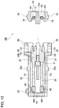
- FIG. 12 is a sectional view illustrating a state before a first housing is fitted to a second housing in the branch connector according to the second embodiment along line E-E of FIG. 11 .
- FIG. 13 is a sectional view illustrating a state where the first housing is fitted to the second housing in the branch connector according to the second embodiment along line E-E of FIG. 11 .
- FIG. 14 is a perspective view of a branch connector according to a first modification of the first embodiment.
- FIG. 15 is a schematic perspective view of a branch connector according to a second modification of the first embodiment.
- FIG. 16 is a schematic perspective view of a branch connector according to a third modification of the first embodiment.
- FIG. 17 is a perspective view of a conventional branch connector.
- FIG. 18 is a sectional view of the conventional branch connector.
- FIGS. 1 to 10 illustrate a first embodiment.
- a communication network 1 as illustrated in FIG. 10 is mounted on a vehicle.
- the communication network 1 includes: a trunk line w 1 ; a plurality of branch lines w 2 branched at a plurality of points of the trunk line w 1 ; a plurality of electronic control units (ECUs) 2 connected with the respective branch lines w 2 ; and two terminators 3 connected with both ends of the trunk line w 1 .
- Each of the ECUs 2 is equipped with a CAN interface (not illustrated).
- Each of the ECUs 2 transmits and receives signals by controller area network (CAN) communication.
- CAN controller area network
- trunk line w 1 For the trunk line w 1 , two first cables W 1 constituting a twisted pair cable are used. The two first cables W 1 are wired in a twisted shape substantially in close contact. For each of the branch lines w 2 , two second cables W 2 which also constitute a twisted pair cable are used. The two second cables W 2 are wired in a twisted shape substantially in close contact. In addition, branching from the twisted pair cable of the trunk line w 1 is achieved by a branch connector 5 A according to the first embodiment.
- the branch connector 5 A includes: a first housing 10 in which two first cables W 1 constituting a twisted pair cable on the side of the trunk line w 1 pass and are wired; and a second housing 20 to which a pair of pressure contact terminals 50 connected with two second cables W 2 constituting a twisted pair cable on the side of each of the branch lines w 2 is fixed.
- the first housing 10 has a substantially rectangular plate shape.
- the first housing 10 is provided with a wiring route portion 11 .
- the wiring route portion 11 is provided with twist grooves 12 , and three ribs 13 a , 13 b erected at intervals in the wiring direction of the two first cables W 1 .
- the twist grooves 12 are formed as grooves having shapes following the twisted shape of the two first cables W 1 spaced apart from each other.
- the three ribs 13 a , 13 b are arranged at an interval substantially equal to the interval of the twist pitch P between the two first cables W 1 .
- the central rib 13 a is substantially rhombic when viewed from above.
- the central positions where both side faces of the central rib 13 a are most separated from each other become the pressure contact positions of the pair of pressure contact terminals 50 .
- the ribs 13 b on the respective both end sides are substantially isosceles triangular when viewed from above.
- the three ribs 13 a , 13 b of the wiring route portion 11 respectively wedge into a space between the two first cables W 1 , so that the distance between the two first cables W 1 is increased while maintaining the twisted shape, and the two first cables W 1 are wired in the twist grooves 12 in a twisted shape.
- the two first cables W 1 wired in the twist grooves 12 are drawn out of the first housing 10 from both ends of the twist grooves 12 .
- the twist pitch of the two first cables W 1 in the wiring route portion 11 is substantially equal to the twist pitch P of the two first cables W 1 other than in the wiring route portion 11 .
- the wiring route portion 11 is provided with a pair of pressure contact blade guide grooves 14 continuous from the top face of the central rib 13 a to the bottom face of each of the twist grooves 12 .
- Each of the pressure contact blade guide grooves 14 is formed to have a thickness dimension substantially equal to the thickness of a pressure contact blade 52 , or a slightly larger width dimension.
- a pair of first locking claws 15 is projected from both side faces of the first housing 10 .
- the second housing 20 includes a uniting housing 21 to be assembled with the first housing 10 , and a terminal fixing housing 31 , which is separate from the uniting housing 21 and to which the pair of pressure contact terminals 50 is fixed.
- the uniting housing 21 has an upper face wall 22 formed to have a dimension slightly larger than the first housing 10 , and four side walls 23 a , 23 b vertically provided from the entire circumference edge of the upper face wall 22 .
- a projecting wall 24 having a shape following the shapes of the twist grooves 12 (a shape following a twisted shape with an increased distance between the two first cables W 1 ) is provided on an inner face of the upper face wall 22 .
- the projecting wall 24 enters into the twist grooves 12 in a state of being assembled with the first housing 10 .
- a positioning recess 24 a is provided inside the upper face wall 22 by being surrounded by the projecting wall 24 .
- a pair of positioning holes 22 a is formed at both end portions of the upper face wall 22 .
- a pair of pressure contact blade approach holes 25 (see FIGS. 3A and 5A , and the like) is formed at the upper face wall 22 .
- the four side walls 23 a , 23 b of the uniting housing 21 are arranged at positions to cover the entire side face of the first housing 10 in a state of being assembled with the first housing 10 .
- a pair of cable insertion grooves 26 is formed respectively in the pair of first side walls 23 a orthogonal to the wiring direction of the first cables W 1 .
- a rib 27 is provided between the pair of cable insertion grooves 26 of each of the side wall 23 a . The rib 27 wedges into a space between the two first cables W 1 together with the ribs 13 b on both end sides of the first housing 10 in a state of being assembled with the first housing 10 .
- a pair of elastic locking frames 28 is provided at the pair of second side walls 23 b extending along the same direction as the wiring direction of the first cables W 1 .
- the pair of elastic locking frames 28 is locked to the pair of first locking claws 15 of the first housing 10 , so that the uniting housing 21 of the second housing 20 is assembled with the first housing 10 .
- the uniting housing 21 includes a connector fitting portion 29 on the upper face of the upper face wall 22 .
- the pair of pressure contact blade approach holes 25 is opened in a portion inside the connector fitting portion 29 of the upper face wall 22 .
- a pair of elastic locking frames 30 is provided on the side of the fitting entrance of the connector fitting portion 29 .
- the terminal fixing housing 31 is fitted to the connector fitting portion 29 .
- the terminal fixing housing 31 includes a connector housing 32 , and a closing cover 34 coupled with the connector housing 32 via a hinge 33 .
- a terminal accommodating chamber 35 is provided inside the connector housing 32 .
- a rear wall 32 a of the connector housing 32 is provided with a terminal insertion port 36 .
- a front wall 32 b of the connector housing 32 is provided with a pressure contact blade protrusion port 37 .
- the connector housing 32 is provided with a lance fitting port 38 to which a locking lance 41 is fitted.
- a pair of second locking claws 39 a is provided on the front portion side of the connector housing 32 .
- a pair of third locking claws 39 b is provided on the rear portion side of the connector housing 32 .
- a cable draw-out groove 34 a is formed at the closing cover 34 .
- a pair of elastic locking frames 40 is projected from the closing cover 34 .
- Each of the pressure contact terminals 50 includes a crimp portion 51 to be crimped and connected with the corresponding second cable W 2 , and a pressure contact blade 52 to be connected with the corresponding first cable W 1 by pressure contact.
- the crimp portion 51 of each of the pressure contact terminals 50 is crimped and connected with an end portion of the corresponding second cable W 2 unwound from the twisted shape.
- a cylindrical ferrite component 42 is mounted on the outer circumference of an end portion of each of the second cables W 2 unwound from the twisted shape.
- the pair of pressure contact terminals 50 is arranged in the terminal accommodating chamber 35 of the connector housing 32 in a state where the pressure contact terminals 50 are positioned by the locking lance 41 and the like.
- the pressure contact blades 52 of the respective pressure contact terminals 50 protrude from the pressure contact blade protrusion port 37 .
- the two second cables W 2 connected with the pair of pressure contact terminals 50 are drawn out of the connector housing 32 through the terminal insertion port 36 and the cable draw-out groove 34 a.
- the two first cables W 1 constituting the twisted pair cable are inserted into the twist grooves 12 of the first housing 10 . Insertion of the two first cables W 1 into the twist grooves 12 can be easily achieved by causing the ribs 13 a , 13 b to wedge into three places between the two first cables W 1 . As illustrated in FIG. 6 , the two first cables W 1 inserted into the twist grooves 12 are wired in a twisted shape with an increased distance between the two first cables.
- the uniting housing 21 of the second housing 20 is united with the first housing 10 . That is, the uniting housing 21 of the second housing 20 is placed over the first housing 10 , and the elastic locking frames 30 of the uniting housing 21 are locked to the first locking claws 15 of the first housing 10 . As a result, the projecting wall 24 of the uniting housing 21 enters into the twist grooves 12 of the first housing 10 , and the first cables W 1 are positioned in the twist grooves 12 .
- the tip side of the central rib 13 a enters into the positioning recess 24 a of the uniting housing 21 .
- the pair of ribs 13 b on both end sides enters into a pair of positioning recesses 24 a of the uniting housing 21 .
- the operation of connecting the pressure contact terminals 50 respectively with the two second cables W 2 constituting the twisted pair cable, and the operation of fixing the pressure contact terminals 50 to the terminal fixing housing 31 are performed before or after the operation of uniting the first housing 10 and the uniting housing 21 .
- the operation of connecting the pressure contact terminals 50 with the two second cables W 2 is to peel the sheath of the end portions of the two second cables W 2 .
- the ferrite component 42 is mounted on the far side from the end portion of each of the second cables W 2 .
- the crimp portion 51 of each of the pressure contact terminals 50 is crimped and connected with an end portion of the corresponding second cable W 2 .
- the operation of connecting the pressure contact terminals 50 with the two second cables W 2 is completed.
- the operation of fixing the pressure contact terminals 50 to the terminal fixing housing 31 is such that the closing cover 34 is set in an open position and the pair of pressure contact terminals 50 is inserted into the terminal accommodating chamber 35 of the connector housing 32 with the pressure contact blades 52 of the pressure contact terminals located at the tip.
- the locking lance 41 is fitted through the lance fitting port 38 .
- the pair of pressure contact terminals 50 is fixed to the terminal fixing housing 31 .
- the closing cover 34 is set in a close position, and the elastic locking frame 40 of the closing cover 34 is locked to the third locking claws 39 b of the terminal fixing housing 31 .
- the operation of fixing the pressure contact terminals 50 to the terminal fixing housing 31 is completed.
- the terminal fixing housing 31 is fitted to the connector fitting portion 29 of the uniting housing 21 . That is, the terminal fixing housing 31 is inserted into the connector fitting portion 29 of the uniting housing 21 , and the elastic locking frames 30 of the connector fitting portion 29 are locked to the second locking claws 39 a of the terminal fixing housing 31 .
- the pressure contact blades 52 of the pair of pressure contact terminals 50 enter into the twist grooves 12 while being guided by the pressure contact blade guide grooves 14 .
- the respective pressure contact blades 52 of the pair of pressure contact terminals 50 are connected with the respective first cables W 1 by pressure contact.
- the branch connector 5 A includes: the first housing 10 having the wiring route portion 11 in which the two first cables W 1 constituting a twisted pair cable is wired in a twisted shape with an increased distance between the two first cables W 1 ; and the second housing 20 to which the pair of pressure contact terminals 50 respectively connected with the two second cables W 2 constituting a twisted pair cable is fixed, in which the pair of pressure contact terminals 50 is respectively connected with the two first cables W 1 by pressure contact in a state where the second housing 20 is assembled with the first housing 10 .
- the wiring route portion 11 has the twist grooves 12 following the twisted shape of the two first cables W 1 spaced apart from each other. Accordingly, the twisted shape of the two first cables W 1 can be reliably maintained, and it is therefore possible to reliably maintain communication quality.
- the wiring route portion 11 has the ribs 13 a , 13 b that wedge into spaces between the two first cables W 1 . Accordingly, it is possible to easily increase the distance between the two first cables W 1 .
- the uniting housing 21 of the second housing 20 includes the projecting wall 24 that enters into the twist grooves 12 in a state where the second housing 20 is assembled with the first housing 10 . Accordingly, the first cables W 1 can be reliably positioned in the twist grooves 12 , and this contributes to maintenance of communication quality.
- the projecting wall 24 has a shape following the shape of the twist grooves 12 (a shape following the twisted shape with an increased distance between the two first cables W 1 ), and it is therefore possible to achieve reliable positioning over the whole area of the twist grooves 12 .
- the second housing 20 includes: the uniting housing 21 which is assembled with the first housing 10 and has the connector fitting portion 29 ; and the terminal fixing housing 31 to which the pair of pressure contact terminals 50 is fixed and which is fitted to the connector fitting portion 29 .
- the branch connector 5 A can perform the operation of branching a twisted pair cable by operation similar to male and female connectors connection.
- the degree of freedom in operation is improved, since the operation of assembling the first housing 10 and the uniting housing 21 with the trunk line w 1 (trunk line w 1 side operation), and the operation of fitting the terminal fixing housing 31 , which is connected with branch line w 2 , with the uniting housing 21 (operation of connecting the branch line w 2 with the trunk line w 1 ) can be performed at separate timing.
- the ribs 13 a , 13 b of the two first cables W 1 are interposed between the two first cables W 1 constituting a twisted pair cable at three places, and the pressure contact blades 52 are connected to the two first cables W 1 by pressure contact at the positions of the central rib 13 a . Accordingly, even if tensile force of the two first cables W 1 acts on the branch connector 5 A, the tensile force of the first cable W 1 does not directly act on the pressure contact connection place by the pressure contact blades 52 , and therefore the reliability of the pressure contact connection is high.
- the ferrite components 42 are mounted respectively on the outer circumference of the end portions of the pair of second cables W 2 to which the pair of pressure contact terminals 50 is fixed. Although the end portions of the pair of second cables W 2 are fixed to the pair of pressure contact terminals 50 in a state where the twisted shape is unwound, it is possible to prevent lowering of communication quality as much as possible, since electromagnetic noise from the respective second cables W 2 is reduced by the ferrite components 42 .
- the communication network 1 includes: the two first cables W 1 constituting a twisted pair cable; the two second cables W 2 constituting a twisted pair cable; and the branch connector 5 A, which connects the two first cables W 1 with the two second cables W 2 and has the above-mentioned structure. Accordingly, although the distance between the two first cables W 1 is increased in the branch connector 5 A, wiring is achieved with the twisted shape being maintained even in the branch connector 5 A. As described above, it is possible to obtain a communication network 1 in which a twisted pair cable is branched while maintaining communication quality.
- FIGS. 10 to 13 illustrate a second embodiment.
- a communication network 1 according to the second embodiment has a structure similar to that of the first embodiment (see FIG. 10 ).
- a branch connector (branch connection structure) 5 B according to the second embodiment is used for branching a twisted pair cable.
- the branch connector 5 B according to the second embodiment is different from the branch connector 5 A according to the first embodiment in that a second housing 20 is formed of a single housing.
- a uniting housing 21 to be assembled with a first housing 10 and a terminal fixing housing 31 to which a pair of pressure contact terminals 50 is fixed are formed integrally with each other. Since the second housing 20 is formed integrally in such a manner, the second locking claws 39 a and the elastic locking frames 30 configured to lock the uniting housing 21 and the terminal fixing housing 31 to each other in the first embodiment are not provided.
- Two first cables W 1 constituting a twisted pair cable are inserted into the twist grooves 12 of the first housing 10 as described in the first embodiment.
- the uniting housing 21 of the second housing 20 is united with the first housing 10 .
- the projecting wall 24 of the uniting housing 21 enters into the twist grooves 12 of the first housing 10 , and the first cables W 1 are positioned in the twist grooves 12 .
- the pressure contact blades 52 of the pair of pressure contact terminals 50 enter into the twist grooves 12 while being guided by the pressure contact blade guide grooves 14 .
- the respective pressure contact blades 52 of the pair of pressure contact terminals 50 are connected with the respective first cables W 1 by pressure contact.
- branch connector 5 B it is also possible to branch a twisted pair cable while maintaining communication quality for a reason similar to that of the first embodiment, since the two first cables W 1 are wired with the twisted shape being maintained though the distance between the two first cables W 1 is increased in the branch connector 5 B.
- the uniting housing 21 to be assembled with the first housing 10 and the terminal fixing housing 31 to which the pair of pressure contact terminals 50 is fixed are formed integrally with each other. Therefore, with the branch connector 5 B according to the second embodiment, it is unnecessary to perform the operation of fitting the uniting housing 21 and the terminal fixing housing 31 to each other, and therefore the operability in assembling of the branch connector 5 B is better than that of the first embodiment. Moreover, the branch connector 5 B according to the second embodiment is reduced in the number of components, and reduced in weight or the like compared to the first embodiment.
- the communication network 1 according to the second embodiment includes the branch connector 5 B having the above-mentioned structure configured to connect the two first cables W 1 and the two second cables W 2 with each other. Accordingly, with the second embodiment, it is also possible to obtain the communication network 1 in which a twisted pair cable is branched while maintaining communication quality for a reason similar to that of the first embodiment.
- FIG. 14 illustrates a first modification of the first embodiment.
- a branch connector 5 A according to the first modification is different from the first embodiment in the structure of a terminal fixing housing 31 A. That is, the terminal fixing housing 31 A of the first modification is configured to draw out the second cables W 2 in a direction orthogonal to the fitting direction of the connector fitting portion 29 . In the first modification, the second cables W 2 can be drawn out smoothly in a desired wiring direction when the wiring route of the second cables W 2 is parallel to the first cables W 1 .
- the other structure of the first modification is the same as that of the first embodiment.
- the same constituent parts as those of the first embodiment are denoted by the same reference numerals, and the description thereof is omitted.
- the first modification can also be applied to the branch connector 5 B according to the second embodiment.
- FIG. 15 illustrates a second modification of the first embodiment.
- a branch connector 5 A according to the second modification is different from the first embodiment in that fastening bands 43 are provided at the uniting housing 21 .
- the branch connector 5 A can be fixed to the cable (trunk line) W of a wire harness by the fastening bands 43 .
- the second modification can also be applied to fixing of the branch connector 5 A to members other than a cable (trunk line) W.
- the other structure of the second modification is the same as that of the first embodiment.
- the same constituent parts as those of the first embodiment are denoted by the same reference numerals, and the description thereof is omitted.
- the second modification can also be applied to the branch connector 5 B according to the second embodiment.
- FIG. 16 illustrates a third modification of the first embodiment.
- a branch connector 5 A according to the third modification is different from the first embodiment in that coupling portions 44 , 45 are provided at both end portions of the uniting housing 21 .
- a plurality of branch connectors 5 A can be coupled. This is convenient in the case of branching a plurality of sets of second cables W 2 at the same branch point of a trunk line w 1 .
- the plurality of branch connectors 5 A can be integrated, the plurality of branch connectors 5 A can be handled as a single component, and excellent component handleability can be obtained. For example, there is no need to perform operation of fixing each individual branch connector 5 A to a vehicle body.
- the second housing 20 has one pair of pressure contact terminals 50 , that is, one set of pressure contact terminals 50 in each of the above embodiments, the second housing 20 may have a plurality of sets of pressure contact terminals 50 .
- a plurality of sets of pressure contact terminals 50 may be connected with one set of (two constituting a twisted pair cable) second cables W 2 , or a plurality of sets of pressure contact terminals 50 may be connected respectively with a plurality of sets of second cables W 2 .
- the number of ribs may be one, two, four or more.
- the wiring route portion 11 is formed of the twist grooves 12 and the ribs 13 a , 13 b in each of the above embodiments, any structure may be employed as long as the two first cables W 1 can be wired in a twisted shape with an increased distance between the two first cables W 1 .
- the wiring route portion 11 may be configured with only the twist grooves 12 , or may be configured with only the rib 13 a.
- the wiring route portion 11 has the twist grooves 12 in each of the above embodiments, a pair of side walls following a twisted shape with an increased distance between the two first cables W 1 may be erected and formed at the first housing 10 .
- the pair of side walls may be intermittent side walls instead of continuous side walls.
- the projecting wall 24 provided at the uniting housing 21 of the second housing 20 has a shape following the shape of the twist grooves 12 (a shape following the twisted shape with an increased distance between the two first cables W 1 ) in each of the above embodiments, a plurality of projecting walls intermittently inserted into the twist grooves 12 may be employed.
Landscapes
- Connections By Means Of Piercing Elements, Nuts, Or Screws (AREA)
Abstract
Description
Claims (16)
Applications Claiming Priority (4)
| Application Number | Priority Date | Filing Date | Title |
|---|---|---|---|
| JP2017-206247 | 2017-10-25 | ||
| JP2017206247 | 2017-10-25 | ||
| JP2018-063784 | 2018-03-29 | ||
| JP2018063784A JP7044606B2 (en) | 2017-10-25 | 2018-03-29 | Branch connector and communication network |
Publications (2)
| Publication Number | Publication Date |
|---|---|
| US20190123459A1 US20190123459A1 (en) | 2019-04-25 |
| US10720718B2 true US10720718B2 (en) | 2020-07-21 |
Family
ID=65996318
Family Applications (1)
| Application Number | Title | Priority Date | Filing Date |
|---|---|---|---|
| US16/168,254 Active US10720718B2 (en) | 2017-10-25 | 2018-10-23 | Branch connector and communication network |
Country Status (2)
| Country | Link |
|---|---|
| US (1) | US10720718B2 (en) |
| DE (1) | DE102018218035B4 (en) |
Cited By (1)
| Publication number | Priority date | Publication date | Assignee | Title |
|---|---|---|---|---|
| US11482809B2 (en) * | 2018-06-05 | 2022-10-25 | Rosenburger Hochfrequenztechnik GmbH & Co. KG | Modular plug connector system |
Families Citing this family (2)
| Publication number | Priority date | Publication date | Assignee | Title |
|---|---|---|---|---|
| US10637176B1 (en) * | 2019-03-14 | 2020-04-28 | Aptiv Technologies Limited | Connector assembly with retainer |
| CN114759382A (en) * | 2021-01-08 | 2022-07-15 | 康普技术有限责任公司 | Communication cable connector |
Citations (23)
| Publication number | Priority date | Publication date | Assignee | Title |
|---|---|---|---|---|
| US4778405A (en) * | 1984-10-05 | 1988-10-18 | Amp Incorporated | T-tap electrical connector having opening for test probe |
| US5556297A (en) * | 1994-10-31 | 1996-09-17 | Sea Gull Lighting | Snap-on extension wire socket with electrical conductor insulation piercer |
| US5934930A (en) * | 1996-07-02 | 1999-08-10 | Pouyet S.A. | Interconnection of two electric cables |
| US5942964A (en) * | 1996-07-19 | 1999-08-24 | Takeuchi Industrial Co., Ltd. | Noise absorbing apparatus |
| US6285265B1 (en) * | 1998-09-10 | 2001-09-04 | Kitagawa Industries Co., Ltd. | Electric noise absorber housing with convex surface |
| US6512425B2 (en) * | 1998-09-10 | 2003-01-28 | Kitagawa Industries Co., Ltd. | Electric noise absorber |
| US20030184204A1 (en) * | 2002-04-02 | 2003-10-02 | Mccoy Phillip | Electrical connector |
| US6633000B2 (en) * | 2001-02-23 | 2003-10-14 | Hon Hai Precision Ind. Co., Ltd. | Noise filter with an improved insulating case |
| US6716055B1 (en) * | 2002-11-25 | 2004-04-06 | American Tack & Hardware Co., Inc. | Electrical connector for connecting a branched circuit to a main power source |
| US6769931B2 (en) * | 2002-03-20 | 2004-08-03 | Yazaki Corporation | Connector for connecting electric wire of added device with provided electric wire |
| US6827600B2 (en) * | 2002-03-20 | 2004-12-07 | Yazaki Corporation | Paired electrical cable connector |
| US7273389B2 (en) * | 2003-02-10 | 2007-09-25 | Tyco Electronics Amp Gmbh | Connecting arrangement and production method for a connecting arrangement |
| US7319376B2 (en) * | 2005-11-29 | 2008-01-15 | Tdk Corporation | Noise filter |
| US7341474B2 (en) * | 2006-05-08 | 2008-03-11 | Tektronix, Inc. | Lumped resistance electrical cable |
| US7550670B2 (en) * | 2006-07-07 | 2009-06-23 | Hon Hai Precision Ind. Co., Ltd | Cable assembly |
| US20100093206A1 (en) * | 2008-10-15 | 2010-04-15 | Checkson Die Casting And Product Factory Limited | Electrical connector for electrical communication between a power cable and an electrical device |
| US7859378B2 (en) * | 2006-09-14 | 2010-12-28 | Ambient Corporation | Housing for inductive coupler for power line communications |
| US8182281B2 (en) * | 2007-10-30 | 2012-05-22 | Commscope, Inc. Of North Carolina | Devices for connecting conductors of twisted pair cable to insulation displacement contacts |
| US8188395B2 (en) * | 2006-02-10 | 2012-05-29 | Marquardt Gmbh | Electric switch |
| US20160164574A1 (en) * | 2013-07-26 | 2016-06-09 | Koninklijke Philips N.V. | Contactless pick-up of a signal |
| JP2016115505A (en) | 2014-12-15 | 2016-06-23 | 株式会社オートネットワーク技術研究所 | Trunk line structure in vehicle on-board network, and connector for vehicle on-board network |
| US9379492B2 (en) * | 2012-08-07 | 2016-06-28 | Rosenberger Hochfrequenztechnik Gmbh & Co. Kg | Insertion type connector |
| JP2016152147A (en) | 2015-02-18 | 2016-08-22 | 株式会社オートネットワーク技術研究所 | Connector |
Family Cites Families (9)
| Publication number | Priority date | Publication date | Assignee | Title |
|---|---|---|---|---|
| US1315317A (en) | 1919-09-09 | Device toe joining electrical cokductors | ||
| JPH04342967A (en) | 1991-05-20 | 1992-11-30 | Fujikura Ltd | Bus branch connector and branch method |
| JPH0696810A (en) | 1992-09-11 | 1994-04-08 | Fujikura Ltd | Connector |
| DE4413977C2 (en) | 1994-04-21 | 1996-02-22 | Knorr Bremse Systeme | Cable junction of a data bus for connecting electronic control units in passenger cars and commercial vehicles |
| JP2002151169A (en) | 2000-11-09 | 2002-05-24 | Auto Network Gijutsu Kenkyusho:Kk | Connecting structure of branch connector |
| JP3924187B2 (en) | 2002-03-20 | 2007-06-06 | 矢崎総業株式会社 | connector |
| KR100803555B1 (en) | 2006-09-25 | 2008-02-15 | 현대자동차주식회사 | Joint connector for twist wire |
| JP5203436B2 (en) | 2010-09-21 | 2013-06-05 | 矢崎総業株式会社 | connector |
| JP6663895B2 (en) | 2017-10-05 | 2020-03-13 | 矢崎総業株式会社 | connector |
-
2018
- 2018-10-22 DE DE102018218035.0A patent/DE102018218035B4/en active Active
- 2018-10-23 US US16/168,254 patent/US10720718B2/en active Active
Patent Citations (26)
| Publication number | Priority date | Publication date | Assignee | Title |
|---|---|---|---|---|
| US4778405A (en) * | 1984-10-05 | 1988-10-18 | Amp Incorporated | T-tap electrical connector having opening for test probe |
| US5556297A (en) * | 1994-10-31 | 1996-09-17 | Sea Gull Lighting | Snap-on extension wire socket with electrical conductor insulation piercer |
| US5934930A (en) * | 1996-07-02 | 1999-08-10 | Pouyet S.A. | Interconnection of two electric cables |
| US5942964A (en) * | 1996-07-19 | 1999-08-24 | Takeuchi Industrial Co., Ltd. | Noise absorbing apparatus |
| US6285265B1 (en) * | 1998-09-10 | 2001-09-04 | Kitagawa Industries Co., Ltd. | Electric noise absorber housing with convex surface |
| US6512425B2 (en) * | 1998-09-10 | 2003-01-28 | Kitagawa Industries Co., Ltd. | Electric noise absorber |
| US6633000B2 (en) * | 2001-02-23 | 2003-10-14 | Hon Hai Precision Ind. Co., Ltd. | Noise filter with an improved insulating case |
| US6769931B2 (en) * | 2002-03-20 | 2004-08-03 | Yazaki Corporation | Connector for connecting electric wire of added device with provided electric wire |
| US6827600B2 (en) * | 2002-03-20 | 2004-12-07 | Yazaki Corporation | Paired electrical cable connector |
| US20030184204A1 (en) * | 2002-04-02 | 2003-10-02 | Mccoy Phillip | Electrical connector |
| US6716055B1 (en) * | 2002-11-25 | 2004-04-06 | American Tack & Hardware Co., Inc. | Electrical connector for connecting a branched circuit to a main power source |
| US7273389B2 (en) * | 2003-02-10 | 2007-09-25 | Tyco Electronics Amp Gmbh | Connecting arrangement and production method for a connecting arrangement |
| US7319376B2 (en) * | 2005-11-29 | 2008-01-15 | Tdk Corporation | Noise filter |
| US8188395B2 (en) * | 2006-02-10 | 2012-05-29 | Marquardt Gmbh | Electric switch |
| US7892021B2 (en) * | 2006-05-08 | 2011-02-22 | Tektronix, Inc. | Lumped resistance electrical cable |
| US7341474B2 (en) * | 2006-05-08 | 2008-03-11 | Tektronix, Inc. | Lumped resistance electrical cable |
| US7550670B2 (en) * | 2006-07-07 | 2009-06-23 | Hon Hai Precision Ind. Co., Ltd | Cable assembly |
| US7859378B2 (en) * | 2006-09-14 | 2010-12-28 | Ambient Corporation | Housing for inductive coupler for power line communications |
| US8182281B2 (en) * | 2007-10-30 | 2012-05-22 | Commscope, Inc. Of North Carolina | Devices for connecting conductors of twisted pair cable to insulation displacement contacts |
| US20100093206A1 (en) * | 2008-10-15 | 2010-04-15 | Checkson Die Casting And Product Factory Limited | Electrical connector for electrical communication between a power cable and an electrical device |
| US9379492B2 (en) * | 2012-08-07 | 2016-06-28 | Rosenberger Hochfrequenztechnik Gmbh & Co. Kg | Insertion type connector |
| US20160164574A1 (en) * | 2013-07-26 | 2016-06-09 | Koninklijke Philips N.V. | Contactless pick-up of a signal |
| JP2016115505A (en) | 2014-12-15 | 2016-06-23 | 株式会社オートネットワーク技術研究所 | Trunk line structure in vehicle on-board network, and connector for vehicle on-board network |
| US20170264064A1 (en) | 2014-12-15 | 2017-09-14 | Autonetworks Technologies, Ltd. | Trunk line structure in in-vehicle network and connector for in-vehicle network |
| JP2016152147A (en) | 2015-02-18 | 2016-08-22 | 株式会社オートネットワーク技術研究所 | Connector |
| US20180034168A1 (en) * | 2015-02-18 | 2018-02-01 | Autonetworks Technologies, Ltd. | Connector |
Cited By (1)
| Publication number | Priority date | Publication date | Assignee | Title |
|---|---|---|---|---|
| US11482809B2 (en) * | 2018-06-05 | 2022-10-25 | Rosenburger Hochfrequenztechnik GmbH & Co. KG | Modular plug connector system |
Also Published As
| Publication number | Publication date |
|---|---|
| DE102018218035B4 (en) | 2024-05-23 |
| DE102018218035A1 (en) | 2019-04-25 |
| US20190123459A1 (en) | 2019-04-25 |
Similar Documents
| Publication | Publication Date | Title |
|---|---|---|
| US10720718B2 (en) | Branch connector and communication network | |
| US9601742B2 (en) | Busbar module unit | |
| US7950968B2 (en) | Electrical connector having detachable cover | |
| US10971851B2 (en) | Miniaturized connector with a terminal holding member | |
| KR100367942B1 (en) | Splice receiving structure | |
| US7074093B2 (en) | Splice absorbing structure for motor vehicle | |
| US10367319B2 (en) | Trunk line structure in in-vehicle network and connector for in-vehicle network | |
| US6712623B2 (en) | Junction box | |
| US6846197B2 (en) | Modular plug | |
| US20210399499A1 (en) | Terminal module and connector | |
| US11217943B2 (en) | Shield terminal including structures having different dielectric constants | |
| US11031724B2 (en) | Stacked connector and wire harness | |
| US10079445B2 (en) | Electrical connector for a twisted pair cable | |
| JP2019079782A (en) | Branch connector and communication network | |
| US20150111444A1 (en) | Joint terminal | |
| JP4317079B2 (en) | Electric wire converging structure of joint box | |
| JP2576858Y2 (en) | connector | |
| KR102088326B1 (en) | Fakra terminal | |
| JP6927847B2 (en) | Branch connector and communication network | |
| KR102519137B1 (en) | Module connector assembly | |
| US20230231340A1 (en) | Wire cover and connector structure | |
| JP7036569B2 (en) | Branch connector and communication network | |
| US20220109267A1 (en) | Connector | |
| JP3275281B2 (en) | Joint connector | |
| JP6959102B2 (en) | Branch connector for termination and communication network |
Legal Events
| Date | Code | Title | Description |
|---|---|---|---|
| FEPP | Fee payment procedure |
Free format text: ENTITY STATUS SET TO UNDISCOUNTED (ORIGINAL EVENT CODE: BIG.); ENTITY STATUS OF PATENT OWNER: LARGE ENTITY |
|
| AS | Assignment |
Owner name: YAZAKI CORPORATION, JAPAN Free format text: ASSIGNMENT OF ASSIGNORS INTEREST;ASSIGNORS:KIMURA, SYUJI;ITOU, GAKU;AKASHI, MASANORI;REEL/FRAME:047309/0359 Effective date: 20180822 |
|
| STPP | Information on status: patent application and granting procedure in general |
Free format text: DOCKETED NEW CASE - READY FOR EXAMINATION |
|
| STPP | Information on status: patent application and granting procedure in general |
Free format text: NON FINAL ACTION MAILED |
|
| STPP | Information on status: patent application and granting procedure in general |
Free format text: RESPONSE TO NON-FINAL OFFICE ACTION ENTERED AND FORWARDED TO EXAMINER |
|
| STPP | Information on status: patent application and granting procedure in general |
Free format text: FINAL REJECTION MAILED |
|
| STPP | Information on status: patent application and granting procedure in general |
Free format text: NOTICE OF ALLOWANCE MAILED -- APPLICATION RECEIVED IN OFFICE OF PUBLICATIONS |
|
| STPP | Information on status: patent application and granting procedure in general |
Free format text: PUBLICATIONS -- ISSUE FEE PAYMENT VERIFIED |
|
| STCF | Information on status: patent grant |
Free format text: PATENTED CASE |
|
| AS | Assignment |
Owner name: YAZAKI CORPORATION, JAPAN Free format text: CHANGE OF ADDRESS;ASSIGNOR:YAZAKI CORPORATION;REEL/FRAME:063845/0802 Effective date: 20230331 |
|
| MAFP | Maintenance fee payment |
Free format text: PAYMENT OF MAINTENANCE FEE, 4TH YEAR, LARGE ENTITY (ORIGINAL EVENT CODE: M1551); ENTITY STATUS OF PATENT OWNER: LARGE ENTITY Year of fee payment: 4 |