US10701344B2 - Information processing device, information processing system, control method of an information processing device, and parameter setting method - Google Patents
Information processing device, information processing system, control method of an information processing device, and parameter setting method Download PDFInfo
- Publication number
- US10701344B2 US10701344B2 US15/780,148 US201615780148A US10701344B2 US 10701344 B2 US10701344 B2 US 10701344B2 US 201615780148 A US201615780148 A US 201615780148A US 10701344 B2 US10701344 B2 US 10701344B2
- Authority
- US
- United States
- Prior art keywords
- viewpoint
- image
- display
- rotation angle
- subject
- Prior art date
- Legal status (The legal status is an assumption and is not a legal conclusion. Google has not performed a legal analysis and makes no representation as to the accuracy of the status listed.)
- Active
Links
- 230000010365 information processing Effects 0.000 title claims abstract description 64
- 238000000034 method Methods 0.000 title claims description 53
- 238000003384 imaging method Methods 0.000 claims description 62
- 230000002194 synthesizing effect Effects 0.000 claims description 7
- 238000004891 communication Methods 0.000 abstract description 31
- 238000005516 engineering process Methods 0.000 abstract description 9
- 230000005540 biological transmission Effects 0.000 description 32
- 230000009466 transformation Effects 0.000 description 19
- 239000013598 vector Substances 0.000 description 14
- 230000006870 function Effects 0.000 description 13
- 238000006243 chemical reaction Methods 0.000 description 6
- 239000000284 extract Substances 0.000 description 6
- 238000010586 diagram Methods 0.000 description 4
- 238000005070 sampling Methods 0.000 description 3
- 238000013519 translation Methods 0.000 description 3
- 238000004590 computer program Methods 0.000 description 2
- 239000011521 glass Substances 0.000 description 2
- 238000004519 manufacturing process Methods 0.000 description 2
- 239000003550 marker Substances 0.000 description 2
- 239000011159 matrix material Substances 0.000 description 2
- 238000004364 calculation method Methods 0.000 description 1
- 239000002131 composite material Substances 0.000 description 1
- 230000001419 dependent effect Effects 0.000 description 1
- 230000000694 effects Effects 0.000 description 1
- 230000005484 gravity Effects 0.000 description 1
- 210000003128 head Anatomy 0.000 description 1
- 230000003993 interaction Effects 0.000 description 1
- 238000013507 mapping Methods 0.000 description 1
- 230000003287 optical effect Effects 0.000 description 1
- 230000001360 synchronised effect Effects 0.000 description 1
- 238000002366 time-of-flight method Methods 0.000 description 1
- 238000012546 transfer Methods 0.000 description 1
Images


Classifications
-
- H—ELECTRICITY
- H04—ELECTRIC COMMUNICATION TECHNIQUE
- H04N—PICTORIAL COMMUNICATION, e.g. TELEVISION
- H04N13/00—Stereoscopic video systems; Multi-view video systems; Details thereof
- H04N13/20—Image signal generators
- H04N13/275—Image signal generators from 3D object models, e.g. computer-generated stereoscopic image signals
-
- G—PHYSICS
- G06—COMPUTING; CALCULATING OR COUNTING
- G06T—IMAGE DATA PROCESSING OR GENERATION, IN GENERAL
- G06T17/00—Three dimensional [3D] modelling, e.g. data description of 3D objects
-
- G—PHYSICS
- G09—EDUCATION; CRYPTOGRAPHY; DISPLAY; ADVERTISING; SEALS
- G09G—ARRANGEMENTS OR CIRCUITS FOR CONTROL OF INDICATING DEVICES USING STATIC MEANS TO PRESENT VARIABLE INFORMATION
- G09G5/00—Control arrangements or circuits for visual indicators common to cathode-ray tube indicators and other visual indicators
- G09G5/36—Control arrangements or circuits for visual indicators common to cathode-ray tube indicators and other visual indicators characterised by the display of a graphic pattern, e.g. using an all-points-addressable [APA] memory
- G09G5/363—Graphics controllers
-
- H—ELECTRICITY
- H04—ELECTRIC COMMUNICATION TECHNIQUE
- H04N—PICTORIAL COMMUNICATION, e.g. TELEVISION
- H04N13/00—Stereoscopic video systems; Multi-view video systems; Details thereof
- H04N13/10—Processing, recording or transmission of stereoscopic or multi-view image signals
- H04N13/106—Processing image signals
- H04N13/111—Transformation of image signals corresponding to virtual viewpoints, e.g. spatial image interpolation
- H04N13/117—Transformation of image signals corresponding to virtual viewpoints, e.g. spatial image interpolation the virtual viewpoint locations being selected by the viewers or determined by viewer tracking
-
- H—ELECTRICITY
- H04—ELECTRIC COMMUNICATION TECHNIQUE
- H04N—PICTORIAL COMMUNICATION, e.g. TELEVISION
- H04N13/00—Stereoscopic video systems; Multi-view video systems; Details thereof
- H04N13/10—Processing, recording or transmission of stereoscopic or multi-view image signals
- H04N13/106—Processing image signals
- H04N13/156—Mixing image signals
-
- H—ELECTRICITY
- H04—ELECTRIC COMMUNICATION TECHNIQUE
- H04N—PICTORIAL COMMUNICATION, e.g. TELEVISION
- H04N13/00—Stereoscopic video systems; Multi-view video systems; Details thereof
- H04N13/20—Image signal generators
- H04N13/204—Image signal generators using stereoscopic image cameras
- H04N13/239—Image signal generators using stereoscopic image cameras using two 2D image sensors having a relative position equal to or related to the interocular distance
-
- H—ELECTRICITY
- H04—ELECTRIC COMMUNICATION TECHNIQUE
- H04N—PICTORIAL COMMUNICATION, e.g. TELEVISION
- H04N13/00—Stereoscopic video systems; Multi-view video systems; Details thereof
- H04N13/20—Image signal generators
- H04N13/204—Image signal generators using stereoscopic image cameras
- H04N13/25—Image signal generators using stereoscopic image cameras using two or more image sensors with different characteristics other than in their location or field of view, e.g. having different resolutions or colour pickup characteristics; using image signals from one sensor to control the characteristics of another sensor
-
- H—ELECTRICITY
- H04—ELECTRIC COMMUNICATION TECHNIQUE
- H04N—PICTORIAL COMMUNICATION, e.g. TELEVISION
- H04N13/00—Stereoscopic video systems; Multi-view video systems; Details thereof
- H04N13/30—Image reproducers
- H04N13/302—Image reproducers for viewing without the aid of special glasses, i.e. using autostereoscopic displays
- H04N13/305—Image reproducers for viewing without the aid of special glasses, i.e. using autostereoscopic displays using lenticular lenses, e.g. arrangements of cylindrical lenses
-
- H—ELECTRICITY
- H04—ELECTRIC COMMUNICATION TECHNIQUE
- H04N—PICTORIAL COMMUNICATION, e.g. TELEVISION
- H04N13/00—Stereoscopic video systems; Multi-view video systems; Details thereof
- H04N13/30—Image reproducers
- H04N13/349—Multi-view displays for displaying three or more geometrical viewpoints without viewer tracking
- H04N13/351—Multi-view displays for displaying three or more geometrical viewpoints without viewer tracking for displaying simultaneously
-
- H—ELECTRICITY
- H04—ELECTRIC COMMUNICATION TECHNIQUE
- H04N—PICTORIAL COMMUNICATION, e.g. TELEVISION
- H04N7/00—Television systems
- H04N7/14—Systems for two-way working
- H04N7/141—Systems for two-way working between two video terminals, e.g. videophone
- H04N7/142—Constructional details of the terminal equipment, e.g. arrangements of the camera and the display
-
- H—ELECTRICITY
- H04—ELECTRIC COMMUNICATION TECHNIQUE
- H04N—PICTORIAL COMMUNICATION, e.g. TELEVISION
- H04N7/00—Television systems
- H04N7/14—Systems for two-way working
- H04N7/141—Systems for two-way working between two video terminals, e.g. videophone
- H04N7/147—Communication arrangements, e.g. identifying the communication as a video-communication, intermediate storage of the signals
-
- H—ELECTRICITY
- H04—ELECTRIC COMMUNICATION TECHNIQUE
- H04N—PICTORIAL COMMUNICATION, e.g. TELEVISION
- H04N7/00—Television systems
- H04N7/14—Systems for two-way working
- H04N7/15—Conference systems
-
- G—PHYSICS
- G09—EDUCATION; CRYPTOGRAPHY; DISPLAY; ADVERTISING; SEALS
- G09G—ARRANGEMENTS OR CIRCUITS FOR CONTROL OF INDICATING DEVICES USING STATIC MEANS TO PRESENT VARIABLE INFORMATION
- G09G2320/00—Control of display operating conditions
- G09G2320/06—Adjustment of display parameters
- G09G2320/0693—Calibration of display systems
-
- G—PHYSICS
- G09—EDUCATION; CRYPTOGRAPHY; DISPLAY; ADVERTISING; SEALS
- G09G—ARRANGEMENTS OR CIRCUITS FOR CONTROL OF INDICATING DEVICES USING STATIC MEANS TO PRESENT VARIABLE INFORMATION
- G09G2360/00—Aspects of the architecture of display systems
- G09G2360/16—Calculation or use of calculated indices related to luminance levels in display data
-
- G—PHYSICS
- G09—EDUCATION; CRYPTOGRAPHY; DISPLAY; ADVERTISING; SEALS
- G09G—ARRANGEMENTS OR CIRCUITS FOR CONTROL OF INDICATING DEVICES USING STATIC MEANS TO PRESENT VARIABLE INFORMATION
- G09G3/00—Control arrangements or circuits, of interest only in connection with visual indicators other than cathode-ray tubes
- G09G3/001—Control arrangements or circuits, of interest only in connection with visual indicators other than cathode-ray tubes using specific devices not provided for in groups G09G3/02 - G09G3/36, e.g. using an intermediate record carrier such as a film slide; Projection systems; Display of non-alphanumerical information, solely or in combination with alphanumerical information, e.g. digital display on projected diapositive as background
- G09G3/003—Control arrangements or circuits, of interest only in connection with visual indicators other than cathode-ray tubes using specific devices not provided for in groups G09G3/02 - G09G3/36, e.g. using an intermediate record carrier such as a film slide; Projection systems; Display of non-alphanumerical information, solely or in combination with alphanumerical information, e.g. digital display on projected diapositive as background to produce spatial visual effects
-
- H—ELECTRICITY
- H04—ELECTRIC COMMUNICATION TECHNIQUE
- H04N—PICTORIAL COMMUNICATION, e.g. TELEVISION
- H04N13/00—Stereoscopic video systems; Multi-view video systems; Details thereof
- H04N2013/0074—Stereoscopic image analysis
- H04N2013/0081—Depth or disparity estimation from stereoscopic image signals
-
- H—ELECTRICITY
- H04—ELECTRIC COMMUNICATION TECHNIQUE
- H04N—PICTORIAL COMMUNICATION, e.g. TELEVISION
- H04N13/00—Stereoscopic video systems; Multi-view video systems; Details thereof
- H04N2013/0074—Stereoscopic image analysis
- H04N2013/0092—Image segmentation from stereoscopic image signals
Definitions
- the present invention relates to technology enabling presenting a display image based on a three-dimensional model.
- PTL 1 describes technology for generating a three-dimensional image of a space on the imaging side, and displaying on a display device a two-dimensional image corresponding to the viewpoint of the display side from the three-dimensional image.
- Technology for displaying an image photographed from multiple directions according to the direction in which the listener is looking in order to converse as though the eyes of the listener and the other party meet is also known from the literature (see, for example, PTL 2).
- a stereoscopic display viewable by multiple people from any direction is also known from the literature (see, for example, PTL 3).
- PTL 1 and PTL 2 are also silent regarding a specific method of adjustment to align the lines of sight of particular participants through the display screen in a video conference.
- video must be sent between remote conference rooms in the case of a video conference, and exchanging video recorded from multiple directions as described in PTL 2 requires a high data transfer speed, data volume, and other communication specifications for video conferencing, potentially increasing communication costs.
- the related technology requires adjusting the lines of sight to account for the participants' movements up and down as well as the participants' horizontal movements right and left.
- PTL 1 and PTL 2 also requires setting the camera according to the eye height of the subject, and adapting flexibly to various situations (such as differences in the height of the participants and whether the participants are standing or sitting) may be difficult. Furthermore, if multiple stereoscopic displays disclosed in PTL 3 are used in situations requiring two-way data communication such as video conferences, costs increase, assuring space sufficient for the stereoscopic displays may be difficult, and other structural problems may result.
- the present invention is directed to solving at least part of the foregoing problems, and can be embodied as described in the following embodiments and examples.
- An information processing device includes: a communicator; a multiple viewpoint image generator configured to, based on a three-dimensional model of a subject the communicator receives from an external device, generate a display image including a viewpoint image corresponding to the perspective of multiple viewpoints; and a display controller configured to display the display image on a multiple viewpoint display device that displays images corresponding to multiple viewpoints.
- this configuration can generate viewpoint images appropriate to multiple different viewpoints, and display a display image including the viewpoint images on a multiple viewpoint display device, and can thereby present a display image with realistic presence. Furthermore, by generating the viewpoint image based on a received three-dimensional model, the data communication volume can be reduced compared with a configuration that receives a viewpoint image for each of multiple different viewpoints.
- the foregoing information processing device may also have storage configured to store a parameter used to generate the viewpoint image according to the multiple viewpoints; the multiple viewpoint image generator generating the viewpoint image based on the parameter stored in the storage.
- This configuration can easily generate viewpoint images based on the parameters.
- This configuration can easily generate viewpoint images based on a three-dimensional model using rotation angle information.
- the information processing device described above may also have a parameter setting unit configured to set the rotation angle information based on an image of a subject the display controller displayed on the multiple viewpoint display device independently of the multiple viewpoints.
- This configuration can easily set the rotation angle information based on a subject image.
- the communicator receives a background image of the subject; the multiple viewpoint image generator generates a synthesized image of the background image and the viewpoint image; and the display controller displays the synthesized image as the display image on the multiple viewpoint display device.
- An information processing device includes a communicator; a multiple viewpoint image generator configured to, based on a three-dimensional model of a subject the communicator receives from an external device, generate a display image including a viewpoint image corresponding to the perspective of multiple viewpoints; a display controller configured to display the display image on a multiple viewpoint display device that displays images corresponding to multiple viewpoints; an imaging controller configured to acquire images of imaged subjects captured by multiple imaging devices; and a three-dimensional model generator configured to generate a three-dimensional model of the imaged subjects based on the images the multiple imaging devices captured; the communicator sending a three-dimensional model of the imaged subjects to an external device.
- This configuration can generate and send to an external device a three-dimensional model of an imaged subject based on a picture that was taken.
- the information processing device described above may also have an extractor configured to extract a background image that is a background of the imaged subject from the images captured by the multiple imaging devices; the communicator transmitting the background image to an external device.
- This configuration can extract and send to an external device a background image.
- the imaging controller can acquire depth information detected by a depth sensor disposed to each of the multiple imaging devices; and the three-dimensional model generator generates a three-dimensional model of the imaged subject based on images captured by each of the multiple imaging devices, and depth information detected by the multiple depth sensors.
- This configuration can easily generate a three-dimensional model of an imaged subject based on a captured image and depth information.
- the setting method includes (a) a step of displaying an image of a subject on a display device independently of the multiple viewpoints; and (b) a step of setting rotation angle information for rotating the three-dimensional model according to the viewpoint based on the image of a subject displayed by step (a).
- This configuration can set rotation angle information based on an image of a subject.
- step (a) includes a step of locating the subject on the second location side so that the direction in which a specific person viewing a first display device and displayed on a second display device different from the first display device, which is the display device disposed in a first location, is facing the subject located on the second location side where the second display device is located; and step (b) includes a step of setting an angle of rotation and direction of rotation of the image of the subject as the rotation angle information, when the subject on the second location side is positioned according to step (a), and the image of a subject is changed so that the image of a subject displayed on the first display device faces the direction of the specific person.
- This configuration can easily set rotation angle information by changing the image of the subject.
- Another aspect of the invention can be embodied as a device comprising one or more of the communicator, display controller, and multiple viewpoint image generator. More specifically, this device can be configured with or without a communicator. The device can also be configured with or without the display controller. The device can also be configured with or without the multiple viewpoint image generator. Such configurations can resolve at least one of the problems of reducing device size, reducing cost, improving energy efficiency, simplifying manufacture, and improving ease of use. In addition, one or all of the technical features of the information processing device or the parameter setting method described above can be applied to this device or method.
- the invention can be embodied in many ways, and in addition to an information processing device and a parameter setting method, can be embodied as an information processing system including the information processing device, a control method of an information processing device, a computer program for implementing the functions of the method, device, and system, and as a storage medium storing the computer program.
- FIG. 1 illustrates an image communication system according to an embodiment of the invention.
- FIG. 2 describes a multiple viewpoint display device.
- FIG. 3 is a function block diagram of an imaging device and a transmitter-side information processing device.
- FIG. 4 is a flowchart of a three-dimensional model generating process.
- FIG. 5 is a function block diagram of a receiver-side information processing device and a multiple viewpoint display device.
- FIG. 6 is a flow chart of a display image generating process executed by multiple viewpoint image generator.
- FIG. 7 conceptually describes generating a viewpoint image.
- FIG. 8 shows an example of a display image displayed by pixel rows.
- FIG. 9 shows an example of a display image displayed by pixel rows.
- FIG. 10 shows an example of a display image displayed by pixel rows.
- FIG. 11 is a flow chart of a parameter setting process.
- FIG. 12 is a first figure for describing the parameter setting process.
- FIG. 13 is a second figure for describing the parameter setting process.
- FIG. 14 shows another example of a multiple viewpoint display device.
- FIG. 15 describes another example of a parameter setting method.
- FIG. 16 is a flow chart of a parameter setting process.
- FIG. 17 shows an example of a display image generated based on the parameters.
- A-1 Configuration of an Image Communication System
- FIG. 1 illustrates an image communication system 100 according to an embodiment of the invention.
- the image communication system 100 is a system (video conferencing system) for sending and receiving video and audio by data communication in real time between different locations 10 , 30 , such as conference rooms.
- Video is displayed on a display screen by sending frame images of a video stream at a frame rate of 30 frames per second, for example, to the location of the other party.
- the frame images of the transmitted video stream may be transmitted by sending only the difference with the frame image of the preceding frame.
- the data communication functions (data transmission function and data reception function) of the image communication system 100 are the same at location 10 and location 30 . However, to simplify the description below, only the parts related to the data transmission function are shown at location 10 , and only the parts related to the data reception function are shown at location 30 , in the figures. As a result, location 10 is referred to below as the transmission side 10 , and location 30 is referred to as the reception side 30 .
- person 12 is attending the meeting on the transmission side 10
- three persons 32 A, 32 B, 32 C are attending on the reception side 30 .
- a whiteboard or other background object 13 is located behind person 12 .
- a whiteboard or other background object 33 is located behind persons 32 A, 32 B, 32 C.
- the conference proceeds with persons 32 A, 32 B, 32 C viewing video including the person 12 on the transmission side 10 displayed on the display screen of the multiple viewpoint display device 20 described below.
- the image communication system 100 includes two imaging devices 50 A, 50 B, and a transmission-side information processing device 60 , providing the ability to transmit data. These two imaging devices 50 A, 50 B and the transmission-side information processing device 60 are disposed on the transmission side 10 .
- Imaging device 50 A is set on the front left side of the person 12
- imaging device 50 B is set on the front right side of the person 12 .
- the two imaging devices 50 A, 50 B image an area including the person 12 from different directions. Note that when not differentiating between the two imaging devices 50 A, 50 B, they are collectively referred to as imaging devices 50 .
- the image communication system 100 also includes a receiver-side information processing device 70 providing the ability to receive data.
- the receiver-side information processing device 70 is disposed on the reception side 30 .
- the image communication system 100 also has a multiple viewpoint display device 20 for displaying images generated by the receiver-side information processing device 70 ; and two speakers 40 for outputting audio transmitted from the transmission-side information processing device 60 on the transmission side 10 .
- the transmission-side information processing device 60 and the receiver-side information processing device 70 can exchange data through the Internet INT.
- Each person 32 A, 32 B, 32 C on the reception side 30 views the multiple viewpoint display device 20 from a different viewpoint A, B, C and line of sight DA, DB, DC.
- the viewpoint A, B, C is the location from which the multiple viewpoint display device 20 is viewed, and in this example is the center point between the eyes of each person 32 A, 32 B, 32 C.
- the image communication system 100 is configured to enable sending and receiving data such as image information and audio information bidirectionally between the transmission side 10 and reception side 30 . More specifically, while not shown in the figures, a multiple viewpoint display device 20 , receiver-side information processing device 70 , and speakers 40 are also disposed on the transmission side 10 ; and an imaging device 50 , transmission-side information processing device 60 , and speakers 40 are also disposed on the reception side 30 .
- FIG. 2 is used to describe the multiple viewpoint display device 20 .
- the multiple viewpoint display device 20 displays a two-dimensional image corresponding to multiple different viewpoints A, B, C.
- the multiple viewpoint display device 20 is a direct-view display device.
- the multiple viewpoint display device 20 has multiple pixels 24 arranged in a matrix, a lenticular lens 26 disposed on the view side of the multiple pixels 24 , and a display screen (screen) 29 .
- the multiple pixels 24 are in three pixel rows 24 A, 24 B, 24 C aligned in the vertical direction (the direction through the paper surface).
- Pixel row 24 A is used for displaying an image corresponding to viewpoint A ( FIG. 1 ).
- Pixel row 24 B is used for displaying an image corresponding to viewpoint B ( FIG. 1 ).
- Pixel row 24 C is used for displaying an image corresponding to viewpoint C ( FIG. 1 ).
- the lenticular lens 26 projects a first image LMA composed of pixel rows 24 A, a second image LMB composed of pixel rows 24 B, and a third image LMC composed of pixel rows 24 C to the different viewpoints A, B, C.
- person 32 A sees the first image LMA
- person 32 B sees the second image LMB
- person 32 C sees the third image LMC on the screen of the multiple viewpoint display device 20 .
- the display screen 29 embodies the surface of the multiple viewpoint display device 20 .
- the display screen 29 in this example is a flat panel (such as a glass panel).
- FIG. 3 is a function block diagram of the imaging device 50 and transmission-side information processing device 60 .
- the imaging device 50 includes a camera 52 , depth sensor 54 , and microphone 56 .
- the camera 52 has the function of receiving ambient light and forming images.
- the captured images are then transmitted as frame images FMR comprising a video stream to the transmission-side information processing device 60 .
- the camera 52 images the area containing the person 12 and background object 13 .
- the depth sensor 54 detects the distance to the subject imaged by the camera 52 .
- Methods of detecting distance using the depth sensor 54 include, for example, methods (TOF method) of detecting distance based on the time until light emitted from a light source is reflected by the subject and detected by a photodetector, and triangulation methods based on the positions from which a light beam is emitted and received.
- the depth information representing the distance to the subject detected by the depth sensor 54 is added to the frame images FMR as additional information, and sent to the transmission-side information processing device 60 .
- the microphone 56 converts sound to an electrical signal.
- the audio information SD carried by the electrical signal is synchronized to the frame images FMR when transmitted to the transmission-side information processing device 60 .
- the transmission-side information processing device 60 includes a communicator 62 , ROM 64 , RAM 65 , and a CPU 66 as a controller.
- the communicator 62 , ROM 64 , RAM 65 , and CPU 66 are interconnected through a bus.
- the communicator 62 has an I/O interface conforming to a specific standard such as USB, LAN, Bluetooth®, or IrDA, and sends and receives data. For example, the communicator 62 receives the frame images FMR to which depth information was added and audio information SD from the imaging devices 50 . The communicator 62 also sends data to the receiver-side information processing device 70 . In this embodiment of the invention, the communicator 62 sends a three-dimensional model FMT of a person and a background image FMV stored in RAM 65 described below, and the audio information SD, to the receiver-side information processing device 70 .
- a specific standard such as USB, LAN, Bluetooth®, or IrDA
- the CPU 66 executes processes described below by running programs stored in ROM 64 and loaded into RAM 65 . Note that the processes described below are executed by operations based on the programs, and at least part of the programs may be executed by circuits or other hardware configurations.
- the CPU 66 By executing programs stored in ROM 64 , the CPU 66 functions as an imaging controller 662 , extractor 664 , and three-dimensional model generator 665 .
- the imaging controller 662 controls the multiple imaging devices 50 A, 50 B.
- the imaging controller 662 acquires frame images FMR to which depth information was added, and audio information SD, through the communicator 62 .
- the imaging controller 662 also stores the frame images FMR with added depth information, and the audio information SD, in RAM 65 .
- the extractor 664 extracts a subject image representing the subject, and a background image representing the background not including the subject, from a frame image FMR.
- the extractor 664 may extract a person image as the subject image by detecting the edges (a feature quantity) of the person from the frame images FMR.
- the extractor 664 may also extract, from the data in the frame image FMR, an image of the area not including the person image as the background image FMV.
- the person image and the background image FMV are stored in RAM 65 .
- the three-dimensional model generator 665 based on the images captured by the two imaging devices 50 A, 50 B, generates a three-dimensional model of the person, which is the subject. More specifically, the three-dimensional model generator 665 generates a three-dimensional model FMT based on the depth information acquired from the two imaging devices 50 A, 50 B at different sampling points, and the frame image FMR (more specifically, the extracted person image). The generated three-dimensional model FMT is then stored in RAM 65 . More specifically, the three-dimensional model FMT combines the images acquired from the imaging devices 50 A, 50 B based on the depth information (triangulation). Data from two directions is synthesized, and surface information including red, green, and blue (RGB) color information is added to the synthesized image (texture mapping). This three-dimensional model generating process is described further below.
- the transmission-side information processing device 60 has external storage such as a hard disk drive, and data (such as the three-dimensional model FMT) generated by the CPU 66 may be stored in the external storage.
- FIG. 4 is a flow chart of the three-dimensional model generating process.
- the CPU 66 identifies the location and orientation (attitude) of the two imaging devices 50 A, 50 B in a world coordinate system (step S 10 ).
- the world coordinate system as used here is a three-dimensional rectangular coordinate system independent of the individual coordinate systems (model coordinate systems) of the of the two imaging devices 50 A, 50 B. Conversion from this world coordinate system to the coordinate system (viewing coordinate system) for viewing the person that is the subject from a desired viewpoint is done by a viewing transformation. In addition, conversion from a viewing coordinate system to a screen coordinate system for displaying on the multiple viewpoint display device 20 is done by a projective transformation such as a perspective transformation of the person that is the subject in the viewing coordinate system.
- the locations and orientations of the two imaging devices 50 A, 50 B can be determined in the world coordinate system by defining an appropriate origin. In practice, these can be defined by calibration.
- the two imaging devices 50 A, 50 B are placed in previously defined approximate positions and previously defined approximate attitudes relative to a known target used for calibration.
- the locations and orientations of the imaging devices 50 A, 50 B that is, the imaged position, the imaged direction, the sampling point of the depth, and the sampling direction of the depth, are derived.
- the actual locations and orientations of the imaging devices 50 A, 50 B may be mathematically determined in the world coordinate system using a pattern matching method such as ICP (iterative closest point).
- ICP iterative closest point
- the imaging controller 662 acquires the depth information and frame images FMR from the imaging devices 50 A, 50 B (step S 12 ). In this embodiment of the invention, the imaging controller 662 acquires frame images FMR with added depth information.
- the extractor 664 extracts the subject image and background image from the frame image FMR (step S 14 ).
- the three-dimensional model generator 665 generates a three-dimensional model based on the depth information acquired from the two imaging devices 50 A, 50 B (step S 16 ). More specifically, the three-dimensional model generator 665 , using the above transformation determinant, identifies a polygon model of the person 12 that is the subject for each depth information value acquired from the imaging devices 50 A, 50 B in the world coordinate system. The three-dimensional model generator 665 then determines the correlation between each polygon of the polygon model and the RGB image as the frame image FMR for each imaging device 50 A, 50 B. More specifically, the three-dimensional model generator 665 generates a three-dimensional model FMT by applying the RGB information (color information) as texture to the surface of each polygon of the polygon model.
- the three-dimensional model generator 665 creates a three-dimensional model FMT based on the images captured by two imaging devices 50 , and the depth information acquired from the depth sensors 54 of the two imaging devices 50 .
- FIG. 5 is a function block diagram of the receiver-side information processing device 70 and multiple viewpoint display device 20 .
- the receiver-side information processing device 70 has a communicator 72 , ROM 74 , RAM 75 , a CPU 76 as a controller, and an input device 78 .
- the communicator 72 , ROM 74 , RAM 75 , CPU 76 , and input device 78 are mutually connected through a bus.
- the communicator 72 has an I/O interface conforming to a specific standard such as USB, LAN, Bluetooth®, or IrDA, and sends and receives data.
- the communicator 72 receives the three-dimensional model FMT, audio information SD, and background image FMV transmitted from the transmission-side information processing device 60 .
- the communicator 72 also sends display images IMA, IMB, IMC, and the audio information SD, to the multiple viewpoint display device 20 . Note that when not differentiating the display images IMA, IMB, IMC, the display images are collectively referred to as display images IM.
- the CPU 76 functions as a multiple viewpoint image generator 762 , display controller 764 , and parameter setting unit 765 by executing programs stored in ROM 74 .
- RAM 75 used as a storage device stores parameters 751 used to generate viewpoint images FMWA, FMWB, FMWC corresponding to the multiple viewpoints A, B, C.
- the parameters 751 are parameters for converting the three-dimensional model FMT in world coordinate system through the viewing coordinate system to the screen coordinate system. These parameters include rotation angle information R for converting coordinates of the three-dimensional model FMT in the world coordinate system to coordinates of the screen coordinate system.
- the rotation angle information R expresses the angle of rotation and the direction of rotation relative to a reference line of sight LS in the image of the person 12 displayed on the multiple viewpoint display device 20 on the reception side 30 .
- the reference line of sight LS is perpendicular to the display screen 29 of the multiple viewpoint display device 20 (not shown in FIG. 1 ) of the transmission side 10 .
- Rotation angle information R is set according to the multiple viewpoints A, B, C.
- the location of the viewpoints A, B, C in the world coordinate system, and the unit vectors indicating the direction of the line of sight from the viewpoint A, B, C, are set by setting the rotation angle information R. More specifically, by setting the rotation angle information R, the transformation determinant from the world coordinate system (Xw, Yw, Zw) to the viewing coordinate system (X, Y, Z), and the transformation determinant from the viewing coordinate system (X, Y, Z) to the screen coordinate system (x, y), are set by the parameter setting unit 765 using a conversion table 752 stored in RAM 75 .
- RA indicates the rotation angle information corresponding to viewpoint A
- RB indicates the rotation angle information corresponding to viewpoint B
- RC indicates the rotation angle information corresponding to viewpoint C.
- the multiple viewpoint image generator 762 based on the three-dimensional model FMT received from the transmission-side information processing device 60 , generates viewpoint images FMWA, FMWB, FMWC corresponding to the multiple viewpoints A, B, C. More specifically, the multiple viewpoint image generator 762 generates viewpoint images FMWA, FMWB, FMWC using the transformation determinants set for the multiple viewpoints A, B, C. In addition, the multiple viewpoint image generator 762 produces composite images synthesizing the background image FMV with the viewpoint images FMWA, FMWB, FMWC as the display images IMA, IMB, IMC. Note that when not differentiating therebetween, the viewpoint images FMWA, FMWB, FMWC are referred to as viewpoint images FMW.
- the display controller 764 controls the multiple viewpoint display device 20 . More specifically, the display controller 764 controls the multiple viewpoint display device 20 to correlate the display images IMA, IMB, IMC containing the viewpoint images FMWA, FMWB, FMWC to the pixel rows 24 A, 24 B, 24 C of the multiple viewpoint display device 20 , and display the display images IMA, IMB, IMC in the corresponding pixel rows 24 A, 24 B, 24 C.
- the display controller 764 controls the multiple viewpoint display device 20 so that the display image IMA containing viewpoint image FMWA is displayed by pixel rows 24 A, the display image IMB containing viewpoint image FMWB is displayed by pixel rows 24 B, and the display image IMC containing viewpoint image FMWC is displayed by pixel rows 24 C.
- the parameter setting unit 765 sets the parameters 751 by calibration, and stores them in RAM 75 . More specifically, the parameter setting unit 765 sets the rotation angle information R based on an image of the person 12 that is the subject displayed on the multiple viewpoint display device 20 and was converted using a single reference viewing coordinate system not dependent on the multiple viewpoints A, B, C, and a single reference screen coordinate system.
- the reference viewing coordinate system and reference screen coordinate system are coordinate systems transformed so that when the person 12 is looking in the reference line of sight LS, the line of sight of the person 12 displayed on the multiple viewpoint display device 20 on the reception side 30 is perpendicular to the display screen 29 of the reception side 30 .
- the input device 78 receives input from the user when setting the parameters 751 .
- the input device 78 receives input using a mouse, keyboard, or audio, for example.
- the receiver-side information processing device 70 also has external storage such as a hard disk drive, and data generated by the CPU 76 (such as the parameters 751 ), and data received by the communicator 72 (such as the three-dimensional model FMT, background image FMV, and audio information SD) may be stored in the external storage device.
- FIG. 6 is a flow chart of a process executed by the multiple viewpoint image generator 762 to generate display images IMA, IMB, IMC.
- FIG. 7 conceptually illustrates generating a viewpoint image.
- FIG. 8 shows an example of a display image IMA displayed by pixel rows 24 A.
- FIG. 9 shows an example of a display image IMB displayed by pixel rows 24 B.
- FIG. 10 shows an example of a display image IMC displayed by pixel rows 24 C.
- FIG. 8 to FIG. 9 illustrate display images IMA, IMB, IMC for the arrangement shown in FIG. 1 .
- a three-dimensional model of a person 12 is placed in a world coordinate system with the three mutually perpendicular coordinate axes Xw, Yw, and Zw.
- Also schematically shown in FIG. 7 are multiple different viewpoints (origins) A, B, C from which the three-dimensional model of the person 12 is viewed, and the display screen 29 (pixel rows 24 A, 24 B, 24 C).
- the multiple viewpoint image generator 762 generates viewpoint images FMWA, FMWB, FMWC corresponding to viewpoints A, B, C (step S 20 ).
- step S 20 the three-dimensional model FMT in world coordinate system space is converted to coordinates in the viewing coordinate system using equations 1 to 3 below.
- the viewpoint images FMWA, FMWB, FMWC are then generated by a projective transformation of the three-dimensional model FMT converted to the viewing coordinate system using a projective transformation parameters (transformation determinant).
- the multiple viewpoint image generator 762 synthesizes the viewpoint images FMWA, FMWB, FMWC with the background image FMV (step S 22 ).
- the result is the display images IM.
- X Y Z P ⁇ ( X w Y w Z w ) + t ( 1 )
- X, Y, Z on the left side are the coordinates of the three-dimensional model in the viewing coordinate system
- P on the right side is a 3 ⁇ 3 rotation matrix
- Xw, Yw, Zw on the right side are locations in space in the world coordinate system
- t in the second term on the right side is a translation vector.
- t ( t x t y t z ) ( 3 ) where tx, ty, tz are translation vectors of the X-axis component, Y-axis component, and Z-axis component.
- the rotation angle information RA, RB, RC for viewpoints A, B, C is set by the parameter setting process described below.
- the rotation angle information RA, RB, RC is set so that, when person 12 is looking at a specific person 32 A, 32 B, 32 C shown on the multiple viewpoint display device 20 on the transmission side 10 (not shown in FIG. 1 ), the person 12 shown on the multiple viewpoint display device 20 on the reception side 30 appears to be looking at the specific person 32 A, 32 B, 32 C from the viewpoint of the specific person 32 A, 32 B, 32 C.
- the example shown in FIG. 1 supposes that the person 12 is looking at person 32 B in the group of persons 32 A, 32 B, 32 C displayed on the multiple viewpoint display device 20 not shown of the transmission side 10 .
- the viewpoint image FMWA in display image IMA displayed by the pixel rows 24 A is displayed so that person 12 appears to be looking forward at an angle to left as seen by person 32 A.
- the viewpoint image FMWB in display image IMB displayed by the pixel rows 24 B is displayed so that person 12 appears to be looking straight forward as seen by person 32 B.
- the viewpoint image FMWC in display image IMC displayed by the pixel rows 24 C is displayed so that person 12 appears to be looking forward at an angle to the right as seen by person 32 B.
- the person 12 When the three-dimensional model FMT is not rotated according to the specific viewpoint A, B, C, the person 12 appears to be looking straight forward as shown in FIG. 91 n the viewpoint images displayed by every pixel row 24 A, 24 B, 24 C.
- FIG. 11 is a flow chart of the parameter setting process.
- FIG. 12 is a first figure for describing the parameter setting process.
- FIG. 13 is a second figure for describing the parameter setting process.
- This parameter setting process is executed with an original image of rotation angle information RA, RB, RC set to (that is, using the reference viewing coordinate system and reference screen coordinate system) is displayed by the pixel rows 24 A, 24 B, 24 C.
- a method of setting rotation angle information RA corresponding to viewpoint A of person 32 A is described below.
- the reception side 30 sets the orientation of the person 12 on the transmission side 10 (step S 30 ).
- the person 12 changes position to face the direction of the person 32 A (specific line of sight LA) on the reception side 30 shown on the multiple viewpoint display device 20 on the transmission side 10 .
- the person 12 turns his body angle ⁇ A to the left from the position at reference line of sight LS relative to the display screen 29 of the multiple viewpoint display device 20 to the specific line of sight LA where the person 32 A is displayed.
- the person 12 turns his body angle ⁇ C to the right from the position at reference line of sight LS to the specific line of sight LC. In both cases, only the head of the person 12 may turn.
- the specific line of sight LB of the person 12 looking at person 32 B is also the reference line of sight LS.
- the image of the transmission side 10 side person turns on the reception side 30 (step S 32 ).
- the image of the person 12 is rotated by a scrolling operation or voice command of the display screen 29 so that the displayed person 12 is aligned with the line of sight of the person 12 .
- the image of person 12 is rotated so that the lines of sight of persons 12 and 32 A match.
- the person 12 displayed by pixel rows 24 A of the multiple viewpoint display device 20 is rotated left angle ⁇ Aa from the reference line of sight LS (LB).
- Input information such as the scrolling operation or voice command related to this rotation is related by the conversion table 752 to the unit vector indicating the line of sight and the location of the viewpoint in the world coordinate system.
- the parameter setting unit 765 therefore sets the unit vector indicating the position of viewpoint A and the line of sight based on the inpu transaction information (rotation angle information R) and the conversion table 752 .
- the parameter setting unit 765 based on the rotation angle information R, sets the transformation determinant for converting from the world coordinate system (Xw, Yw, Zw) to the viewing coordinate system (X, Y, Z), and the transformation determinant for converting from the viewing coordinate system (X, Y, Z) to the screen coordinate system (x, y).
- the parameter setting unit 765 stores the rotation angle information RA in RAM 75 (step S 34 ).
- the parameter setting unit 765 also stores the transformation determinant for conversion from the world coordinate system (Xw, Yw, Zw) to the viewing coordinate system (X, Y, Z), and the transformation determinant from the viewing coordinate system (X, Y, Z) to the screen coordinate system (x, y) in RAM 75 .
- rotation angle information RA, RB, RC and the transformation determinants for viewpoints A, B, C are stored in RAM 75 .
- the rotation angle information R includes, in addition to information about the sideways (horizontal) angle of rotation and orientation on the display screen 29 of the multiple viewpoint display device 20 , information about the vertical (direction of gravity) angle of rotation and orientation. In this embodiment, the vertical angle of rotation in each instance is zero.
- the receiver-side information processing device 70 then generates the display images IMA, IMB, IMC using the transformation determinants set based on the rotation angle information RA, RB, RC, and presents the display images IMA, IMB, IMC on the multiple viewpoint display device 20 at a specific frame rate.
- the parameter setting process described above is a method of rotating the three-dimensional model FMT an angle appropriate to the line of sight of the persons 32 A, 32 B, 32 C on the reception side 30 on the multiple viewpoint display device 20 .
- display images IMA, IMB, IMC can be displayed with realistic presence even when the angle between the reference line of sight and the line of sight of a person 12 on the transmission side 10 looking at the image of a specific person on the reception side 30 , and the angle between the reference line of sight and the line of sight of the specific person on the reception side 30 looking at the image of the person 12 on the transmission side 10 , are different.
- step S 30 applies step S 30 to step S 34 to the viewpoint A, B, C of every person 32 A, 32 B, 32 C on the reception side 30 , but if rotation angle information RA, RB, RC according to viewpoints A, B, C can be set, applying step S 30 to step S 34 to each viewpoint A, B, C is not necessary.
- rotation angle information RA, RB, RC may be set by the process described below if the locations of viewpoints A, B, C relative to the display screen 29 of the multiple viewpoint display device 20 on the reception side 30 , and the angles of lines of sight DA, DB, DC from the viewpoints A, B, C, are known. More specifically, by setting the rotation angle information R by the process of step S 30 to step S 34 for one of viewpoints A, B, C, the rotation angle information R of the other viewpoints can be determined by a proportional calculation.
- the parameter setting process includes a step of displaying an image of a subject (person 12 ) on the multiple viewpoint display device 20 independently of the multiple viewpoints A, B, C (step S 30 ), and a step of setting rotation angle information for viewpoints A, B, C based on the image of a subject (person 12 ) displayed on a multiple viewpoint display device 20 located on the reception side 30 , which is a first location (step S 32 ).
- step S 30 a person 12 on a transmission side 10 (second location side) where a multiple viewpoint display device 20 (second display device) different from the multiple viewpoint display device 20 (first display device) on the reception side 30 is then placed facing the direction of a specific person from the reception side 30 displayed on the multiple viewpoint display device 20 (second display device).
- step S 32 with the person 12 on the transmission side 10 facing the direction of the specific person displayed on the multiple viewpoint display device 20 , the angle of rotation and the orientation when the image of the person 12 shown on the multiple viewpoint display device 20 on the reception side 30 is changed to face the direction of the specific person are set as the rotation angle information R.
- viewpoint images FMWA, FMWB, FMWC corresponding to multiple different viewpoints A, B, C can be generated based on a three-dimensional model FMT of a subject, display images IMA, IMB, IMC containing viewpoint images FMWA, FMWB, FMWC can be displayed on the multiple viewpoint display device 20 .
- rotation angle information R for a specific person on the reception side 30 is set with the person 12 on the transmission side 10 looking at a specific person shown on the multiple viewpoint display device 20 on the transmission side 10 .
- the viewpoint images FMWA, FMWB, FMWC displayed on the multiple viewpoint display device 20 on the reception side 30 are presented as though the person 12 is looking at the specific person.
- the multiple viewpoint display device 20 can display a synthesized image overlaying the viewpoint images FMWA, FMWB, FMWC on a background image FMV on the multiple viewpoint display device 20 . As a result, the sense of presence can be further improved.
- the receiver-side information processing device 70 generates viewpoint images FMWA, FMWB, FMWC based on a received three-dimensional model FMT, the amount of data that is sent and received data can be reduced compared with a configuration in which separate viewpoint images FMW are received for each of multiple different viewpoints A, B, C from an external device.
- the transmission-side information processing device 60 and receiver-side information processing device 70 in the foregoing embodiment above are examples of information processing devices in the means of solving the problem described above; and the transmission-side information processing device 60 , receiver-side information processing device 70 , imaging device 50 , and multiple viewpoint display device 20 embody an information processing system in the means of solving the problem described above.
- the multiple viewpoint display device 20 in the embodiment described above displays display images IMA, IMB, IMC corresponding to different viewpoints A, B, C ( FIG. 2 ) using a lenticular lens 26 , but is not limited to methods using an optical screen such as a lenticular lens 26 .
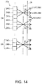
- FIG. 14 illustrates a multiple viewpoint display device 20 a as a variation of the multiple viewpoint display device described above. Note that like parts in this multiple viewpoint display device 20 a and the multiple viewpoint display device 20 described above are identified by like reference numerals and further description thereof is omitted.
- This multiple viewpoint display device 20 a has a slit screen 27 disposed in front of the pixels 24 .
- the slit screen 27 has slits 28 that pass only the rays LAA, LAB, LAC of light emitted from the pixel rows 24 A, 24 B, 24 C in a specific direction.
- the rays LAA for forming the first image LMA are directed to viewpoint A
- the rays LAB for forming the second image LMB are directed to viewpoint B
- rays LAC for forming the third image LMC are direction to viewpoint C. Display images corresponding to different viewpoints A, B, C can also be presented on the multiple viewpoint display device 20 a in this configuration.
- the foregoing multiple viewpoint display devices 20 , 20 a are described presenting display images IM corresponding to three viewpoints A, B, C, but the number of viewpoints is not so limited.
- the multiple viewpoint display devices 20 , 20 a may correspond to more viewpoints than the number of persons participating in a meeting, for example.
- display images IM can be presented for viewing the multiple viewpoint display device 20 from twelve different directions.
- display images IM corresponding to viewpoints at an interval of 10 degrees can be displayed when the effective viewing angle is 120 degrees, for example, display images IM can be presented naturally even when the person viewing the display screen 29 of the multiple viewpoint display device 20 moves to a different viewpoint position.
- the foregoing multiple viewpoint display device 20 is described using the example of a direct-view display device, but can also be used with projection display devices such as projectors, for example.
- projection display devices such as projectors
- projectors corresponding to at least the number of viewpoints are set up to project display images IM from the background of a person to a retroreflective screen.
- the display device described in PTL 3 may also be used as the multiple viewpoint display device 20 .
- the method of setting the parameters used to generate the viewpoint images FMW is not limited to the method of the foregoing embodiment.
- a variation of the method of setting parameters 751 is described below.
- FIG. 15 illustrates this variation of a parameter setting method.
- FIG. 16 is a flow chart of the parameter setting process.
- a virtual space VS having a same multiple viewpoint display device 20 disposed between the person 12 on the transmission side 10 and the persons 32 A, 32 B, 32 C on the reception side 30 can be imagined.
- the parameter setting process can be simplified as described below. Note that the reference line of sight LS and the specific line of sight LB of the person 12 to person 32 B is the same in FIG. 15 as in FIG. 12 .
- the reception side 30 determines the orientation of the person 12 on the transmission side 10 (step S 40 ). This the same as step S 30 in FIG. 11 described above.
- step S 40 supposing the person 12 on the transmission side 10 is facing the direction of a specific person on the reception side 30 (such as person 32 A), the parameter setting unit 765 analyzes the frame image FMR (equivalent to the image data in step S 42 ) acquired with added depth information from the two imaging device 50 A, 50 B, and by triangulation determines the distance Lx and rotation angle information R (angle ⁇ Aa) (step S 42 ).
- Distance Lx is the distance between the display screen 29 of the multiple viewpoint display device 20 and person 12 .
- the reference point of the person 12 used to measure the distance Lx is the center point between the eyes of the person 12 in this example.
- step S 44 determines whether or not the rotation angle information R was calculated for another person on the reception side 30 (such as person 32 C) (step S 44 ). If in step S 44 it is determined that the rotation angle information R was not calculated (step S 44 : NO), step S 40 and step S 42 repeat. In this case, because distance Lx was calculated in the previous iteration of step s 42 , the rotation angle information R may be calculated the next time step S 42 executes with calculating distance Lx.
- step S 44 If in step S 44 it is determined that rotation angle information R was also calculated for another person (step S 44 : YES), the parameter setting unit 765 calculates a subject movement vector VL from the distance Lx and the rotation angle information R related to each persons 32 A, 32 B, 32 C on the reception side 30 (step S 46 ). After step S 46 , the parameter setting unit 765 stores the calculated subject movement vector VL and rotation angle information R as parameters in RAM 75 (step S 48 ).
- the subject movement vector VL is a parameter for moving the image of a person for which there was a perspective transformation in the screen coordinate system relative to the background image.
- FIG. 17 illustrates a display image IMAa presented using the parameters set in the parameter setting process according to this variation. This is described using the display image IMAa displayed by pixel rows 24 A in FIG. 17 .
- the multiple viewpoint image generator 762 generates a viewpoint image FMWA corresponding to viewpoint A.
- This viewpoint images FMWA includes location information determined based on the subject movement vector VL for the viewpoint image FMWA relative to the background image FMV.
- the viewpoint image FMWA of the person 12 when the subject movement vector VL is 0 (zero) is indicated by the dotted lines.
- the multiple viewpoint image generator 762 merges the background image FMV with the viewpoint image FMWA. In this event, the coordinate position of the viewpoint image FMWA in the screen coordinate system is moved only subject movement vector VL.
- Presence can be further improved in this case because the position of the viewpoint image FMWA relative to the background image FMV can be changed according to the position of the viewpoint A, B, C.
- the size of the display area of the multiple viewpoint display devices 20 on the transmission side 10 and the reception side 30 may differ. This configuration supposes that the multiple viewpoint display device 20 is treated like a glass window, and the person 12 on the transmission side 10 and the persons 32 A, 32 B, 32 C on the reception side 30 observing a virtual space VS with the window therebetween.
- a viewpoint image corresponding to the position of the single person may be generated by determining the location of the person. Because when the image communication system 100 is a video conferencing system there is also an imaging device for sending display images from the reception side 30 to the transmission side 10 , the location of the person can be easily determined by the receiver-side information processing device 70 analyzing the image from the imaging device.
- both location 10 and location 30 transmit images to the other side.
- an imaging devices 50 having a microphone and camera is disposed on the right and left sides of the multiple viewpoint display device 20
- a multiple viewpoint display device 20 is installed in both locations 10 and 30
- the communicator 62 on the location 10 side transmits a three-dimensional model FMT of the subject imaged by the imaging devices 50 on the location 10 side to the communicator 72 on the location 30 side.
- the communicator 62 on the location 30 side sends the three-dimensional model FMT of the subject imaged by the imaging devices 50 on the location 30 side to the communicator 72 of on the location 10 side.
- the image communication system 100 described above is not limited to video conferencing systems, and can be used in many other ways.
- the image communication system 100 may be applied in schools for remote learning classes.
- a teacher displayed on screen may point to and select a student on the reception side.
- the transmission side 10 may also be applied to foreign language classes. This enables learning a foreign language from a popular teacher in a remote location. This is convenient for learning a foreign language because classes can be held with a real sense of presence.
- the multiple viewpoint display device 20 may present different display images for the right and left eyes of a person. This further improves presence because a three-dimensional image can be presented for each person in the display images of the multiple viewpoint display device 20 .
- the foregoing embodiments have a depth sensor 54 in the imaging devices 50 , but the depth sensor 54 may be omitted.
- the three-dimensional model generator 665 calculates the depth information and generates the three-dimensional model FMT by triangulation based on images acquired from multiple cameras 52 disposed to different positions.
- the extractor 664 also calculates the depth information, and extracts the subject image and background image by triangulation based on images acquired from multiple cameras 52 disposed to different positions.
- the parameter setting method is based on the line of sight of the person 12 in the embodiments described above, but may be set according to the direction of a subject other than a person.
- a marker such as a rod is applied to the subject, and the parameters are set using the direction the marker is facing as the line of sight.
- the image communication system 100 described above is not limited to video conferencing systems, and can be used in many other ways.
- the image communication system 100 may be used in a store.
- This configuration enables opening more virtual stores than the number of actual stores, and enables a chain of stores nationwide. Unlike simply relaying images of a store, this configuration also enables realistic customer interaction with the expectation of increasing sales.
- the image communication system 100 described above is not limited to video conferencing systems, and can be used in many other ways.
- the image communication system 100 may be used in amusement parks and other attractions.
- an attraction providing a virtual experience enabling multiple participants to ride a single ride, each participant can experience the ride from a different point of view.
- an enemy's direction of attach can be realistically presented. A more realistic experience can thus be enjoyed.
- the image communication system 100 described above is not limited to video conferencing systems, and can be used in many other ways.
- the image communication system 100 may be used in a party setting.
- This configuration enables participating in a party in one location from a remote location. Unlike simply relaying video, this configuration enables participants in the remote location to enjoy a realistic presence.
- this configuration enables participants in both locations to enjoy the same food and drink.
- the image communication system 100 described above is not limited to video conferencing systems, and can be used in many other ways.
- the image communication system 100 may be used for public viewing of a sports or theater event. Unlike simply relaying video, this configuration enables experiencing a public viewing with a realistic sense of presence.
Landscapes
- Engineering & Computer Science (AREA)
- Multimedia (AREA)
- Signal Processing (AREA)
- Physics & Mathematics (AREA)
- General Physics & Mathematics (AREA)
- Computer Graphics (AREA)
- Theoretical Computer Science (AREA)
- Computer Hardware Design (AREA)
- Geometry (AREA)
- Software Systems (AREA)
- Processing Or Creating Images (AREA)
- Controls And Circuits For Display Device (AREA)
- Testing, Inspecting, Measuring Of Stereoscopic Televisions And Televisions (AREA)
Abstract
Description
where X, Y, Z on the left side are the coordinates of the three-dimensional model in the viewing coordinate system; P on the right side is a 3×3 rotation matrix; Xw, Yw, Zw on the right side are locations in space in the world coordinate system; and t in the second term on the right side is a translation vector.
where α is the angle around the X-axis, β is the angle around the Y-axis, and γ is the angle around the Z-axis.
where tx, ty, tz are translation vectors of the X-axis component, Y-axis component, and Z-axis component.
- 10 transmission side
- 12 person
- 13 background object
- 20, 20 a multiple viewpoint display device
- 24 pixels
- 24A, 24B, 24C pixel rows
- 26 lenticular lens
- 27 slit screen
- 28 slits
- 29 display screen
- 30 reception side
- 32A, 32B, 32C person
- 33 background object
- 40 speakers
- 50, 50A, 50B imaging device
- 52 camera
- 54 depth sensor
- 56 microphone
- 60 transmission-side information processing device
- 62 communicator
- 64 ROM
- 65 RAM
- 66 CPU
- 70 receiver-side information processing device
- 72 communicator
- 74 ROM
- 75 RAM
- 76 CPU
- 78 input device
- 100 image communication system
- 662 imaging controller
- 664 extractor
- 665 three-dimensional model generator
- 751 parameters
- 762 multiple viewpoint image generator
- 764 display controller
- 765 parameter setting unit
- A, B, C viewpoint
- FMR frame image
- FMT three-dimensional model
- FMV background image
- FMWA, FMWB, FMWC viewpoint image
- IMA, IMB, IMC, IMAa display image
- LA, LB, LC specific line of sight
- LAA, LAB, LAC rays
- LMA first image
- LMB second image
- LMC third image
- LS reference line of sight
- Lx distance
- R, RA, RB, RC rotation angle information
- SD audio information
- VL subject movement vector
- VS virtual space
- t translation vector information
Claims (4)
Applications Claiming Priority (5)
| Application Number | Priority Date | Filing Date | Title |
|---|---|---|---|
| JP2015235452 | 2015-12-02 | ||
| JP2015-235452 | 2015-12-02 | ||
| JP2016-059671 | 2016-03-24 | ||
| JP2016059671 | 2016-03-24 | ||
| PCT/JP2016/084425 WO2017094543A1 (en) | 2015-12-02 | 2016-11-21 | Information processing device, information processing system, method for controlling information processing device, and method for setting parameter |
Publications (2)
| Publication Number | Publication Date |
|---|---|
| US20180367787A1 US20180367787A1 (en) | 2018-12-20 |
| US10701344B2 true US10701344B2 (en) | 2020-06-30 |
Family
ID=58797264
Family Applications (1)
| Application Number | Title | Priority Date | Filing Date |
|---|---|---|---|
| US15/780,148 Active US10701344B2 (en) | 2015-12-02 | 2016-11-21 | Information processing device, information processing system, control method of an information processing device, and parameter setting method |
Country Status (3)
| Country | Link |
|---|---|
| US (1) | US10701344B2 (en) |
| JP (1) | JPWO2017094543A1 (en) |
| WO (1) | WO2017094543A1 (en) |
Cited By (1)
| Publication number | Priority date | Publication date | Assignee | Title |
|---|---|---|---|---|
| US10869019B2 (en) * | 2019-01-22 | 2020-12-15 | Syscon Engineering Co., Ltd. | Dual depth camera module without blind spot |
Families Citing this family (12)
| Publication number | Priority date | Publication date | Assignee | Title |
|---|---|---|---|---|
| US10986401B2 (en) * | 2016-05-13 | 2021-04-20 | Sony Corporation | Image processing apparatus, image processing system, and image processing method |
| JP6976719B2 (en) * | 2017-05-25 | 2021-12-08 | キヤノン株式会社 | Display control device, display control method and program |
| WO2019107180A1 (en) | 2017-12-01 | 2019-06-06 | ソニー株式会社 | Coding device, coding method, decoding device, and decoding method |
| JP7285834B2 (en) * | 2018-06-19 | 2023-06-02 | パナソニック インテレクチュアル プロパティ コーポレーション オブ アメリカ | Three-dimensional reconstruction method and three-dimensional reconstruction apparatus |
| JP6677852B1 (en) * | 2019-11-01 | 2020-04-08 | 東京瓦斯株式会社 | Information processing system, information processing apparatus and program |
| JP2021194259A (en) * | 2020-06-15 | 2021-12-27 | 任天堂株式会社 | Information processing program, information processing device, information processing system, and information processing method |
| JP2022042153A (en) * | 2020-09-02 | 2022-03-14 | 株式会社クレッセント | Three-dimensional shooting model generation system and three-dimensional shooting model generation method |
| JP2022106474A (en) * | 2021-01-07 | 2022-07-20 | セイコーエプソン株式会社 | Image processing apparatus, image processing method, three-dimensional object forming apparatus, and computer program |
| CN114927027B (en) * | 2022-05-24 | 2024-05-03 | 洛阳理工学院 | Singing training system |
| US20240119619A1 (en) * | 2022-10-05 | 2024-04-11 | Microsoft Technology Licensing, Llc | Deep aperture |
| WO2024095358A1 (en) * | 2022-11-01 | 2024-05-10 | 株式会社バーチャルウインドウ | Image display system and display device |
| WO2024095357A1 (en) * | 2022-11-01 | 2024-05-10 | 株式会社バーチャルウインドウ | Video system |
Citations (13)
| Publication number | Priority date | Publication date | Assignee | Title |
|---|---|---|---|---|
| JPH0522722A (en) | 1991-07-12 | 1993-01-29 | Nippon Telegr & Teleph Corp <Ntt> | Input/ouptup equipment for image communication |
| JPH07182535A (en) | 1993-12-24 | 1995-07-21 | Olympus Optical Co Ltd | Three-dimensional volume data display device |
| US6195116B1 (en) * | 1998-05-22 | 2001-02-27 | Samsung Electronics Co., Ltd. | Multi-point video conferencing system and method for implementing the same |
| JP2009092786A (en) | 2007-10-05 | 2009-04-30 | National Institute Of Information & Communication Technology | Stereoscopic display system |
| JP2013025106A (en) | 2011-07-21 | 2013-02-04 | Toshiba Corp | Image processing system, device, method, and medical image diagnostic device |
| US20130044191A1 (en) * | 2011-06-10 | 2013-02-21 | Panasonic Corporation | Device and method for generating stereoscopic image |
| JP2013074598A (en) | 2011-09-29 | 2013-04-22 | Oki Electric Ind Co Ltd | Image communication apparatus, image communication method, program, and image communication system |
| US20140098183A1 (en) * | 2012-10-10 | 2014-04-10 | Microsoft Corporation | Controlled three-dimensional communication endpoint |
| US20140104368A1 (en) * | 2011-07-06 | 2014-04-17 | Kar-Han Tan | Telepresence portal system |
| JP2014072880A (en) | 2012-10-02 | 2014-04-21 | Nippon Telegr & Teleph Corp <Ntt> | Video communication system and video communication method |
| US20150049011A1 (en) * | 2013-08-15 | 2015-02-19 | Blackberry Limited | Method and apparatus for enhancing three-dimensional image processing |
| US9332218B2 (en) * | 2012-05-31 | 2016-05-03 | Microsoft Technology Licensing, Llc | Perspective-correct communication window with motion parallax |
| US9438891B2 (en) | 2014-03-13 | 2016-09-06 | Seiko Epson Corporation | Holocam systems and methods |
Family Cites Families (5)
| Publication number | Priority date | Publication date | Assignee | Title |
|---|---|---|---|---|
| JPH0714208B2 (en) * | 1989-07-04 | 1995-02-15 | 株式会社テレマティーク国際研究所 | Video transmission system |
| JPH04241594A (en) * | 1991-01-14 | 1992-08-28 | Mitsubishi Electric Corp | Binocular parallax information compressing system for stereoscopic image tv telephone set |
| JP2001092990A (en) * | 1999-09-20 | 2001-04-06 | Nippon Telegr & Teleph Corp <Ntt> | Three-dimensional virtual space participant display method, three-dimensional virtual space display device and recording medium stored with three-dimensional virtual space participant display program |
| US6573912B1 (en) * | 2000-11-07 | 2003-06-03 | Zaxel Systems, Inc. | Internet system for virtual telepresence |
| JP5478357B2 (en) * | 2010-05-14 | 2014-04-23 | 日本電信電話株式会社 | Display device and display method |
-
2016
- 2016-11-21 JP JP2017521598A patent/JPWO2017094543A1/en active Pending
- 2016-11-21 WO PCT/JP2016/084425 patent/WO2017094543A1/en active Application Filing
- 2016-11-21 US US15/780,148 patent/US10701344B2/en active Active
Patent Citations (14)
| Publication number | Priority date | Publication date | Assignee | Title |
|---|---|---|---|---|
| JPH0522722A (en) | 1991-07-12 | 1993-01-29 | Nippon Telegr & Teleph Corp <Ntt> | Input/ouptup equipment for image communication |
| JPH07182535A (en) | 1993-12-24 | 1995-07-21 | Olympus Optical Co Ltd | Three-dimensional volume data display device |
| US6195116B1 (en) * | 1998-05-22 | 2001-02-27 | Samsung Electronics Co., Ltd. | Multi-point video conferencing system and method for implementing the same |
| JP2009092786A (en) | 2007-10-05 | 2009-04-30 | National Institute Of Information & Communication Technology | Stereoscopic display system |
| US20130044191A1 (en) * | 2011-06-10 | 2013-02-21 | Panasonic Corporation | Device and method for generating stereoscopic image |
| US20140104368A1 (en) * | 2011-07-06 | 2014-04-17 | Kar-Han Tan | Telepresence portal system |
| US20130181979A1 (en) | 2011-07-21 | 2013-07-18 | Toshiba Medical Systems Corporation | Image processing system, apparatus, and method and medical image diagnosis apparatus |
| JP2013025106A (en) | 2011-07-21 | 2013-02-04 | Toshiba Corp | Image processing system, device, method, and medical image diagnostic device |
| JP2013074598A (en) | 2011-09-29 | 2013-04-22 | Oki Electric Ind Co Ltd | Image communication apparatus, image communication method, program, and image communication system |
| US9332218B2 (en) * | 2012-05-31 | 2016-05-03 | Microsoft Technology Licensing, Llc | Perspective-correct communication window with motion parallax |
| JP2014072880A (en) | 2012-10-02 | 2014-04-21 | Nippon Telegr & Teleph Corp <Ntt> | Video communication system and video communication method |
| US20140098183A1 (en) * | 2012-10-10 | 2014-04-10 | Microsoft Corporation | Controlled three-dimensional communication endpoint |
| US20150049011A1 (en) * | 2013-08-15 | 2015-02-19 | Blackberry Limited | Method and apparatus for enhancing three-dimensional image processing |
| US9438891B2 (en) | 2014-03-13 | 2016-09-06 | Seiko Epson Corporation | Holocam systems and methods |
Non-Patent Citations (3)
| Title |
|---|
| "Super Realistic Telework Office," ITmedia, Jul. 16, 2015, [http://www.itmedia.co.jp/enterprise/articles/1507/16/news047 html]. |
| Feb. 14, 2017 International Search Report issued International Patent Application No. PCT/JP2016/084425. |
| Yatsuduka, Eri, "Keys to Successful Telework," ITmedia, Mar. 24, 2015, [http://www.itmedia.co.jp/enterprise/articles/1503/24/news011.html]. |
Cited By (1)
| Publication number | Priority date | Publication date | Assignee | Title |
|---|---|---|---|---|
| US10869019B2 (en) * | 2019-01-22 | 2020-12-15 | Syscon Engineering Co., Ltd. | Dual depth camera module without blind spot |
Also Published As
| Publication number | Publication date |
|---|---|
| WO2017094543A1 (en) | 2017-06-08 |
| JPWO2017094543A1 (en) | 2018-09-20 |
| US20180367787A1 (en) | 2018-12-20 |
Similar Documents
| Publication | Publication Date | Title |
|---|---|---|
| US10701344B2 (en) | Information processing device, information processing system, control method of an information processing device, and parameter setting method | |
| US10109113B2 (en) | Pattern and method of virtual reality system based on mobile devices | |
| Beck et al. | Immersive group-to-group telepresence | |
| US9317956B2 (en) | Apparatus and method for providing mixed reality contents for learning through story-based virtual experience | |
| US20130225305A1 (en) | Expanded 3d space-based virtual sports simulation system | |
| EP1686554A2 (en) | Virtual space generating system, image processing apparatus and information processing method | |
| US20050264858A1 (en) | Multi-plane horizontal perspective display | |
| JP7073481B2 (en) | Image display system | |
| CN102540464A (en) | Head-mounted display device which provides surround video | |
| CN109358754B (en) | Mixed reality head-mounted display system | |
| WO2017065348A1 (en) | Collaboration method using head mounted display | |
| US20130201099A1 (en) | Method and system for providing a modified display image augmented for various viewing angles | |
| WO2014108799A2 (en) | Apparatus and methods of real time presenting 3d visual effects with stereopsis more realistically and substract reality with external display(s) | |
| EP3913478A1 (en) | Systems and methods for facilitating shared rendering | |
| Caarls et al. | Augmented reality for art, design and cultural heritage—system design and evaluation | |
| Noh et al. | An HMD-based Mixed Reality System for Avatar-Mediated Remote Collaboration with Bare-hand Interaction. | |
| CN210609485U (en) | Real-time interactive virtual reality view sharing system | |
| CN114371779A (en) | Visual enhancement method for sight depth guidance | |
| WO2022023142A1 (en) | Virtual window | |
| CN113941138A (en) | AR interaction control system, device and application | |
| Minatani et al. | Face-to-face tabletop remote collaboration in mixed reality | |
| CN111881807A (en) | VR conference control system and method based on face modeling and expression tracking | |
| CN111345037B (en) | Virtual reality image providing method and program using the same | |
| Lu et al. | An immersive telepresence system using rgb-d sensors and head mounted display | |
| Li | Development of immersive and interactive virtual reality environment for two-player table tennis |
Legal Events
| Date | Code | Title | Description |
|---|---|---|---|
| AS | Assignment |
Owner name: SEIKO EPSON CORPORATION, JAPAN Free format text: ASSIGNMENT OF ASSIGNORS INTEREST;ASSIGNORS:NAKAJIMA, YASUMASA;MATSUSHITA, HIROSHI;MOKUYA, SENICHI;SIGNING DATES FROM 20180502 TO 20180517;REEL/FRAME:045939/0045 |
|
| FEPP | Fee payment procedure |
Free format text: ENTITY STATUS SET TO UNDISCOUNTED (ORIGINAL EVENT CODE: BIG.); ENTITY STATUS OF PATENT OWNER: LARGE ENTITY |
|
| STPP | Information on status: patent application and granting procedure in general |
Free format text: DOCKETED NEW CASE - READY FOR EXAMINATION |
|
| STPP | Information on status: patent application and granting procedure in general |
Free format text: NON FINAL ACTION MAILED |
|
| STPP | Information on status: patent application and granting procedure in general |
Free format text: RESPONSE TO NON-FINAL OFFICE ACTION ENTERED AND FORWARDED TO EXAMINER |
|
| STPP | Information on status: patent application and granting procedure in general |
Free format text: FINAL REJECTION MAILED |
|
| STPP | Information on status: patent application and granting procedure in general |
Free format text: NOTICE OF ALLOWANCE MAILED -- APPLICATION RECEIVED IN OFFICE OF PUBLICATIONS |
|
| STCF | Information on status: patent grant |
Free format text: PATENTED CASE |
|
| MAFP | Maintenance fee payment |
Free format text: PAYMENT OF MAINTENANCE FEE, 4TH YEAR, LARGE ENTITY (ORIGINAL EVENT CODE: M1551); ENTITY STATUS OF PATENT OWNER: LARGE ENTITY Year of fee payment: 4 |