US10693343B2 - Electrostatic generator/motor electrodes located on the inner surface of an electromechanical battery rotor - Google Patents
Electrostatic generator/motor electrodes located on the inner surface of an electromechanical battery rotor Download PDFInfo
- Publication number
- US10693343B2 US10693343B2 US16/401,994 US201916401994A US10693343B2 US 10693343 B2 US10693343 B2 US 10693343B2 US 201916401994 A US201916401994 A US 201916401994A US 10693343 B2 US10693343 B2 US 10693343B2
- Authority
- US
- United States
- Prior art keywords
- rotor
- rings
- electrodes
- aor
- electrode
- Prior art date
- Legal status (The legal status is an assumption and is not a legal conclusion. Google has not performed a legal analysis and makes no representation as to the accuracy of the status listed.)
- Active
Links
Images


Classifications
-
- H—ELECTRICITY
- H02—GENERATION; CONVERSION OR DISTRIBUTION OF ELECTRIC POWER
- H02K—DYNAMO-ELECTRIC MACHINES
- H02K7/00—Arrangements for handling mechanical energy structurally associated with dynamo-electric machines, e.g. structural association with mechanical driving motors or auxiliary dynamo-electric machines
- H02K7/02—Additional mass for increasing inertia, e.g. flywheels
- H02K7/025—Additional mass for increasing inertia, e.g. flywheels for power storage
-
- H—ELECTRICITY
- H01—ELECTRIC ELEMENTS
- H01M—PROCESSES OR MEANS, e.g. BATTERIES, FOR THE DIRECT CONVERSION OF CHEMICAL ENERGY INTO ELECTRICAL ENERGY
- H01M14/00—Electrochemical current or voltage generators not provided for in groups H01M6/00 - H01M12/00; Manufacture thereof
-
- H—ELECTRICITY
- H02—GENERATION; CONVERSION OR DISTRIBUTION OF ELECTRIC POWER
- H02N—ELECTRIC MACHINES NOT OTHERWISE PROVIDED FOR
- H02N1/00—Electrostatic generators or motors using a solid moving electrostatic charge carrier
- H02N1/06—Influence generators
- H02N1/08—Influence generators with conductive charge carrier, i.e. capacitor machines
-
- Y—GENERAL TAGGING OF NEW TECHNOLOGICAL DEVELOPMENTS; GENERAL TAGGING OF CROSS-SECTIONAL TECHNOLOGIES SPANNING OVER SEVERAL SECTIONS OF THE IPC; TECHNICAL SUBJECTS COVERED BY FORMER USPC CROSS-REFERENCE ART COLLECTIONS [XRACs] AND DIGESTS
- Y02—TECHNOLOGIES OR APPLICATIONS FOR MITIGATION OR ADAPTATION AGAINST CLIMATE CHANGE
- Y02E—REDUCTION OF GREENHOUSE GAS [GHG] EMISSIONS, RELATED TO ENERGY GENERATION, TRANSMISSION OR DISTRIBUTION
- Y02E60/00—Enabling technologies; Technologies with a potential or indirect contribution to GHG emissions mitigation
- Y02E60/16—Mechanical energy storage, e.g. flywheels or pressurised fluids
Definitions
- the present invention relates to electromechanical battery (EMB) electrode design, and more specifically, it relates to means for overcoming the high g load on the rotor electrodes of an EMB.
- EMB electromechanical battery
- the electrodes of such modules must withstand very high centrifugal forces. This situation is particularly evident for small rotors (e.g., diameters of 10 cm or less) that may operate at speeds in excess of 200,000 RPM.
- the centrifugal force at the inner surface of the rotor may be of in excess of a million g, implying that an item weighing only 1 gram on the inner surface of the rotor will have an equivalent weight of over 1 metric ton. Since even the lightest electrode structure for the rotor can be expected to weigh tens of grams, its equivalent “weight” can be of order 10 to 100 metric tons.
- This invention pertains to the geometric design of E-S generator/motor electrodes mounted on the inner surface of a fiber-composite rotor.
- the centrifugal g-forces are very high so that the E-S rotor electrode design must be such as to be able to sustain these forces.
- the rotor is fabricated from carbon-fiber composite, its electrical conductivity would interfere with the proper operation of the E-S generator/motor electrodes. Since carbon-fiber rotors are commonly wound on top of an inner E or S-glass fiber composite core, mounting the electrodes on the inner surface both can solve the high-g problem and the carbon-fiber conductivity problem. The issue then is to achieve the needed area to satisfy the power requirements of the storage system.
- This problem is most evident in vehicular applications.
- This invention pertains to a design that employs a stacked wedge-like electrode array that both solves the high-g problem and results in a doubling or tripling of the electrode area, relative to that of electrodes that conform to the inner cylindrical surface of the rotor.
- the invention can be used in flywheel storage systems or other rotating machinery, including for vehicular or stationary use.
- FIG. 1A is a schematic section drawing of an EMB rotor comprising a carbon fiber wound on top of an inner E- or S-glass fiber composite core with rotor electrode support rings on the inside surface of the rotor.
- FIG. 1B is a schematic section drawing of an electrically non-conducting EMB rotor with rotor electrode support rings on the inside surface of the rotor.
- FIG. 1C is a schematic section drawing of an EMB rotor comprising a carbon fiber wound on top of an inner E- or S-glass fiber composite core, where the inner core has been machined to form slots.
- FIG. 1D is a schematic section drawing of an electrically non-conducting EMB rotor where its inner surface has been machined to form slots.
- FIG. 2 is a schematic section drawing of a stator electrode end.
- FIG. 3A shows a rotor section of FIG. 1 and shows an upper stator section and a lower stator section where each stator includes arrays of the electrodes of FIG. 2 .
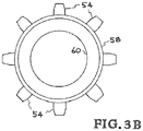
- FIG. 3B shows an axial view of the stator of FIG. 3A
- high-strength fibers are embedded in an epoxy matrix.
- the fibers used include E-glass and the higher-strength S-Glass, basalt fibers, and carbon fibers such as IMS65 and the highest strength carbon fiber, T1000 (tensile strength 7 Gpa, i.e., about 1 million psi).
- T1000 tensile strength 7 Gpa, i.e., about 1 million psi.
- the innermost composite layers are made using S-glass instead of carbon fiber.
- This two-layer design is employed because carbon-fiber composites are highly sensitive to the presence of point loads, while S-Glass composites are much less sensitive. Centrifugal stresses within the S-glass composite are transferred in part to the high-modulus carbon-fiber composite so that the S-glass is not stressed above its safe working limit.
- the first circumstance implies that when the outer part of the rotor body is composed of carbon-fiber composite, its electrical conductivity precludes the location of the conducting strips required for the electrodes on the outer surface of the rotor. In such a case, the conductivity of that part of the rotor surface lying between the strips would greatly vitiate the performance of the E-S generator.
- these electrodes must be located on the inner surface of the rotor, and that inner part of the rotor must be non-conducting, i.e., it must be composed of glass or basalt fiber composite.
- the next issue faced by the designer is to insure that the electrode area is sufficiently large to generate the power required by the application. If the application of the EMB is the bulk storage of energy, with hours-long charging and discharging times, then simple designs can be used. An example would be to use vertical strips of metal foil or metallic coating on the inner surface of the rotor. However, if the peak power demands are substantially higher, as they would be in vehicular applications, for example, then a higher electrode area would likely be required.
- the invention thus addresses two issues: (1) Dealing with high-g centrifugal force fields, and (2) Increasing the electrical capacitance and the max/min capacity ratio of the E-S electrode system.
- FIGS. 1 and 2 The basic concept of the new system is illustrated schematically in the section views shown in FIGS. 1 and 2 .
- FIG. 1A shows a sectional view of hollow cylindrical rotor 10 , which is formed of a non-conducting core 12 within a carbon fiber composite 14 .
- the inner surface of the rotor 10 has been configured to include multiple vertically spaced cells 16 , bounded on their upper and lower surfaces by wedge-shaped fiber-composite separator rings 18 .
- One exemplary embodiment of the rings is formed of G-10 glass and another is formed of fiberglass. Other embodiments are possible.
- a configuration of cells is achieved by assembling a stack of fiber-composite rings of the proper shape within the inside surface of the glass or basalt fiber-composite inner portion of the rotor.
- the separators are made wedge-shaped instead of being constructed as constant-thickness discs in order to minimize the compressive stresses that will occur at their bases; however, other shapes are within the scope of the invention. Note that is can be beneficial to make the tips of the rings 18 to be rounded rather than points pointed tips tend to have a lower breakdown voltage. Likewise, the troughs of the cells can benefit from having rounded corners rather than sharp corners. This same principle applies to all of the electrode configurations described herein. Keeping these stresses within their limiting value will also determine the maximum value of the ratio of the outer radius of these rings to their inner radius.
- FIG. 1B is a sectional view that shows a configuration where rotor 11 is conductive and where the inner non-conducting core of FIG. 1A is omitted.
- FIG. 1C An alternate configuration of cells can be achieved by machining slots on the inner surface of the rotor as shown in the sectional view of FIG. 1C .
- the inner surface is machined in an electrically non-conducting core 20 around which is wound a carbon fiber composite 22 .
- the core 20 can beneficially have all rounded or beveled corners to increase the electrical breakdown voltage.
- FIG. 1D is a sectional view that shows another rotor configuration having slots machined on the inner surface.
- the entire rotor 30 is formed of electrically non-conducting material.
- the core 20 can beneficially have all rounded or beveled corners to increase the electrical breakdown voltage. As much as possible, the contour of the peaks and troughs should be uniform.
- FIG. 2 shows a side sectional view of a “blade” 40 of the stator.
- the figure shows the blade as having corners, it is beneficial if the edges that face the rotor electrodes are rounded or beveled. It is beneficial to have a rounded top, rather than a flat top.
- the new conductor array is can be incorporated into a “balanced circuit” system (See FIG. 15 in U.S. Pat. No. 7,834,513, incorporated herein by reference).
- the rotor electrodes operate in a “virtual ground” situation. That is, the stator is divided into an upper (“plus” charged) section and a lower (“minus” charged) section. See FIG. 3A , described below.
- the E-S generator capacitor is thus divided into an upper and lower half, with the rotor electrodes, which run the full length of the rotor, completing the circuit.
- These electrodes could be made, for example, of vertical strips of metal foil bonded to the inner corrugated surface of the rotor cell structure.
- FIG. 3A shows a sectional view of one side of the rotor 50 which includes the separator rings 52 on which is laid down a conducting strip 53 .
- the rotor is electrically non-conductive.
- the figure also shows an upper series of stator electrode blades 54 and a lower series of stator electrode blades 56 .
- the upper series of blades 54 are in electrical contact with conductive strip 58 , which is attached to stator section 60 .
- the lower series of blades 56 are in electrical contact with conductive strip 62 , which is attached to stator section 64 . Notice the gap 66 between stator section 60 and stator section 64 .
- FIG. 3B shows an axial view of the stator of FIG. 3A and shows rotor 60 , strip 58 and blades 54 . For clarity, a balanced circuit similar to the one shown in FIG. 15 of U.S.
- a source 80 of positive voltage is connected to inductor 82 and resistor 84 and to conductive strip 58 .
- a source 86 of negative voltage is connected to inductor 88 and resistor 90 and to conductive strip 62 .
- the conducting strip 53 is a plating rather than a foil. Such plating can be formed vapor deposition.
- a connection is made from a node 85 between resister 84 and strip 58 to a node 91 between resistor 90 and strip 62 .
- the connection from node 85 is made to a capacitor 94 and to a load 96 to a capacitor 98 to node 91 .
- Assembly of this and similar embodiments can be accomplished by building or stacking the device from one end of the rotor. For example, starting at the bottom of the rotor 50 with reference to the page, a first ring can be attached to the rotor. Then, a blade is attached to the stator. The assembly process is continued up the rotor. They rotor electrode cart be deposited by rotating the rotor such that is does not directly line up with the stator electrodes. It is possible to first fabricate the stator and its blades and then connect the rotor sections around the stator.
- the rotor can be prefabricated and the stator assemble inserted in sections within the inner radius of the cylindrical rotor. Other assembly procedures will be apparent to those skilled in the art based on this disclosure. It is also possible to make the rotor blades to be rings with non-conducting material located along the longitudinal axis of the stator on its outside wall such that there are conducting blades corresponding to the spacing of the rotor electrodes.
Abstract
Description
Claims (14)
Priority Applications (1)
| Application Number | Priority Date | Filing Date | Title |
|---|---|---|---|
| US16/401,994 US10693343B2 (en) | 2015-08-19 | 2019-05-02 | Electrostatic generator/motor electrodes located on the inner surface of an electromechanical battery rotor |
Applications Claiming Priority (3)
| Application Number | Priority Date | Filing Date | Title |
|---|---|---|---|
| US201562207341P | 2015-08-19 | 2015-08-19 | |
| US15/076,472 US10298090B2 (en) | 2015-08-19 | 2016-03-21 | Electrostatic generator/motor electrodes located on the inner surface of an electromechanical battery rotor |
| US16/401,994 US10693343B2 (en) | 2015-08-19 | 2019-05-02 | Electrostatic generator/motor electrodes located on the inner surface of an electromechanical battery rotor |
Related Parent Applications (1)
| Application Number | Title | Priority Date | Filing Date |
|---|---|---|---|
| US15/076,472 Continuation US10298090B2 (en) | 2015-08-19 | 2016-03-21 | Electrostatic generator/motor electrodes located on the inner surface of an electromechanical battery rotor |
Publications (2)
| Publication Number | Publication Date |
|---|---|
| US20190260264A1 US20190260264A1 (en) | 2019-08-22 |
| US10693343B2 true US10693343B2 (en) | 2020-06-23 |
Family
ID=58051949
Family Applications (2)
| Application Number | Title | Priority Date | Filing Date |
|---|---|---|---|
| US15/076,472 Active 2036-12-19 US10298090B2 (en) | 2015-08-19 | 2016-03-21 | Electrostatic generator/motor electrodes located on the inner surface of an electromechanical battery rotor |
| US16/401,994 Active US10693343B2 (en) | 2015-08-19 | 2019-05-02 | Electrostatic generator/motor electrodes located on the inner surface of an electromechanical battery rotor |
Family Applications Before (1)
| Application Number | Title | Priority Date | Filing Date |
|---|---|---|---|
| US15/076,472 Active 2036-12-19 US10298090B2 (en) | 2015-08-19 | 2016-03-21 | Electrostatic generator/motor electrodes located on the inner surface of an electromechanical battery rotor |
Country Status (5)
| Country | Link |
|---|---|
| US (2) | US10298090B2 (en) |
| EP (1) | EP3338358B1 (en) |
| ES (1) | ES2912115T3 (en) |
| PL (1) | PL3338358T3 (en) |
| WO (1) | WO2017030846A1 (en) |
Families Citing this family (3)
| Publication number | Priority date | Publication date | Assignee | Title |
|---|---|---|---|---|
| US10122301B2 (en) * | 2015-08-19 | 2018-11-06 | Lawrence Livermore National Security, Llc | Pulsed start-up system for electrostatic generators |
| US10298090B2 (en) * | 2015-08-19 | 2019-05-21 | Lawrence Livermore National Security, Llc | Electrostatic generator/motor electrodes located on the inner surface of an electromechanical battery rotor |
| WO2019161256A2 (en) | 2018-02-15 | 2019-08-22 | The Charles Stark Draper Laboratory, Inc. | Electrostatic motor |
Citations (30)
| Publication number | Priority date | Publication date | Assignee | Title |
|---|---|---|---|---|
| US2009503A (en) * | 1932-05-06 | 1935-07-30 | Landwerlin Georges | Electrostatic machine |
| US2194839A (en) * | 1937-06-09 | 1940-03-26 | Research Corp | Method of and apparatus for electrostatically generating direct current power |
| US2247783A (en) * | 1937-05-08 | 1941-07-01 | Massolle Joseph | Machine for the production of alternating energy from direct current sources |
| US2486140A (en) * | 1944-11-08 | 1949-10-25 | Centre Nat Rech Scient | Electrostatic generating and driving machine |
| USRE23460E (en) * | 1952-02-12 | Felici | ||
| US3039011A (en) * | 1958-02-03 | 1962-06-12 | High Voltage Engineering Corp | Electrostatic generator |
| US3107326A (en) * | 1960-05-25 | 1963-10-15 | High Voltage Engineering Corp | Variable capacitance electrostatic generator |
| US3143671A (en) * | 1959-07-27 | 1964-08-04 | High Voltage Engineering Corp | Brushless high voltage d. c. electrostatic machine |
| US3700983A (en) * | 1971-06-10 | 1972-10-24 | Itt | Variable capacitor having a solid dielectric between its electrodes |
| US4789802A (en) * | 1987-01-24 | 1988-12-06 | Japan Physitec Co., Ltd. | High voltage, multi-stage electrostatic generator |
| US4870310A (en) * | 1988-03-02 | 1989-09-26 | Triplett Billy R | Portable crash-survivable kinetic energy storage machine |
| US6236127B1 (en) * | 1997-03-11 | 2001-05-22 | Forschungszentrum Karlsruhe Gmbh | Flywheel energy accummulator |
| US20050006980A1 (en) | 2003-07-08 | 2005-01-13 | Horst Robert W. | Electrostatic actuator with fault tolerant electrode structure |
| US6867520B2 (en) * | 2000-05-05 | 2005-03-15 | Bruce A. Jennings | Electro-mechanical battery |
| US20050218741A1 (en) | 2004-03-18 | 2005-10-06 | Wnorowski Edward J Jr | Generators, transformers and stators containing high-strength, laminated, carbon-fiber windings |
| US20100237629A1 (en) * | 2008-01-09 | 2010-09-23 | Velkess, Inc. | Flywheel system |
| US7834513B2 (en) | 2007-09-10 | 2010-11-16 | Lawrence Livermore National Security, Llc | Electrostatic generator/motor having rotors of varying thickness and a central stator electrically connected together into two groups |
| US8264121B2 (en) * | 2007-09-10 | 2012-09-11 | Lawrence Livermore National Security, Llc | Electrostatic generator/motor configurations |
| US20120267974A1 (en) | 2011-04-19 | 2012-10-25 | Advantron Technologies LLC | Electromagnetic motor-generator unit |
| US20130020900A1 (en) | 2011-07-19 | 2013-01-24 | Seiko Epson Corporation | Electromechanical apparatus, robot, and moving body |
| US20140265688A1 (en) | 2013-03-14 | 2014-09-18 | Lawrence Livermore National Security, Llc | Electrostatic stabilizer for a passive magnetic bearing system |
| US9270203B2 (en) * | 2013-03-12 | 2016-02-23 | Lawrence Livermore National Security, Llc | Electrode geometry for electrostatic generators and motors |
| WO2017030846A1 (en) | 2015-08-19 | 2017-02-23 | Lawrence Livermore National Security, Llc | Improved design for electrostatic generator/motor electrodes located on the inner surface of an electromechanical battery rotor |
| US20170054385A1 (en) * | 2015-08-19 | 2017-02-23 | Lawrence Livermore National Security, Llc | Electrostatic generator/motor rotor electrode system suitable for installation on the outer surface of an emb rotor |
| US9614462B2 (en) * | 2007-09-10 | 2017-04-04 | Lawrence Livermore National Security, Llc | Rippled disc electrostatic generator/motor configurations utilizing magnetic insulation |
| US9634551B2 (en) * | 2009-07-09 | 2017-04-25 | Clifford R. Rabal | Direct current brushless motor |
| US20170271943A1 (en) * | 2014-12-02 | 2017-09-21 | Management Services Group, Inc., Doing Business As (DBA) Global Technical Systems | Devices and methods for increasing energy and/or power density in composite flywheel energy storage systems |
| US20170338750A1 (en) * | 2016-05-17 | 2017-11-23 | Wisconsin Alumni Research Foundation | Electrostatic Rotating-Machine Employing Dielectric Substrates with Surface Conductors |
| US20180013331A1 (en) * | 2016-07-05 | 2018-01-11 | Lawrence Livermore National Security, Llc | Electrostatic generator electrode-centering and seismic-isolation system for flywheel-based energy storage modules |
| US9899937B2 (en) * | 2015-01-16 | 2018-02-20 | Wisconsin Alumni Research Foundation | Peg-style electrostatic rotating machine |
Family Cites Families (1)
| Publication number | Priority date | Publication date | Assignee | Title |
|---|---|---|---|---|
| NL6605612A (en) | 1966-04-27 | 1967-10-30 |
-
2016
- 2016-03-21 US US15/076,472 patent/US10298090B2/en active Active
- 2016-08-10 ES ES16837516T patent/ES2912115T3/en active Active
- 2016-08-10 EP EP16837516.0A patent/EP3338358B1/en active Active
- 2016-08-10 WO PCT/US2016/046246 patent/WO2017030846A1/en active Application Filing
- 2016-08-10 PL PL16837516T patent/PL3338358T3/en unknown
-
2019
- 2019-05-02 US US16/401,994 patent/US10693343B2/en active Active
Patent Citations (32)
| Publication number | Priority date | Publication date | Assignee | Title |
|---|---|---|---|---|
| USRE23460E (en) * | 1952-02-12 | Felici | ||
| US2009503A (en) * | 1932-05-06 | 1935-07-30 | Landwerlin Georges | Electrostatic machine |
| US2247783A (en) * | 1937-05-08 | 1941-07-01 | Massolle Joseph | Machine for the production of alternating energy from direct current sources |
| US2194839A (en) * | 1937-06-09 | 1940-03-26 | Research Corp | Method of and apparatus for electrostatically generating direct current power |
| US2486140A (en) * | 1944-11-08 | 1949-10-25 | Centre Nat Rech Scient | Electrostatic generating and driving machine |
| US3039011A (en) * | 1958-02-03 | 1962-06-12 | High Voltage Engineering Corp | Electrostatic generator |
| US3143671A (en) * | 1959-07-27 | 1964-08-04 | High Voltage Engineering Corp | Brushless high voltage d. c. electrostatic machine |
| US3107326A (en) * | 1960-05-25 | 1963-10-15 | High Voltage Engineering Corp | Variable capacitance electrostatic generator |
| US3700983A (en) * | 1971-06-10 | 1972-10-24 | Itt | Variable capacitor having a solid dielectric between its electrodes |
| US4789802A (en) * | 1987-01-24 | 1988-12-06 | Japan Physitec Co., Ltd. | High voltage, multi-stage electrostatic generator |
| US4870310A (en) * | 1988-03-02 | 1989-09-26 | Triplett Billy R | Portable crash-survivable kinetic energy storage machine |
| US6236127B1 (en) * | 1997-03-11 | 2001-05-22 | Forschungszentrum Karlsruhe Gmbh | Flywheel energy accummulator |
| US6867520B2 (en) * | 2000-05-05 | 2005-03-15 | Bruce A. Jennings | Electro-mechanical battery |
| US20050006980A1 (en) | 2003-07-08 | 2005-01-13 | Horst Robert W. | Electrostatic actuator with fault tolerant electrode structure |
| US20050218741A1 (en) | 2004-03-18 | 2005-10-06 | Wnorowski Edward J Jr | Generators, transformers and stators containing high-strength, laminated, carbon-fiber windings |
| US7834513B2 (en) | 2007-09-10 | 2010-11-16 | Lawrence Livermore National Security, Llc | Electrostatic generator/motor having rotors of varying thickness and a central stator electrically connected together into two groups |
| US9614462B2 (en) * | 2007-09-10 | 2017-04-04 | Lawrence Livermore National Security, Llc | Rippled disc electrostatic generator/motor configurations utilizing magnetic insulation |
| US8264121B2 (en) * | 2007-09-10 | 2012-09-11 | Lawrence Livermore National Security, Llc | Electrostatic generator/motor configurations |
| US20100237629A1 (en) * | 2008-01-09 | 2010-09-23 | Velkess, Inc. | Flywheel system |
| US9923501B2 (en) * | 2009-07-09 | 2018-03-20 | Clifford R. Rabal | Direct current brushless motor |
| US9634551B2 (en) * | 2009-07-09 | 2017-04-25 | Clifford R. Rabal | Direct current brushless motor |
| US20120267974A1 (en) | 2011-04-19 | 2012-10-25 | Advantron Technologies LLC | Electromagnetic motor-generator unit |
| US20130020900A1 (en) | 2011-07-19 | 2013-01-24 | Seiko Epson Corporation | Electromechanical apparatus, robot, and moving body |
| US9270203B2 (en) * | 2013-03-12 | 2016-02-23 | Lawrence Livermore National Security, Llc | Electrode geometry for electrostatic generators and motors |
| US20140265688A1 (en) | 2013-03-14 | 2014-09-18 | Lawrence Livermore National Security, Llc | Electrostatic stabilizer for a passive magnetic bearing system |
| US20170271943A1 (en) * | 2014-12-02 | 2017-09-21 | Management Services Group, Inc., Doing Business As (DBA) Global Technical Systems | Devices and methods for increasing energy and/or power density in composite flywheel energy storage systems |
| US9899937B2 (en) * | 2015-01-16 | 2018-02-20 | Wisconsin Alumni Research Foundation | Peg-style electrostatic rotating machine |
| US20170054385A1 (en) * | 2015-08-19 | 2017-02-23 | Lawrence Livermore National Security, Llc | Electrostatic generator/motor rotor electrode system suitable for installation on the outer surface of an emb rotor |
| WO2017030846A1 (en) | 2015-08-19 | 2017-02-23 | Lawrence Livermore National Security, Llc | Improved design for electrostatic generator/motor electrodes located on the inner surface of an electromechanical battery rotor |
| US10298090B2 (en) * | 2015-08-19 | 2019-05-21 | Lawrence Livermore National Security, Llc | Electrostatic generator/motor electrodes located on the inner surface of an electromechanical battery rotor |
| US20170338750A1 (en) * | 2016-05-17 | 2017-11-23 | Wisconsin Alumni Research Foundation | Electrostatic Rotating-Machine Employing Dielectric Substrates with Surface Conductors |
| US20180013331A1 (en) * | 2016-07-05 | 2018-01-11 | Lawrence Livermore National Security, Llc | Electrostatic generator electrode-centering and seismic-isolation system for flywheel-based energy storage modules |
Non-Patent Citations (1)
| Title |
|---|
| International Search Report and Written Opinion for PCT/US16/046246, corresponding to U.S. Appl. No. 15/076,742, 9 pages. |
Also Published As
| Publication number | Publication date |
|---|---|
| PL3338358T3 (en) | 2022-05-30 |
| ES2912115T3 (en) | 2022-05-24 |
| US20190260264A1 (en) | 2019-08-22 |
| EP3338358B1 (en) | 2022-03-16 |
| US20170054343A1 (en) | 2017-02-23 |
| US10298090B2 (en) | 2019-05-21 |
| EP3338358A1 (en) | 2018-06-27 |
| EP3338358A4 (en) | 2019-04-24 |
| WO2017030846A1 (en) | 2017-02-23 |
Similar Documents
| Publication | Publication Date | Title |
|---|---|---|
| US10693343B2 (en) | Electrostatic generator/motor electrodes located on the inner surface of an electromechanical battery rotor | |
| US8264121B2 (en) | Electrostatic generator/motor configurations | |
| US8659874B2 (en) | Energy storage device | |
| US10727763B2 (en) | Method using a electrostatic generator/motor rotor electrode system suitable for installation on the outer surface of an EMB rotor | |
| US8373971B2 (en) | Supercapacitors using nanotube fibers and methods of making the same | |
| CN102656793B (en) | Electrostatic induction power generator | |
| US10102977B2 (en) | High energy density capacitor with micrometer structures and nanometer components | |
| US9614462B2 (en) | Rippled disc electrostatic generator/motor configurations utilizing magnetic insulation | |
| US9129748B2 (en) | Electrostatic capacitor device | |
| CN211859977U (en) | Rotary nano generator and power supply device | |
| EP3836256A1 (en) | Vehicle body member having charging and discharging function | |
| US10903014B2 (en) | High energy density capacitor with high aspect micrometer structures and a giant colossal dielectric material | |
| CN203150391U (en) | Static electric energy storage apparatus | |
| KR102385369B1 (en) | Energy storage device | |
| GB2502904A (en) | Hexagonal Shaped Capacitor | |
| Davis et al. | Channeling of Static Electricity Within Wind Turbines for Transmission into the Power Grid | |
| Aileni et al. | EXPERIMENTAL DESIGN FOR WEARABLE TEXTILE SUPERCAPACITORS | |
| CN116326211A (en) | Lightning protection type wind power generation equipment | |
| BG67018B1 (en) | Device for extraction of atmospheric electricity |
Legal Events
| Date | Code | Title | Description |
|---|---|---|---|
| AS | Assignment |
Owner name: LAWRENCE LIVERMORE NATIONAL SECURITY, LLC, CALIFOR Free format text: ASSIGNMENT OF ASSIGNORS INTEREST;ASSIGNOR:POST, STEPHEN F.;REEL/FRAME:049079/0882 Effective date: 20190430 Owner name: LAWRENCE LIVERMORE NATIONAL SECURITY, LLC, CALIFORNIA Free format text: ASSIGNMENT OF ASSIGNORS INTEREST;ASSIGNOR:POST, STEPHEN F.;REEL/FRAME:049079/0882 Effective date: 20190430 |
|
| FEPP | Fee payment procedure |
Free format text: ENTITY STATUS SET TO UNDISCOUNTED (ORIGINAL EVENT CODE: BIG.); ENTITY STATUS OF PATENT OWNER: LARGE ENTITY |
|
| STPP | Information on status: patent application and granting procedure in general |
Free format text: NON FINAL ACTION MAILED |
|
| STPP | Information on status: patent application and granting procedure in general |
Free format text: NOTICE OF ALLOWANCE MAILED -- APPLICATION RECEIVED IN OFFICE OF PUBLICATIONS |
|
| STPP | Information on status: patent application and granting procedure in general |
Free format text: PUBLICATIONS -- ISSUE FEE PAYMENT VERIFIED |
|
| STCF | Information on status: patent grant |
Free format text: PATENTED CASE |
|
| AS | Assignment |
Owner name: U.S. DEPARTMENT OF ENERGY, DISTRICT OF COLUMBIA Free format text: CONFIRMATORY LICENSE;ASSIGNOR:LAWRENCE LIVERMORE NATIONAL SECURITY, LLC;REEL/FRAME:053969/0121 Effective date: 20201001 |
|
| MAFP | Maintenance fee payment |
Free format text: PAYMENT OF MAINTENANCE FEE, 4TH YEAR, LARGE ENTITY (ORIGINAL EVENT CODE: M1551); ENTITY STATUS OF PATENT OWNER: LARGE ENTITY Year of fee payment: 4 |