US10692235B2 - Image processing apparatus and method for determining a depth of a pixel of a reference image - Google Patents
Image processing apparatus and method for determining a depth of a pixel of a reference image Download PDFInfo
- Publication number
- US10692235B2 US10692235B2 US15/655,841 US201715655841A US10692235B2 US 10692235 B2 US10692235 B2 US 10692235B2 US 201715655841 A US201715655841 A US 201715655841A US 10692235 B2 US10692235 B2 US 10692235B2
- Authority
- US
- United States
- Prior art keywords
- images
- determining
- depth
- subset
- image
- Prior art date
- Legal status (The legal status is an assumption and is not a legal conclusion. Google has not performed a legal analysis and makes no representation as to the accuracy of the status listed.)
- Active, expires
Links
- 238000012545 processing Methods 0.000 title claims abstract description 53
- 238000000034 method Methods 0.000 title claims description 20
- 230000000007 visual effect Effects 0.000 claims abstract description 28
- 238000003672 processing method Methods 0.000 claims description 11
- 230000015654 memory Effects 0.000 description 11
- 238000010586 diagram Methods 0.000 description 9
- 238000004590 computer program Methods 0.000 description 8
- 238000004458 analytical method Methods 0.000 description 3
- 230000005540 biological transmission Effects 0.000 description 3
- 230000006870 function Effects 0.000 description 3
- 238000013459 approach Methods 0.000 description 2
- 230000002457 bidirectional effect Effects 0.000 description 2
- 238000002372 labelling Methods 0.000 description 2
- 238000003909 pattern recognition Methods 0.000 description 2
- 238000012805 post-processing Methods 0.000 description 2
- 238000005070 sampling Methods 0.000 description 2
- 230000026676 system process Effects 0.000 description 2
- 238000012546 transfer Methods 0.000 description 2
- 239000000872 buffer Substances 0.000 description 1
- 238000004364 calculation method Methods 0.000 description 1
- 238000000354 decomposition reaction Methods 0.000 description 1
- 238000006073 displacement reaction Methods 0.000 description 1
- 230000005294 ferromagnetic effect Effects 0.000 description 1
- 238000001914 filtration Methods 0.000 description 1
- 230000010365 information processing Effects 0.000 description 1
- 230000005291 magnetic effect Effects 0.000 description 1
- 230000005055 memory storage Effects 0.000 description 1
- 238000012986 modification Methods 0.000 description 1
- 230000004048 modification Effects 0.000 description 1
- 230000003287 optical effect Effects 0.000 description 1
- 238000005457 optimization Methods 0.000 description 1
- 239000004065 semiconductor Substances 0.000 description 1
- 239000007787 solid Substances 0.000 description 1
Images


Classifications
-
- G—PHYSICS
- G06—COMPUTING; CALCULATING OR COUNTING
- G06T—IMAGE DATA PROCESSING OR GENERATION, IN GENERAL
- G06T7/00—Image analysis
- G06T7/50—Depth or shape recovery
- G06T7/55—Depth or shape recovery from multiple images
- G06T7/557—Depth or shape recovery from multiple images from light fields, e.g. from plenoptic cameras
-
- G—PHYSICS
- G06—COMPUTING; CALCULATING OR COUNTING
- G06T—IMAGE DATA PROCESSING OR GENERATION, IN GENERAL
- G06T7/00—Image analysis
- G06T7/50—Depth or shape recovery
- G06T7/55—Depth or shape recovery from multiple images
- G06T7/593—Depth or shape recovery from multiple images from stereo images
- G06T7/596—Depth or shape recovery from multiple images from stereo images from three or more stereo images
-
- H—ELECTRICITY
- H04—ELECTRIC COMMUNICATION TECHNIQUE
- H04N—PICTORIAL COMMUNICATION, e.g. TELEVISION
- H04N23/00—Cameras or camera modules comprising electronic image sensors; Control thereof
- H04N23/90—Arrangement of cameras or camera modules, e.g. multiple cameras in TV studios or sports stadiums
-
- H04N5/247—
-
- G—PHYSICS
- G06—COMPUTING; CALCULATING OR COUNTING
- G06T—IMAGE DATA PROCESSING OR GENERATION, IN GENERAL
- G06T2200/00—Indexing scheme for image data processing or generation, in general
- G06T2200/21—Indexing scheme for image data processing or generation, in general involving computational photography
-
- G—PHYSICS
- G06—COMPUTING; CALCULATING OR COUNTING
- G06T—IMAGE DATA PROCESSING OR GENERATION, IN GENERAL
- G06T2207/00—Indexing scheme for image analysis or image enhancement
- G06T2207/10—Image acquisition modality
- G06T2207/10028—Range image; Depth image; 3D point clouds
-
- G—PHYSICS
- G06—COMPUTING; CALCULATING OR COUNTING
- G06T—IMAGE DATA PROCESSING OR GENERATION, IN GENERAL
- G06T2207/00—Indexing scheme for image analysis or image enhancement
- G06T2207/10—Image acquisition modality
- G06T2207/10052—Images from lightfield camera
-
- G—PHYSICS
- G06—COMPUTING; CALCULATING OR COUNTING
- G06T—IMAGE DATA PROCESSING OR GENERATION, IN GENERAL
- G06T2207/00—Indexing scheme for image analysis or image enhancement
- G06T2207/20—Special algorithmic details
- G06T2207/20228—Disparity calculation for image-based rendering
Definitions
- the present disclosure relates to an image processing apparatus and method.
- the present disclosure relates to an image processing apparatus and method for determining the depth of a pixel of a reference image of a plurality of images representing a visual scene relative to a plurality of locations.
- a fundamental task in the field of computer vision and computational photography is the estimation of a depth map of a real world visual scene on the basis of a 4D light field thereof, i.e. a plurality of 2D images of the real world visual scene captured on a regular grid of camera positions.
- a 4D light field thereof i.e. a plurality of 2D images of the real world visual scene captured on a regular grid of camera positions.
- the task of estimating a depth map from a 4D light field i.e. a plurality of 2D images of the real world visual scene captured on a regular grid of camera positions
- various challenges such as the accurate depth map estimation of the visual scene at textureless, i.e. uniform color, areas and/or at depth discontinuities.
- textureless i.e. uniform color, areas and/or at depth discontinuities.
- identifying corresponding points of the visual scene across multiple views/images is extremely difficult.
- Current algorithmic solutions tend to over smooth the estimated depth map. Unfortunately, this is the case at objects' boundaries as well as where depth discontinuities are stronger. This results in an inaccurate depth map estimation of the visual scene at those locations.
- the article “Globally Consistent Depth Labeling of 4D Light Fields”, S. Wanner and B. Goldluecke, Computer Vision and Pattern Recognition (CVPR), 2012 describes a method for estimating the depth map of a visual scene via an orientation analysis (based on the so-called structure tensor) of the epipolar images. Each of these images is a 2D cut of the 4D light field.
- the structure tensor analysis provides an initial depth map estimation, i.e. a fast local solution, which then can be further improved by applying a global optimization approach, i.e. a slow global solution. This comes with the cost of added computational complexity.
- the fast local solution can be implemented in real time on standard graphics processing units (GPUs).
- a first depth map is obtained from images whose centers are positioned regularly along the horizontal line passing from the center of the reference image and a second depth map is obtained from the images positioned along the vertical direction.
- the first and the second depth maps are merged to obtain a final depth map, wherein the merging of the first and second depth maps is based on their confidence maps in that for each pixel the depth value with the highest confidence value among the two candidates is chosen.
- the article “Scene Reconstruction from High Spatio-Angular Resolution Light Fields’, SIGGRAPH, 2013 describes an alternative solution for a visual scene reconstruction from 4D light fields which can deal better with uniform color areas while still preserving depth map discontinuities. Also in this case the computational complexity is high and for this reason a real time implementation is not possible.
- the input 4D light field must also be sampled densely enough, which in the case of plenoptic cameras is generally not possible. Also in this case a first depth map is obtained from images whose centers are positioned regularly along the horizontal line passing from the center of the reference image and a second depth map is obtained from the images positioned along the vertical direction.
- the disclosure relates to an image processing apparatus for determining a depth of a pixel of a reference image of a plurality of images representing a visual scene relative to a plurality of locations, wherein the plurality of locations define a two-dimensional regular grid with rows and columns, for instance, a rectangular grid, and wherein the location of the reference image is associated with a reference row and a reference column of the grid.
- the image processing apparatus comprises a depth determiner configured to determine a first depth estimate on the basis of the reference image and a first subset of the plurality of images for determining the depth of the pixel of the reference image, wherein the images of the first subset are associated with locations being associated with at least one row of the grid different than the reference row and with at least one column of the grid different than the reference column.
- the depth determiner is further configured to determine a second depth estimate on the basis of the reference image and a second subset of the plurality of images, wherein the images of the second subset of the plurality of images are associated with locations being associated with the reference row, and wherein the depth determiner is further configured to combine the first depth estimate and the second depth estimate for determining the depth of the pixel of the reference image.
- This implementation form combines in a computationally efficient manner the depth information available from the images lying in the same row as the reference image and images lying in different rows and columns.
- the depth determiner is further configured to determine a third depth estimate on the basis of the reference image and a third subset of the plurality of images, wherein the images of the third subset of the plurality of images are associated with locations being associated with the reference column, and configured to combine the first depth estimate, the second depth estimate and/or the third depth estimate for determining the depth of the pixel of the reference image.
- This implementation form combines in a computationally efficient manner the depth information available from the images lying in the same column as the reference image and images lying in different rows and columns.
- the depth determiner is configured to determine the depth of the pixel of the reference image by computing a median value of the first depth estimate, the second depth estimate and/or the third depth estimate. This implementation form provides a computationally efficient way of determining the depth without having to compute confidence values.
- the depth determiner is configured to determine the first depth estimate, the second depth estimate and/or the third depth estimate by determining the slope of the epipolar line defined by the position of the pixel in the reference image and the positions of the corresponding pixels in the first subset, the second subset or the third subset of the plurality of images, respectively.
- This implementation form yields exceptionally good depth estimates.
- the image processing apparatus further comprises a confidence value determiner, wherein the confidence value determiner is configured to determine a respective confidence value associated with the first depth estimate, the second depth estimate and/or the third depth estimate.
- This implementation form yields very reliable depth estimates.
- the depth determiner is configured to determine the depth of the pixel of the reference image by choosing as the depth of the pixel of the reference image the depth estimate from the group consisting of the first depth estimate, the second depth estimate and/or the third depth estimate having the largest confidence value. This implementation form yields very reliable depth estimates.
- the confidence value determiner is configured to determine the confidence value for the first depth estimate, the second depth estimate and/or the third depth estimate on the basis of a structure tensor defined by the first subset, the second subset and the third subset of the plurality of images, respectively. This implementation form yields very reliable depth estimates.
- the confidence value determiner is configured to exclude a depth estimate on the basis of a filter K defined by the equation:
- K ⁇ ( d ) e - d 2 2 ⁇ ⁇ ⁇ b , where d denotes the disparity of the pixel and b denotes the baseline defined by the reference image and the first subset of the plurality of images.
- This implementation form uses only reliable depth estimates for estimating the depth.
- the depth determiner is configured to determine the depth of the pixel of the reference image on the basis of the first depth estimate by interpolating the intensity of the pixel between the intensity of the pixel in the reference image and the intensities of the corresponding pixels in the first subset of the plurality of images.
- the image processing apparatus further comprises an image recorder configured to record the plurality of images representing the visual scene at the plurality of locations.
- the image recorder comprises a movable camera, an array of cameras or a plenoptic camera.
- the image processing apparatus is configured to determine a depth map for the reference image by determining a depth estimate for a plurality of pixels of the reference image.
- the depth determiner is configured to determine the first depth estimate on the basis of the reference image and the first subset of the plurality of images for determining the depth of the pixel of the reference image, wherein the reference image and the first subset of the plurality of images share a common center pixel.
- the disclosure relates to an image processing method for determining a depth of a pixel of a reference image of a plurality of images representing a visual scene relative to a plurality of locations, the plurality of locations defining a two-dimensional grid with rows and columns, the location of the reference image being associated with a reference row and a reference column of the grid.
- the image processing method comprises the step of determining a first depth estimate on the basis of the reference image and a first subset of the plurality of images for determining the depth of the pixel of the reference image, wherein the images of the first subset are associated with locations being associated with at least one row of the grid different than the reference row and with at least one column of the grid different than the reference column.
- the image processing method according to the second aspect of the disclosure can be performed by the image processing apparatus according to the first aspect of the disclosure. Further features of the image processing method according to the second aspect of the disclosure result directly from the functionality of the image processing apparatus according to the first aspect of the disclosure and its different implementation forms.
- the disclosure relates to a computer program comprising program code for performing the method according to the second aspect of the disclosure when executed on a computer.
- the disclosure can be implemented in hardware and/or software.
- FIG. 1 shows a schematic diagram of an image processing apparatus according to an embodiment
- FIG. 2 shows an illustrative example of a grid of a plurality of images that can be processed by an image processing apparatus and method according to an embodiment
- FIG. 3 shows an illustrative example of a grid of a plurality of images that can be processed by an image processing apparatus and method according to an embodiment
- FIG. 4 shows a schematic diagram illustrating pixel selection in a grid of a plurality of images implemented in an image processing apparatus according to an embodiment
- FIG. 5 shows a schematic diagram illustrating depth estimation implemented in an image processing apparatus according to an embodiment
- FIG. 6 shows a schematic diagram illustrating depth determination implemented in an image processing apparatus according to an embodiment
- FIG. 7 shows a schematic diagram illustrating confidence value determination implemented in an image processing apparatus according to an embodiment
- FIG. 8 shows a schematic diagram illustrating confidence value determination implemented in an image processing apparatus according to an embodiment
- FIG. 9 shows a schematic diagram of an image processing method according to an embodiment.
- a disclosure in connection with a described method may also hold true for a corresponding device or system configured to perform the method and vice versa.
- a corresponding device or apparatus may include a unit to perform the described method step, even if such unit is not explicitly described or illustrated in the figures.
- the features of the various exemplary aspects described herein may be combined with each other, unless specifically noted otherwise.
- FIG. 1 shows a schematic diagram of an image processing apparatus 100 according to an embodiment.
- the image processing apparatus 100 is configured to determine a depth 107 of a pixel of a reference image of a plurality of images representing a visual scene relative to a plurality of locations representing, for instance, camera positions.
- the plurality of locations define a regular two-dimensional grid with rows and columns.
- FIGS. 2 and 3 show an exemplary square-shaped two-dimensional grid 200 of camera positions.
- the central image has been chosen as the reference image 201 for illustration purposes.
- any one image of the plurality of images shown in FIGS. 2 and 3 could be chosen as reference image as well.
- the reference image 201 is located within a reference row 203 and a reference column 205 of the two-dimensional grid 200 .
- the image processing apparatus 100 comprises a depth determiner 101 configured to determine a first depth estimate on the basis of the reference image 201 and a first subset of the plurality of images 105 for determining the depth 107 of the pixel of the reference image 201 , wherein the images of the first subset are associated with locations being associated with at least one row of the grid 200 different than the reference row 203 and with at least one column of the grid 200 different than the reference column 205 .
- the image processing apparatus 100 can comprise an image recorder 102 configured to record the plurality of images 105 representing the visual scene at the plurality of locations.
- the image recorder 102 comprises, for instance, a movable camera, an array of cameras or a plenoptic camera.
- the image processing apparatus 100 is configured to determine a depth map for the reference image 201 by determining a respective depth 107 for a plurality of pixels of the reference image 201 .
- the depth determiner 101 is configured, for instance, to determine a first depth estimate on the basis of the reference image 201 and the subset of the plurality of images 105 of the grid 200 lying along the dashed line 207 shown in FIG. 2 , corresponding to one diagonal of the grid 200 .
- the depth determiner 101 is configured, for instance, to determine a first depth estimate on the basis of the reference image 201 and the subset of the plurality of images 105 of the grid 200 lying along the dashed line 209 shown in FIG. 2 making an angle of less than 45° with a line defined by the reference row 203 of the grid 200 .
- the depth determiner 101 is further configured to determine a second depth estimate on the basis of the reference image 201 and a second subset of the plurality of images 105 , wherein the images of the second subset of the plurality of images 105 are associated with locations being associated with the reference row 203 , and wherein the depth determiner 101 is further configured to combine the first depth estimate and the second depth estimate for determining the depth 107 of the pixel of the reference image.
- the depth determiner 101 is further configured, for instance, to determine the second depth estimate on the basis of the reference image 201 and the second subset of the plurality of images 105 lying along the dashed line 307 shown in FIG. 3 .
- the depth determiner 101 is further configured to determine a third depth estimate on the basis of the reference image 201 and a third subset of the plurality of images 105 , wherein the images of the third subset of the plurality of images 105 are associated with locations being associated with the reference column 205 , and wherein the depth determiner 101 is further configured to combine the first depth estimate, the second depth estimate and/or the third depth estimate for determining the depth 107 of the pixel of the reference image 201 .
- the depth determiner 101 is further configured, for instance, to determine the third depth estimate on the basis of the reference image 201 and the third subset of the plurality of images 105 lying along the dashed line 307 shown in FIG. 3 .
- the depth determiner 101 is configured to determine the depth 107 of the pixel of the reference image 201 by computing a median value of the first depth estimate, the second depth estimate and/or the third depth estimate. In an embodiment, the depth determiner 101 is configured, for instance, to determine the depth 107 of the pixel of the reference image 201 by computing a median value of the first depth estimate determined on the basis of the reference image 201 and the subset of the plurality of images 105 of the grid 200 lying along the dashed line 207 shown in FIG. 2 , the second depth estimate determined on the basis of the reference image 201 and the second subset of the plurality of images 105 lying along the dashed line 309 shown in FIG. 3 and the third depth estimate determined on the basis of the reference image 201 and the third subset of the plurality of images 105 lying along the dashed line 307 shown in FIG. 3 .
- the depth determiner 101 is configured to determine the first depth estimate on the basis of the reference image 201 and the first subset of the plurality of images 105 for determining the depth 107 of the pixel of the reference image 201 , wherein the reference image 201 and the first subset of the plurality of images 105 share a common center pixel.
- the baseline 207 a for the images lying along the dashed line 207 shown in FIG. 2 and the baseline 209 a for the images lying along the dashed line 209 shown in FIG. 2 differ from the baseline 307 a for the images lying along the dashed line 307 shown in FIG. 3 and the baseline 309 a for the images lying along the dashed line 309 shown in FIG. 3 .
- the dashed line 405 shown in FIG. 4 defines an exemplary subset of the plurality of images 105 of the grid 200 that can be processed by the image processing apparatus 100 together with the reference image to determine the depth of a pixel within the reference image 201 .
- the dashed line 405 shown in FIG. 4 defines an exemplary subset of the plurality of images 105 of the grid 200 that can be processed by the image processing apparatus 100 together with the reference image to determine the depth of a pixel within the reference image 201 .
- the pixels potentially corresponding to the pixel of the reference image 201 whose depth is to be determined lie along lines, such as the line 403 , making the same angle ⁇ with, for instance, the lower edge of the image 401 .
- this will lead to a sparser sampling of potentially corresponding pixels along the line 405 compared to a sampling along the lines 307 or 309 described above in the context of FIG. 3 .
- the depth determiner 101 is configured to interpolate the intensity of the pixel whose depth is to be determined between the intensity of the pixel in the reference image 201 and the intensities of the corresponding pixels in the subset of the plurality of images 105 being processed and to determine the depth of the pixel on the basis of this interpolation.
- the depth determiner 101 is further configured, for instance, to interpolate the intensity of the pixel whose depth is to be determined between the intensity of the pixel in the reference image 201 and the intensity of the corresponding pixel in the image 407 shown in FIG. 4 .
- the depth determiner 101 can be configured to perform a bilinear interpolation.
- the depth determiner 101 is configured to determine the first depth estimate, the second depth estimate and/or the third depth estimate by determining the slope of the epipolar line defined by the position of the pixel in the reference image and the positions of the corresponding pixels in the first subset, the second subset or the third subset of the plurality of images, respectively. This embodiment of determining the depth estimate using the slope of the epipolar line will be described in more detail further below under further reference to FIGS. 5 and 6 .
- FIG. 5 illustrates determining the depth estimate using the slope of the epipolar line for the exemplary line 307 shown in FIG. 3 .
- the subset 501 of the plurality of images 105 lying along the line 307 shown in FIG. 3 (which is equivalent to the subset of the plurality of images 105 belonging to the reference row 203 ) is stacked in a step 503 as a 3D image cube 505 .
- the pixel in the reference image 201 whose depth is to be determined and the corresponding pixels in the other images of the subset 501 of the plurality of images 105 define a line 505 a along a horizontal plane within the 3D image cube 505 .
- this horizontal plane is extracted by slicing the 3D image cube 505 resulting in an epipolar image 509 .
- the line 505 a defines an epipolar line 509 a that forms a certain angle with the horizontal direction of the image, which, in turn, can be used to provide a depth estimate.
- FIG. 6 illustrates determining the depth estimate using the slope of the epipolar line for the exemplary line 207 shown in FIG. 2 .
- the baseline b j is larger than the baseline b i for the example shown in FIG. 6 .
- the pixel in the reference image 201 whose depth is to be determined and the corresponding pixels in the other images of the subset 601 of the plurality of images 105 define a line 605 a along a horizontal plane 605 .
- those images of the subset 601 that are not to be processed are removed from the horizontal plane resulting in a modified horizontal plane 609 .
- the modified horizontal plane is refocused resulting in a refocused modified horizontal plane 613 for determining the angle defined by the epipolar line 613 a , which, in turn, can be used to provide a disparity and depth estimate.
- the image processing apparatus 100 further comprises a confidence value determiner 103 , wherein the confidence value determiner 103 is configured to determine a respective confidence value associated with the first depth estimate, the second depth estimate and/or the third depth estimate.
- the depth determiner 101 is configured to determine the depth 107 of the pixel of the reference image 201 by choosing as the depth 107 of the pixel of the reference image 201 the depth estimate from the group consisting of the first depth estimate, the second depth estimate and/or the third depth estimate having the largest confidence value.
- the confidence value determiner 103 is configured to determine the confidence value for the first depth estimate, the second depth estimate and/or the third depth estimate on the basis of a structure tensor defined by the first subset, the second subset and the third subset of the plurality of images 105 , respectively.
- the structure tensor is based on the calculation of the image derivatives.
- the structure tensor can be used for determining the depth estimate by determining the slope of the epipolar line defined by the position of a pixel in the reference image and the positions of the corresponding pixels in the subsets of the plurality of images as well.
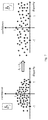
- every dot in the two plots shows the estimated confidence (y-axis) and estimated disparity (x-axis) of a certain 3D point/pixel in the visual scene. Both plots show the dots relative to the same points of the 3D scene. However, the left plot in FIG. 7 shows the case of smaller baselines. If the baselines are larger, then the estimated disparities will be larger in average.
- the confidence value determiner 103 is configured to exclude depth estimates of less reliable pixels on the basis of a filter K defined by the equation:
- K ⁇ ( d ) e - d 2 2 ⁇ ⁇ ⁇ b , where d denotes the disparity of the pixel and b denotes the baseline defined by the reference image and the first subset of the plurality of images.
- FIG. 8 illustrates the approach to apply a post-processing filtering using the filter K of the estimated confidence maps based on their relative estimated disparity values. Only pixels within the bandwidth of the filter are processed using the Gaussian kernel defined by the filter K, i.e. the solid dots shown in FIG. 8 lying below the line 801 .
- the post-processing is performed only for the images along the directions different form the vertical and horizontal one.
- FIG. 9 shows a schematic diagram of an image processing method 900 according to an embodiment.
- the image processing method 900 is configured to determine the depth 107 of a pixel of the reference image 201 of the plurality of images 105 representing a visual scene relative to a plurality of locations, wherein the plurality of locations define a two-dimensional grid 200 with rows and columns and wherein the location of the reference image 201 is associated with a reference row 203 and a reference column 205 of the grid 200 .
- the image processing method 900 comprising the step of determining 901 a first depth estimate on the basis of the reference image 201 and a first subset of the plurality of images 105 for determining the depth 107 of the pixel of the reference image 201 , wherein the images of the first subset are associated with locations being associated with at least one row of the grid different than the reference row 203 and with at least one column of the grid different than the reference column 205 .
- the image processing method 900 can be performed, for instance, by the image processing apparatus 100 .
- Embodiments of the disclosure may be implemented in a computer program for running on a computer system, at least including code portions for performing steps of a method according to the disclosure when run on a programmable apparatus, such as a computer system or enabling a programmable apparatus to perform functions of a device or system according to the disclosure.
- a programmable apparatus such as a computer system or enabling a programmable apparatus to perform functions of a device or system according to the disclosure.
- a computer program is a list of instructions such as a particular application program and/or an operating system.
- the computer program may for instance include one or more of: a subroutine, a function, a procedure, an object method, an object implementation, an executable application, an applet, a servlet, a source code, an object code, a shared library/dynamic load library and/or other sequence of instructions designed for execution on a computer system.
- the computer program may be stored internally on computer readable storage medium or transmitted to the computer system via a computer readable transmission medium. All or some of the computer program may be provided on transitory or non-transitory computer readable media permanently, removably or remotely coupled to an information processing system.
- the computer readable media may include, for example and without limitation, any number of the following: magnetic storage media including disk and tape storage media; optical storage media such as compact disk media (e.g., CD-ROM (Compact Disc, read-only memory), CD-R (Compact Disc, recordable), etc.) and digital video disk storage media; nonvolatile memory storage media including semiconductor-based memory units such as FLASH memory, electrically erasable programmable read-only memory (EEPROM), erasable programmable read-only memory (EPROM), (read-only memory) ROM; ferromagnetic digital memories; magnetoresistive random-access memory (MRAM); volatile storage media including registers, buffers or caches, main memory, random-access memory (RAM), etc.; and data transmission media including computer networks, point-to-point telecommunication equipment, and carrier wave transmission media, just to name a few.
- magnetic storage media including disk and tape storage media
- optical storage media such as compact disk media (e.g., CD-ROM (Compact
- a computer process typically includes an executing (running) program or portion of a program, current program values and state information, and the resources used by the operating system to manage the execution of the process.
- An operating system is the software that manages the sharing of the resources of a computer and provides programmers with an interface used to access those resources.
- An operating system processes system data and user input, and responds by allocating and managing tasks and internal system resources as a service to users and programs of the system.
- the computer system may for instance include at least one processing unit, associated memory and a number of input/output (I/O) devices.
- I/O input/output
- the computer system processes information according to the computer program and produces resultant output information via I/O devices.
- connections as discussed herein may be any type of connection suitable to transfer signals from or to the respective nodes, units or devices, for example via intermediate devices. Accordingly, unless implied or stated otherwise, the connections may for example be direct connections or indirect connections.
- the connections may be illustrated or described in reference to being a single connection, a plurality of connections, unidirectional connections, or bidirectional connections. However, different embodiments may vary the implementation of the connections. For example, separate unidirectional connections may be used rather than bidirectional connections and vice versa.
- plurality of connections may be replaced with a single connection that transfers multiple signals serially or in a time multiplexed manner. Likewise, single connections carrying multiple signals may be separated out into various different connections carrying subsets of these signals. Therefore, many options exist for transferring signals.
- logic blocks are merely illustrative and that alternative embodiments may merge logic blocks or circuit elements or impose an alternate decomposition of functionality upon various logic blocks or circuit elements.
- architectures depicted herein are merely exemplary, and that in fact many other architectures can be implemented which achieve the same functionality.
- any arrangement of components to achieve the same functionality is effectively “associated” such that the desired functionality is achieved.
- any two components herein combined to achieve a particular functionality can be seen as “associated with” each other such that the desired functionality is achieved, irrespective of architectures or intermedial components.
- any two components so associated can also be viewed as being “operably connected,” or “operably coupled,” to each other to achieve the desired functionality.
- the examples, or portions thereof may implemented as soft or code representations of physical circuitry or of logical representations convertible into physical circuitry, such as in a hardware description language of any appropriate type.
- the disclosure is not limited to physical devices or units implemented in nonprogrammable hardware but can also be applied in programmable devices or units able to perform the desired device functions by operating in accordance with suitable program code, such as mainframes, minicomputers, servers, workstations, personal computers, notepads, personal digital assistants, electronic games, automotive and other embedded systems, cell phones and various other wireless devices, commonly denoted in this application as ‘computer systems’.
- suitable program code such as mainframes, minicomputers, servers, workstations, personal computers, notepads, personal digital assistants, electronic games, automotive and other embedded systems, cell phones and various other wireless devices, commonly denoted in this application as ‘computer systems’.
Landscapes
- Engineering & Computer Science (AREA)
- Computer Vision & Pattern Recognition (AREA)
- Physics & Mathematics (AREA)
- General Physics & Mathematics (AREA)
- Theoretical Computer Science (AREA)
- Multimedia (AREA)
- Signal Processing (AREA)
- Image Processing (AREA)
Abstract
Description
- 2D image A two dimensional picture of a real world visual scene acquired, for instance, by a digital camera.
- 4D light field A series of 2D images of a real world visual scene captured on a regular grid (e.g. rectangular or hexagonal) of camera positions.
- Plenoptic camera A camera that captures a 4D light field.
- Depth map Usually a grayscale 2D image of a visual scene where bright pixels indicate points of the scene closer to the camera and darker pixels indicate points further away.
- Reference image One of the images of the 4D light field for which the depth map it to be calculated.
- Confidence map Usually a grayscale 2D image (generally having values between 0 and 1) where bright pixels indicate points of the visual scene whose depth estimation is more reliable and darker pixels indicate pixels corresponding to points of the visual scene whose depth estimation is less reliable.
- Baseline Distance between the centers of 2 consecutive image, i.e. camera, locations.
- Disparity Displacement between the projection of a certain point/pixel of a visual scene in one image and the projection of the corresponding point/pixel in a consecutive neighboring image. The disparity is inversely proportional to the distance of that point/pixel from the camera, i.e. the depth of the point/pixel.
where d denotes the disparity of the pixel and b denotes the baseline defined by the reference image and the first subset of the plurality of images. This implementation form uses only reliable depth estimates for estimating the depth.
where d denotes the disparity of the pixel and b denotes the baseline defined by the reference image and the first subset of the plurality of images.
Claims (17)
Applications Claiming Priority (1)
| Application Number | Priority Date | Filing Date | Title |
|---|---|---|---|
| PCT/EP2015/059232 WO2016173631A1 (en) | 2015-04-28 | 2015-04-28 | An image processing apparatus and method |
Related Parent Applications (1)
| Application Number | Title | Priority Date | Filing Date |
|---|---|---|---|
| PCT/EP2015/059232 Continuation WO2016173631A1 (en) | 2015-04-28 | 2015-04-28 | An image processing apparatus and method |
Publications (2)
| Publication Number | Publication Date |
|---|---|
| US20170316570A1 US20170316570A1 (en) | 2017-11-02 |
| US10692235B2 true US10692235B2 (en) | 2020-06-23 |
Family
ID=53052843
Family Applications (1)
| Application Number | Title | Priority Date | Filing Date |
|---|---|---|---|
| US15/655,841 Active 2035-11-11 US10692235B2 (en) | 2015-04-28 | 2017-07-20 | Image processing apparatus and method for determining a depth of a pixel of a reference image |
Country Status (4)
| Country | Link |
|---|---|
| US (1) | US10692235B2 (en) |
| EP (1) | EP3216006B1 (en) |
| CN (1) | CN107077742B (en) |
| WO (1) | WO2016173631A1 (en) |
Families Citing this family (6)
| Publication number | Priority date | Publication date | Assignee | Title |
|---|---|---|---|---|
| US20180091798A1 (en) * | 2016-09-26 | 2018-03-29 | Imec Taiwan Co. | System and Method for Generating a Depth Map Using Differential Patterns |
| US10271033B2 (en) * | 2016-10-31 | 2019-04-23 | Verizon Patent And Licensing Inc. | Methods and systems for generating depth data by converging independently-captured depth maps |
| EP3687157A4 (en) * | 2017-10-14 | 2020-10-14 | Huawei Technologies Co., Ltd. | Method for capturing images and electronic device |
| EP3598390A1 (en) * | 2018-07-19 | 2020-01-22 | Thomson Licensing | Method for estimating a depth for pixels, corresponding device and computer program product |
| CN111193918B (en) * | 2018-11-14 | 2021-12-28 | 宏达国际电子股份有限公司 | Image processing system and image processing method |
| CN113542721B (en) * | 2020-04-20 | 2023-04-25 | 阿里巴巴集团控股有限公司 | Depth map processing method, video reconstruction method and related devices |
Citations (7)
| Publication number | Priority date | Publication date | Assignee | Title |
|---|---|---|---|---|
| CN101511017A (en) | 2009-03-20 | 2009-08-19 | 西安电子科技大学 | Hierarchical encoder of stereo video space based on grid and decoding method thereof |
| US20110026764A1 (en) * | 2009-07-28 | 2011-02-03 | Sen Wang | Detection of objects using range information |
| US7898569B2 (en) | 2004-07-16 | 2011-03-01 | Vision Robotics Corporation | Angled axis machine vision system and method |
| CN103021013A (en) | 2012-11-28 | 2013-04-03 | 无锡羿飞科技有限公司 | High-efficiency processing method for spherical display and rotary output image of projector |
| DE102012105435A1 (en) | 2012-06-22 | 2013-12-24 | Conti Temic Microelectronic Gmbh | Camera system connected with driver assistance system of vehicle for determining object distance, has main unit to detect partial images for generating image of observed scene in light field area, so as to determine object distance |
| US8619082B1 (en) * | 2012-08-21 | 2013-12-31 | Pelican Imaging Corporation | Systems and methods for parallax detection and correction in images captured using array cameras that contain occlusions using subsets of images to perform depth estimation |
| WO2015028040A1 (en) | 2013-09-02 | 2015-03-05 | Universität Heidelberg | Image processing apparatus, system, method and computer program product for 3d reconstruction |
-
2015
- 2015-04-28 CN CN201580056813.5A patent/CN107077742B/en active Active
- 2015-04-28 EP EP15720681.4A patent/EP3216006B1/en active Active
- 2015-04-28 WO PCT/EP2015/059232 patent/WO2016173631A1/en active Application Filing
-
2017
- 2017-07-20 US US15/655,841 patent/US10692235B2/en active Active
Patent Citations (8)
| Publication number | Priority date | Publication date | Assignee | Title |
|---|---|---|---|---|
| US7898569B2 (en) | 2004-07-16 | 2011-03-01 | Vision Robotics Corporation | Angled axis machine vision system and method |
| CN101511017A (en) | 2009-03-20 | 2009-08-19 | 西安电子科技大学 | Hierarchical encoder of stereo video space based on grid and decoding method thereof |
| US20110026764A1 (en) * | 2009-07-28 | 2011-02-03 | Sen Wang | Detection of objects using range information |
| DE102012105435A1 (en) | 2012-06-22 | 2013-12-24 | Conti Temic Microelectronic Gmbh | Camera system connected with driver assistance system of vehicle for determining object distance, has main unit to detect partial images for generating image of observed scene in light field area, so as to determine object distance |
| US8619082B1 (en) * | 2012-08-21 | 2013-12-31 | Pelican Imaging Corporation | Systems and methods for parallax detection and correction in images captured using array cameras that contain occlusions using subsets of images to perform depth estimation |
| US20150042767A1 (en) * | 2012-08-21 | 2015-02-12 | Pelican Imaging Corporation | Systems and Methods for Measuring Depth Based Upon Occlusion Patterns in Images |
| CN103021013A (en) | 2012-11-28 | 2013-04-03 | 无锡羿飞科技有限公司 | High-efficiency processing method for spherical display and rotary output image of projector |
| WO2015028040A1 (en) | 2013-09-02 | 2015-03-05 | Universität Heidelberg | Image processing apparatus, system, method and computer program product for 3d reconstruction |
Non-Patent Citations (7)
| Title |
|---|
| Choudhury et al., "Multi-epipolar plane image based 3D reconstruction using robust surface fitting," ICVGIP '14, XP055239944, ACM (2014). |
| Diebold et al., "Epipolar Plane Image Refocusing for Improved Depth Estimation and Occlusion Handling," Vision, Modeling, and Visualization, Heidelberg Collaboratory for Image Processing, The Eurographics Association (2013). |
| Kim et al., "Scene Reconstruction from High Spatio-Angular Resolution Light Fields," ACM Transactions on Graphics vol. 32, No. 4, Article 73, ACM (Jul. 2013). |
| MING XIE ; YOULUN XIONG ; CAIHUA XIONG ; HONGHAI LIU ; ZHENCHENG HU: "Intelligent Robotics and Applications", vol. 5928, 16 December 2009, SPRINGER BERLIN HEIDELBERG, Berlin, Heidelberg, ISBN: 978-3-642-10816-7, article LAZAROS NALPANTIDIS ; DIMITRIOS CHRYSOSTOMOU ; ANTONIOS GASTERATOS: "Obtaining Reliable Depth Maps for Robotic Applications from a Quad-Camera System", pages: 906 - 916, XP019135966 |
| Nalpantidis et al., "Obtaining Reliable Depth Maps for Robotic Applications from a Quad-Camera System," ICIRA 2009, pp. 906-916, XP019135966, Springer-Verlag Berlin Heidelberg, (2009). |
| Wanner et al., "Globally Consistent Depth Labeling of 4D Light Fields," 2012 IEEE Conference on Computer Vision and Pattern Recognition (CVPR), pp. 41-48, Institute of Electrical and Electronics Engineers, New York, New York (2012). |
| Wanner et al., "Orientation Analysis in 4D Light Fields," PhD Thesis, Heidelberg Collaboratory for Image Processing (HCI), University of Heidelberg, (2014). |
Also Published As
| Publication number | Publication date |
|---|---|
| EP3216006B1 (en) | 2020-06-10 |
| US20170316570A1 (en) | 2017-11-02 |
| CN107077742B (en) | 2020-06-26 |
| CN107077742A (en) | 2017-08-18 |
| EP3216006A1 (en) | 2017-09-13 |
| WO2016173631A1 (en) | 2016-11-03 |
Similar Documents
| Publication | Publication Date | Title |
|---|---|---|
| US10692235B2 (en) | Image processing apparatus and method for determining a depth of a pixel of a reference image | |
| US10818026B2 (en) | Systems and methods for hybrid depth regularization | |
| Lu et al. | Depth enhancement via low-rank matrix completion | |
| US9497437B2 (en) | Digital refocusing method | |
| JP5178875B2 (en) | Image processing method for corresponding point search | |
| Hua et al. | Holopix50k: A large-scale in-the-wild stereo image dataset | |
| US9240048B2 (en) | Depth estimation using three-dimensional epipolar data structures | |
| JP2018534698A (en) | Method and system for large scale determination of RGBD camera attitude | |
| US9406140B2 (en) | Method and apparatus for generating depth information | |
| KR20130112311A (en) | Apparatus and method for reconstructing dense three dimension image | |
| Lo et al. | Joint trilateral filtering for depth map super-resolution | |
| CN112750133A (en) | Computer vision training system and method for training a computer vision system | |
| CN109661815B (en) | Robust disparity estimation in the presence of significant intensity variations of the camera array | |
| Li et al. | Epi-based oriented relation networks for light field depth estimation | |
| US20160247284A1 (en) | Image processor with multi-channel interface between preprocessing layer and one or more higher layers | |
| CN108234826B (en) | Image processing method and device | |
| US11153479B2 (en) | Image processing apparatus, capable of detecting an amount of motion between images by tracking a point across one or more images, image capturing apparatus, image processing method, and storage medium | |
| Suzuki et al. | Disparity estimation from light fields using sheared EPI analysis | |
| WO2016058359A1 (en) | Method and device for generating three-dimensional image | |
| CN116092035A (en) | Lane line detection method, lane line detection device, computer equipment and storage medium | |
| EP4064193A1 (en) | Real-time omnidirectional stereo matching using multi-view fisheye lenses | |
| Tran et al. | Variational disparity estimation framework for plenoptic images | |
| CN116051736A (en) | Three-dimensional reconstruction method, device, edge equipment and storage medium | |
| de Oliveira et al. | On the performance of DIBR methods when using depth maps from state-of-the-art stereo matching algorithms | |
| EP2860975A1 (en) | Method for processing at least one disparity map, corresponding electronic device and computer program product |
Legal Events
| Date | Code | Title | Description |
|---|---|---|---|
| AS | Assignment |
Owner name: HUAWEI TECHNOLOGIES CO., LTD., CHINA Free format text: ASSIGNMENT OF ASSIGNORS INTEREST;ASSIGNORS:PAPADHIMITRI, THOMA;URFALIOGLU, ONAY;NAVARRO FRUCTUOSO, HECTOR;AND OTHERS;SIGNING DATES FROM 20170626 TO 20170703;REEL/FRAME:043059/0326 |
|
| AS | Assignment |
Owner name: HUAWEI TECHNOLOGIES CO., LTD., CHINA Free format text: ASSIGNMENT OF ASSIGNORS INTEREST;ASSIGNORS:PAPADHIMITRI, THOMA;URFALIOGLU, ONAY;FRUCTUOSO, HECTOR NAVARRO;AND OTHERS;SIGNING DATES FROM 20170626 TO 20170703;REEL/FRAME:043216/0015 |
|
| STPP | Information on status: patent application and granting procedure in general |
Free format text: DOCKETED NEW CASE - READY FOR EXAMINATION |
|
| STPP | Information on status: patent application and granting procedure in general |
Free format text: NON FINAL ACTION MAILED |
|
| STPP | Information on status: patent application and granting procedure in general |
Free format text: RESPONSE TO NON-FINAL OFFICE ACTION ENTERED AND FORWARDED TO EXAMINER |
|
| STPP | Information on status: patent application and granting procedure in general |
Free format text: FINAL REJECTION MAILED |
|
| STPP | Information on status: patent application and granting procedure in general |
Free format text: ADVISORY ACTION MAILED |
|
| STPP | Information on status: patent application and granting procedure in general |
Free format text: RESPONSE AFTER FINAL ACTION FORWARDED TO EXAMINER |
|
| STPP | Information on status: patent application and granting procedure in general |
Free format text: NOTICE OF ALLOWANCE MAILED -- APPLICATION RECEIVED IN OFFICE OF PUBLICATIONS |
|
| STPP | Information on status: patent application and granting procedure in general |
Free format text: NOTICE OF ALLOWANCE MAILED -- APPLICATION RECEIVED IN OFFICE OF PUBLICATIONS |
|
| STPP | Information on status: patent application and granting procedure in general |
Free format text: PUBLICATIONS -- ISSUE FEE PAYMENT VERIFIED |
|
| STCF | Information on status: patent grant |
Free format text: PATENTED CASE |
|
| MAFP | Maintenance fee payment |
Free format text: PAYMENT OF MAINTENANCE FEE, 4TH YEAR, LARGE ENTITY (ORIGINAL EVENT CODE: M1551); ENTITY STATUS OF PATENT OWNER: LARGE ENTITY Year of fee payment: 4 |