US10691293B2 - Display device and computer-readable non-transitory recording medium with display control program stored thereon - Google Patents
Display device and computer-readable non-transitory recording medium with display control program stored thereon Download PDFInfo
- Publication number
- US10691293B2 US10691293B2 US15/987,170 US201815987170A US10691293B2 US 10691293 B2 US10691293 B2 US 10691293B2 US 201815987170 A US201815987170 A US 201815987170A US 10691293 B2 US10691293 B2 US 10691293B2
- Authority
- US
- United States
- Prior art keywords
- icon
- display
- display screen
- explanatory
- display control
- Prior art date
- Legal status (The legal status is an assumption and is not a legal conclusion. Google has not performed a legal analysis and makes no representation as to the accuracy of the status listed.)
- Active
Links
- 230000008859 change Effects 0.000 claims description 33
- 230000002596 correlated effect Effects 0.000 claims description 29
- 238000000034 method Methods 0.000 claims description 24
- 230000008569 process Effects 0.000 claims description 24
- 230000000875 corresponding effect Effects 0.000 claims description 5
- 230000006870 function Effects 0.000 description 59
- 238000010586 diagram Methods 0.000 description 11
- 238000010079 rubber tapping Methods 0.000 description 9
- 230000009471 action Effects 0.000 description 2
- 238000012545 processing Methods 0.000 description 2
- 238000013459 approach Methods 0.000 description 1
- 230000006835 compression Effects 0.000 description 1
- 238000007906 compression Methods 0.000 description 1
- 239000011521 glass Substances 0.000 description 1
- 238000010348 incorporation Methods 0.000 description 1
- 238000012986 modification Methods 0.000 description 1
- 230000004048 modification Effects 0.000 description 1
- 230000004044 response Effects 0.000 description 1
- 238000002834 transmittance Methods 0.000 description 1
Images


Classifications
-
- G—PHYSICS
- G06—COMPUTING; CALCULATING OR COUNTING
- G06F—ELECTRIC DIGITAL DATA PROCESSING
- G06F3/00—Input arrangements for transferring data to be processed into a form capable of being handled by the computer; Output arrangements for transferring data from processing unit to output unit, e.g. interface arrangements
- G06F3/01—Input arrangements or combined input and output arrangements for interaction between user and computer
- G06F3/048—Interaction techniques based on graphical user interfaces [GUI]
- G06F3/0481—Interaction techniques based on graphical user interfaces [GUI] based on specific properties of the displayed interaction object or a metaphor-based environment, e.g. interaction with desktop elements like windows or icons, or assisted by a cursor's changing behaviour or appearance
- G06F3/04817—Interaction techniques based on graphical user interfaces [GUI] based on specific properties of the displayed interaction object or a metaphor-based environment, e.g. interaction with desktop elements like windows or icons, or assisted by a cursor's changing behaviour or appearance using icons
-
- G—PHYSICS
- G06—COMPUTING; CALCULATING OR COUNTING
- G06F—ELECTRIC DIGITAL DATA PROCESSING
- G06F9/00—Arrangements for program control, e.g. control units
- G06F9/06—Arrangements for program control, e.g. control units using stored programs, i.e. using an internal store of processing equipment to receive or retain programs
- G06F9/44—Arrangements for executing specific programs
- G06F9/451—Execution arrangements for user interfaces
- G06F9/453—Help systems
-
- G—PHYSICS
- G06—COMPUTING; CALCULATING OR COUNTING
- G06F—ELECTRIC DIGITAL DATA PROCESSING
- G06F3/00—Input arrangements for transferring data to be processed into a form capable of being handled by the computer; Output arrangements for transferring data from processing unit to output unit, e.g. interface arrangements
- G06F3/01—Input arrangements or combined input and output arrangements for interaction between user and computer
- G06F3/03—Arrangements for converting the position or the displacement of a member into a coded form
- G06F3/041—Digitisers, e.g. for touch screens or touch pads, characterised by the transducing means
- G06F3/0416—Control or interface arrangements specially adapted for digitisers
-
- G—PHYSICS
- G06—COMPUTING; CALCULATING OR COUNTING
- G06F—ELECTRIC DIGITAL DATA PROCESSING
- G06F3/00—Input arrangements for transferring data to be processed into a form capable of being handled by the computer; Output arrangements for transferring data from processing unit to output unit, e.g. interface arrangements
- G06F3/01—Input arrangements or combined input and output arrangements for interaction between user and computer
- G06F3/048—Interaction techniques based on graphical user interfaces [GUI]
- G06F3/0481—Interaction techniques based on graphical user interfaces [GUI] based on specific properties of the displayed interaction object or a metaphor-based environment, e.g. interaction with desktop elements like windows or icons, or assisted by a cursor's changing behaviour or appearance
- G06F3/0482—Interaction with lists of selectable items, e.g. menus
-
- G—PHYSICS
- G06—COMPUTING; CALCULATING OR COUNTING
- G06F—ELECTRIC DIGITAL DATA PROCESSING
- G06F3/00—Input arrangements for transferring data to be processed into a form capable of being handled by the computer; Output arrangements for transferring data from processing unit to output unit, e.g. interface arrangements
- G06F3/01—Input arrangements or combined input and output arrangements for interaction between user and computer
- G06F3/048—Interaction techniques based on graphical user interfaces [GUI]
- G06F3/0487—Interaction techniques based on graphical user interfaces [GUI] using specific features provided by the input device, e.g. functions controlled by the rotation of a mouse with dual sensing arrangements, or of the nature of the input device, e.g. tap gestures based on pressure sensed by a digitiser
- G06F3/0488—Interaction techniques based on graphical user interfaces [GUI] using specific features provided by the input device, e.g. functions controlled by the rotation of a mouse with dual sensing arrangements, or of the nature of the input device, e.g. tap gestures based on pressure sensed by a digitiser using a touch-screen or digitiser, e.g. input of commands through traced gestures
- G06F3/04883—Interaction techniques based on graphical user interfaces [GUI] using specific features provided by the input device, e.g. functions controlled by the rotation of a mouse with dual sensing arrangements, or of the nature of the input device, e.g. tap gestures based on pressure sensed by a digitiser using a touch-screen or digitiser, e.g. input of commands through traced gestures for inputting data by handwriting, e.g. gesture or text
-
- H—ELECTRICITY
- H04—ELECTRIC COMMUNICATION TECHNIQUE
- H04N—PICTORIAL COMMUNICATION, e.g. TELEVISION
- H04N1/00—Scanning, transmission or reproduction of documents or the like, e.g. facsimile transmission; Details thereof
- H04N1/0035—User-machine interface; Control console
- H04N1/00352—Input means
- H04N1/00392—Other manual input means, e.g. digitisers or writing tablets
-
- H—ELECTRICITY
- H04—ELECTRIC COMMUNICATION TECHNIQUE
- H04N—PICTORIAL COMMUNICATION, e.g. TELEVISION
- H04N1/00—Scanning, transmission or reproduction of documents or the like, e.g. facsimile transmission; Details thereof
- H04N1/0035—User-machine interface; Control console
- H04N1/00405—Output means
- H04N1/00474—Output means outputting a plurality of functional options, e.g. scan, copy or print
Definitions
- the present disclosure relates to a display device and a computer-readable non-transitory recording medium with a display control program stored thereon and, particularly, to a technology for displaying icons on a display screen of a display section.
- an object e.g., a user's finger
- a display screen on which an operation image having icons arranged therein is displayed is detected, displaying an explanatory note describing a function of one of the icons displayed near a position in proximity to the object by superposing the explanatory note on the operation image. Accordingly, the user can recognize the function of the icon.
- a display device includes a display section and a control unit.
- the display section has a touch panel function of sensing proximity and contact of an object to and with a display screen.
- the control unit includes a processor and, by executing a control program through the processor, acts as a display control section, an operation receiving section, and a controller.
- the display control section displays on the display screen an operation image in which a plurality of icons are arranged.
- the operation receiving section receives an operation from a user through the touch panel function. When the operation receiving section receives a user operation of instructing execution of a function correlated to one icon of the plurality of icons, the controller executes the function.
- the display control section displays an explanatory image including the one icon and a description of the function correlated to the one icon in a whole area of the display.
- the display control program causes a computer including a processor to act, when the processor executes the display control program, as a display control section, an operation receiving section and a controller.
- the display control section displays an operation image in which a plurality of icons are arranged on a display screen of a display section having a touch panel function of sensing proximity and contact of an object.
- the operation receiving section receives an operation from a user through the touch panel function.
- the controller executes the function.
- the display control program further causes the computer to act so that, after the operation receiving section receives a user operation of putting an object close to one icon of the plurality of icons displayed on the display screen, when a state in which the object is being close to the one icon continues for a predetermined time, the display control section displays an explanatory image including the one icon and a description of the function correlated to the one icon in a whole area of the display.
- FIG. 2A and FIG. 2B are diagrams illustrating an example of an operation image displayed on a display screen of a display section.
- FIG. 3 is a diagram illustrating an example of change of images displayed on the display screen of the display section.
- FIG. 4 is an explanatory diagram for describing an order assigned to each icon.
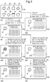
- FIG. 5 is a diagram illustrating an example of change of images displayed on the display screen of the display section.
- FIG. 6 is a flowchart illustrating an example of a process performed by a control unit in the image forming device as the display device according to the first embodiment.
- FIG. 7 is a flowchart illustrating an example of a process performed by the control unit in the image forming device as the display device according to the first embodiment.
- FIG. 8 is a diagram illustrating an example of change of images displayed on the display screen of the display section.
- FIG. 9 is a diagram illustrating an example of change of images displayed on the display screen of the display section.
- FIG. 1 is a functional block diagram schematically illustrating major internal components of an image forming device as a display device according to the first embodiment of the present disclosure.
- the display device is, for example, an image forming device 1 .
- the image forming device 1 has a plurality of functions such as a copy function, a printer function, a scanner function and a facsimile function.
- the image forming device 1 includes a control unit 10 , a document feeding unit 6 , a document reading unit 5 , an image forming unit 12 , a fixing unit 13 , a paper feeding unit 14 , an HDD 92 and an operation unit 47 .
- a case in which a document reading operation is performed in the image forming device 1 will be described.
- An image of a document transferred through the document feeding unit 6 or a document mounted on a platen glass is optically read by the document reading unit 5 and thus image data is generated.
- the image data generated by the document reading unit 5 is stored in an image memory that is not shown, and the like.
- the image forming unit 12 forms an image on recording paper serving as a recording medium and being fed from the paper feeding unit 14 on the basis of image data generated through the document reading operation, image data received from a computer as an external device connected through a network, or the like.
- the fixing unit 13 fixes a toner image onto the recording paper through thermal compression, and the recording paper on which the fixing process has been performed is ejected to an ejection tray.
- the paper feeding unit 14 includes a paper feeding cassette.
- the operation unit 47 receives instructions such as an image forming operation execution instruction from an operator with respect to various operations and processes that can be executed by the image forming device 1 .
- the operation unit 47 includes a display section 473 that displays an operation guidance and the like to the operator.
- the display section 473 has a touch panel function that senses proximity and contact of an object (e.g., a user's finger) to and with a display screen and, when the user's finger approaches or comes in contact with the display screen, transmits a signal indicating the proximity position or the contact position to the control unit 10 .
- a display control section 101 (which will be described later) changes display screens of the display section 473 on the basis of the signal. Accordingly, the operator can operate the image forming device 1 by putting a finger close to an icon, a button or a key displayed on the screen or touching the same with the finger.
- the control unit 10 serves as the controller 100 , the display control section 101 and the operation receiving section 102 through operations according to a display control program and the like according to an embodiment of the present disclosure, which is stored in the HDD 92 .
- the controller 100 and the like may be respectively configured using hardware circuits instead of operations according to the display control program and the like, performed by the control unit 10 . This similarly applies to each embodiment hereinafter unless particularly mentioned.
- the controller 100 controls the overall operation of the image forming device 1 .
- the controller 100 is connected to the document feeding unit 6 , the document reading unit 5 , the image forming unit 12 , the fixing unit 13 , the paper feeding unit 14 and the operation unit 47 and controls driving of these components.
- the display control section 101 controls display of the display section 473 .
- the display control section 101 reads an image showing icons (simply referred to as icons hereinafter) stored in the HDD 92 and displays a read operation image (for example, an operation image DA 1 shown in FIG. 2A and an operation image DA 2 shown in FIG. 2B ) in which a plurality of icons are arranged on a display screen 4730 of the display section 473 .
- FIG. 2A and FIG. 2B are diagrams illustrating examples of the operation image displayed on the display screen 4730 of the display section 473 .
- a plurality of icons A 1 to A 8 are arranged in the operation image DA 1 shown in FIG. 2A and a plurality of different icons A 9 to A 16 are arranged in the operation image DA 2 shown in FIG. 2B .
- the operation receiving section 102 receives a user operation input by a user to the operation unit 47 .
- the display section 473 serving as the operation unit 47 includes the touch panel function, as described above, and proximity or contact of the user to or with the display screen 4730 of the display section 473 are input as a user operation through the touch panel function.
- the operation receiving section 102 receives the user operation.
- the operation receiving section 102 receives, as a user operation, a gesture operation, such as putting a finger close to the display screen 4730 , sliding of a finger in the air in a state in which the finger is close to the display screen 4730 , an action of tapping the display screen 4730 with a finger once (tapping operation) or an action of quickly flicking the display screen 4730 with a finger (flicking operation).
- a gesture operation such as putting a finger close to the display screen 4730 , sliding of a finger in the air in a state in which the finger is close to the display screen 4730 , an action of tapping the display screen 4730 with a finger once (tapping operation) or an action of quickly flicking the display screen 4730 with a finger (flicking operation).
- the display control section 101 reads text data of an explanatory note that describes the function of the icon, which is stored in the HDD 92 , and displays an explanatory image showing the icon and the explanatory note describing the function of the icon (an image describing the function of the icon, for example, explanatory images DB 1 and DB 2 shown in FIG. 3 ) in the whole area of the display screen 4730 .
- FIG. 3 is a diagram illustrating an example of change of images displayed on the display screen 4730 of the display section 473 .
- the plurality of icons A 1 to A 8 are arranged in the operation image DA 1 displayed on the upper left of FIG. 3 .
- the explanatory image DB 1 including the icon A 1 and an explanatory note E 1 describing the function of the icon A 1 is displayed in the whole area of the display screen 4730 by the display control section 101 .
- the explanatory image DB 2 including the icon A 3 and an explanatory note E 3 describing the function of the icon A 3 is displayed in the whole area of the display screen 4730 by the display control section 101 .
- the operation receiving section 102 receives a user operation of instructing a display change to an explanatory image including an icon different from an icon, which is included in an explanatory image (e.g., explanatory image DB 1 ) displayed on the display screen 4730 , and an explanatory note describing the function of the different icon.
- an operation of sliding an object in the air in a state in which the object (e.g., a user's finger) is close to the explanatory image displayed on the display screen of the display section 473 may be conceived.
- the display control section 101 When the operation receiving section 102 receives this user operation, the display control section 101 performs display change to sequentially change explanatory image displays. Specifically, an order is assigned to each icon in advance, and the display control section 101 reads an icon preceding or following, in order, an icon included in an explanatory image displayed on the display screen 4730 at this time and text data of an explanatory note describing the function of the icon from the HDD 92 in response to the direction of sliding received by the operation receiving section 102 and displays an explanatory image including the icon and the explanatory note describing the function of the icon in the whole area of the display screen 4730 . In this manner, the display control section 101 sequentially changes and displays explanatory images for all icons stored in the image forming device 1 in a cyclical manner.
- an explanatory image DB 3 including the icon A 14 following the icon A 1 in order and an explanatory note E 14 describing the function of the icon A 14 is displayed in the whole area of the display screen 4730 by the display control section 101 .
- an explanatory image DB 4 including the icon A 10 following the icon A 14 in order and an explanatory note E 11 ) describing the function of the icon A 10 is displayed in the whole area of the display screen 4730 by the display control section 101 .
- an explanatory image DB 5 including the icon A 12 preceding the icon A 1 in order and an explanatory note E 12 describing the function of the icon A 12 is displayed in the whole area of the display screen 4730 by the display control section 101 .
- the explanatory image DB 1 including the icon A 1 following the icon A 12 in order and an explanatory note E 1 describing the function of the icon A 1 is displayed again in the whole area of the display screen 4730 by the display control section 101 .
- the operation receiving section 102 When the operation receiving section 102 receives a first operation (e.g., long press) predetermined for an icon (e.g., icon A 14 ) included in an explanatory image in a state in which an explanatory image (e.g., explanatory image DB 3 ) is displayed on the display screen 4730 , the controller 100 reads a program correlated to the icon and stored in the HDD 92 and executes the function of the icon.
- a first operation e.g., long press
- the display control section 101 changes the display of the display screen 4730 to the operation image (e.g., the operation image DA 2 shown in FIG. 2 ) in which the icon is disposed and displays an image showing the change process through an animation.
- the controller 100 reads a program correlated to the icon and stored in the HDD 92 and executes the function of the icon.
- FIG. 5 is a diagram illustrating an example of change of images displayed on the display screen 4730 of the display section 473 .
- the controller 100 immediately executes the function of the icon A 14 .
- the operation image DA 2 in which the icon A 14 is disposed is displayed in the display screen 4730 by the display control section 101 , and then the function of the icon A 14 is executed by the controller 100 .
- the display control section 101 does not instantaneously perform an image change to the operation image DA 2 and displays the operation image DA 1 on the display screen 4730 first and then displays an image showing the change process through an animation.
- the display control section 101 acquires coordinates indicating the position close to the object from operation information provided from the operation unit 47 (S 2 ) and determines whether an icon is disposed at the position close to the object on the basis of the acquired coordinates (S 3 ).
- the display control section 101 determines whether an icon is disposed at the position close to the object (YES in S 3 ).
- the display control section 101 determines whether the state in which the object is close to the position has continued for the predetermined time T 1 from the time at which the operation receiving section 102 registered the proximity of the object to the display screen 4730 (S 4 ).
- the process returns to S 1 .
- the display control section 101 determines that the state in which the object is close to the position has continued for the predetermined time T 1 (YES in S 4 )
- the display control section 101 reads text data of an explanatory note describing the function of the corresponding icon, stored in the HDD 92 (S 5 ), stores the content displayed on the display screen 4730 at this time in the HDD 92 (S 6 ), and then displays an explanatory image (e.g., the explanatory image DB 1 shown in FIG. 3 ) including the icon and the explanatory note describing the function of the icon in the whole area of the display screen 4730 (S 7 ). Thereafter, the process proceeds to S 21 ( FIG. 7 ).
- the process returns to S 1 . That is, when the operation receiving section 102 has not registered proximity of the object to the display screen 4730 until the predetermined time T 1 elapses (i.e., when the object is separated from the display screen 4730 or the object comes in contact with the display screen 4730 ), the process returns to S 1 instead of proceeding to S 5 .
- the display control section 101 determines whether the operation receiving section 102 has not registered proximity of the object to the display screen 4730 (NO in S 1 ) in S 1 , the display control section 101 determines whether the operation receiving section 102 has received a user operation of touching the display screen 4730 with the object (S 8 ).
- the display control section 101 determines that the operation receiving section 102 has received the user operation of touching the display screen 4730 with the object (YES in S 8 ), the display control section 101 acquires coordinates indicating the position touched by the object on the basis of operation information transmitted from the operation unit 47 (S 9 ) and determines whether an icon is disposed at the position touched by the object on the basis of the acquired coordinates (S 10 ).
- the controller 100 When the display control section 101 determines that an icon is disposed at the position touched by the object (YES in S 10 ), the controller 100 reads a program correlated to the icon stored in the HDD 92 and executes the function of the icon (S 11 ). Thereafter, the process ends. On the other hand, when the display control section 101 determines that no icon is disposed at the position touched by the object (NO in S 10 ), the process returns to S 1 .
- the display control section 101 determines whether the operation receiving section 102 has registered proximity of the object to the display screen 4730 (S 21 ) and, when it is determined that the operation receiving section 102 has registered proximity of the object to the display screen 4730 (YES in S 21 ), acquires coordinates indicating the position close to the object from operation information provided from the operation unit 47 (S 22 ).
- the display control section 101 determines whether the object has been slid in any of leftward and rightward directions in the air on the basis of the acquired coordinates (also including the last acquired coordinates) (S 23 ). For example, when the coordinates (the coordinates indicating the position close to the object) have changed by a predetermined magnitude or more in any of the leftward and rightward directions, the display control section 101 may determine that the object has been slid in the air.
- the display control section 101 determines whether the direction in which the object has been slid is any of the leftward and rightward directions (S 24 ).
- the display control section 101 reads text data of an explanatory note describing the function of an icon following, in order, an icon included in an explanatory image displayed on the display screen 4730 at this time from the HDD 92 (S 25 ) and displays an explanatory image (e.g., the explanatory image DB 3 shown in FIG. 3 ) including the icon and the explanatory note describing the function of the icon in the whole area of the display screen 4730 (S 26 ). Thereafter, the process returns to S 21 .
- the display control section 101 determines that the object has been slid in the rightward direction (i.e., reverse to the forward direction when the leftward direction is regarded as the forward direction) (to the right in S 24 )
- the display control section 101 reads text data of an explanatory note describing the function of an icon preceding, in order, the icon included in the explanatory image displayed on the display screen 4730 from the HDD 92 (S 27 ) and displays an explanatory image (e.g., the explanatory image DB 5 shown in FIG. 3 ) including the icon and the explanatory note describing the function of the icon in the whole area of the display screen 4730 (S 26 ). Thereafter, the process returns to S 21 .
- an explanatory image e.g., the explanatory image DB 5 shown in FIG. 3
- the display control section 101 determines whether the operation receiving section 102 has received a user operation of touching the display screen 4730 with the object (S 28 ).
- the display control section 101 determines that the operation receiving section 102 has received the user operation of touching the display screen 4730 with the object (YES in S 28 ), the display control section 101 acquires coordinates indicating the position touched by the object (S 29 ) on the basis of operation information transmitted from the operation unit 47 and determines whether an icon is disposed at the position touched by the object on the basis of the acquired coordinates (S 30 ).
- the controller 100 determines whether the user operation received by the operation receiving section 102 is any one of a predetermined first operation (e.g., a long press) and a predetermined second operation (e.g., tapping operation) (S 31 ).
- a predetermined first operation e.g., a long press
- a predetermined second operation e.g., tapping operation
- the controller 100 determines that the user operation received by the operation receiving section 102 is the predetermined first operation (the long press in S 31 )
- the controller 100 reads a program correlated to the icon stored in the HDD 92 and executes the function of the icon (S 32 ). Thereafter, the process ends.
- the display control section 101 changes the display of the display screen 4730 to the operation image (e.g., the operation image DA 2 shown in FIG. 5 ) in which the corresponding icon is disposed and further displays an image showing the change process through an animation, as shown at the right of FIG. 5 (S 33 ).
- the controller 100 reads a program correlated to the corresponding icon and stored in the HDD 92 and executes the function of the icon (S 32 ). Thereafter, the process ends.
- the display control section 101 determines that the operation receiving section 102 has not received the user operation of touching the display screen 4730 with the object in S 28 (NO in S 28 ), the object is removed from the display screen 4730 , and thus the display control section 101 returns the display of the display screen 4730 to the state before display change, which is stored in S 7 ( FIG. 6 ) (S 34 ). Thereafter, the process returns to S 1 ( FIG. 6 ).
- an explanatory image including an explanatory note describing the function of an icon is displayed in the whole area of the display screen 4730 , and thus the area in which the explanatory note is displayed is relatively wide. Accordingly, it is possible to realize detailed description of the function of an icon without a complicated display on the display screen 4730 .
- the display device may feel troublesome when a display change to an explanatory image is performed whenever an object (e.g., a user's finger) is put close to an icon
- the above-described display change is performed not only when the object is put close to the icon but also when the state in which the object is close to the icon continues for the predetermined time T 1 , and thus the user can avoid feeling troublesome due to the display change.
- the technology disclosed in the background displays an explanatory note for describing the function of an icon
- the explanatory note is displayed by overlapping with a part of an operation image and thus an area in which the explanatory note is displayed is relatively narrow. Accordingly, it is difficult to describe the function of the icon in detail.
- the function of an icon associated with a plurality of options requires a large amount of description, and thus it is difficult to describe the function in a narrow area. Even if the function can be described, a display on the display screen of the display section may become complicated.
- the present embodiment can realize a display of appropriate description of the function of an icon while preventing the display on the display screen of the display section from becoming complicated.
- explanatory images with respect to all icons can be sequentially changed in a cyclical manner and thus the user can recognize the function of a target icon without displaying the operation image in which the target icon is disposed on the display screen 4730 . Accordingly, operation efficiency can be improved.
- the function of an icon having an explanatory image is executed when the user touches (e.g., long-presses or taps) the icon. That is, it is possible to execute the function of a target icon by operating an explanatory image without displaying an operation image in which the target icon is disposed on the display screen 4730 , and thus usability is considerably improved.
- the operation image in which the target icon is disposed is displayed first on the display screen 4730 through an animation and then the function of the target icon is executed, and thus the user can correctly recognize the place where the target icon is disposed. Accordingly, the efficiency of the following operations can be improved.
- the display control section 101 may read an icon that is a target to be changed to in each of the forward direction and the reverse direction and the name of the icon from the HDD 92 in the order assigned to each icon and display an explanatory image including the icon that is the target to be changed to and the name of the icon on the display screen 4730 before being changed.
- the icon A 14 following the icon A 1 in order which is a target to be changed to when sliding in the forward direction is performed, and the name N 14 thereof are displayed at the right edge of the explanatory image DB 11
- the icon A 12 preceding the icon A 1 in order and the name N 12 thereof are displayed at the left edge of the explanatory image DB 11 by the display control section 101 .
- the icon A 10 and the name N 10 thereof, the icon A 11 and the name N 11 thereof, and the icon A 1 and the name N 1 thereof are respectively displayed at the right edges of explanatory images DB 13 , DB 14 and DB 15
- the icon A 1 and the name N 1 thereof, the icon A 14 and the name N 14 thereof, and the icon A 7 and the name N 7 thereof are respectively displayed at the left edges of explanatory images DB 13 , DB 14 and DB 15 by the display control section 101 .
- the display control section 101 may transparently display an operation image (e.g., the operation image DA 1 shown in FIG. 3 ), which has been displayed on the display screen 4730 at the time, such that the user views the explanatory image through the operation image, to thereby simultaneously display the operation image and the explanatory image on the display screen 4730 .
- the operation image it is desirable that the operation image have high transparency (transmittance) such that the display on the display screen 4730 does not become complicated.
- the user operation may be an operation of moving the object while the object is in contact with the explanatory image (e.g., an operation of flicking the object to the left or right) in a second embodiment.
- the display control section 101 may display the explanatory image DB 3 ( FIG. 3 ).
- the display control section 101 may display the explanatory image DB 5 ( FIG. 3 ).
- the operation receiving section 102 receives an operation performed on a first instruction button B 1 (a right arrow shown in FIG. 9 ) or a second instruction button B 2 (a left arrow shown in FIG. 9 ) displayed by the display control section 101 as the user operation.
- the display control section 101 displays an explanatory image (e.g., an explanatory image DB 21 ) including the first instruction button B 1 that instructs a display change of the explanatory images in the forward direction and the second instruction button B 2 that instructs a display change of explanatory images in the direction reverse to the forward direction on the display screen 4730 , as shown in FIG. 9 .
- the display control section 101 displays an explanatory image DB 23 .
- the display control section 101 displays an explanatory image DB 24 .
- the display control section 101 displays an explanatory image DB 25 .
- the display control section 101 displays the explanatory image DB 21 .
- the present disclosure is not limited to the configuration of the above-described embodiments and may be modified in various manners.
- an embodiment of the display device according to the present disclosure is described using an image forming device in the above embodiments, this is merely an example and the display device according to the present disclosure may be a mobile device such as a smartphone including a display section or other electronic apparatuses.
Abstract
Description
Claims (9)
Applications Claiming Priority (2)
| Application Number | Priority Date | Filing Date | Title |
|---|---|---|---|
| JP2017110876A JP6737239B2 (en) | 2017-06-05 | 2017-06-05 | Display device and display control program |
| JP2017-110876 | 2017-06-05 |
Publications (2)
| Publication Number | Publication Date |
|---|---|
| US20180348994A1 US20180348994A1 (en) | 2018-12-06 |
| US10691293B2 true US10691293B2 (en) | 2020-06-23 |
Family
ID=64458793
Family Applications (1)
| Application Number | Title | Priority Date | Filing Date |
|---|---|---|---|
| US15/987,170 Active US10691293B2 (en) | 2017-06-05 | 2018-05-23 | Display device and computer-readable non-transitory recording medium with display control program stored thereon |
Country Status (2)
| Country | Link |
|---|---|
| US (1) | US10691293B2 (en) |
| JP (1) | JP6737239B2 (en) |
Families Citing this family (2)
| Publication number | Priority date | Publication date | Assignee | Title |
|---|---|---|---|---|
| CN111104012B (en) * | 2019-12-12 | 2021-06-15 | 惠州Tcl移动通信有限公司 | Distance measuring method and device, storage medium and terminal equipment |
| CN111596810B (en) * | 2020-06-24 | 2021-10-12 | 腾讯科技(深圳)有限公司 | Scribble identification method, device, equipment and storage medium |
Citations (5)
| Publication number | Priority date | Publication date | Assignee | Title |
|---|---|---|---|---|
| US20050071761A1 (en) * | 2003-09-25 | 2005-03-31 | Nokia Corporation | User interface on a portable electronic device |
| US7783983B1 (en) * | 2006-04-13 | 2010-08-24 | Emc Corporation | User interface for controls |
| JP2012133523A (en) | 2010-12-21 | 2012-07-12 | Sony Corp | Display control device, display control method and program |
| US20140380249A1 (en) * | 2013-06-25 | 2014-12-25 | Apple Inc. | Visual recognition of gestures |
| US20150067594A1 (en) * | 2013-09-03 | 2015-03-05 | Samsung Electronics Co., Ltd. | Electronic device and method for controlling screen |
Family Cites Families (5)
| Publication number | Priority date | Publication date | Assignee | Title |
|---|---|---|---|---|
| JP2007065809A (en) * | 2005-08-30 | 2007-03-15 | Sony Corp | Help guidance display method, help guidance display device, information processor, print kiosk device and program |
| CN103874976B (en) * | 2012-02-14 | 2018-05-18 | 松下电器产业株式会社 | Electronic equipment |
| EP2818984B1 (en) * | 2012-02-20 | 2017-10-25 | NEC Corporation | Touch panel input device and control method for same |
| US8910063B2 (en) * | 2012-03-27 | 2014-12-09 | Cisco Technology, Inc. | Assisted display for command line interfaces |
| JP2016009420A (en) * | 2014-06-26 | 2016-01-18 | 株式会社沖データ | Information processing apparatus and information processing method |
-
2017
- 2017-06-05 JP JP2017110876A patent/JP6737239B2/en not_active Expired - Fee Related
-
2018
- 2018-05-23 US US15/987,170 patent/US10691293B2/en active Active
Patent Citations (6)
| Publication number | Priority date | Publication date | Assignee | Title |
|---|---|---|---|---|
| US20050071761A1 (en) * | 2003-09-25 | 2005-03-31 | Nokia Corporation | User interface on a portable electronic device |
| US7783983B1 (en) * | 2006-04-13 | 2010-08-24 | Emc Corporation | User interface for controls |
| JP2012133523A (en) | 2010-12-21 | 2012-07-12 | Sony Corp | Display control device, display control method and program |
| US20120176398A1 (en) * | 2010-12-21 | 2012-07-12 | Sony Corporation | Display control apparatus, display control method, and computer program product |
| US20140380249A1 (en) * | 2013-06-25 | 2014-12-25 | Apple Inc. | Visual recognition of gestures |
| US20150067594A1 (en) * | 2013-09-03 | 2015-03-05 | Samsung Electronics Co., Ltd. | Electronic device and method for controlling screen |
Also Published As
| Publication number | Publication date |
|---|---|
| US20180348994A1 (en) | 2018-12-06 |
| JP2018206072A (en) | 2018-12-27 |
| JP6737239B2 (en) | 2020-08-05 |
Similar Documents
| Publication | Publication Date | Title |
|---|---|---|
| JP7328182B2 (en) | IMAGE PROCESSING DEVICE, CONTROL METHOD AND PROGRAM OF IMAGE PROCESSING DEVICE | |
| EP3035184B1 (en) | User interface apparatus, method for controlling a user interface, and computer-readable storage medium for controlling a user interface | |
| US9088678B2 (en) | Image processing device, non-transitory computer readable recording medium and operational event determining method | |
| US9729739B2 (en) | Image processing apparatus, control method for image processing apparatus, and storage medium | |
| US11175763B2 (en) | Information processing apparatus, method for controlling the same, and storage medium | |
| WO2013121770A1 (en) | Image processing apparatus, method for controlling the same, and storage medium | |
| US10691293B2 (en) | Display device and computer-readable non-transitory recording medium with display control program stored thereon | |
| US20220035500A1 (en) | Image processing apparatus, control method for image processing apparatus, and recording medium | |
| JP2015191241A (en) | Electronic apparatus and operation support program | |
| JP5853778B2 (en) | Print setting apparatus, print setting method, print setting program, and recording medium | |
| JP6786199B2 (en) | Print control device, control method of print control device, and printer driver program | |
| JP2014029594A (en) | Information terminal and control method of the same, and program | |
| JP6747378B2 (en) | Display input device and image forming apparatus including the same | |
| JP2017040966A (en) | Information processing apparatus, image processing apparatus, and program | |
| JP6221622B2 (en) | Touch panel device and image forming apparatus | |
| US20150277689A1 (en) | Display input apparatus and computer-readable non-transitory recording medium with display input control program recorded thereon | |
| JP6418119B2 (en) | Display device and image forming apparatus having the same | |
| JP6661421B2 (en) | Information processing apparatus, control method, and program | |
| JP2017130708A (en) | Electronic apparatus, control program for the same | |
| JP2018206119A (en) | Information processing device, display control method, and display control program | |
| JP2017091200A (en) | Display input device and image forming apparatus including the same | |
| JP2017054396A (en) | Information processor having a touch panel, control method of information processor, and program |
Legal Events
| Date | Code | Title | Description |
|---|---|---|---|
| AS | Assignment |
Owner name: KYOCERA DOCUMENT SOLUTIONS INC., JAPAN Free format text: ASSIGNMENT OF ASSIGNORS INTEREST;ASSIGNOR:KITABAYASHI, MANABU;REEL/FRAME:045882/0454 Effective date: 20180514 |
|
| FEPP | Fee payment procedure |
Free format text: ENTITY STATUS SET TO UNDISCOUNTED (ORIGINAL EVENT CODE: BIG.); ENTITY STATUS OF PATENT OWNER: LARGE ENTITY |
|
| STPP | Information on status: patent application and granting procedure in general |
Free format text: DOCKETED NEW CASE - READY FOR EXAMINATION |
|
| STPP | Information on status: patent application and granting procedure in general |
Free format text: NON FINAL ACTION MAILED |
|
| STPP | Information on status: patent application and granting procedure in general |
Free format text: RESPONSE TO NON-FINAL OFFICE ACTION ENTERED AND FORWARDED TO EXAMINER |
|
| STPP | Information on status: patent application and granting procedure in general |
Free format text: NOTICE OF ALLOWANCE MAILED -- APPLICATION RECEIVED IN OFFICE OF PUBLICATIONS |
|
| STPP | Information on status: patent application and granting procedure in general |
Free format text: PUBLICATIONS -- ISSUE FEE PAYMENT VERIFIED |
|
| STCF | Information on status: patent grant |
Free format text: PATENTED CASE |
|
| FEPP | Fee payment procedure |
Free format text: MAINTENANCE FEE REMINDER MAILED (ORIGINAL EVENT CODE: REM.); ENTITY STATUS OF PATENT OWNER: LARGE ENTITY |