US10690182B2 - Roller bearing for supporting radial deformation of the roller bearing, and rotative assembly comprising such roller bearing - Google Patents
Roller bearing for supporting radial deformation of the roller bearing, and rotative assembly comprising such roller bearing Download PDFInfo
- Publication number
- US10690182B2 US10690182B2 US16/115,710 US201816115710A US10690182B2 US 10690182 B2 US10690182 B2 US 10690182B2 US 201816115710 A US201816115710 A US 201816115710A US 10690182 B2 US10690182 B2 US 10690182B2
- Authority
- US
- United States
- Prior art keywords
- ring
- rotatable
- roller bearing
- radial
- axial
- Prior art date
- Legal status (The legal status is an assumption and is not a legal conclusion. Google has not performed a legal analysis and makes no representation as to the accuracy of the status listed.)
- Active
Links
- 238000005096 rolling process Methods 0.000 description 5
- 238000009434 installation Methods 0.000 description 1
- 230000004048 modification Effects 0.000 description 1
- 238000012986 modification Methods 0.000 description 1
- 238000005086 pumping Methods 0.000 description 1
Images


Classifications
-
- F—MECHANICAL ENGINEERING; LIGHTING; HEATING; WEAPONS; BLASTING
- F16—ENGINEERING ELEMENTS AND UNITS; GENERAL MEASURES FOR PRODUCING AND MAINTAINING EFFECTIVE FUNCTIONING OF MACHINES OR INSTALLATIONS; THERMAL INSULATION IN GENERAL
- F16C—SHAFTS; FLEXIBLE SHAFTS; ELEMENTS OR CRANKSHAFT MECHANISMS; ROTARY BODIES OTHER THAN GEARING ELEMENTS; BEARINGS
- F16C19/00—Bearings with rolling contact, for exclusively rotary movement
- F16C19/22—Bearings with rolling contact, for exclusively rotary movement with bearing rollers essentially of the same size in one or more circular rows, e.g. needle bearings
- F16C19/34—Bearings with rolling contact, for exclusively rotary movement with bearing rollers essentially of the same size in one or more circular rows, e.g. needle bearings for both radial and axial load
- F16C19/38—Bearings with rolling contact, for exclusively rotary movement with bearing rollers essentially of the same size in one or more circular rows, e.g. needle bearings for both radial and axial load with two or more rows of rollers
- F16C19/381—Bearings with rolling contact, for exclusively rotary movement with bearing rollers essentially of the same size in one or more circular rows, e.g. needle bearings for both radial and axial load with two or more rows of rollers with at least one row for radial load in combination with at least one row for axial load
-
- F—MECHANICAL ENGINEERING; LIGHTING; HEATING; WEAPONS; BLASTING
- F16—ENGINEERING ELEMENTS AND UNITS; GENERAL MEASURES FOR PRODUCING AND MAINTAINING EFFECTIVE FUNCTIONING OF MACHINES OR INSTALLATIONS; THERMAL INSULATION IN GENERAL
- F16C—SHAFTS; FLEXIBLE SHAFTS; ELEMENTS OR CRANKSHAFT MECHANISMS; ROTARY BODIES OTHER THAN GEARING ELEMENTS; BEARINGS
- F16C19/00—Bearings with rolling contact, for exclusively rotary movement
- F16C19/50—Other types of ball or roller bearings
- F16C19/505—Other types of ball or roller bearings with the diameter of the rolling elements of one row differing from the diameter of those of another row
-
- F—MECHANICAL ENGINEERING; LIGHTING; HEATING; WEAPONS; BLASTING
- F16—ENGINEERING ELEMENTS AND UNITS; GENERAL MEASURES FOR PRODUCING AND MAINTAINING EFFECTIVE FUNCTIONING OF MACHINES OR INSTALLATIONS; THERMAL INSULATION IN GENERAL
- F16C—SHAFTS; FLEXIBLE SHAFTS; ELEMENTS OR CRANKSHAFT MECHANISMS; ROTARY BODIES OTHER THAN GEARING ELEMENTS; BEARINGS
- F16C33/00—Parts of bearings; Special methods for making bearings or parts thereof
- F16C33/30—Parts of ball or roller bearings
- F16C33/34—Rollers; Needles
- F16C33/36—Rollers; Needles with bearing-surfaces other than cylindrical, e.g. tapered; with grooves in the bearing surfaces
- F16C33/363—Rollers; Needles with bearing-surfaces other than cylindrical, e.g. tapered; with grooves in the bearing surfaces with grooves in the bearing-surfaces
-
- F—MECHANICAL ENGINEERING; LIGHTING; HEATING; WEAPONS; BLASTING
- F16—ENGINEERING ELEMENTS AND UNITS; GENERAL MEASURES FOR PRODUCING AND MAINTAINING EFFECTIVE FUNCTIONING OF MACHINES OR INSTALLATIONS; THERMAL INSULATION IN GENERAL
- F16C—SHAFTS; FLEXIBLE SHAFTS; ELEMENTS OR CRANKSHAFT MECHANISMS; ROTARY BODIES OTHER THAN GEARING ELEMENTS; BEARINGS
- F16C33/00—Parts of bearings; Special methods for making bearings or parts thereof
- F16C33/30—Parts of ball or roller bearings
- F16C33/58—Raceways; Race rings
- F16C33/583—Details of specific parts of races
- F16C33/585—Details of specific parts of races of raceways, e.g. ribs to guide the rollers
-
- F—MECHANICAL ENGINEERING; LIGHTING; HEATING; WEAPONS; BLASTING
- F16—ENGINEERING ELEMENTS AND UNITS; GENERAL MEASURES FOR PRODUCING AND MAINTAINING EFFECTIVE FUNCTIONING OF MACHINES OR INSTALLATIONS; THERMAL INSULATION IN GENERAL
- F16C—SHAFTS; FLEXIBLE SHAFTS; ELEMENTS OR CRANKSHAFT MECHANISMS; ROTARY BODIES OTHER THAN GEARING ELEMENTS; BEARINGS
- F16C33/00—Parts of bearings; Special methods for making bearings or parts thereof
- F16C33/30—Parts of ball or roller bearings
- F16C33/58—Raceways; Race rings
- F16C33/60—Raceways; Race rings divided or split, e.g. comprising two juxtaposed rings
-
- F—MECHANICAL ENGINEERING; LIGHTING; HEATING; WEAPONS; BLASTING
- F16—ENGINEERING ELEMENTS AND UNITS; GENERAL MEASURES FOR PRODUCING AND MAINTAINING EFFECTIVE FUNCTIONING OF MACHINES OR INSTALLATIONS; THERMAL INSULATION IN GENERAL
- F16C—SHAFTS; FLEXIBLE SHAFTS; ELEMENTS OR CRANKSHAFT MECHANISMS; ROTARY BODIES OTHER THAN GEARING ELEMENTS; BEARINGS
- F16C2300/00—Application independent of particular apparatuses
- F16C2300/10—Application independent of particular apparatuses related to size
- F16C2300/14—Large applications, e.g. bearings having an inner diameter exceeding 500 mm
Definitions
- the present invention relates to the field of rolling bearings for absorbing axial and radial forces and having a first bearing ring and a second bearing ring arranged concentrically about an axis of rotation running in an axial direction.
- the invention relates more particularly to the field of large-diameter cylindrical roller bearings, notably those used in a tunnel boring machine, or in the field of defence such as radars, char, or excavator applications.
- Large-diameter roller bearings may also be used for the mounting of rotor blades on wind turbines.
- a large-diameter rolling bearing comprises generally two concentric inner and outer rings, and a bearing assembly comprising two rows of axial bearing rollers and one row of radial bearing rollers.
- Such rolling bearings are generally loaded, both axially and radially, often with a relatively strong load.
- One aim of the present invention is to overcome these drawbacks.
- a roller bearing comprises a rotatable first ring and a non-rotatable second ring which are arranged concentrically about a first rotation axis running in an axial direction, the rotatable first ring being configured to rotate with respect to the non-rotatable second ring around the first rotation axis.
- the rotatable first ring comprises a circumferential groove opening in a radial direction towards the non-rotatable second ring into which is arranged a protruding element or lobe of the non-rotatable second ring extending towards the rotatable first ring.
- At least one radial roller bearing having a row of radial cylindrical rollers having a rotation axis parallel to the rotation axis of the roller bearing, and at least two axial roller bearings each having a row of axial cylindrical rollers spaced apart in the axial direction respectively on opposite radial faces of the protruding element.
- the roller bearing further comprises a plurality of circumferentially spaced apart cam followers rotatably secured to the rotatable first ring.
- the cam followers come into radial contact with a surrounding housing avoiding the rotatable ring to be locally separated in an outward direction from the non-rotatable ring.
- the roller bearing further comprises an axial projection extending towards the rotatable ring and separated from the outer cylindrical surface of the outer rings of the cam followers by a radial gap, the radial gap being configured in a such a way that the cam followers come in radial contact with the projection under radial load of the roller bearing leading to deformation of the rotatable first ring.
- the cam followers are thus configured to support radial deformation of the rotatable ring.
- the rotatable ring in this case the rotatable ring cannot be locally separated in an outward direction from the non-rotatable ring in case of deformation of the rotatable ring.
- each stud of the cam followers is a raceway for the needle rollers
- the axis of the raceway is offset compared to the axis of the raceway of the axial projection.
- each cam follower comprises an outer ring and a stud forming an inner ring arranged concentrically about a second rotation axis running in an axial direction offset from the first axis of rotation.
- Each cam follower further comprises a set of needle rollers provided between raceways respectively of the inner cylindrical surface of the outer ring and the outer cylindrical surface of the stud.
- the outer rings are thus not in direct contact with the studs, since needle rollers mobile compared to the outer rings are disposed between the outer rings and the studs.
- the stud is secured in the rotatable first ring, notably on a lower radial surface.
- the cam followers are arranged on at least one circumferential portion of the rotatable ring, notably on the portion more subjected to radial deformation.
- the circumferential portion of the rotatable ring is comprised between 15° and 120°, for example equal to 90°.
- cam followers could be arranged on the whole circumference of the rotatable ring.
- the rotatable ring is, for example, divided in the axial direction in two parts, a support part to which is secured the cam followers and a holding part secured to the support part and adapted to be secured to a rotating component on a side opposite to the cam followers.
- the rotatable first ring is the outer ring and the non-rotatable second ring is the inner ring.
- the rotatable first ring could be the inner ring whereas the non-rotatable second ring could be the outer ring.
- the circumferential groove opens in a radial direction inwardly towards the non-rotatable second ring and the rotation axis.
- the non-rotatable ring comprises the axial projection extending towards the rotatable ring and separated from the outer cylindrical surface of the outer rings of the cam followers by a radial gap.
- the non-rotatable ring is, for example, divided in the axial direction in a first part forming a toothing ring and a second part adapted to be secured to a non-rotating component, the second part having the axial projection.
- the rollers are, for example, arranged in a depression of the groove. Alternatively, a corresponding depression may also be provided in the end surface of the protruding element.
- the radial cylindrical rollers roll between raceways provided respectively on the groove and the protruding element.
- the rotation axis of the radial roller bearing is coaxial with the rotation axis.
- the cylindrical rollers of the first axial roller bearing have a rotation axis perpendicular to the rotation axis of the roller bearing.
- the outer cylindrical surface of each first axial cylindrical roller rolls between raceways provided respectively on the groove and the protruding element.
- the cylindrical rollers of the second axial roller bearing have a rotation axis perpendicular to the rotation axis of the roller bearing.
- the outer cylindrical surface of each second axial cylindrical roller rolls between raceways provided respectively on the groove and the protruding element.
- the invention concerns a rotative assembly comprising a rotating component, a non-rotating component and a roller bearing as describes above.
- the invention concerns a rotative assembly comprising a rotating component, a non-rotating component and a roller bearing comprising a rotatable first ring and a non-rotatable second ring which are arranged concentrically about a first rotation axis running in an axial direction, the rotatable first ring being configured to rotate with respect to the non-rotatable second ring around the first rotation axis.
- the rotatable first ring comprises a circumferential groove opening in a radial direction towards the non-rotatable second ring into which is arranged a protruding element or lobe extending towards the rotatable first ring.
- a single radial roller bearing having a row of radial cylindrical rollers having a rotation axis parallel to the rotation axis of the roller bearing, and two axial roller bearings each having a row of axial cylindrical rollers spaced apart in the axial direction respectively on opposite radial faces of the protruding element.
- the roller bearing further comprises a plurality of circumferentially spaced apart cam followers rotatably secured to the rotatable first ring and in that the roller bearing comprises an axial projection extending towards the rotatable ring and separated from the outer cylindrical surface of the outer rings of the cam followers by a radial gap, the cam followers being configured to come in radial contact with the projection under radial load of the roller bearing leading to a radial deformation of the rotatable ring, notably the support part.
- the non-rotatable ring is a single toothing ring secured to the non-rotating component, and the non-rotating component comprises the axial projection.
- FIG. 1 is a partial cross section of a rotative assembly having a roller bearing according to first embodiment of the invention
- FIG. 2 is a schematic cross section of the roller bearing along line II-II of FIG. 1 ;
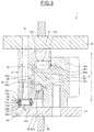
- FIG. 3 is partial cross section of a rotative assembly having a roller bearing according to a second embodiment of the invention.
- FIGS. 1 and 2 A first embodiment of a rotative assembly 1 is illustrated on FIGS. 1 and 2 , the assembly may for example be used in a tunnel boring machine, an oil pumping installation or any other applications using a large diameter rolling bearing.
- the rotative assembly 1 comprises roller bearing 10 having a rotatable first ring 12 and a non-rotatable second ring 14 which are arranged concentrically about a first rotation axis X-X′ running in an axial direction.
- the rotatable first ring 12 is configured to rotate with respect to the non-rotatable second ring 14 around the rotation axis X-X′.
- the rotatable first ring 12 is the outer ring of the rotative assembly whereas the non-rotatable second ring 14 is the inner ring of the roller bearing 10 .
- the rotatable first ring could be the inner ring of the rotative assembly whereas the non-rotatable second ring could be the outer ring of the rotative assembly.
- the non-rotatable second ring 14 comprises a protruding element or lobe 18 extending towards the rotatable first ring 12 and arranged in the circumferential groove 16 of the rotatable first ring 12 .
- a single radial roller bearing 20 having a row of radial cylindrical rollers 20 a having a rotation axis X 1 -X 1 ′ parallel to the first rotation axis X-X′ of the roller bearing 10 .
- the rollers are in this case arranged in a depression 16 a of the groove 16 .
- a corresponding depression may also be provided in the end surface 18 a of the lobe 18 .
- the radial rollers 20 a roll between raceways 16 a , 18 a provided respectively on the groove 16 and the lobe 18 .
- the rotation axis of the radial roller bearing 20 is coaxial with the rotation axis X-X′.
- the end surface 18 a of the lobe 18 forms a raceway for the radial rollers 20 a.
- Two axial roller bearings 22 , 24 each having a row of axial cylindrical rollers 22 a , 24 a spaced apart in the axial direction respectively on opposite radial faces 18 b , 18 c of the lobe 18 .
- the cylindrical rollers 22 a of the first axial roller bearing 22 have a rotation axis Y 1 -Y 1 ′ perpendicular to the rotation axis X-X′ of the roller bearing 10 .
- the outer cylindrical surface of each first axial cylindrical roller 22 a rolls between raceways 16 b , 18 b provided respectively on the groove 16 and the lobe 18 .
- the first radial face 18 b of the lobe 18 forms a raceway for the first axial cylindrical roller 22 a .
- the cylindrical rollers 24 a of the second axial roller bearing 24 have a rotation axis Y 2 -Y 2 ′ perpendicular to the rotation axis X-X′ of the roller bearing 10 .
- the roller bearing 10 comprises a plurality of circumferentially spaced apart cam followers 30 secured to the rotatable first ring 12 .
- Each cam follower 30 comprises an outer ring 32 and a stud 34 forming an inner ring arranged concentrically about a rotation axis X 2 -X 2 ′ running in an axial direction parallel to the axis of rotation X-X′ of the roller bearing 10 .
- a set of needle rollers 36 are provided between raceways 32 a , 34 a respectively of the inner cylindrical surface of the outer ring 32 and the outer cylindrical surface of the stud 34 .
- the stud 34 is secured in the rotatable first ring 12 , notably on a lower radial surface 16 d .
- the outer rings 32 are thus not in direct contact with the studs 34 , since needle rollers 36 mobile compared to the outer rings are disposed between the outer rings 32 and the studs 34 .
- the axis X 2 -X 2 ′ of the raceway is offset compared to the axis of the raceway 14 d of the axial projection 14 c.
- cam followers 30 could be arranged on a circumferential portion of the rotatable ring comprised between 15° and 120° or on the whole circumference of the rotatable ring 12 .
- the rotatable ring 12 is divided in the axial direction in two parts 12 a , 12 b , a support part 12 a to which is rotatably secured the cam followers 30 and a holding part 12 b secured at one end to the support part 12 a and at the opposite end to a rotating component 38 , on a side opposite to the cam followers 30 .
- the non-rotatable ring 14 is also divided in the axial direction in a first part 14 a forming a toothing ring and a second part 14 b secured to a fixed component 39 .
- the second part 14 b comprises an axial projection 14 c extending towards the rotatable ring 12 and onto which bears radially the outer cylindrical surface 34 b of the outer rings 34 of the cam followers 30 in case of radial deformation of the rotatable ring 12 .
- non-rotatable ring 14 is in a one piece toothed ring 14 a secured to a fixed/non-rotatable component 39 having an axial projection 39 a extending towards the rotatable ring 12 and onto which bears radially the outer rings of the cam followers in case of radial deformation of the rotatable ring 12 .
- the rotatable ring in this case the outer ring cannot be locally separated in an outward direction from the non-rotatable ring in case of radial load leading to radial deformation of the outer ring.
Landscapes
- Engineering & Computer Science (AREA)
- General Engineering & Computer Science (AREA)
- Mechanical Engineering (AREA)
- Rolling Contact Bearings (AREA)
Abstract
Description
Claims (10)
Applications Claiming Priority (3)
| Application Number | Priority Date | Filing Date | Title |
|---|---|---|---|
| DE102017219823 | 2017-11-08 | ||
| DE102017219823.0 | 2017-11-08 | ||
| DE102017219823.0A DE102017219823A1 (en) | 2017-11-08 | 2017-11-08 | Rolling bearing for supporting a radial deformation of the rolling bearing and rotating assembly having such a rolling bearing |
Publications (2)
| Publication Number | Publication Date |
|---|---|
| US20190136910A1 US20190136910A1 (en) | 2019-05-09 |
| US10690182B2 true US10690182B2 (en) | 2020-06-23 |
Family
ID=66179261
Family Applications (1)
| Application Number | Title | Priority Date | Filing Date |
|---|---|---|---|
| US16/115,710 Active US10690182B2 (en) | 2017-11-08 | 2018-08-29 | Roller bearing for supporting radial deformation of the roller bearing, and rotative assembly comprising such roller bearing |
Country Status (3)
| Country | Link |
|---|---|
| US (1) | US10690182B2 (en) |
| CN (1) | CN109751338B (en) |
| DE (1) | DE102017219823A1 (en) |
Families Citing this family (3)
| Publication number | Priority date | Publication date | Assignee | Title |
|---|---|---|---|---|
| EP3771842B1 (en) * | 2019-08-02 | 2023-12-13 | General Electric Renovables España S.L. | Roller pitch bearings |
| CN115070662B (en) * | 2021-03-15 | 2024-01-12 | 中国航发商用航空发动机有限责任公司 | Blade baffle ring mounting tool of turbine disk assembly |
| CN114483772B (en) * | 2022-01-25 | 2023-10-31 | 中国铁建重工集团股份有限公司 | Slewing bearing with high bearing capacity |
Citations (10)
| Publication number | Priority date | Publication date | Assignee | Title |
|---|---|---|---|---|
| US20090175724A1 (en) * | 2005-06-06 | 2009-07-09 | Erich Russ | Bearing unit for a long rotor blade of a wind power installation, wind power installation comprising one such rotor blade bearing arrangement, and method for operating one such wind power installation |
| US20090324151A1 (en) * | 2008-06-30 | 2009-12-31 | Nucor Corporation | Slew bearing system |
| US20110115233A1 (en) * | 2008-02-18 | 2011-05-19 | Schroeppel Werner | Wind power plant and method for operating the same |
| EP2092204B1 (en) | 2006-11-16 | 2012-08-15 | Rothe Erde GmbH | Rolling bearing, in particular centreless large rolling bearing |
| US20140010492A1 (en) * | 2012-07-04 | 2014-01-09 | Aktiebolaget Skf | Roller bearing for a tunneller |
| US20150078698A1 (en) * | 2013-09-18 | 2015-03-19 | Aktiebolaget Skf | Rolling bearing assembly |
| US20150098669A1 (en) * | 2013-09-27 | 2015-04-09 | Aktiebolaget Skf | Rotative Assembly, Method For Dismounting A Sealing Element And Extraction Tool For Dismounting A Sealing Element |
| US20160084312A1 (en) * | 2013-05-20 | 2016-03-24 | Thk Co., Ltd. | Double-row roller bearing |
| US20160245333A1 (en) * | 2013-10-18 | 2016-08-25 | Liebherr-Components Biberach Gmbh | Rolling bearing |
| US9605709B2 (en) | 2013-01-23 | 2017-03-28 | Thyssenkrupp Rothe Erde Gmbh | Cylindrical roller bearing |
Family Cites Families (4)
| Publication number | Priority date | Publication date | Assignee | Title |
|---|---|---|---|---|
| DE102011081486A1 (en) * | 2011-08-24 | 2013-02-28 | Mahle International Gmbh | crankcase |
| CN204553552U (en) * | 2015-03-10 | 2015-08-12 | 洛阳新强联回转支承股份有限公司 | A kind of three-row roller turntable bearing with axial pretightening |
| CN205047658U (en) * | 2015-10-14 | 2016-02-24 | 马鞍山统力回转支承有限公司 | Double ball formula slewing bearing of abnormal shape |
| JP2017198287A (en) * | 2016-04-27 | 2017-11-02 | 昌弘 町田 | Drive transmission mechanism and machine device utilizing drive transmission mechanism |
-
2017
- 2017-11-08 DE DE102017219823.0A patent/DE102017219823A1/en active Pending
-
2018
- 2018-08-29 US US16/115,710 patent/US10690182B2/en active Active
- 2018-10-10 CN CN201811176459.1A patent/CN109751338B/en active Active
Patent Citations (10)
| Publication number | Priority date | Publication date | Assignee | Title |
|---|---|---|---|---|
| US20090175724A1 (en) * | 2005-06-06 | 2009-07-09 | Erich Russ | Bearing unit for a long rotor blade of a wind power installation, wind power installation comprising one such rotor blade bearing arrangement, and method for operating one such wind power installation |
| EP2092204B1 (en) | 2006-11-16 | 2012-08-15 | Rothe Erde GmbH | Rolling bearing, in particular centreless large rolling bearing |
| US20110115233A1 (en) * | 2008-02-18 | 2011-05-19 | Schroeppel Werner | Wind power plant and method for operating the same |
| US20090324151A1 (en) * | 2008-06-30 | 2009-12-31 | Nucor Corporation | Slew bearing system |
| US20140010492A1 (en) * | 2012-07-04 | 2014-01-09 | Aktiebolaget Skf | Roller bearing for a tunneller |
| US9605709B2 (en) | 2013-01-23 | 2017-03-28 | Thyssenkrupp Rothe Erde Gmbh | Cylindrical roller bearing |
| US20160084312A1 (en) * | 2013-05-20 | 2016-03-24 | Thk Co., Ltd. | Double-row roller bearing |
| US20150078698A1 (en) * | 2013-09-18 | 2015-03-19 | Aktiebolaget Skf | Rolling bearing assembly |
| US20150098669A1 (en) * | 2013-09-27 | 2015-04-09 | Aktiebolaget Skf | Rotative Assembly, Method For Dismounting A Sealing Element And Extraction Tool For Dismounting A Sealing Element |
| US20160245333A1 (en) * | 2013-10-18 | 2016-08-25 | Liebherr-Components Biberach Gmbh | Rolling bearing |
Also Published As
| Publication number | Publication date |
|---|---|
| CN109751338A (en) | 2019-05-14 |
| DE102017219823A1 (en) | 2019-05-09 |
| CN109751338B (en) | 2022-01-04 |
| US20190136910A1 (en) | 2019-05-09 |
Similar Documents
| Publication | Publication Date | Title |
|---|---|---|
| US9605709B2 (en) | Cylindrical roller bearing | |
| US10690182B2 (en) | Roller bearing for supporting radial deformation of the roller bearing, and rotative assembly comprising such roller bearing | |
| US9541126B2 (en) | Large rolling bearing | |
| US10690181B2 (en) | Angular contact roller bearing and method and device for the assembly thereof | |
| US8573851B2 (en) | Needle roller bearing with rimless inner ring | |
| US11319989B2 (en) | Rolling bearing, notably large-diameter rolling bearing | |
| US8794841B2 (en) | Toroidal bearing | |
| US9771982B2 (en) | Wheel bearing arrangement for a vehicle | |
| US10683890B2 (en) | Roller bearing for supporting radial deformation of the roller bearing and rotative assembly comprising such roller bearing | |
| CN107654493B (en) | Rolling bearing comprising a mounting flange | |
| US10570960B2 (en) | Segmented cage for rolling bearing | |
| CN112460148B (en) | Rolling bearing and method for mounting same | |
| US20160061258A1 (en) | Needle bearing with a cage and a retaining tab formed on the cage | |
| TWI712750B (en) | Roller bearing | |
| US9903412B2 (en) | Tapered roller bearing | |
| CN113251077A (en) | Rolling bearing, in particular large-diameter rolling bearing | |
| US11767881B2 (en) | Rolling-element bearing, notably large-diameter rolling-element bearing | |
| US20220065296A1 (en) | Cage segment for rolling-element bearing, in particular a large-diameter rolling-element bearing | |
| US11428268B2 (en) | Rolling bearing with wire races and retaining rib | |
| US11248655B2 (en) | Rolling bearing with wire races | |
| US11396909B2 (en) | Expandable stacked thrust bearing assembly | |
| US20240183388A1 (en) | Rolling bearing with protruding nose and gear | |
| JP2013015201A (en) | Conical bearing | |
| US20230160421A1 (en) | Rolling bearing, notably large-diameter rolling bearing | |
| US20160201720A1 (en) | Double-row spherical roller bearing |
Legal Events
| Date | Code | Title | Description |
|---|---|---|---|
| FEPP | Fee payment procedure |
Free format text: ENTITY STATUS SET TO UNDISCOUNTED (ORIGINAL EVENT CODE: BIG.); ENTITY STATUS OF PATENT OWNER: LARGE ENTITY |
|
| STPP | Information on status: patent application and granting procedure in general |
Free format text: DOCKETED NEW CASE - READY FOR EXAMINATION |
|
| STPP | Information on status: patent application and granting procedure in general |
Free format text: NON FINAL ACTION MAILED |
|
| STPP | Information on status: patent application and granting procedure in general |
Free format text: NOTICE OF ALLOWANCE MAILED -- APPLICATION RECEIVED IN OFFICE OF PUBLICATIONS |
|
| STPP | Information on status: patent application and granting procedure in general |
Free format text: AWAITING TC RESP., ISSUE FEE NOT PAID |
|
| STPP | Information on status: patent application and granting procedure in general |
Free format text: NOTICE OF ALLOWANCE MAILED -- APPLICATION RECEIVED IN OFFICE OF PUBLICATIONS |
|
| STPP | Information on status: patent application and granting procedure in general |
Free format text: DOCKETED NEW CASE - READY FOR EXAMINATION |
|
| STPP | Information on status: patent application and granting procedure in general |
Free format text: NOTICE OF ALLOWANCE MAILED -- APPLICATION RECEIVED IN OFFICE OF PUBLICATIONS |
|
| STCF | Information on status: patent grant |
Free format text: PATENTED CASE |
|
| MAFP | Maintenance fee payment |
Free format text: PAYMENT OF MAINTENANCE FEE, 4TH YEAR, LARGE ENTITY (ORIGINAL EVENT CODE: M1551); ENTITY STATUS OF PATENT OWNER: LARGE ENTITY Year of fee payment: 4 |