US10661812B2 - Display device - Google Patents
Display device Download PDFInfo
- Publication number
- US10661812B2 US10661812B2 US16/053,876 US201816053876A US10661812B2 US 10661812 B2 US10661812 B2 US 10661812B2 US 201816053876 A US201816053876 A US 201816053876A US 10661812 B2 US10661812 B2 US 10661812B2
- Authority
- US
- United States
- Prior art keywords
- engine
- display
- state
- control unit
- driving source
- Prior art date
- Legal status (The legal status is an assumption and is not a legal conclusion. Google has not performed a legal analysis and makes no representation as to the accuracy of the status listed.)
- Active
Links
- 230000008929 regeneration Effects 0.000 claims abstract description 46
- 238000011069 regeneration method Methods 0.000 claims abstract description 46
- 239000000446 fuel Substances 0.000 claims abstract description 26
- 230000001133 acceleration Effects 0.000 claims description 12
- 238000010586 diagram Methods 0.000 description 33
- 238000000034 method Methods 0.000 description 16
- 230000005611 electricity Effects 0.000 description 12
- 239000002699 waste material Substances 0.000 description 12
- 238000010248 power generation Methods 0.000 description 9
- 238000002347 injection Methods 0.000 description 7
- 239000007924 injection Substances 0.000 description 7
- 238000005401 electroluminescence Methods 0.000 description 2
- 238000012986 modification Methods 0.000 description 2
- 230000004048 modification Effects 0.000 description 2
- 230000000737 periodic effect Effects 0.000 description 2
- 238000004092 self-diagnosis Methods 0.000 description 2
- 238000006467 substitution reaction Methods 0.000 description 2
- HBBGRARXTFLTSG-UHFFFAOYSA-N Lithium ion Chemical compound [Li+] HBBGRARXTFLTSG-UHFFFAOYSA-N 0.000 description 1
- 238000007792 addition Methods 0.000 description 1
- 230000005540 biological transmission Effects 0.000 description 1
- 238000004040 coloring Methods 0.000 description 1
- 238000002485 combustion reaction Methods 0.000 description 1
- 238000005516 engineering process Methods 0.000 description 1
- 239000012530 fluid Substances 0.000 description 1
- 230000006870 function Effects 0.000 description 1
- 230000010354 integration Effects 0.000 description 1
- 239000004973 liquid crystal related substance Substances 0.000 description 1
- 229910001416 lithium ion Inorganic materials 0.000 description 1
Images


Classifications
-
- B—PERFORMING OPERATIONS; TRANSPORTING
- B60—VEHICLES IN GENERAL
- B60K—ARRANGEMENT OR MOUNTING OF PROPULSION UNITS OR OF TRANSMISSIONS IN VEHICLES; ARRANGEMENT OR MOUNTING OF PLURAL DIVERSE PRIME-MOVERS IN VEHICLES; AUXILIARY DRIVES FOR VEHICLES; INSTRUMENTATION OR DASHBOARDS FOR VEHICLES; ARRANGEMENTS IN CONNECTION WITH COOLING, AIR INTAKE, GAS EXHAUST OR FUEL SUPPLY OF PROPULSION UNITS IN VEHICLES
- B60K35/00—Instruments specially adapted for vehicles; Arrangement of instruments in or on vehicles
- B60K35/20—Output arrangements, i.e. from vehicle to user, associated with vehicle functions or specially adapted therefor
- B60K35/21—Output arrangements, i.e. from vehicle to user, associated with vehicle functions or specially adapted therefor using visual output, e.g. blinking lights or matrix displays
- B60K35/22—Display screens
-
- B—PERFORMING OPERATIONS; TRANSPORTING
- B60—VEHICLES IN GENERAL
- B60K—ARRANGEMENT OR MOUNTING OF PROPULSION UNITS OR OF TRANSMISSIONS IN VEHICLES; ARRANGEMENT OR MOUNTING OF PLURAL DIVERSE PRIME-MOVERS IN VEHICLES; AUXILIARY DRIVES FOR VEHICLES; INSTRUMENTATION OR DASHBOARDS FOR VEHICLES; ARRANGEMENTS IN CONNECTION WITH COOLING, AIR INTAKE, GAS EXHAUST OR FUEL SUPPLY OF PROPULSION UNITS IN VEHICLES
- B60K6/00—Arrangement or mounting of plural diverse prime-movers for mutual or common propulsion, e.g. hybrid propulsion systems comprising electric motors and internal combustion engines ; Control systems therefor, i.e. systems controlling two or more prime movers, or controlling one of these prime movers and any of the transmission, drive or drive units Informative references: mechanical gearings with secondary electric drive F16H3/72; arrangements for handling mechanical energy structurally associated with the dynamo-electric machine H02K7/00; machines comprising structurally interrelated motor and generator parts H02K51/00; dynamo-electric machines not otherwise provided for in H02K see H02K99/00
- B60K6/20—Arrangement or mounting of plural diverse prime-movers for mutual or common propulsion, e.g. hybrid propulsion systems comprising electric motors and internal combustion engines ; Control systems therefor, i.e. systems controlling two or more prime movers, or controlling one of these prime movers and any of the transmission, drive or drive units Informative references: mechanical gearings with secondary electric drive F16H3/72; arrangements for handling mechanical energy structurally associated with the dynamo-electric machine H02K7/00; machines comprising structurally interrelated motor and generator parts H02K51/00; dynamo-electric machines not otherwise provided for in H02K see H02K99/00 the prime-movers consisting of electric motors and internal combustion engines, e.g. HEVs
- B60K6/42—Arrangement or mounting of plural diverse prime-movers for mutual or common propulsion, e.g. hybrid propulsion systems comprising electric motors and internal combustion engines ; Control systems therefor, i.e. systems controlling two or more prime movers, or controlling one of these prime movers and any of the transmission, drive or drive units Informative references: mechanical gearings with secondary electric drive F16H3/72; arrangements for handling mechanical energy structurally associated with the dynamo-electric machine H02K7/00; machines comprising structurally interrelated motor and generator parts H02K51/00; dynamo-electric machines not otherwise provided for in H02K see H02K99/00 the prime-movers consisting of electric motors and internal combustion engines, e.g. HEVs characterised by the architecture of the hybrid electric vehicle
- B60K6/44—Series-parallel type
- B60K6/442—Series-parallel switching type
-
- B—PERFORMING OPERATIONS; TRANSPORTING
- B60—VEHICLES IN GENERAL
- B60W—CONJOINT CONTROL OF VEHICLE SUB-UNITS OF DIFFERENT TYPE OR DIFFERENT FUNCTION; CONTROL SYSTEMS SPECIALLY ADAPTED FOR HYBRID VEHICLES; ROAD VEHICLE DRIVE CONTROL SYSTEMS FOR PURPOSES NOT RELATED TO THE CONTROL OF A PARTICULAR SUB-UNIT
- B60W20/00—Control systems specially adapted for hybrid vehicles
- B60W20/10—Controlling the power contribution of each of the prime movers to meet required power demand
- B60W20/13—Controlling the power contribution of each of the prime movers to meet required power demand in order to stay within battery power input or output limits; in order to prevent overcharging or battery depletion
-
- B—PERFORMING OPERATIONS; TRANSPORTING
- B60—VEHICLES IN GENERAL
- B60W—CONJOINT CONTROL OF VEHICLE SUB-UNITS OF DIFFERENT TYPE OR DIFFERENT FUNCTION; CONTROL SYSTEMS SPECIALLY ADAPTED FOR HYBRID VEHICLES; ROAD VEHICLE DRIVE CONTROL SYSTEMS FOR PURPOSES NOT RELATED TO THE CONTROL OF A PARTICULAR SUB-UNIT
- B60W50/00—Details of control systems for road vehicle drive control not related to the control of a particular sub-unit, e.g. process diagnostic or vehicle driver interfaces
- B60W50/08—Interaction between the driver and the control system
- B60W50/14—Means for informing the driver, warning the driver or prompting a driver intervention
-
- B—PERFORMING OPERATIONS; TRANSPORTING
- B60—VEHICLES IN GENERAL
- B60K—ARRANGEMENT OR MOUNTING OF PROPULSION UNITS OR OF TRANSMISSIONS IN VEHICLES; ARRANGEMENT OR MOUNTING OF PLURAL DIVERSE PRIME-MOVERS IN VEHICLES; AUXILIARY DRIVES FOR VEHICLES; INSTRUMENTATION OR DASHBOARDS FOR VEHICLES; ARRANGEMENTS IN CONNECTION WITH COOLING, AIR INTAKE, GAS EXHAUST OR FUEL SUPPLY OF PROPULSION UNITS IN VEHICLES
- B60K6/00—Arrangement or mounting of plural diverse prime-movers for mutual or common propulsion, e.g. hybrid propulsion systems comprising electric motors and internal combustion engines ; Control systems therefor, i.e. systems controlling two or more prime movers, or controlling one of these prime movers and any of the transmission, drive or drive units Informative references: mechanical gearings with secondary electric drive F16H3/72; arrangements for handling mechanical energy structurally associated with the dynamo-electric machine H02K7/00; machines comprising structurally interrelated motor and generator parts H02K51/00; dynamo-electric machines not otherwise provided for in H02K see H02K99/00
- B60K6/20—Arrangement or mounting of plural diverse prime-movers for mutual or common propulsion, e.g. hybrid propulsion systems comprising electric motors and internal combustion engines ; Control systems therefor, i.e. systems controlling two or more prime movers, or controlling one of these prime movers and any of the transmission, drive or drive units Informative references: mechanical gearings with secondary electric drive F16H3/72; arrangements for handling mechanical energy structurally associated with the dynamo-electric machine H02K7/00; machines comprising structurally interrelated motor and generator parts H02K51/00; dynamo-electric machines not otherwise provided for in H02K see H02K99/00 the prime-movers consisting of electric motors and internal combustion engines, e.g. HEVs
- B60K6/42—Arrangement or mounting of plural diverse prime-movers for mutual or common propulsion, e.g. hybrid propulsion systems comprising electric motors and internal combustion engines ; Control systems therefor, i.e. systems controlling two or more prime movers, or controlling one of these prime movers and any of the transmission, drive or drive units Informative references: mechanical gearings with secondary electric drive F16H3/72; arrangements for handling mechanical energy structurally associated with the dynamo-electric machine H02K7/00; machines comprising structurally interrelated motor and generator parts H02K51/00; dynamo-electric machines not otherwise provided for in H02K see H02K99/00 the prime-movers consisting of electric motors and internal combustion engines, e.g. HEVs characterised by the architecture of the hybrid electric vehicle
- B60K6/48—Parallel type
- B60K2006/4808—Electric machine connected or connectable to gearbox output shaft
-
- B60K2370/152—
-
- B—PERFORMING OPERATIONS; TRANSPORTING
- B60—VEHICLES IN GENERAL
- B60K—ARRANGEMENT OR MOUNTING OF PROPULSION UNITS OR OF TRANSMISSIONS IN VEHICLES; ARRANGEMENT OR MOUNTING OF PLURAL DIVERSE PRIME-MOVERS IN VEHICLES; AUXILIARY DRIVES FOR VEHICLES; INSTRUMENTATION OR DASHBOARDS FOR VEHICLES; ARRANGEMENTS IN CONNECTION WITH COOLING, AIR INTAKE, GAS EXHAUST OR FUEL SUPPLY OF PROPULSION UNITS IN VEHICLES
- B60K6/00—Arrangement or mounting of plural diverse prime-movers for mutual or common propulsion, e.g. hybrid propulsion systems comprising electric motors and internal combustion engines ; Control systems therefor, i.e. systems controlling two or more prime movers, or controlling one of these prime movers and any of the transmission, drive or drive units Informative references: mechanical gearings with secondary electric drive F16H3/72; arrangements for handling mechanical energy structurally associated with the dynamo-electric machine H02K7/00; machines comprising structurally interrelated motor and generator parts H02K51/00; dynamo-electric machines not otherwise provided for in H02K see H02K99/00
- B60K6/20—Arrangement or mounting of plural diverse prime-movers for mutual or common propulsion, e.g. hybrid propulsion systems comprising electric motors and internal combustion engines ; Control systems therefor, i.e. systems controlling two or more prime movers, or controlling one of these prime movers and any of the transmission, drive or drive units Informative references: mechanical gearings with secondary electric drive F16H3/72; arrangements for handling mechanical energy structurally associated with the dynamo-electric machine H02K7/00; machines comprising structurally interrelated motor and generator parts H02K51/00; dynamo-electric machines not otherwise provided for in H02K see H02K99/00 the prime-movers consisting of electric motors and internal combustion engines, e.g. HEVs
- B60K6/42—Arrangement or mounting of plural diverse prime-movers for mutual or common propulsion, e.g. hybrid propulsion systems comprising electric motors and internal combustion engines ; Control systems therefor, i.e. systems controlling two or more prime movers, or controlling one of these prime movers and any of the transmission, drive or drive units Informative references: mechanical gearings with secondary electric drive F16H3/72; arrangements for handling mechanical energy structurally associated with the dynamo-electric machine H02K7/00; machines comprising structurally interrelated motor and generator parts H02K51/00; dynamo-electric machines not otherwise provided for in H02K see H02K99/00 the prime-movers consisting of electric motors and internal combustion engines, e.g. HEVs characterised by the architecture of the hybrid electric vehicle
- B60K6/48—Parallel type
- B60K6/485—Motor-assist type
-
- B—PERFORMING OPERATIONS; TRANSPORTING
- B60—VEHICLES IN GENERAL
- B60L—PROPULSION OF ELECTRICALLY-PROPELLED VEHICLES; SUPPLYING ELECTRIC POWER FOR AUXILIARY EQUIPMENT OF ELECTRICALLY-PROPELLED VEHICLES; ELECTRODYNAMIC BRAKE SYSTEMS FOR VEHICLES IN GENERAL; MAGNETIC SUSPENSION OR LEVITATION FOR VEHICLES; MONITORING OPERATING VARIABLES OF ELECTRICALLY-PROPELLED VEHICLES; ELECTRIC SAFETY DEVICES FOR ELECTRICALLY-PROPELLED VEHICLES
- B60L2250/00—Driver interactions
- B60L2250/16—Driver interactions by display
-
- B—PERFORMING OPERATIONS; TRANSPORTING
- B60—VEHICLES IN GENERAL
- B60R—VEHICLES, VEHICLE FITTINGS, OR VEHICLE PARTS, NOT OTHERWISE PROVIDED FOR
- B60R16/00—Electric or fluid circuits specially adapted for vehicles and not otherwise provided for; Arrangement of elements of electric or fluid circuits specially adapted for vehicles and not otherwise provided for
- B60R16/02—Electric or fluid circuits specially adapted for vehicles and not otherwise provided for; Arrangement of elements of electric or fluid circuits specially adapted for vehicles and not otherwise provided for electric constitutive elements
- B60R16/023—Electric or fluid circuits specially adapted for vehicles and not otherwise provided for; Arrangement of elements of electric or fluid circuits specially adapted for vehicles and not otherwise provided for electric constitutive elements for transmission of signals between vehicle parts or subsystems
- B60R16/0231—Circuits relating to the driving or the functioning of the vehicle
-
- B—PERFORMING OPERATIONS; TRANSPORTING
- B60—VEHICLES IN GENERAL
- B60W—CONJOINT CONTROL OF VEHICLE SUB-UNITS OF DIFFERENT TYPE OR DIFFERENT FUNCTION; CONTROL SYSTEMS SPECIALLY ADAPTED FOR HYBRID VEHICLES; ROAD VEHICLE DRIVE CONTROL SYSTEMS FOR PURPOSES NOT RELATED TO THE CONTROL OF A PARTICULAR SUB-UNIT
- B60W50/00—Details of control systems for road vehicle drive control not related to the control of a particular sub-unit, e.g. process diagnostic or vehicle driver interfaces
- B60W50/08—Interaction between the driver and the control system
- B60W50/14—Means for informing the driver, warning the driver or prompting a driver intervention
- B60W2050/146—Display means
-
- Y—GENERAL TAGGING OF NEW TECHNOLOGICAL DEVELOPMENTS; GENERAL TAGGING OF CROSS-SECTIONAL TECHNOLOGIES SPANNING OVER SEVERAL SECTIONS OF THE IPC; TECHNICAL SUBJECTS COVERED BY FORMER USPC CROSS-REFERENCE ART COLLECTIONS [XRACs] AND DIGESTS
- Y02—TECHNOLOGIES OR APPLICATIONS FOR MITIGATION OR ADAPTATION AGAINST CLIMATE CHANGE
- Y02T—CLIMATE CHANGE MITIGATION TECHNOLOGIES RELATED TO TRANSPORTATION
- Y02T10/00—Road transport of goods or passengers
- Y02T10/60—Other road transportation technologies with climate change mitigation effect
- Y02T10/62—Hybrid vehicles
Definitions
- the present invention relates to a display device.
- a hybrid vehicle including an engine and a traveling motor is wide spread.
- a flow of energy flowing among an engine, a motor, a battery, and the like is displayed on a display device provided in an instrument panel and the like (for example, refer to Japanese Unexamined Patent Application, First Publication No. 2017-95048).
- the content of such a display may be referred to as an energy flow.
- an occupant may be informed whether or not an engine or motor operates by turning on or off an image such as an icon.
- the image may flicker depending on control circumstances in a vehicle in some cases.
- An object of an aspect of the present invention is to provide a display device capable of suppressing occurrence of flickering of an image.
- An aspect of the present invention is a display device which is mounted on a vehicle including an engine, and an electric motor connected to a drive wheel, the display device including: a display unit capable of displaying a predetermined image indicating that the engine operates; and a display control unit configured to cause the display unit to display the predetermined image when the engine operates with fuel consumption, in which, when regeneration by the electric motor is performed and an operation request for causing the engine to operate occurs, the display control unit causes the display unit to display the predetermined image regardless of an operation state of the engine.
- the operation request may include an operation request other than an operation request based on an operation for an operator receiving an acceleration instruction from a driver.
- the vehicle may further include a generator connected to the engine, and, when regeneration by the electric motor is performed, an operation request for causing the engine to operate occurs, and regeneration electric power by the electric motor is consumed by the generator causing the engine to operate without depending on fuel, the display control unit may cause the display unit to display the predetermined image.
- the display control unit may determine whether or not to stop causing the display unit to display the predetermined image based on the operation state of the engine.
- a display device includes: a display unit which is mounted on a vehicle and is capable of displaying a predetermined image indicating that at least one driving source of the vehicle operates; and a display control unit configured to determine whether or not to cause the display unit to display the predetermined image in accordance with an operation state of the driving source, in which, when the operation state of the driving source is switched, the display control unit determines whether or not to cause the display unit to continue displaying the predetermined image in accordance with an operation state of the driving source at least immediately before the switching.
- the driving source may include an engine, an electric motor connected to a drive wheel, a generator connected to the engine, and a battery
- the predetermined image may be an image indicating that the engine operates
- the operation state of the driving source may include a first state in which the engine operates with fuel consumption, a second state in which the engine stops and regeneration electric power by the electric motor is stored in the battery, and a third state in which the engine stops and regeneration electric power by the electric motor is consumed by the generator causing the engine to operate without depending on fuel, in which, when the operation state of the driving source is switched among the first state, the second state, and the third state, the display control unit may determine whether or not to cause the display unit to continue displaying the predetermined image in accordance with an operation state of the driving source at least immediately before the switching.
- the display control unit may cause the display unit to continue displaying the predetermined image.
- the display control unit may cause the display unit to continue a state of not displaying the predetermined image. According to the display device according to (1) to (8) described above, it is possible to suppress occurrence of flickering of images.
- FIG. 1 is a diagram which shows an example of a configuration of a vehicle on which a display device is mounted.
- FIG. 2 is a diagram which shows an example of a functional configuration of a control unit.
- FIG. 3 is a diagram for describing switching of a traveling mode.
- FIG. 4 is a diagram which exemplifies a pattern of deceleration control mainly executed in the vehicle.
- FIG. 5 is a diagram which exemplifies a pattern of deceleration control mainly executed in the vehicle.
- FIG. 6 is a diagram which exemplifies an attachment position of a display unit.
- FIG. 7A is a diagram which exemplifies an energy flow image IMEF- 1 which can be displayed when the vehicle is at a standstill.
- FIG. 7B is a diagram which exemplifies an energy flow image IMEF- 2 which can be displayed when the vehicle is at a standstill.
- FIG. 7C is a diagram which exemplifies an energy flow image IMEF- 3 which can be displayed when the vehicle is at a standstill.
- FIG. 8 is a diagram which exemplifies an energy flow image IMEF- 4 displayed when the vehicle travels in an EV traveling mode.
- FIG. 9A is a diagram which exemplifies an energy flow image IMEF- 5 displayed when the vehicle travels in a series hybrid traveling mode.
- FIG. 9B is a diagram which exemplifies an energy flow image IMEF- 6 displayed when the vehicle travels in the series hybrid traveling mode.
- FIG. 9C is a diagram which exemplifies an energy flow image IMEF- 7 displayed when the vehicle travels in the series hybrid traveling mode.
- FIG. 10A is a diagram which exemplifies an energy flow image IMEF- 8 displayed when the vehicle travels in an engine drive traveling mode.
- FIG. 10B is a diagram which exemplifies an energy flow image IMEF- 9 displayed when the vehicle travels in the engine drive traveling mode.
- FIG. 10C is a diagram which exemplifies an energy flow image IMEF- 10 displayed when the vehicle travels in the engine drive traveling mode.
- FIG. 11A is a diagram which exemplifies an energy flow image IMEF- 11 displayed when the vehicle decelerates due to regeneration.
- FIG. 11B is a diagram which exemplifies an energy flow image IMEF- 12 displayed when the vehicle decelerates due to regeneration.
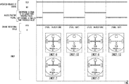
- FIG. 12 is a diagram which shows changes in display state when an acceleration instruction and a deceleration instruction are repeated in the EV traveling mode in which an operation request of an engine does not occur.
- FIG. 13 is a diagram which shows changes in display state when the acceleration instruction and the deceleration instruction are repeated in a case in which an operation request of an engine occurs.
- FIG. 14 is a flowchart which shows an example of a flow of processing executed by a display control unit when which one of the energy flow images IMEF- 11 and IMEF- 12 to display is determined.
- FIG. 15 is a flowchart which shows another example of the flow of processing executed by a display control unit when which one of the energy flow images IMEF- 11 and IMEF- 12 to display is determined.
- FIG. 1 is a diagram which shows an example of a configuration of a vehicle on which a display device 100 is mounted.
- the vehicle of the configuration shown in FIG. 1 is a hybrid vehicle capable of switching a series method and a parallel method.
- the series method is a method in which an engine and a drive wheel are not mechanically connected, the power of an engine is exclusively used for power generation by a generator, and generated electric power is supplied to an electric motor for traveling.
- the parallel method is a method in which an engine and a drive wheel can be mechanically (or via a fluid such as a torque converter) connected, and power of the engine can be transmitted to the drive wheel or used for power generation.
- a fluid such as a torque converter
- the display device 100 can be mounted on a hybrid vehicle using the series method and can be mounted on a hybrid vehicle using the parallel method.
- this vehicle may be a vehicle with a plug-in chargeable battery.
- the vehicle includes, for example, an engine 10 , a first motor (generator) 12 , a lock-up clutch 14 , a gear box 16 , a second motor (electric motor) 18 , a brake device 20 , a drive wheel 25 , a power control unit (PCU) 30 , a battery 60 , a battery sensor 62 such as a voltage sensor, a current sensor, or a temperature sensor, vehicle sensors such as an accelerator opening sensor 70 , a vehicle speed sensor 72 , and a brake pedal amount sensor 74 , and a display device 100 which are mounted thereon.
- This vehicle includes at least the engine 10 , the second motor 18 , and the battery 60 as driving sources.
- the engine 10 is an internal combustion engine that outputs power by burning fuel such as gasoline.
- the engine 10 is a reciprocating engine which includes, for example, a cylinder and a piston, an intake valve, an exhaust valve, a fuel injection device, a spark plug, a connection rod, a crankshaft, and the like.
- the engine 10 may be a rotary engine.
- the first motor 12 is, for example, a three-phase alternating current generator.
- the first motor 12 has a rotor connected to an output axis of the engine 10 (or example, crankshaft) and generates power using power output by the engine 10 .
- the output axis of the engine 10 and the rotor of the first motor 12 are connected to a side of the drive wheel 25 via the lock-up clutch 14 .
- the lock-up clutch 14 in accordance with an instruction from the PCU 30 , switches between a state in which an output axis of the engine 10 and the rotor of the first motor 12 are connected to the side of the drive wheel 25 (hereinafter, a connected state) and a state in which they are disconnected from the side of the drive wheel 25 (hereinafter, a separated state).
- the gear box 16 is a transmission.
- the gear box 16 changes a speed of power output by the engine 10 and transmits it to the side of the drive wheel 25 .
- a gear ratio of the gear box 16 is designated by the PCU 30 .
- the second motor 18 is, for example, a three-phase alternating current electric motor.
- a rotor of the second motor 18 is connected to the drive wheel 25 .
- the second motor 18 outputs power to the drive wheel 25 using supplied electric power.
- the second motor 18 generates power using kinetic energy of the vehicle.
- a power generation operation by the second motor 18 may be referred to as regeneration in some cases.
- the brake device 20 includes, for example, a brake caliper, a cylinder for transmitting a hydraulic pressure to the brake caliper, and an electric motor for generating the hydraulic pressure in the cylinder.
- the brake device 20 may include a mechanism for transmitting a hydraulic pressure generated by an operation of the brake pedal to the cylinder via a master cylinder as a backup.
- the brake device 20 is not limited to have the configuration described above, and may also be an electronically controlled hydraulic pressure brake device which transmits a hydraulic pressure of the master cylinder to the cylinder.
- the PCU 30 includes, for example, a first converter 32 , a second converter 38 , a voltage control unit (VCU) 40 , and a control unit 50 . It is merely an example that these configuration elements are formed as one unit as the PCU 30 , and these configuration elements may also be arranged in a distributed manner.
- VCU voltage control unit
- the first converter 32 and the second converter 38 are, for example, AC-DC converters. Direct current side terminals of the first converter 32 and the second converter 38 are connected to a DC link DL.
- the DC link DL is connected to the battery 60 via the VCU 40 .
- the first converter 32 converts an alternating current power generated by the first motor 12 into a direct current and outputs it to the DC link DL, or converts a direct current supplied via the DC link DL into an alternating current and supplies it to the first motor 12 .
- the second converter 38 converts an alternating current power generated by the second motor 18 into a direct current and outputs it to the DC link DL, or converts the direct current supplied via the DC link DL into an alternating current and supplies it to the second motor 18 .
- the VCU 40 is, for example, a DC-DC converter.
- the VCU 40 boosts electric power supplied from the battery 60 and outputs it to the DC link DL.
- the battery 60 is, for example, a secondary battery such as a lithium-ion battery.
- the accelerator opening sensor 70 is attached to an accelerator pedal which is an example of an operator for receiving an acceleration instruction made by a driver, detects an operation amount of the accelerator pedal, and outputs it to the control unit 50 as an accelerator opening.
- the vehicle speed sensor 72 includes, for example, a wheel speed sensor attached to each wheel, and a speed calculator, derives a speed of the vehicle (a vehicle speed) by integrating wheel speeds detected by the wheel speed sensor, and outputs it to the control unit 50 .
- the brake pedal amount sensor 74 is attached to a brake pedal which is an example of an operator for receiving a deceleration or stop instruction made by a driver, detects an operation amount of the brake pedal, and outputs it to the control unit 50 as a brake pedal amount.
- the display device 100 will be described after the control unit 50 .
- FIG. 2 is a diagram which shows an example of a functional configuration of a control unit 50 .
- the control unit 50 includes, for example, an engine control unit 51 , a motor control unit 52 , a brake control unit 53 , a battery and VCU control unit 54 , and a hybrid control unit 55 .
- These configuration elements are realized by a hardware processor such as a central processing unit (CPU) executing a program (software).
- CPU central processing unit
- part or all of these configuration elements may be realized by hardware (a circuit section; including circuitry) such as a large scale integration (LSI), an application specific integrated circuit (ASIC), a field-programmable gate array (FPGA), and a graphics processing unit (GPU), and may also be realized by cooperation of software and hardware.
- LSI large scale integration
- ASIC application specific integrated circuit
- FPGA field-programmable gate array
- GPU graphics processing unit
- each of the engine control unit 51 , the motor control unit 52 , the brake control unit 53 , and the battery and VCU control unit 54 may also be replaced with a control device separated from the hybrid control unit 55 , for example, a control device such as an engine electronic control unit (ECU), a motor ECU, a brake ECU, or a battery ECU.
- ECU engine electronic control unit
- a motor ECU motor ECU
- brake ECU brake ECU
- the engine control unit 51 performs ignition control, throttle opening control, fuel injection control, fuel cut control, and the like of the engine 10 in accordance with an instruction from the hybrid control unit 55 . Moreover, the engine control unit 51 may calculate an engine rotational speed on the basis of an output of a crank angle sensor attached to the crankshaft and output it to the hybrid control unit 55 .
- the motor control unit 52 performs switching control of the first converter 32 and/or the second converter 38 in accordance with an instruction from the hybrid control unit 55 .
- the brake control unit 53 controls the brake device 20 in accordance with an instruction from the hybrid control unit 55 .
- the battery and VCU control unit 54 calculates a state of charge (SOC; a charging rate) of the battery 60 on the basis of an output of the battery sensor 62 attached to the battery 60 and outputs it to the hybrid control unit 55 .
- the battery and VCU control unit 54 causes the VCU 40 to operate in accordance with an instruction from the hybrid control unit 55 and raises a voltage of the DC link DL.
- the hybrid control unit 55 determines a traveling mode on the basis of outputs of the accelerator opening sensor 70 , the vehicle speed sensor 72 , and the brake pedal amount sensor 74 , and outputs instructions to the engine control unit 51 , the motor control unit 52 , the brake control unit 53 , and the battery and VCU control unit 54 in accordance with a traveling mode.
- the traveling mode includes the following modes.
- the hybrid control unit 55 brings the lock-up clutch 14 into a separated state, drives the second motor 18 using electric power supplied from the battery 60 , and causes the vehicle to travel according to power from the second motor 18 .
- the hybrid control unit 55 sets the lock-up clutch 14 to the separated state, causes the engine 10 to operate by supplying fuel thereto, and supplies electric power generated by the first motor 12 to the battery 60 and the second motor 18 . Then, the second motor 18 is driven using electric power supplied from the first motor 12 or the battery 60 , and the vehicle is caused to travel using power from the second motor 18 .
- the hybrid control unit 55 sets the lock-up clutch 14 to the connected state, causes the engine 10 to operate by consuming fuel, and causes the vehicle to travel by transmitting at least part of the power output by the engine 10 to the drive wheel 25 .
- the first motor 12 may or may not perform power generation.
- the second motor 18 may or may not output an amount of power that supplies the shortfall to the drive wheel 25 .
- the engine drive traveling mode is used to realize a parallel method. The engine drive traveling mode is adopted when the speed of the vehicle is within a predetermined range of the engine 10 with good operation efficiency.
- the hybrid control unit 55 sets the lock-up clutch 14 to the separated state and causes the second motor 18 to perform power generation using the kinetic energy of the vehicle.
- Generated electric power at the time of regeneration is stored in the battery 60 , or discarded by a waste electricity operation as described below.
- FIG. 3 is a diagram for describing switching of the traveling mode.
- the vertical axis represents speed
- the horizontal axis represents a traveling distance or time.
- the hybrid control unit 55 causes the vehicle to start in, for example, the EV traveling mode, and then switches between the EV traveling mode and the series hybrid traveling mode in accordance with the SOC of the battery 60 .
- the hybrid control unit 55 switches, for example, between the EV traveling mode and the series hybrid traveling mode in accordance with the SOC of the battery 60 .
- a low noise EV traveling mode may be adopted.
- the hybrid control unit 55 causes the vehicle to travel, for example, in the series hybrid traveling mode. In the acceleration phase and a next high speed stationary travel phase, the hybrid control unit 55 improves output performance of the second motor 18 by causing the VCU 40 to operate and raising the voltage of the DC link DL.
- the hybrid control unit 55 switches, for example, between the engine drive traveling mode and the EV traveling mode.
- the engine drive traveling mode is a traveling mode adopted within a speed range in which the engine 10 can efficiently operate (for example, 60 [km/h] to 100 [km/h]).
- the EV traveling mode is adopted in a state in which the VCU 40 is operated and the voltage of the DC link DL is raised.
- the hybrid control unit 55 performs one or both of braking by regeneration and braking by the brake device 20 .
- FIGS. 4 and 5 are diagrams which exemplify patterns of deceleration control mainly executed in the vehicle.
- the second motor 18 outputs a braking force to the drive wheel 25 while performing power generation by regeneration, and electric power generated by the second motor 18 is stored in the battery 60 .
- the lock-up clutch 14 is kept in the separated state.
- the braking force may also be output to the drive wheel 25 by the brake device 20 .
- the control unit 50 outputs an instruction for causing the second motor 18 to perform regeneration to the second converter 38 , and does not output a special instruction to the first converter 32 .
- the deceleration control shown in FIG. 4 may be referred to as regeneration (charging) in some cases.
- the second motor 18 outputs a braking force to the drive wheel 25 while performing power generation by regeneration, and electric power generated by the second motor 18 is supplied to the first motor 12 .
- the first motor 12 idles the engine 10 using the supplied electric power.
- the lock-up clutch 14 is kept in the separated state.
- a braking force may also be output to the drive wheel 25 by the brake device 20 .
- the control unit 50 outputs an instruction for causing the second motor 18 to perform regeneration to the second converter 38 , and outputs an instruction for causing the first motor 12 to idle the engine 10 to the first converter 32 .
- fuel cut control is performed on the engine 10 .
- the deceleration control shown in FIG. 5 may be referred to as regeneration (waste electricity) in some cases.
- the regeneration (waste electricity) is performed when the SOC of the battery 60 is sufficiently high and no further charging is required or preferred.
- control to decelerate the vehicle may be performed by only the brake device 20 .
- the display device 100 includes a display unit 110 and a display control unit 120 .
- the display unit 110 is realized by a liquid crystal display (LCD), an organic electroluminescence (EL) display device, a head up display (HUD), and the like.
- the display control unit 120 is realized, for example, by a hardware processor such as a CPU executing a program (software).
- the display control unit 120 may be realized by hardware such as LSI&ASIC, FPGA, and GPU (a circuit section; including circuitry), or may also be realized by cooperation of software and hardware.
- the display control unit 120 acquires a state of the vehicle (an operation state of a driving source) from the control unit 50 , and determines a display image of the display unit 110 .
- the display control unit 120 may be integrated into the control unit 50 .
- FIG. 6 is a diagram which exemplifies an attachment position of the display unit 110 .
- the display unit 110 as shown in FIG. 6 may be a device ( 110 ( 1 ) in FIG. 6 ) provided in a portion of an instrument panel facing a driver to perform a display including a speedometer, and may be a device ( 110 ( 2 ) in FIG. 6 ) provided near a vehicle central axis of the instrument panel to display a navigation image and the like.
- the display unit 110 displays an energy flow image IMEF described below, for example, in an area A ( 1 ) in the speedometer.
- the display unit 110 displays the energy flow image IMEF in an arbitrary area A ( 2 ).
- An attachment position of the display unit 110 is not limited to that exemplified in FIG. 4 , and may be an arbitrary position.
- FIGS. 7A to 11B are diagrams which exemplify a mode of the energy flow image IMEF.
- Configuration elements of the energy flow image IMEF include, for example, an icon Ieg indicating that the engine 10 operates, an icon Ibt indicating that the battery 60 is being charged or power is being discharged therefrom, an icon Idw indicating a drive wheel, and a flow object Fo indicating an energy flow by animation, arrows, and the like.
- the icon Ieg and the icon Ibt indicate whether the engine 10 operates or whether the battery 60 is being charged or power is being discharged therefrom by switching between a display state and a non-display state.
- the non-display state may be replaced with a “display reduced state” in which coloring or luminance is reduced to be more inconspicuous than a display state, but the display reduced state will be described as a state included in the non-display state in the following description.
- the icon Ieg in the display state is an example of a “predetermined image.”
- the icon Idw indicating a drive wheel may be displayed all the time regardless of the state of the vehicle.
- FIGS. 7A to 7C are diagrams which exemplify energy flow images IMEF- 1 to IMEF- 3 which can be displayed when the vehicle is at a standstill.
- FIG. 7A shows an energy flow image IMEF- 1 displayed when the vehicle is stopped and the engine 10 is inactive.
- the icon Ieg and the icon Ibt are in the non-display state, and the flow object Fo is also not displayed.
- FIG. 7B shows an energy flow image IMEF- 2 displayed when any one of the first motor 12 and the second motor 18 does not perform power generation even though the vehicle is stopped and the engine 10 operates.
- the icon Ieg is displayed in the energy flow image IMEF- 2 .
- FIG. 7C shows an energy flow image IMEF- 3 displayed when the vehicle is stopped, the engine 10 operates, and the first motor 12 performs power generation.
- the icon Ieg and the icon Ibt are displayed, and further a flow object Fo heading for the icon Ibt from the icon Ieg is displayed in the energy flow image IMEF- 3 .
- FIG. 8 is a diagram which exemplifies an energy flow image IMEF- 4 displayed when the vehicle travels in the EV traveling mode.
- An icon Ibt is displayed and a flow object Fo heading for an icon Idw from the icon Ibt is displayed in the energy flow image IMEF- 4 .
- FIGS. 9A to 9C are diagrams which exemplify energy flow images IMEF- 5 to IMEF- 7 displayed when the vehicle travels in the series hybrid traveling mode.
- FIG. 9A shows an energy flow image IMEF- 5 displayed when the vehicle travels in the series hybrid traveling mode and the battery 60 is charged.
- the icon Ieg and the icon Ibt are displayed, and a flow object Fo heading for the icon Ibt and the icon Idw from the icon Ieg is displayed.
- This state is generated when the power output by the engine 10 exceeds an energy sum of power output to the drive wheel DW and consumed power of an auxiliary device such as an air conditioner.
- FIG. 9B shows an energy flow image IMEF- 6 displayed when the vehicle travels in the series hybrid traveling mode and electric power is supplied to the DC link DL from the battery 60 .
- the icon Ieg and the icon Ibt are displayed and a flow object Fo heading for the icon Idw from the icon Ieg and the icon Ibt is displayed. This state is generated when the power output by the engine 10 is lower than the energy sum of power output to the drive wheel DW and consumed power of an auxiliary device such as an air conditioner.
- FIG. 9C shows an energy flow image IMEF- 7 displayed when the vehicle travels in the series hybrid traveling mode and the battery 60 is not charged or power is not discharged therefrom.
- the icon Ieg is displayed, and a flow object Fo heading for the icon Idw from the icon Ieg is displayed. This state is generated when the power output by the engine 10 coincides with the energy sum of power output to the drive wheel DW and consumed power of an auxiliary device such as an air conditioner.
- FIGS. 10A to 10C are diagrams which exemplify an energy flow images IMEF- 8 to IMEF- 10 displayed when the vehicle travels in the engine drive traveling mode.
- FIG. 10A shows an energy flow image IMEF- 8 displayed when the vehicle travels in the engine drive traveling mode and the battery 60 is charged.
- the icon Ieg and the icon Ibt are displayed, and the flow object Fo heading for the icon Ibt and the icon Idw from the icon Ieg is displayed. This state is generated when the power output by the engine 10 exceeds an energy sum of power output to the drive wheel DW and consumed power of an auxiliary device such as an air conditioner.
- FIG. 10B shows an energy flow image IMEF- 9 displayed when the vehicle travels in the engine drive traveling mode and electric power is supplied to the DC link DL from the battery 60 .
- the icon Ieg and the icon Ibt are displayed, and the flow object Fo heading for the icon Idw from the icon Ieg and the icon Ibt is displayed. This state is generated when the power output by the engine 10 is lower than an energy sum of power output to the drive wheel DW and the consumed power of an auxiliary device such as an air conditioner.
- FIG. 10C shows an energy flow image IMEF- 10 displayed when the vehicle travels in the engine drive traveling mode and the battery 60 is not charged or power is not discharged therefrom.
- the icon Ieg is displayed, and the flow object Fo heading for the icon Idw from the icon Ieg is displayed. This state is generated when the power output by the engine 10 coincides with an energy sum of power output to the drive wheel DW and consumed power of an auxiliary device such as an air conditioner.
- FIGS. 11A to 11B are diagrams which exemplify energy flow images IMEF- 11 and IMEF- 12 displayed when the vehicle decelerates due to regeneration.
- FIG. 11A shows an energy flow image IMEF- 11 displayed when regeneration is performed and an operation request of the engine 10 does not occur.
- the icon Ibt is displayed and a flow object Fo heading for the icon Ibt from the icon Idw is displayed.
- FIG. 11B shows an energy flow image IMEF- 12 displayed when regeneration is performed and an operation request for the engine 10 occurs.
- the icon Ieg and the icon Ibt are displayed and the flow object Fo heading for the icon Ibt from the icon Idw is displayed.
- An operation request of the engine 10 may be an event occurring inside the control unit 50 , and may also be an instruction signal given to a control device of the engine 10 .
- flag information indicating whether an operation request of the engine 10 occurs is written in a predetermined region in a memory of the control unit 50 by the hybrid control unit 55 , and the engine control unit 51 processes control of the engine 10 with reference to the flag information.
- An operation request of the engine 10 occurs, for example, in the following cases.
- the display control unit 120 causes the display unit 110 to display the icon Ieg regardless of the operation state of the engine 10 when regeneration by the second motor 18 is performed and the operation request of the engine 10 occurs.
- the energy flow image IMEF- 12 is displayed instead of the energy flow image IMEF- 11 .
- the display control unit 120 may determine which of the energy flow images IMEF- 11 and IMEF- 12 to display on the basis of whether an immediately preceding state is a state in which the engine 10 operates due to fuel injection. In this case, the display control unit 120 causes the display unit 110 to display the energy flow image IMEF- 11 when an immediately preceding state is not the state in which the engine 10 operates due to fuel injection, and causes the display unit 110 to display the energy flow image IMEF- 12 when an immediately preceding state is the state in which the engine 10 operates due to fuel injection.
- the processing described above is applied only when the regeneration (waste electricity) is performed, and, when the regeneration (charging) is performed, the energy flow image IMEF- 11 may be displayed instead of the energy flow image IMEF- 12 although an operation request of the engine 10 has occurred.
- FIG. 12 is a diagram which shows changes in display state when an acceleration instruction and a deceleration instruction are repeated in the EV traveling mode in which an operation request of an engine 10 does not occur.
- regeneration (waste electricity) is performed in an accelerator pedal off period.
- the energy flow images IMEF- 4 and IMEF 11 are alternately displayed. Since the icon Ieg is not displayed in any of the energy flow image IMEF- 4 and IMEF- 11 , flickering of the icon Ieg does not occur.
- the icon Ieg is displayed when the engine 10 operates with fuel consumption. Therefore, although the engine 10 performs idling when the operation request of the engine 10 does not occur, the icon Ieg is not displayed.
- FIG. 13 is a diagram which shows changes in display state when the acceleration instruction and the deceleration instruction are repeated in a case in which the operation request of an engine 10 occurs.
- the regeneration (waste electricity) is performed in a period of accelerator pedal off.
- the energy flow image IMEF- 6 or IMEF- 7 and IMEF- 12 are alternately displayed. Since the icon Ieg is displayed in both of the energy flow image IMEF- 6 or IMEF- 7 and IMEF- 12 , flickering of the icon Ieg does not occur.
- the icon Ieg is displayed when the engine 10 operates with fuel consumption in principle, but, since the flickering of the icon Ieg occurs if the icon Ieg is set to the non-display whenever the regeneration (waste electricity) occurs in a case in which the operation request of the engine 10 does not occur, the display device 100 of the embodiment suppresses the flickering of the icon Ieg by exceptionally preparing the energy flow image IMEF- 12 . If the operation request of the engine 10 disappears while the energy flow image IMEF- 12 is displayed, it may be determined whether to switch from the energy flow image IMEF- 12 to the energy flow image IMEF- 11 on the basis of the operation state of the engine 10 .
- FIG. 14 is a flowchart which shows an example of a flow of processing executed by a display control unit 120 when which one of the energy flow images IMEF- 11 and IMEF- 12 to display is determined.
- the processing of the present flowchart is started when a vehicle state is switched to regeneration.
- the display control unit 120 determines whether the operation request of the engine 10 occurs (step S 100 ). When the operation request of the engine 10 does not occur, the display control unit 120 does not cause the display unit 110 to display the icon Ieg (step S 102 ). That is, the display control unit 120 causes the display unit 110 to display the energy flow image IMEF- 11 .
- the determination processing of step S 100 may be used to determine whether the immediately preceding state of the vehicle is a state in which the engine 10 operates due to fuel injection.
- the display control unit 120 causes the display unit 110 to display the icon Ieg (step S 104 ). That is, the display control unit 120 causes the display unit 110 to display the energy flow image IMEF- 12 .
- the display control unit 120 may also perform processing of a flowchart shown in FIG. 15 instead of the processing of the flowchart shown in FIG. 14 .
- FIG. 15 is a flowchart which shows another example of the flow of processing executed by the display control unit 120 when which one of the energy flow images IMEF- 11 and IMEF- 12 to display is determined. The processing of the present flowchart starts when the state of the vehicle is switched to regeneration.
- the display control unit 120 determines whether the operation request of the engine 10 occurs (step S 200 ). When the operation request of the engine 10 does not occur, the display control unit 120 does not cause the display unit 110 to display the icon Ieg (step S 202 ). That is, the display control unit 120 causes the display unit 110 to display the energy flow image IMEF- 11 .
- the determination processing in step S 200 may be used to determine whether the immediately preceding state of the vehicle is a state in which the engine 10 operates due to fuel injection.
- the display control unit 120 determines whether the vehicle is in a state of performing regeneration (waste electricity) (step S 204 ). When the vehicle does not perform regeneration (waste electricity), that is, regeneration (charging) is not performed, the display control unit 120 does not cause the display unit 110 to display the icon Ieg (step S 202 ). When the vehicle performs regeneration (waste electricity), the display control unit 120 causes the display unit 110 to display the icon Ieg (step S 206 ). That is, the display control unit 120 causes the display unit 110 to display the energy flow image IMEF- 12 .
- the display control unit 120 when the display control unit 120 performs regeneration using the second motor 18 and an operation request for causing the engine 10 to operate occurs, it is possible to suppress occurrence of image flickering by causing the display unit 110 to display the icon Ieg regardless of an operation state of the engine 10 .
- the display control unit 120 determining whether to cause the display unit 110 to continue displaying of the icon Ieg, when an operation state of a driving source is switched, in accordance with the operation state of a driving source at least immediately before the switching.
- a display control method for controlling a display unit which is mounted on a vehicle including an engine and an electric motor connected to a drive wheel and is capable of displaying a predetermined image indicating that the engine operates includes causing the display unit to display the predetermined image when the engine operates with fuel consumption, and causing the display unit to display the predetermined image regardless of an operation state of the engine when regeneration by the electric motor is performed and an operation request for causing the engine to operate occurs.
- a program for causing a computer to control a display unit which is mounted on the vehicle including an engine, and an electric motor connected to a drive wheel and is capable of displaying a predetermined image indicating that the engine operates causes the computer to execute processing of causing the display unit to display the predetermined image when the engine operates with fuel consumption, and processing of causing the display unit to display the predetermined image regardless of an operation state of the engine when regeneration by the electric motor is performed and an operation request for causing the engine to operate occurs.
- a display control method of controlling a display unit that is mounted on a vehicle and is capable of displaying a predetermined image indicating that at least one driving source of the vehicle operates the method include determining whether to cause the display unit to display the predetermined image in accordance with an operation state of the driving source, and determining, when the operation state of the driving source is switched, whether to cause the display unit to continue displaying the predetermined image in accordance with an operation state of the driving source at least immediately before the switching.
- a program for causing a computer to control a display unit that is mounted on a vehicle and is capable of displaying a predetermined image indicating that at least one driving source of the vehicle operates the program causes the computer to execute processing of determining whether to cause the display unit to display the predetermined image in accordance with the operation state of the driving source, and processing of determining, when the operation state of the driving source is switched, whether to cause the display unit to continue displaying the predetermined image in accordance with an operation state of the driving source at least immediately before the switching.
Landscapes
- Engineering & Computer Science (AREA)
- Transportation (AREA)
- Mechanical Engineering (AREA)
- Chemical & Material Sciences (AREA)
- Combustion & Propulsion (AREA)
- Automation & Control Theory (AREA)
- Human Computer Interaction (AREA)
- Hybrid Electric Vehicles (AREA)
- Electric Propulsion And Braking For Vehicles (AREA)
- Instrument Panels (AREA)
Abstract
Description
Claims (6)
Applications Claiming Priority (2)
| Application Number | Priority Date | Filing Date | Title |
|---|---|---|---|
| JP2017-155160 | 2017-08-10 | ||
| JP2017155160A JP6653297B2 (en) | 2017-08-10 | 2017-08-10 | Display device |
Publications (2)
| Publication Number | Publication Date |
|---|---|
| US20190047589A1 US20190047589A1 (en) | 2019-02-14 |
| US10661812B2 true US10661812B2 (en) | 2020-05-26 |
Family
ID=65274702
Family Applications (1)
| Application Number | Title | Priority Date | Filing Date |
|---|---|---|---|
| US16/053,876 Active US10661812B2 (en) | 2017-08-10 | 2018-08-03 | Display device |
Country Status (3)
| Country | Link |
|---|---|
| US (1) | US10661812B2 (en) |
| JP (1) | JP6653297B2 (en) |
| CN (1) | CN109383292B (en) |
Families Citing this family (6)
| Publication number | Priority date | Publication date | Assignee | Title |
|---|---|---|---|---|
| JP7149230B2 (en) * | 2019-06-26 | 2022-10-06 | 本田技研工業株式会社 | Vehicle system and hybrid vehicle |
| JP7206168B2 (en) * | 2019-08-20 | 2023-01-17 | 本田技研工業株式会社 | Display control device, display control method, and program |
| JP7251664B2 (en) * | 2020-01-28 | 2023-04-04 | 三菱自動車工業株式会社 | Vehicle status display device |
| JP7400957B2 (en) * | 2020-04-28 | 2023-12-19 | 三菱自動車工業株式会社 | Vehicle status display device and vehicle status display method |
| CN111959493B (en) * | 2020-08-31 | 2023-05-23 | 重庆长安新能源汽车科技有限公司 | Method and device for determining energy flow of hybrid electric vehicle with series-parallel structure and vehicle |
| JP7145185B2 (en) * | 2020-09-23 | 2022-09-30 | 本田技研工業株式会社 | Display device, display control method, and program |
Citations (28)
| Publication number | Priority date | Publication date | Assignee | Title |
|---|---|---|---|---|
| US20010020554A1 (en) * | 2000-02-24 | 2001-09-13 | Takashi Yanase | Regeneration control device of hybrid electric vehicle |
| US6457351B1 (en) * | 1998-09-18 | 2002-10-01 | Nissan Motor Co., Ltd. | Hybrid electric vehicle testing method and system |
| JP2007118641A (en) | 2005-10-25 | 2007-05-17 | Toyota Motor Corp | Internal combustion engine controller, drive information display device, and apparatus for detecting and displaying rotation speed for hybrid vehicle |
| US20100276494A1 (en) * | 2007-11-02 | 2010-11-04 | Continental Automotive Gmbh | Card Reading Device For A Vehicle |
| US20100292902A1 (en) * | 2007-05-23 | 2010-11-18 | Thomas Bach | Technique for Starting a Motor Vehicle on a Downhill Route |
| US20110000725A1 (en) * | 2009-07-06 | 2011-01-06 | Suzuki Motor Corporation | Hybrid vehicle |
| WO2011030444A1 (en) | 2009-09-11 | 2011-03-17 | トヨタ自動車株式会社 | Hybrid car and method of displaying parameters of hybrid car |
| WO2011158318A1 (en) | 2010-06-14 | 2011-12-22 | トヨタ自動車株式会社 | Control device for hybrid vehicle |
| US20110320088A1 (en) * | 2010-06-29 | 2011-12-29 | Kia Motors Corporation | System and method for displaying power status of hybrid vehicle |
| JP2012126272A (en) | 2010-12-16 | 2012-07-05 | Suzuki Motor Corp | Display device of hybrid vehicle |
| WO2013021450A1 (en) | 2011-08-08 | 2013-02-14 | トヨタ自動車株式会社 | Vehicle state display device in hybrid vehicle |
| US20140058579A1 (en) * | 2012-08-23 | 2014-02-27 | Toyota Jidosha Kabushiki Kaisha | Driving assist device and driving assist method |
| US20140121956A1 (en) * | 2010-03-31 | 2014-05-01 | Fisker Automotive, Inc. | System and method for range calculation in vehicles |
| US20140288751A1 (en) * | 2011-11-07 | 2014-09-25 | Honda Motor Co., Ltd. | Display device of electric vehicle |
| WO2015040729A1 (en) | 2013-09-20 | 2015-03-26 | 日産自動車株式会社 | Hybrid vehicle control device and control method |
| US20150197162A1 (en) * | 2014-01-16 | 2015-07-16 | Ford Global Technologies, Llc | Electric vehicle rule-maker |
| US20150224995A1 (en) * | 2012-10-17 | 2015-08-13 | Toyota Jidosha Kabushiki Kaisha | Driving assistance apparatus |
| US20150233304A1 (en) * | 2012-09-04 | 2015-08-20 | Honda Motor Co., Ltd. | Internal combustion engine control system |
| US20160368473A1 (en) * | 2015-06-22 | 2016-12-22 | Fuji Jukogyo Kabushiki Kaisha | Vehicle Control Apparatus |
| US20170015328A1 (en) * | 2014-02-14 | 2017-01-19 | Toyota Jidosha Kabushiki Kaisha | Drive assist apparatus and method |
| US20170067385A1 (en) * | 2011-12-23 | 2017-03-09 | Zonar Systems, Inc. | Method and apparatus for changing vehicle behavior based on current vehicle location and zone definitions created by a remote user |
| JP2017095048A (en) | 2015-11-27 | 2017-06-01 | スズキ株式会社 | Energy flow display device and display method |
| US20180009329A1 (en) * | 2016-07-08 | 2018-01-11 | Robert Tellez | System and Method for Charging Vehicle Batteries |
| US20180238251A1 (en) * | 2015-10-21 | 2018-08-23 | Bayerische Motoren Werke Aktiengesellschaft | Method and System for Regenerating a Soot Particle Filter |
| US20180274673A1 (en) * | 2017-03-22 | 2018-09-27 | Toyota Jidosha Kabushiki Kaisha | Motor vehicle, control apparatus for motor vehicle, and control method for motor vehicle |
| US10099681B2 (en) * | 2015-09-17 | 2018-10-16 | Hyundai Motor Company | User interface apparatus of non-uniform displacement engine control system and control method of the user interface apparatus of non-uniform displacement engine control system |
| US20180340785A1 (en) * | 2017-05-26 | 2018-11-29 | Ford Global Technologies, Llc | Systems and methods for particulate filter regeneration |
| US10328927B2 (en) * | 2017-05-18 | 2019-06-25 | Mitsubishi Jidosha Kogyo Kabushiki Kaisha | Display device for hybrid vehicle |
Family Cites Families (8)
| Publication number | Priority date | Publication date | Assignee | Title |
|---|---|---|---|---|
| US8058982B2 (en) * | 2008-08-29 | 2011-11-15 | Paccar Inc | Information display systems and methods for hybrid vehicles |
| JP5493120B2 (en) * | 2009-07-29 | 2014-05-14 | 伊那食品工業株式会社 | Lipid substitutes, lipid substitutes, and low-calorie foods |
| JP2011158318A (en) * | 2010-01-29 | 2011-08-18 | Pulstec Industrial Co Ltd | Translucent substrate inspection device |
| US8502654B2 (en) * | 2010-03-17 | 2013-08-06 | Ford Global Technologies, Llc | Vehicle information display and method |
| JP5689761B2 (en) * | 2011-07-08 | 2015-03-25 | 株式会社日立製作所 | Wireless communication network system and method of selecting physical cell identifier in the system |
| EP2896543B1 (en) * | 2012-09-11 | 2021-10-20 | Honda Motor Co., Ltd. | Hybrid vehicle |
| JP2015040729A (en) * | 2013-08-21 | 2015-03-02 | 日本軽金属株式会社 | Biochip substrate and manufacturing method therefor |
| WO2016067980A1 (en) * | 2014-10-30 | 2016-05-06 | 三菱自動車工業株式会社 | Hybrid vehicle display device |
-
2017
- 2017-08-10 JP JP2017155160A patent/JP6653297B2/en active Active
-
2018
- 2018-08-02 CN CN201810874149.0A patent/CN109383292B/en active Active
- 2018-08-03 US US16/053,876 patent/US10661812B2/en active Active
Patent Citations (29)
| Publication number | Priority date | Publication date | Assignee | Title |
|---|---|---|---|---|
| US6457351B1 (en) * | 1998-09-18 | 2002-10-01 | Nissan Motor Co., Ltd. | Hybrid electric vehicle testing method and system |
| US20010020554A1 (en) * | 2000-02-24 | 2001-09-13 | Takashi Yanase | Regeneration control device of hybrid electric vehicle |
| JP2007118641A (en) | 2005-10-25 | 2007-05-17 | Toyota Motor Corp | Internal combustion engine controller, drive information display device, and apparatus for detecting and displaying rotation speed for hybrid vehicle |
| US20100292902A1 (en) * | 2007-05-23 | 2010-11-18 | Thomas Bach | Technique for Starting a Motor Vehicle on a Downhill Route |
| US20100276494A1 (en) * | 2007-11-02 | 2010-11-04 | Continental Automotive Gmbh | Card Reading Device For A Vehicle |
| US20110000725A1 (en) * | 2009-07-06 | 2011-01-06 | Suzuki Motor Corporation | Hybrid vehicle |
| WO2011030444A1 (en) | 2009-09-11 | 2011-03-17 | トヨタ自動車株式会社 | Hybrid car and method of displaying parameters of hybrid car |
| US20140121956A1 (en) * | 2010-03-31 | 2014-05-01 | Fisker Automotive, Inc. | System and method for range calculation in vehicles |
| WO2011158318A1 (en) | 2010-06-14 | 2011-12-22 | トヨタ自動車株式会社 | Control device for hybrid vehicle |
| US20110320088A1 (en) * | 2010-06-29 | 2011-12-29 | Kia Motors Corporation | System and method for displaying power status of hybrid vehicle |
| JP2012126272A (en) | 2010-12-16 | 2012-07-05 | Suzuki Motor Corp | Display device of hybrid vehicle |
| WO2013021450A1 (en) | 2011-08-08 | 2013-02-14 | トヨタ自動車株式会社 | Vehicle state display device in hybrid vehicle |
| US20140288751A1 (en) * | 2011-11-07 | 2014-09-25 | Honda Motor Co., Ltd. | Display device of electric vehicle |
| US20170067385A1 (en) * | 2011-12-23 | 2017-03-09 | Zonar Systems, Inc. | Method and apparatus for changing vehicle behavior based on current vehicle location and zone definitions created by a remote user |
| US20140058579A1 (en) * | 2012-08-23 | 2014-02-27 | Toyota Jidosha Kabushiki Kaisha | Driving assist device and driving assist method |
| US20150233304A1 (en) * | 2012-09-04 | 2015-08-20 | Honda Motor Co., Ltd. | Internal combustion engine control system |
| US20150224995A1 (en) * | 2012-10-17 | 2015-08-13 | Toyota Jidosha Kabushiki Kaisha | Driving assistance apparatus |
| WO2015040729A1 (en) | 2013-09-20 | 2015-03-26 | 日産自動車株式会社 | Hybrid vehicle control device and control method |
| US20160207520A1 (en) * | 2013-09-20 | 2016-07-21 | Nissan Motor Co., Ltd. | Hybrid vehicle control device and control method |
| US20150197162A1 (en) * | 2014-01-16 | 2015-07-16 | Ford Global Technologies, Llc | Electric vehicle rule-maker |
| US20170015328A1 (en) * | 2014-02-14 | 2017-01-19 | Toyota Jidosha Kabushiki Kaisha | Drive assist apparatus and method |
| US20160368473A1 (en) * | 2015-06-22 | 2016-12-22 | Fuji Jukogyo Kabushiki Kaisha | Vehicle Control Apparatus |
| US10099681B2 (en) * | 2015-09-17 | 2018-10-16 | Hyundai Motor Company | User interface apparatus of non-uniform displacement engine control system and control method of the user interface apparatus of non-uniform displacement engine control system |
| US20180238251A1 (en) * | 2015-10-21 | 2018-08-23 | Bayerische Motoren Werke Aktiengesellschaft | Method and System for Regenerating a Soot Particle Filter |
| JP2017095048A (en) | 2015-11-27 | 2017-06-01 | スズキ株式会社 | Energy flow display device and display method |
| US20180009329A1 (en) * | 2016-07-08 | 2018-01-11 | Robert Tellez | System and Method for Charging Vehicle Batteries |
| US20180274673A1 (en) * | 2017-03-22 | 2018-09-27 | Toyota Jidosha Kabushiki Kaisha | Motor vehicle, control apparatus for motor vehicle, and control method for motor vehicle |
| US10328927B2 (en) * | 2017-05-18 | 2019-06-25 | Mitsubishi Jidosha Kogyo Kabushiki Kaisha | Display device for hybrid vehicle |
| US20180340785A1 (en) * | 2017-05-26 | 2018-11-29 | Ford Global Technologies, Llc | Systems and methods for particulate filter regeneration |
Non-Patent Citations (2)
| Title |
|---|
| Japanese Notice of Allowance for Japanese Patent Application No. 2017-155160 dated Jan. 14, 2020. |
| Japanese Office Action for Japanese Patent Application No. 2017-155160 dated Jul. 2, 2019. |
Also Published As
| Publication number | Publication date |
|---|---|
| JP6653297B2 (en) | 2020-02-26 |
| CN109383292A (en) | 2019-02-26 |
| CN109383292B (en) | 2022-02-11 |
| US20190047589A1 (en) | 2019-02-14 |
| JP2019034570A (en) | 2019-03-07 |
Similar Documents
| Publication | Publication Date | Title |
|---|---|---|
| US10661812B2 (en) | Display device | |
| JP5316466B2 (en) | Display device | |
| US9283953B2 (en) | Travel control device | |
| US20110202210A1 (en) | Vehicle and control method thereof | |
| JP5420154B2 (en) | Engine torque control method for hybrid electric vehicle equipped with electronic intake air amount control device | |
| CA2722467A1 (en) | System and method for displaying power status of hybrid vehicle | |
| CN103269926A (en) | Method for actuating the cruise control function in a vehicle equipped with hybrid driving, especially an industrial or commercial vehicle | |
| KR102356538B1 (en) | Display method and display system in hybrid vehicle | |
| JP2005295690A (en) | Power output unit and automobile mounting it | |
| KR101588760B1 (en) | Control apparatus and method of power transmission of hybrid elecric vehicle | |
| JP5598555B2 (en) | Vehicle and vehicle control method | |
| JP3698302B2 (en) | Control device for hybrid vehicle | |
| JP5652479B2 (en) | Vehicle and vehicle control method | |
| US10086824B2 (en) | Method and apparatus of determining performance for battery for mild hybrid electric vehicle | |
| CN106256627A (en) | For the method and apparatus controlling time since engine start in motor vehicle driven by mixed power | |
| WO2012127677A1 (en) | Vehicle and control method for vehicle | |
| US9028010B2 (en) | Braking control system | |
| JP2006211859A (en) | Device for controlling vehicle | |
| WO2012101798A1 (en) | Vehicle, and vehicle control method | |
| JP2011201395A (en) | Device for notification of hybrid electric vehicle | |
| JP5185052B2 (en) | Vehicle control apparatus and control method | |
| CN102649428B (en) | Vehicle and vehicle control method | |
| JP2009293490A (en) | Controller for vehicle | |
| JP2008132806A (en) | Vehicle control device, control method, program for implementing the control method on computer, and recording medium recording the program | |
| JP5810580B2 (en) | Vehicle and vehicle control method |
Legal Events
| Date | Code | Title | Description |
|---|---|---|---|
| AS | Assignment |
Owner name: HONDA MOTOR CO., LTD., JAPAN Free format text: ASSIGNMENT OF ASSIGNORS INTEREST;ASSIGNORS:MATSUSHITA, MASANORI;TAGAMI, HIROSHI;REEL/FRAME:046546/0621 Effective date: 20180730 |
|
| FEPP | Fee payment procedure |
Free format text: ENTITY STATUS SET TO UNDISCOUNTED (ORIGINAL EVENT CODE: BIG.); ENTITY STATUS OF PATENT OWNER: LARGE ENTITY |
|
| STPP | Information on status: patent application and granting procedure in general |
Free format text: DOCKETED NEW CASE - READY FOR EXAMINATION |
|
| STPP | Information on status: patent application and granting procedure in general |
Free format text: NON FINAL ACTION MAILED |
|
| STPP | Information on status: patent application and granting procedure in general |
Free format text: FINAL REJECTION MAILED |
|
| STPP | Information on status: patent application and granting procedure in general |
Free format text: RESPONSE AFTER FINAL ACTION FORWARDED TO EXAMINER |
|
| STPP | Information on status: patent application and granting procedure in general |
Free format text: NOTICE OF ALLOWANCE MAILED -- APPLICATION RECEIVED IN OFFICE OF PUBLICATIONS |
|
| STPP | Information on status: patent application and granting procedure in general |
Free format text: PUBLICATIONS -- ISSUE FEE PAYMENT VERIFIED |
|
| STCF | Information on status: patent grant |
Free format text: PATENTED CASE |
|
| MAFP | Maintenance fee payment |
Free format text: PAYMENT OF MAINTENANCE FEE, 4TH YEAR, LARGE ENTITY (ORIGINAL EVENT CODE: M1551); ENTITY STATUS OF PATENT OWNER: LARGE ENTITY Year of fee payment: 4 |