US10659735B2 - Surveillance system and method of operating surveillance system - Google Patents
Surveillance system and method of operating surveillance system Download PDFInfo
- Publication number
- US10659735B2 US10659735B2 US15/919,870 US201815919870A US10659735B2 US 10659735 B2 US10659735 B2 US 10659735B2 US 201815919870 A US201815919870 A US 201815919870A US 10659735 B2 US10659735 B2 US 10659735B2
- Authority
- US
- United States
- Prior art keywords
- camera
- frequency transceiver
- gain value
- communication module
- frequency communication
- Prior art date
- Legal status (The legal status is an assumption and is not a legal conclusion. Google has not performed a legal analysis and makes no representation as to the accuracy of the status listed.)
- Active, expires
Links
Images


Classifications
-
- H—ELECTRICITY
- H04—ELECTRIC COMMUNICATION TECHNIQUE
- H04N—PICTORIAL COMMUNICATION, e.g. TELEVISION
- H04N7/00—Television systems
- H04N7/18—Closed-circuit television [CCTV] systems, i.e. systems in which the video signal is not broadcast
- H04N7/181—Closed-circuit television [CCTV] systems, i.e. systems in which the video signal is not broadcast for receiving images from a plurality of remote sources
-
- G—PHYSICS
- G08—SIGNALLING
- G08B—SIGNALLING OR CALLING SYSTEMS; ORDER TELEGRAPHS; ALARM SYSTEMS
- G08B13/00—Burglar, theft or intruder alarms
- G08B13/18—Actuation by interference with heat, light, or radiation of shorter wavelength; Actuation by intruding sources of heat, light, or radiation of shorter wavelength
- G08B13/189—Actuation by interference with heat, light, or radiation of shorter wavelength; Actuation by intruding sources of heat, light, or radiation of shorter wavelength using passive radiation detection systems
- G08B13/194—Actuation by interference with heat, light, or radiation of shorter wavelength; Actuation by intruding sources of heat, light, or radiation of shorter wavelength using passive radiation detection systems using image scanning and comparing systems
- G08B13/196—Actuation by interference with heat, light, or radiation of shorter wavelength; Actuation by intruding sources of heat, light, or radiation of shorter wavelength using passive radiation detection systems using image scanning and comparing systems using television cameras
- G08B13/19639—Details of the system layout
- G08B13/19645—Multiple cameras, each having view on one of a plurality of scenes, e.g. multiple cameras for multi-room surveillance or for tracking an object by view hand-over
-
- H—ELECTRICITY
- H04—ELECTRIC COMMUNICATION TECHNIQUE
- H04B—TRANSMISSION
- H04B17/00—Monitoring; Testing
- H04B17/30—Monitoring; Testing of propagation channels
- H04B17/309—Measuring or estimating channel quality parameters
- H04B17/318—Received signal strength
-
- G—PHYSICS
- G08—SIGNALLING
- G08B—SIGNALLING OR CALLING SYSTEMS; ORDER TELEGRAPHS; ALARM SYSTEMS
- G08B13/00—Burglar, theft or intruder alarms
- G08B13/18—Actuation by interference with heat, light, or radiation of shorter wavelength; Actuation by intruding sources of heat, light, or radiation of shorter wavelength
- G08B13/189—Actuation by interference with heat, light, or radiation of shorter wavelength; Actuation by intruding sources of heat, light, or radiation of shorter wavelength using passive radiation detection systems
- G08B13/194—Actuation by interference with heat, light, or radiation of shorter wavelength; Actuation by intruding sources of heat, light, or radiation of shorter wavelength using passive radiation detection systems using image scanning and comparing systems
- G08B13/196—Actuation by interference with heat, light, or radiation of shorter wavelength; Actuation by intruding sources of heat, light, or radiation of shorter wavelength using passive radiation detection systems using image scanning and comparing systems using television cameras
- G08B13/19617—Surveillance camera constructional details
- G08B13/1963—Arrangements allowing camera rotation to change view, e.g. pivoting camera, pan-tilt and zoom [PTZ]
-
- G—PHYSICS
- G08—SIGNALLING
- G08B—SIGNALLING OR CALLING SYSTEMS; ORDER TELEGRAPHS; ALARM SYSTEMS
- G08B13/00—Burglar, theft or intruder alarms
- G08B13/18—Actuation by interference with heat, light, or radiation of shorter wavelength; Actuation by intruding sources of heat, light, or radiation of shorter wavelength
- G08B13/189—Actuation by interference with heat, light, or radiation of shorter wavelength; Actuation by intruding sources of heat, light, or radiation of shorter wavelength using passive radiation detection systems
- G08B13/194—Actuation by interference with heat, light, or radiation of shorter wavelength; Actuation by intruding sources of heat, light, or radiation of shorter wavelength using passive radiation detection systems using image scanning and comparing systems
- G08B13/196—Actuation by interference with heat, light, or radiation of shorter wavelength; Actuation by intruding sources of heat, light, or radiation of shorter wavelength using passive radiation detection systems using image scanning and comparing systems using television cameras
- G08B13/19695—Arrangements wherein non-video detectors start video recording or forwarding but do not generate an alarm themselves
-
- H—ELECTRICITY
- H04—ELECTRIC COMMUNICATION TECHNIQUE
- H04W—WIRELESS COMMUNICATION NETWORKS
- H04W84/00—Network topologies
- H04W84/18—Self-organising networks, e.g. ad-hoc networks or sensor networks
Definitions
- Apparatuses and methods consistent with exemplary embodiments relate to a surveillance system which receives image signals respectively having different strengths and a method of operating the surveillance system.
- a surveillance system operates in such a way in which an operator detects an image received from a camera capturing a surveillance region, and then traces an interested object by directly adjusting a rotational direction or zoom magnification of the camera.
- a surveillance region extends to not only an indoor space but also an outdoor space. That is, the surveillance system receives an image which has captured an indoor surveillance region from a camera installed in an indoor space, and receives an image which has captured an outdoor surveillance region from a camera installed in an outdoor space.
- a reception signal strength of an indoor image is stronger than a reception signal strength of an outdoor image.
- a gain value of an image receiver is set based on a strong reception signal
- an outdoor image signal is classified as noise and is not provided to an operator.
- a gain value of an image receiver is set based on a weak reception signal strength
- connection of an indoor image signal is limited and thus is not provided to an operator.
- One or more exemplary embodiments provide a surveillance system for receiving image signals having different received strengths, and a method of operating the surveillance system.
- a surveillance system including: a first frequency communication module configured to receive a first surveillance image from a first camera, and receive a second surveillance image from a second camera; a second frequency communication module configured to receive second frequency communication module notice information from the second camera; and a processor configured to change a reception signal gain value of the first frequency communication module based on the second frequency communication module notice information, wherein a reception signal strength of the first surveillance image is different from a reception signal strength of the second surveillance image.
- the first camera may be located in an indoor space, and the second camera may be located in an outdoor space.
- the first frequency communication module may perform WiFi communication
- the second frequency communication module may perform radio frequency (RF) communication.
- RF radio frequency
- the first frequency communication module may receive a signal in a band of 2.4 GHz, and the second frequency communication module may receive a signal in a band of 900 MHz.
- the reception signal strength of the first surveillance image may be stronger than the reception signal strength of the second surveillance image
- the processor may be further configured to set the reception signal gain value of the first frequency communication module to a first gain value to receive the first surveillance image, and change the reception signal gain value of the first frequency communication module to a second gain value different from the first gain value to receive the second surveillance image in response to the second frequency communication module notice information
- the processor may change the reception signal gain value of the first frequency communication module from the second gain value to the first gain value.
- the system may further include: a user interface configured to receive, from a monitoring terminal, a user input requesting the second surveillance image, and transmit the second surveillance image to the monitoring terminal, wherein the processor may be further configured to change the reception signal gain value of the first frequency communication module based on the user input requesting the second surveillance image.
- the processor may be further configured to control to separate the first frequency communication module from the second camera according to a user input requesting transmission interruption of the second surveillance image.
- a surveillance system including a camera and a server, the camera including: an image sensor configured to capture a surveillance image of a surveillance region; a first frequency communication module configured to transmit a first frequency communication module connection request and the surveillance image to the server, and receive a first frequency communication module connection response from the server; a second frequency communication module configured to transmit second frequency communication module notice information to the sever, and receive first frequency communication module connection information from the server; and a processor configured to control the first frequency communication module to transmit the first frequency communication module connection request to the server in response to receiving the first frequency communication module connection information from the server through the second frequency communication module, and control the first frequency communication module to transmit the surveillance image to the server in response to receiving the first frequency communication module connection response from the server through the first frequency communication module.
- the first frequency communication module may perform WiFi communication
- the second frequency communication module may perform RF communication.
- the first frequency communication module may perform the WiFi communication with a WiFi communication module of the server, and the second frequency communication module may perform the RF communication with an RF communication module of the server.
- the surveillance system may further include: an event sensor configured to detect an event occurring in the surveillance region, wherein the second frequency communication module notice information may correspond to the event.
- the first frequency communication module connection information may be port information of the server.
- the first frequency communication module connection request may be an access attempt to connect to a port of the server corresponding to the port information.
- the first frequency communication module connection response may represent that the camera has been connected to the port of the server.
- a method of operating a surveillance system including a first camera, a second camera, and a server, the second camera including a first frequency communication module and a second frequency communication module, the server including a first frequency communication module, a second frequency communication module, and a processor
- the method includes: setting a reception signal gain value of the first frequency communication module of the server to a first gain value through the processor of the server; receiving a first surveillance image from the first camera through the first frequency communication module of the server; receiving second frequency communication module notice information from the second frequency communication module of the second camera through the second frequency communication module of the server; changing the reception signal gain value of the first frequency communication module of the server to a second gain value through the processor of the server in response to the second frequency communication module notice information; and receiving a second surveillance image from the first frequency communication module of the second camera through the first frequency communication module of the server, wherein a reception signal strength of the first surveillance image is different from a reception signal strength of the second surveillance image.
- the first camera may be located in an indoor space, and the second camera may be located in an outdoor space.
- the first frequency communication module of the second camera and the first frequency communication module of the server may perform WiFi communication
- the second frequency communication module of the second camera and the second frequency communication module of the server may perform RF communication.
- the method may further include: before receiving the second surveillance image from the first frequency communication module of the second camera through the first frequency communication module of the server, establishing connection with the first frequency communication module of the second camera through the first frequency communication module of the server; and changing the reception signal gain value of the first frequency communication module of the server back to the first gain value through the first frequency communication module of the server.
- the method may further include: receiving a user input requesting the second surveillance image from a monitoring terminal through a user interface of the server; and transmitting the second surveillance image to the monitoring terminal through the user interface of the server.
- a wider monitoring region may be captured by using the camera installed in an indoor space and the camera installed in an outdoor space, a surveillance service meeting users' needs may be provided.
- all of surveillance images having different signal strengths may be received by changing a gain value of a low-noise amplifier of an image receiver.
- FIG. 1 is a block diagram illustrating a surveillance system according to an exemplary embodiment
- FIGS. 2A and 2B are block diagrams illustrating an image transmitter and an image receiver configuring a surveillance system according to an exemplary embodiment
- FIGS. 3 and 4 are views illustrating a method of operating a surveillance system according to an exemplary embodiment.
- Exemplary embodiment may be described in terms of functional block components and various processing steps. Such functional blocks may be realized by any number of hardware and/or software components configured to perform the specified functions.
- the inventive concept may employ various integrated circuit (IC) components, e.g., memory elements, processing elements, logic elements, look-up tables, and the like, which may carry out a variety of functions under the control of one or more microprocessors or other control devices.
- IC integrated circuit
- the inventive concept may be implemented using software programming or software elements, the inventive concept may be implemented with any programming or scripting language such as C, C++, Java, assembler language, or the like, with the various algorithms being implemented with any combination of data structures, objects, processes, routines or other programming elements.
- FIG. 1 is a block diagram illustrating a surveillance system 1 according to an exemplary embodiment.
- the surveillance system 1 includes a camera 10 , a gateway 20 , a network 30 , a management server 40 , and a monitoring terminal 50 .
- the surveillance system 1 may provide a configuration in which when information of the camera 10 collected by the gateway 20 is transmitted to the management server 40 through the network 30 , a manager monitors the information transmitted to the management server 40 by using the monitoring terminal 50 .
- the camera 10 may include a first camera 11 and a second camera 12 .
- Each of the first camera 11 and the second camera 12 may be provided as a plurality of cameras.
- the first camera 11 may be a camera installed in an indoor space.
- the first camera 11 may be a pan-tilt-zoom (PTZ) camera or a mobile camera connected to the gateway 20 .
- PTZ pan-tilt-zoom
- the second camera 12 may be a camera installed in an outdoor space.
- the second camera 12 may be a PTZ camera or a mobile camera separated from the gateway 20 .
- a PTZ camera may be a camera which may perform panning and tilting and adjust zoom magnification of a lens.
- the PTZ camera may change a surveillance region by performing panning, tilting, and/or zoom magnification adjustment.
- the PTZ camera may be a low-power camera driven by a battery.
- the PTZ camera may maintain a sleep mode in normal times and periodically wakes up to check whether an event occurs. In the case where an event occurs, the PTZ camera switches to an active mode and captures an image, and in the case where an event does not occur, the PTZ camera may resume the sleep mode again. As described above, the PTZ camera may reduce power consumption by maintaining the active mode only in the case where an event occurs.
- the mobile camera may be driven by ordinary power or a battery.
- the mobile camera connected to the gateway 20 may be supplied with ordinary power from the gateway 20 and may continuously capture images regardless of whether an event occurs.
- the mobile camera separated from the gateway 20 may be driven by a battery, may maintain a sleep mode in ordinary times, and maintain an active mode only in the case where an event occurs.
- the first camera 11 may transmit an indoor surveillance image to the gateway 20 .
- the second camera 12 may include a WiFi communication module and an radio frequency (RF) communication module.
- the second camera 12 may transmit event information to the gateway 20 through the RF communication module.
- the second camera 12 may transmit an outdoor surveillance image to the gateway 20 through the WiFi communication module.
- the camera 10 may include an event sensor.
- the event sensor may detect whether an event occurs in a sensing region in real-time for the purpose of surveillance or security.
- the event sensor may include an image sensor, a sound sensor, an infrared sensor, a motion sensor, a gas sensor, a leak sensor, a temperature sensor, a humidity sensor, an acceleration sensor, a gyro sensor, a tactile sensor, a pressure sensor, a vibration sensor, etc.
- the camera 10 may communicate with the gateway 20 by using various communication methods such as a wireless/wired local area network (LAN), Wi-Fi, Zigbee, Bluetooth, and near field communication.
- LAN local area network
- Wi-Fi Wireless Fidelity
- Zigbee Wireless Fidelity
- Bluetooth Wireless Fidelity
- near field communication For example, the camera 10 may communicate with the gateway 20 according to a low-power wireless communication protocol which uses a radio frequency in an industrial scientific medical (ISM) band.
- ISM industrial scientific medical
- the surveillance system may provide a surveillance service meeting users' needs.
- the gateway 20 may transfer an image transmitted from the camera 10 to the outside through the network 30 , and change an operation state of the camera 10 based on a command transmitted from the outside through the network 30 .
- the gateway 20 may transmit information to the management server 40 and receive a command from the management server 40 by using various wireless/wired communication methods such as Ethernet, Wi-Fi, and Bluetooth.
- the gateway 20 may include a WiFi communication module and an RF communication module.
- the gateway 20 may receive an indoor surveillance image from the first camera 11 through the WiFi communication module.
- the gateway 20 may connect to the second camera 12 and receive an outdoor surveillance image from the second camera 12 through the WiFi communication module.
- the gateway 20 may receive all of surveillance images having different signal strengths by changing a gain value of a low-noise amplifier configuring the WiFi communication module depending on information received through the RF communication module.
- the low-noise amplifier may amplify the amplitude of a reception signal to allow processing by a receiver.
- the network 30 may include a wired network or a wireless network.
- the wireless network may be a second generation (2G) or third generation (3G) cellular communication system, 3G partnership project (3GPP), fourth generation (4G) communication system, long-term evolution (LTE), world interoperability for microwave access (WiMAX), etc.
- 2G second generation
- 3G third generation
- 3GPP 3G partnership project
- 4G fourth generation
- LTE long-term evolution
- WiMAX world interoperability for microwave access
- the management server 40 may transfer information transmitted from the gateway 20 through the network 30 to the monitoring terminal 50 , generate a command based on a user input from the monitoring terminal 50 , and then transmit the generated command to the gateway 20 through the network 30 .
- the management server 40 may include a WiFi communication module and an RF communication module.
- the management server 40 may receive an indoor surveillance image from the first camera 11 through the WiFi communication module.
- the management server 40 may connect to the second camera 12 and receive an outdoor surveillance image from the second camera 12 through the WiFi communication module.
- the management server 40 may receive all of surveillance images having different signal strengths by changing a gain value of a low-noise amplifier configuring the WiFi communication module depending on information received through the RF communication module.
- the monitoring terminal 50 may display and store information transmitted from the management server 40 .
- the monitoring terminal 50 may display an image transmitted from the management server 40 .
- the monitoring terminal 50 may receive a user input and transmit the received user input to the management server 40 .
- the user input may be a user input requesting an image of the second camera 12 or requesting transmission interruption of an image of the second camera 12 .
- the monitoring terminal 50 may include at least one processor.
- the monitoring terminal 50 may be driven as a form included in a different hardware apparatus such as a microprocessor or a general-purpose computer system.
- the monitoring terminal 50 may be a personal computer or a mobile terminal.
- FIGS. 2A and 2B an image transmitter 100 and an image receiver 200 configuring the surveillance system 1 according to an exemplary embodiment are described in detail with reference to FIGS. 2A and 2B .
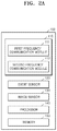
- FIGS. 2A and 2B are block diagrams illustrating the image transmitter 100 and the image receiver 200 configuring the surveillance system 1 according to an exemplary embodiment.
- the image transmitter 100 includes a communication module 110 , an event sensor 120 , an image sensor 130 , a processor 140 , and a memory 150 .
- the event sensor 120 may be also referred to as a motion detector or a motion detection camera.
- the event sensor 120 may be an optical, microwave, or acoustic sensor, and may detect changes in the optical, microwave, or acoustic field which are caused by a moving object.
- the event sensor 120 may include motion detection software.
- the communication module 110 performs communication with the image receiver 200 .
- the communication module 110 includes a first frequency communication module 111 and a second frequency communication module 112 .
- the first frequency communication module 111 may perform communication with a first frequency communication module 211 of the image receiver 200 .
- the second frequency communication module 112 may perform communication with a second frequency communication module 212 of the image receiver 200 .
- the first frequency communication module 111 and the second frequency communication module 112 respectively receive signals in different frequency bands.
- the first frequency communication module 111 may receive a signal in a high frequency band, and the second frequency communication module 112 may receive a signal in a low frequency band.
- the first frequency communication module 111 may receive a signal in a band of 2.4 GHz, and the second frequency communication module 112 may receive a signal in a band of 900 MHz.
- the first frequency communication module 111 may perform WiFi communication, and the second frequency communication module 112 may perform RF communication.
- the first frequency communication module 111 may perform WiFi communication with a WiFi communication module of the image receiver 200
- the second frequency communication module 112 may perform RF communication with an RF communication module of the image receiver 200 .
- the first frequency communication module 111 transmits a first frequency communication module connection request and a surveillance image to the image receiver 200 , and receives a first frequency communication module connection response from the image receiver 200 .
- a first frequency communication module connection request may be an access try to a port of the image receiver 200 designated by the image receiver 200 .
- a surveillance image may be a signal having weak signal strength.
- a surveillance image may be an outdoor surveillance image.
- a first frequency communication module connection response may represent that the imager transmitter 100 has been connected to the image receiver 200 .
- the second frequency communication module 112 transmits second frequency communication module notice information to the image receiver 200 , and receives first frequency communication module connection information from the image receiver 200 .
- the second frequency communication module notice information may be event information.
- the first frequency communication module connection information may be port information of the image receiver 200 .
- a first frequency communication module connection request may be an access try to a port of the image receiver 200 corresponding to port information included in first frequency communication module connection information.
- the event sensor 120 may detect an event occurring in a surveillance region. For example, the event sensor 120 may detect an event occurring in an outdoor surveillance region. The event sensor 120 may generate event information in response to an event.
- the image sensor 130 captures a surveillance region and obtains a surveillance image.
- the image sensor 130 may capture an outdoor surveillance region and obtain an outdoor surveillance image.
- the processor 140 controls operations of the communication module 110 , the event sensor 120 , the image sensor 130 , and the memory 150 .
- the processor 140 controls the first frequency communication module 111 to transmit a first frequency communication module connection request to the imager receiver 200 , and when receiving a first frequency communication module connection response from the image receiver 200 through the first frequency communication module 111 , the processor 140 controls the first frequency communication module 111 to transmit a surveillance image to the image receiver 200 .
- the memory 150 may store information transmitted/received through the communication module 110 , information generated by the event sensor 120 , an image obtained by the image sensor 130 , etc.
- the image transmitter 100 may be implemented as one physical apparatus and implemented as a plurality of physical apparatuses organically combined. For this purpose, a portion of a configuration included in the image transmitter 100 may be implemented or installed as one physical apparatus, and the rest of the configuration may be implemented or installed as the other physical apparatuses.
- the image transmitter 100 may be implemented in the first camera 11 or the second camera 12 .
- the image receiver 200 includes at least one of a communication module 210 , an external communication module 220 , a controller 230 , a database 240 , and a user interface 250 .
- the controller 230 may be also referred to as a processor, a microprocessor, or a central processing unit (CPU).
- the communication module 210 performs communication with the image transmitter 100 .
- the communication module 210 includes the first frequency communication module 211 and the second frequency communication module 212 .
- at least one of the first frequency communication modules 211 , the second frequency communication module 212 and the external communication module 220 may include any one or any combination of a digital modem, a radio frequency (RF) modem, a WiFi chip, and related software and/or firmware.
- RF radio frequency
- the first frequency communication module 211 may perform communication with the first frequency communication module 111 of the image transmitter 100 .
- the second frequency communication module 212 may perform communication with the second frequency communication module 112 of the image transmitter 100 .
- the first frequency communication module 211 and the second frequency communication module 212 respectively receive signals in different frequency bands.
- the first frequency communication module 211 may receive a signal in a high frequency band, and the second frequency communication module 212 may receive a signal in a low frequency band.
- the first frequency communication module 211 may receive a signal in a band of 2.4 GHz, and the second frequency communication module 212 may receive a signal in a band of 900 MHz.
- the first frequency communication module 211 may perform WiFi communication, and the second frequency communication module 212 may perform RF communication.
- the first frequency communication module 211 may perform WiFi communication with a WiFi communication module of the image transmitter 100
- the second frequency communication module 212 may perform RF communication with an RF communication module of the image transmitter 100 .
- the first frequency communication module 211 receives a surveillance image from the image transmitter 100 .
- the first frequency communication module 211 receives a first surveillance image from the first camera 11 and receives a second surveillance image from the second camera 12 .
- Signal strength of the first surveillance image is different from signal strength of the second surveillance image.
- signal strength of the first surveillance image may be stronger than signal strength of the second surveillance image.
- the first camera 11 may be located in an indoor space
- the second camera 12 may be located in an outdoor space. That is, the first frequency communication module 211 may receive an indoor surveillance image from the first camera 11 , and receive an outdoor surveillance image from the second camera 12 .
- the first frequency communication module 211 may include a low-noise amplifier.
- the first frequency communication module 211 may respectively receive surveillance images having different signal strengths depending on a gain value of the low-noise amplifier.
- the first frequency communication module 211 may receive a signal having strong signal strength when a gain value of the low-noise amplifier is a first gain value, and receive a signal having weak signal strength when a gain value of the low-noise amplifier is a second gain value.
- the first frequency communication module 211 may receive a first frequency communication module connection request from the image transmitter 100 .
- the first frequency communication module 211 may transmit a first frequency communication module connection response to the image transmitter 100 .
- the first frequency communication module 211 may transmit a first frequency communication module connection response to the image transmitter 100 .
- the second frequency communication module 212 receives second frequency communication module notice information from the image transmitter 100 .
- the second frequency communication module 212 may transmit first frequency communication module connection information to the image transmitter 100 .
- the external communication module 220 may perform communication with an apparatus excluding the image transmitter 100 .
- the external communication module 220 configuring the gateway 20 may perform communication with the management server 40 through the network 30 .
- the external communication module 220 implemented in the management server 40 may perform communication with the monitoring terminal 50 .
- the controller 230 controls operations of the communication module 210 , the external communication module 220 , the database 240 , and the user interface 250 .
- the controller 230 changes a gain value of the first frequency communication module 211 according to second frequency communication module notice information.
- the controller 230 may set a gain value of the first frequency communication module 211 to a first gain value in order to receive a first surveillance image having relatively strong signal strength, and change a gain value of the first frequency communication module 211 to a second gain value different from the first gain value in order to receive a second surveillance image in response to the second frequency communication module notice information.
- the first gain value may be a gain value of the low-noise amplifier of the first frequency communication module 211 for receiving an image having strong received strength
- the second gain value may be a gain value of the low-noise amplifier of the first frequency communication module 211 for receiving an image having weak received strength
- the controller 230 may change a gain value of the first frequency communication module 211 according to a user input requesting an image of the second camera 12 .
- the controller 230 may change the gain value of the first frequency communication module 211 to the first gain value again.
- the controller 230 may receive the second surveillance image from the second camera 12 .
- the controller 230 may set a gain value of the first frequency communication module 211 to the first gain value and receive the first surveillance image from the first camera 11 , and may receive the second surveillance image from the second camera 12 by changing the gain value of the first frequency communication module 211 to the second gain value only while the image receiver 200 is connected to the second camera 12 . Therefore, problems of a related art in which an outdoor surveillance image is classified as noise, connection of an indoor image signal is limited, or a signal bandwidth is limited, may be solved.
- the database 240 may store information transmitted/received through the communication module 210 .
- the database 240 may discriminate and store the first surveillance image and the second surveillance image.
- the user interface 250 may receive a user input.
- the user interface 250 may receive, for example, a user input requesting an image of the second camera 12 and/or a user input requesting transmission interruption of an image of the second camera 12 .
- the image receiver 200 may be implemented as one physical apparatus and implemented as a plurality of physical apparatuses organically combined. For this purpose, a portion of a configuration included in the image receiver 200 may be implemented or installed as one physical apparatus, and the rest of the configuration may be implemented or installed as the other physical apparatuses. In this case, each physical apparatus configuring the image receiver 200 may be implemented as a portion of at least one of the gateway 20 , the management server 40 , and the monitoring terminal 50 .
- FIGS. 3 and 4 are views illustrating a method of operating the surveillance system 1 according to an exemplary embodiment.
- the first frequency communication module 211 of the gateway 20 sets a gain value thereof to the first gain value under control of the controller 230 (operation S 101 ).
- the first camera 11 captures a first surveillance region (operation S 103 ) and transmits the first surveillance image to the gateway 20 (operation S 105 ).
- the first frequency communication module 211 of the gateway 20 receives the first surveillance image from the first camera 11 .
- the first camera 11 may be located in an indoor space.
- the first surveillance image may be an indoor surveillance image.
- the event sensor 120 of the second camera 12 detects an event occurring in a second surveillance region (operation S 107 ).
- the processor 140 of the second camera 12 controls an operation of the second frequency communication module 112 .
- the second camera 12 may be located in an outdoor space.
- the second frequency communication module 212 of the gateway 20 receives second frequency communication module notice information from the second frequency communication module 112 of the second camera 12 (operation S 109 ).
- the second frequency communication module notice information may be event information.
- the second frequency communication module 112 of the second camera 112 and the second frequency communication module 212 of the gateway 20 may perform RF communication.
- the first frequency communication module 211 of the gateway 20 changes a gain value thereof from the first gain value to the second gain value in response to the second frequency communication module notice information under control of the controller 230 (operation S 111 ).
- the controller 230 of the gateway 20 controls an operation of the second frequency communication module 212 .
- the second frequency communication module 212 of the gateway 20 transmits first frequency communication module connection information to the second frequency communication module 112 of the second camera 12 (operation S 113 ).
- the first frequency communication module connection information may be a port number designated by the gateway 20 .
- the first frequency communication module 111 of the second camera 12 transmits a first frequency communication module connection request to the first frequency communication module 211 of the gateway 20 according to the first frequency communication module connection information (operation S 115 ).
- the first frequency communication module connection request may be an access try to the port designated by the gateway 20 .
- the first frequency communication module 211 of the gateway 20 performs connection with the first communication module 111 of the second camera 12 in response to the first frequency communication module connection request (operation S 117 ).
- the first frequency communication module 211 of the gateway 20 When the first frequency communication module 211 of the gateway 20 is connected to the first frequency communication module 111 of the second camera 12 , the first frequency communication module 211 of the gateway 20 transmits a first frequency communication module connection response to the first frequency communication module 111 of the second camera 12 (operation S 119 ).
- the first frequency communication module connection response may represent that the second camera 12 has been connected to the port of the gateway 20 .
- the first frequency communication module 211 of the gateway 20 changes a gain value thereof from the second gain value to the first gain value under control of the controller 230 (operation S 121 ).
- the controller 230 of the gateway 20 may change a gain value of the first frequency communication module 211 from the second gain value to the first gain value after operation S 117 or S 119 , but is not limited thereto.
- the image sensor 130 of the second camera 12 captures a second surveillance region (operation S 123 ), and the first frequency communication module 111 transmits the second surveillance image to the gateway 20 (operation S 125 ).
- the first frequency communication module 211 of the gateway 20 may receive the second surveillance image from the first frequency communication module 111 of the second camera 12 .
- the first frequency communication module 111 of the second camera 12 and the first frequency communication module 211 of the gateway 20 may perform WiFi communication.
- the second surveillance image may be an outdoor surveillance image.
- Signal strength of the first surveillance image may be different from signal strength of the second surveillance image.
- signal strength of an indoor surveillance image may be stronger than signal strength of an outdoor surveillance image.
- the processor 140 of the second camera 12 may control an operation of the first frequency communication module 111 .
- the first frequency communication module 111 of the second camera 12 transmits a first frequency communication module separation request to the first frequency communication module 211 of the gateway 20 (operation S 127 ).
- the first frequency communication module 211 of the gateway 20 performs separation of the first frequency communication module 211 of the gateway 20 from the first frequency communication module 111 of the second camera 12 in response to the first frequency communication module separation request (operation S 129 ).
- the first frequency communication module 211 of the management server 40 sets a gain value thereof to the first gain value under control of the controller 230 (operation S 201 ).
- the first frequency communication module 211 of the management server 40 may receive the first surveillance image from the first camera 11 .
- the user interface 250 of the management server 40 may transmit the first surveillance image received through the first frequency communication module 211 to the monitoring terminal 50 .
- the monitoring terminal 50 receives a first user input (operation S 203 ).
- the first user input may be a user input requesting the second surveillance image of the second camera, not the first surveillance image.
- the user interface 250 of the management server 40 receives a second surveillance image request corresponding to the first user input from the monitoring terminal 50 (operation S 205 ).
- the first frequency communication module 211 of the management server 40 changes a gain value thereof from the first gain value to the second gain value in response to the second surveillance image request under control of the controller 230 (operation S 207 ).
- the second frequency communication module 212 of the management server 40 transmits first frequency communication module connection information to the second frequency communication module 112 of the second camera 12 (operation S 209 ).
- the first frequency communication module 111 of the second camera 12 transmits a first frequency communication module connection request to the first frequency communication module 211 of the management server 40 according to the first frequency communication module connection information (operation S 211 ).
- the first frequency communication module 211 of the management server 40 performs connection with the first frequency communication module 111 of the second camera 12 in response to the first frequency communication module connection request (operation S 213 ).
- the first frequency communication module 211 of the management server 40 When the first frequency communication module 211 of the management server 40 is connected to the first frequency communication module 111 of the second camera 12 , the first frequency communication module 211 of the management server 40 transmits a first frequency communication module connection response to the first frequency communication module 111 of the second camera 12 (operation S 215 ).
- the first frequency communication module 211 of the management server 40 changes a gain value thereof from the second gain value to the first gain value under control of the controller 230 (operation S 217 ).
- the controller 230 of the management server 40 may change a gain value of the first frequency communication module 211 from the second gain value to the first gain value after operation S 213 or S 215 , but is not limited thereto.
- the image sensor 130 of the second camera 12 captures a second surveillance region (operation S 219 ), and the first frequency communication module 111 transmits the second surveillance image to the management server 40 (operation S 221 ).
- the first frequency communication module 211 of the management server 40 may receive the second surveillance image from the first frequency communication module 111 of the second camera 12 .
- the user interface 250 of the management server 40 transmits the second surveillance image received through the first frequency communication module 211 to the monitoring terminal 50 in response to the second surveillance image request (operation S 223 ).
- the monitoring terminal 50 receives a second user input (operation S 225 ).
- the second user input may be a user input requesting transmission interruption of the second surveillance image of the second camera 12 .
- the user interface 250 of the management server 40 receives a transmission interruption request of the second surveillance image corresponding to the second user input from the monitoring terminal 50 (operation S 227 ).
- the first frequency communication module 211 of the management server 40 performs separation of the first frequency communication module 211 of the management server 40 from the first frequency communication module 111 of the second camera 12 in response to the transmission interruption request of the second surveillance image (operation S 229 ).
- the image receiver 200 located in an indoor space may receive outdoor surveillance images while effectively receiving indoor surveillance images by changing a gain value of a low-noise amplifier depending on circumstances, the surveillance system 1 which is more efficient and having improved performance may be provided to a user.
- an exemplary embodiment can be embodied as computer-readable code on a computer-readable recording medium.
- the computer-readable recording medium is any data storage device that can store data that can be thereafter read by a computer system. Examples of the computer-readable recording medium include read-only memory (ROM), random-access memory (RAM), CD-ROMs, magnetic tapes, floppy disks, and optical data storage devices.
- the computer-readable recording medium can also be distributed over network-coupled computer systems so that the computer-readable code is stored and executed in a distributed fashion.
- an exemplary embodiment may be written as a computer program transmitted over a computer-readable transmission medium, such as a carrier wave, and received and implemented in general-use or special-purpose digital computers that execute the programs.
- one or more units of the above-described apparatuses and devices can include circuitry, a processor, a microprocessor, etc., and may execute a computer program stored in a computer-readable medium
Abstract
Description
Claims (13)
Applications Claiming Priority (2)
| Application Number | Priority Date | Filing Date | Title |
|---|---|---|---|
| KR10-2017-0115912 | 2017-09-11 | ||
| KR1020170115912A KR102282472B1 (en) | 2017-09-11 | 2017-09-11 | Surveillance system and operation method thereof |
Publications (2)
| Publication Number | Publication Date |
|---|---|
| US20190082146A1 US20190082146A1 (en) | 2019-03-14 |
| US10659735B2 true US10659735B2 (en) | 2020-05-19 |
Family
ID=65631815
Family Applications (1)
| Application Number | Title | Priority Date | Filing Date |
|---|---|---|---|
| US15/919,870 Active 2038-04-28 US10659735B2 (en) | 2017-09-11 | 2018-03-13 | Surveillance system and method of operating surveillance system |
Country Status (3)
| Country | Link |
|---|---|
| US (1) | US10659735B2 (en) |
| KR (1) | KR102282472B1 (en) |
| CN (1) | CN109495717B (en) |
Families Citing this family (1)
| Publication number | Priority date | Publication date | Assignee | Title |
|---|---|---|---|---|
| WO2019177424A1 (en) | 2018-03-16 | 2019-09-19 | 주식회사 헬릭스미스 | Crude drug composition for preventing or treating respiratory diseases |
Citations (17)
| Publication number | Priority date | Publication date | Assignee | Title |
|---|---|---|---|---|
| JP2005269669A (en) | 2005-04-11 | 2005-09-29 | Hitachi Ltd | Digital radio receiver |
| KR100684028B1 (en) | 2005-10-17 | 2007-02-20 | 엘지전자 주식회사 | Audi0 signal processing method by receive signal strength indicator, and the mobile terminal therefor |
| US20090304345A1 (en) * | 2007-10-17 | 2009-12-10 | Shohji Ohtsubo | Video recording device, video recording method, video recording program, and integrated circuit |
| KR20120004242U (en) | 2010-12-06 | 2012-06-14 | 엘지에릭슨 주식회사 | Receiving gain adjustment apparatus in wireless lan |
| US8406706B2 (en) | 2010-05-20 | 2013-03-26 | Lg Electronics Inc. | Mobile terminal and method of controlling a driving voltage of a power amplifier therein |
| US20130102316A1 (en) * | 2011-10-24 | 2013-04-25 | Qualcomm Incorporated | Method and device for antenna searching with antenna selection |
| KR20130004052U (en) | 2011-12-26 | 2013-07-04 | 에릭슨 엘지 주식회사 | Apparatus for receiving gain controlling and mobile telecommunication system for the same |
| US8570373B2 (en) * | 2007-06-08 | 2013-10-29 | Cisco Technology, Inc. | Tracking an object utilizing location information associated with a wireless device |
| US20130343490A1 (en) * | 2012-06-20 | 2013-12-26 | Daniel S. Wertz | Synchronizing Receivers in a Signal Acquisition System |
| US20160261917A1 (en) * | 2015-03-03 | 2016-09-08 | Google Inc. | Systems and methods for broadcast audience interaction and participation |
| KR101689602B1 (en) | 2010-05-20 | 2016-12-26 | 엘지전자 주식회사 | Mobile terminal and method for controlling driving voltage of power amplifier |
| US20170230921A1 (en) * | 2014-08-25 | 2017-08-10 | Nec Space Technologies, Ltd. | Automatic gain control method and automatic gain control circuit |
| US20170318524A1 (en) * | 2016-04-28 | 2017-11-02 | Canon Kabushiki Kaisha | Communication apparatus, communication method, and storage medium |
| US20170374305A1 (en) * | 2015-03-06 | 2017-12-28 | Flir Systems, Inc. | Anomalous pixel detection |
| US20180349736A1 (en) * | 2017-05-30 | 2018-12-06 | Google Llc | Systems and Methods for Person Recognition Data Management |
| US10205913B2 (en) * | 2013-03-15 | 2019-02-12 | Master Lock Company Llc | Cameras and networked security systems and methods |
| US20190074601A1 (en) * | 2016-03-10 | 2019-03-07 | Samsung Electronics Co., Ltd. | Electronic device comprising antenna |
Family Cites Families (6)
| Publication number | Priority date | Publication date | Assignee | Title |
|---|---|---|---|---|
| US20030093805A1 (en) * | 2001-11-15 | 2003-05-15 | Gin J.M. Jack | Dual camera surveillance and control system |
| JP5264791B2 (en) * | 2010-01-25 | 2013-08-14 | ローレルバンクマシン株式会社 | Surveillance camera system |
| CN103338362B (en) * | 2013-07-26 | 2016-12-28 | 融创天下(上海)科技发展有限公司 | A kind of event-handling method based on video monitoring system and system |
| CN105338248B (en) * | 2015-11-20 | 2018-08-28 | 成都因纳伟盛科技股份有限公司 | Intelligent multiple target active tracing monitoring method and system |
| CN105407283B (en) * | 2015-11-20 | 2018-12-18 | 成都因纳伟盛科技股份有限公司 | A kind of multiple target initiative recognition tracing and monitoring method |
| CN106125621B (en) * | 2016-08-10 | 2018-10-30 | 深圳奥尼电子股份有限公司 | Safety defense monitoring system and security-protecting and monitoring method |
-
2017
- 2017-09-11 KR KR1020170115912A patent/KR102282472B1/en active IP Right Grant
-
2018
- 2018-03-13 US US15/919,870 patent/US10659735B2/en active Active
- 2018-07-13 CN CN201810768828.XA patent/CN109495717B/en active Active
Patent Citations (17)
| Publication number | Priority date | Publication date | Assignee | Title |
|---|---|---|---|---|
| JP2005269669A (en) | 2005-04-11 | 2005-09-29 | Hitachi Ltd | Digital radio receiver |
| KR100684028B1 (en) | 2005-10-17 | 2007-02-20 | 엘지전자 주식회사 | Audi0 signal processing method by receive signal strength indicator, and the mobile terminal therefor |
| US8570373B2 (en) * | 2007-06-08 | 2013-10-29 | Cisco Technology, Inc. | Tracking an object utilizing location information associated with a wireless device |
| US20090304345A1 (en) * | 2007-10-17 | 2009-12-10 | Shohji Ohtsubo | Video recording device, video recording method, video recording program, and integrated circuit |
| KR101689602B1 (en) | 2010-05-20 | 2016-12-26 | 엘지전자 주식회사 | Mobile terminal and method for controlling driving voltage of power amplifier |
| US8406706B2 (en) | 2010-05-20 | 2013-03-26 | Lg Electronics Inc. | Mobile terminal and method of controlling a driving voltage of a power amplifier therein |
| KR20120004242U (en) | 2010-12-06 | 2012-06-14 | 엘지에릭슨 주식회사 | Receiving gain adjustment apparatus in wireless lan |
| US20130102316A1 (en) * | 2011-10-24 | 2013-04-25 | Qualcomm Incorporated | Method and device for antenna searching with antenna selection |
| KR20130004052U (en) | 2011-12-26 | 2013-07-04 | 에릭슨 엘지 주식회사 | Apparatus for receiving gain controlling and mobile telecommunication system for the same |
| US20130343490A1 (en) * | 2012-06-20 | 2013-12-26 | Daniel S. Wertz | Synchronizing Receivers in a Signal Acquisition System |
| US10205913B2 (en) * | 2013-03-15 | 2019-02-12 | Master Lock Company Llc | Cameras and networked security systems and methods |
| US20170230921A1 (en) * | 2014-08-25 | 2017-08-10 | Nec Space Technologies, Ltd. | Automatic gain control method and automatic gain control circuit |
| US20160261917A1 (en) * | 2015-03-03 | 2016-09-08 | Google Inc. | Systems and methods for broadcast audience interaction and participation |
| US20170374305A1 (en) * | 2015-03-06 | 2017-12-28 | Flir Systems, Inc. | Anomalous pixel detection |
| US20190074601A1 (en) * | 2016-03-10 | 2019-03-07 | Samsung Electronics Co., Ltd. | Electronic device comprising antenna |
| US20170318524A1 (en) * | 2016-04-28 | 2017-11-02 | Canon Kabushiki Kaisha | Communication apparatus, communication method, and storage medium |
| US20180349736A1 (en) * | 2017-05-30 | 2018-12-06 | Google Llc | Systems and Methods for Person Recognition Data Management |
Also Published As
| Publication number | Publication date |
|---|---|
| CN109495717B (en) | 2021-07-20 |
| US20190082146A1 (en) | 2019-03-14 |
| KR102282472B1 (en) | 2021-07-27 |
| KR20190028956A (en) | 2019-03-20 |
| CN109495717A (en) | 2019-03-19 |
Similar Documents
| Publication | Publication Date | Title |
|---|---|---|
| WO2020253695A1 (en) | Smart home device access method and electronic device | |
| EP2922261B1 (en) | A method and technical equipment for short range data transmission | |
| US10140826B2 (en) | Surveillance system and method of controlling the same | |
| US11538316B2 (en) | Surveillance system and control method thereof | |
| WO2021238230A1 (en) | Smart home system and control method and device thereof | |
| US10805613B2 (en) | Systems and methods for optimization and testing of wireless devices | |
| KR101849670B1 (en) | System for managing internet of things device using network monitoring | |
| WO2019141058A1 (en) | Sensing indication method, terminal and network device | |
| US20120257051A1 (en) | Versatile wireless video and voice monitor | |
| KR20140112907A (en) | System, apparatus and method for connecting short distance communication | |
| CN111315035B (en) | WiFi network connection method and device | |
| JP6016383B2 (en) | COMMUNICATION DEVICE, COMMUNICATION DEVICE CONTROL METHOD, PROGRAM | |
| WO2021168757A1 (en) | Signal measurement method and apparatus, communication device and storage medium | |
| WO2022183456A1 (en) | Information transmission method and apparatus, communication device, and storage medium | |
| US10659735B2 (en) | Surveillance system and method of operating surveillance system | |
| US10225800B2 (en) | Portable device control method and device | |
| CN114125930B (en) | Method, device and system for switching access points | |
| US20180270763A1 (en) | Surveillance system and method of controlling the same | |
| US10542200B2 (en) | Surveillance camera system | |
| WO2022166461A1 (en) | Method, apparatus and system for determining device position | |
| WO2023272590A1 (en) | Terminal capability reporting method and apparatus, and storage medium | |
| JP2004128659A (en) | Wireless monitoring system | |
| WO2022120649A1 (en) | Access control method and apparatus, communication device, and medium | |
| WO2023226899A1 (en) | Csi obtaining method and device | |
| US20230117776A1 (en) | Method and device for detecting control channel and method for transmitting information |
Legal Events
| Date | Code | Title | Description |
|---|---|---|---|
| AS | Assignment |
Owner name: HANWHA TECHWIN CO., LTD., KOREA, REPUBLIC OF Free format text: ASSIGNMENT OF ASSIGNORS INTEREST;ASSIGNORS:JUNG, JAE HAG;PARK, JAE YEON;PARK, JAE WOO;REEL/FRAME:045190/0757 Effective date: 20180305 |
|
| FEPP | Fee payment procedure |
Free format text: ENTITY STATUS SET TO UNDISCOUNTED (ORIGINAL EVENT CODE: BIG.); ENTITY STATUS OF PATENT OWNER: LARGE ENTITY |
|
| STPP | Information on status: patent application and granting procedure in general |
Free format text: DOCKETED NEW CASE - READY FOR EXAMINATION |
|
| AS | Assignment |
Owner name: HANWHA AEROSPACE CO., LTD., KOREA, REPUBLIC OF Free format text: CHANGE OF NAME;ASSIGNOR:HANWHA TECHWIN CO., LTD;REEL/FRAME:046927/0019 Effective date: 20180401 |
|
| AS | Assignment |
Owner name: HANWHA AEROSPACE CO., LTD., KOREA, REPUBLIC OF Free format text: CORRECTIVE ASSIGNMENT TO CORRECT THE APPLICATION NUMBER 10/853,669. IN ADDITION PLEASE SEE EXHIBIT A PREVIOUSLY RECORDED ON REEL 046927 FRAME 0019. ASSIGNOR(S) HEREBY CONFIRMS THE CHANGE OF NAME;ASSIGNOR:HANWHA TECHWIN CO., LTD.;REEL/FRAME:048496/0596 Effective date: 20180401 |
|
| AS | Assignment |
Owner name: HANWHA TECHWIN CO., LTD., KOREA, REPUBLIC OF Free format text: ASSIGNMENT OF ASSIGNORS INTEREST;ASSIGNOR:HANWHA AEROSPACE CO., LTD.;REEL/FRAME:049013/0723 Effective date: 20190417 |
|
| STPP | Information on status: patent application and granting procedure in general |
Free format text: NON FINAL ACTION MAILED |
|
| STPP | Information on status: patent application and granting procedure in general |
Free format text: RESPONSE TO NON-FINAL OFFICE ACTION ENTERED AND FORWARDED TO EXAMINER |
|
| STPP | Information on status: patent application and granting procedure in general |
Free format text: NOTICE OF ALLOWANCE MAILED -- APPLICATION RECEIVED IN OFFICE OF PUBLICATIONS |
|
| STPP | Information on status: patent application and granting procedure in general |
Free format text: PUBLICATIONS -- ISSUE FEE PAYMENT VERIFIED |
|
| STCF | Information on status: patent grant |
Free format text: PATENTED CASE |
|
| AS | Assignment |
Owner name: HANWHA VISION CO., LTD., KOREA, REPUBLIC OF Free format text: CHANGE OF NAME;ASSIGNOR:HANWHA TECHWIN CO., LTD.;REEL/FRAME:064549/0075 Effective date: 20230228 |
|
| MAFP | Maintenance fee payment |
Free format text: PAYMENT OF MAINTENANCE FEE, 4TH YEAR, LARGE ENTITY (ORIGINAL EVENT CODE: M1551); ENTITY STATUS OF PATENT OWNER: LARGE ENTITY Year of fee payment: 4 |