US10649618B2 - System and method for creating visual representation of data based on generated glyphs - Google Patents
System and method for creating visual representation of data based on generated glyphs Download PDFInfo
- Publication number
- US10649618B2 US10649618B2 US15/980,526 US201815980526A US10649618B2 US 10649618 B2 US10649618 B2 US 10649618B2 US 201815980526 A US201815980526 A US 201815980526A US 10649618 B2 US10649618 B2 US 10649618B2
- Authority
- US
- United States
- Prior art keywords
- glyph
- generated
- data
- neural network
- glyphs
- Prior art date
- Legal status (The legal status is an assumption and is not a legal conclusion. Google has not performed a legal analysis and makes no representation as to the accuracy of the status listed.)
- Active
Links
Images


Classifications
-
- G—PHYSICS
- G06—COMPUTING; CALCULATING OR COUNTING
- G06T—IMAGE DATA PROCESSING OR GENERATION, IN GENERAL
- G06T11/00—2D [Two Dimensional] image generation
-
- G—PHYSICS
- G06—COMPUTING; CALCULATING OR COUNTING
- G06F—ELECTRIC DIGITAL DATA PROCESSING
- G06F18/00—Pattern recognition
- G06F18/20—Analysing
- G06F18/22—Matching criteria, e.g. proximity measures
-
- G—PHYSICS
- G06—COMPUTING; CALCULATING OR COUNTING
- G06F—ELECTRIC DIGITAL DATA PROCESSING
- G06F3/00—Input arrangements for transferring data to be processed into a form capable of being handled by the computer; Output arrangements for transferring data from processing unit to output unit, e.g. interface arrangements
- G06F3/01—Input arrangements or combined input and output arrangements for interaction between user and computer
- G06F3/048—Interaction techniques based on graphical user interfaces [GUI]
- G06F3/0481—Interaction techniques based on graphical user interfaces [GUI] based on specific properties of the displayed interaction object or a metaphor-based environment, e.g. interaction with desktop elements like windows or icons, or assisted by a cursor's changing behaviour or appearance
- G06F3/04817—Interaction techniques based on graphical user interfaces [GUI] based on specific properties of the displayed interaction object or a metaphor-based environment, e.g. interaction with desktop elements like windows or icons, or assisted by a cursor's changing behaviour or appearance using icons
-
- G06K9/6215—
-
- G—PHYSICS
- G06—COMPUTING; CALCULATING OR COUNTING
- G06N—COMPUTING ARRANGEMENTS BASED ON SPECIFIC COMPUTATIONAL MODELS
- G06N3/00—Computing arrangements based on biological models
- G06N3/02—Neural networks
- G06N3/04—Architecture, e.g. interconnection topology
- G06N3/045—Combinations of networks
-
- G—PHYSICS
- G06—COMPUTING; CALCULATING OR COUNTING
- G06T—IMAGE DATA PROCESSING OR GENERATION, IN GENERAL
- G06T11/00—2D [Two Dimensional] image generation
- G06T11/20—Drawing from basic elements, e.g. lines or circles
- G06T11/206—Drawing of charts or graphs
-
- G—PHYSICS
- G06—COMPUTING; CALCULATING OR COUNTING
- G06T—IMAGE DATA PROCESSING OR GENERATION, IN GENERAL
- G06T11/00—2D [Two Dimensional] image generation
- G06T11/60—Editing figures and text; Combining figures or text
-
- G—PHYSICS
- G06—COMPUTING; CALCULATING OR COUNTING
- G06V—IMAGE OR VIDEO RECOGNITION OR UNDERSTANDING
- G06V10/00—Arrangements for image or video recognition or understanding
- G06V10/70—Arrangements for image or video recognition or understanding using pattern recognition or machine learning
- G06V10/82—Arrangements for image or video recognition or understanding using pattern recognition or machine learning using neural networks
-
- G—PHYSICS
- G06—COMPUTING; CALCULATING OR COUNTING
- G06V—IMAGE OR VIDEO RECOGNITION OR UNDERSTANDING
- G06V30/00—Character recognition; Recognising digital ink; Document-oriented image-based pattern recognition
- G06V30/10—Character recognition
- G06V30/19—Recognition using electronic means
- G06V30/191—Design or setup of recognition systems or techniques; Extraction of features in feature space; Clustering techniques; Blind source separation
- G06V30/19173—Classification techniques
-
- G—PHYSICS
- G06—COMPUTING; CALCULATING OR COUNTING
- G06V—IMAGE OR VIDEO RECOGNITION OR UNDERSTANDING
- G06V30/00—Character recognition; Recognising digital ink; Document-oriented image-based pattern recognition
- G06V30/40—Document-oriented image-based pattern recognition
- G06V30/41—Analysis of document content
- G06V30/412—Layout analysis of documents structured with printed lines or input boxes, e.g. business forms or tables
-
- G—PHYSICS
- G06—COMPUTING; CALCULATING OR COUNTING
- G06F—ELECTRIC DIGITAL DATA PROCESSING
- G06F3/00—Input arrangements for transferring data to be processed into a form capable of being handled by the computer; Output arrangements for transferring data from processing unit to output unit, e.g. interface arrangements
- G06F3/01—Input arrangements or combined input and output arrangements for interaction between user and computer
- G06F3/048—Interaction techniques based on graphical user interfaces [GUI]
- G06F3/0481—Interaction techniques based on graphical user interfaces [GUI] based on specific properties of the displayed interaction object or a metaphor-based environment, e.g. interaction with desktop elements like windows or icons, or assisted by a cursor's changing behaviour or appearance
- G06F3/0482—Interaction with lists of selectable items, e.g. menus
-
- G—PHYSICS
- G06—COMPUTING; CALCULATING OR COUNTING
- G06N—COMPUTING ARRANGEMENTS BASED ON SPECIFIC COMPUTATIONAL MODELS
- G06N3/00—Computing arrangements based on biological models
- G06N3/02—Neural networks
- G06N3/08—Learning methods
-
- G—PHYSICS
- G06—COMPUTING; CALCULATING OR COUNTING
- G06N—COMPUTING ARRANGEMENTS BASED ON SPECIFIC COMPUTATIONAL MODELS
- G06N7/00—Computing arrangements based on specific mathematical models
- G06N7/01—Probabilistic graphical models, e.g. probabilistic networks
Definitions
- the present disclosure relates to data representation using generated, unique glyphs or icons, and more specifically, to systems and methods for automatically creating visual representation of data based using glyphs or icon generated by a machine based on an initial user input.
- Glyphs or Icons are increasingly being used to represent data or ideas in digital displays of data.
- glyphs or icons may be used in infographic charts commonly used to visually and expressively convey messages in data.
- the glyphs or icons in an infographic may be an integral component of infographics that are often required to both carry concise information and provide a compelling design, which can lead to a higher level of professionalism.
- Glyphs or icons are also commonly used in messaging or communications platforms to express messages or concepts. For example, emoji glyphs or icons are regularly used to express feelings or ideas simply with a minimal number of words or no words at all.
- aspects of the present application may relate to a method for creating a visual representation of data.
- the method may include receiving a user input to be represented by a glyph, generating, by a neural network, the glyph based on a vector extracted based on the received user input, linking an aspect of the generated glyph with an attribute of the data to be visually represented; and displaying the visual representation of the data created using the generated glyph to represent that linked aspect of the data.
- Additional aspects of the present application may relate to a non-transitory computer readable medium having stored therein a program for making a computer execute a method for creating a visual representation of data.
- the method may include receiving a user input to be represented by a glyph, generating, by a neural network, the glyph based on a vector extracted based on the received user input, linking an aspect of the generated glyph with an attribute of the data to be visually represented; and displaying the visual representation of the data created using the generated glyph to represent that linked aspect of the data.
- the method may include providing a user interface on a display, the user interface being configured to receive a user input to be represented by a glyph, the user input comprising one or more of a word, a short description, a user generated sketch, and a user generated stroke, generating, by a neural network, a potential glyph based on a vector extracted based on the received user input, displaying the generated potential glyph for selection.
- the computer apparatus may include means for receiving a user input to be represented by a glyph, means for generating, by a neural network, the glyph based on a vector extracted based on the received user input, means for linking an aspect of the generated glyph with an attribute of the data to be visually represented; and means for displaying the visual representation of the data created using the generated glyph to represent that linked aspect of the data.
- the computer apparatus may include means for providing a user interface on a display, the user interface being configured to receive a user input to be represented by a glyph, the user input comprising one or more of a word, a short description, a user generated sketch, and a user generated stroke, means for generating, by a neural network, a potential glyph based on a vector extracted based on the received user input, means for displaying the generated potential glyph for selection.
- FIG. 1 illustrates a flow chart of a process for generating glyphs or icons for an infographic in accordance with an example implementation of the present application.
- FIG. 2 illustrates a flow chart of another process for generating glyphs or icons for an infographic in accordance with an example implementation of the present application.
- FIG. 3 illustrates a user interface (UI) that may be used to control the system in accordance with an example implementation of the present application.
- UI user interface
- FIG. 4 illustrates a flow chart of a process for generating glyphs or icons in accordance with an example implementation of the present application.
- FIG. 5 illustrates a schematic representation of the glyph generation process illustrated in FIG. 4 in accordance with example implementations of the present application.
- FIG. 6 illustrates a grid of generated images of example glyph types experimentally produced by an example implementation of the present application.
- FIG. 7 illustrates an example computing environment with an example computer device suitable for use in some example implementations of the present application.
- Example implementations of the present application may include systems and methods to support a user in interactively creating, modifying, and guiding glyph authoring using neural networks.
- the system may include an image glyph generator to provide non-copyrighted glyph variations and an interface to support glyph creation as discussed in greater detail below.
- the example implementations may leverage a glyph image generator to illustrate a variety of candidate glyph images for a user to initialize and edit to create a desired glyph.
- a generated glyph can be unique, new and avoid issues of copyright.
- the generated glyph may be compared to known, copyrighted icons or glyphs and when a detected similarity exceeds a threshold, the generated glyph may be rejected and the generation model updated to create greater dissimilarity in subsequently generated glyphs.
- DCGANs Deep Convolution Generative Adversarial Network
- image may be used interchangeably to describe one or more of a photo, a video, a three-dimensional or 360° image recording, a drawing, painting, a sketch, a computer-generated image, or any other visual representation that may be produced, captured or may otherwise represent an item, event or occurrence in the real world.
- the “image” and “drawings” may be stored as a data file or other data structure on a computer readable medium including but not limited to a magnetic storage device, an optical storage device, a solid state storage device, an organic storage device or any other storage device that may be apparent to a person of ordinary skill in the art.
- the terms “glyph”, “icon”, or “drawing” may be used interchangeably to describe any graphic conceptual representation of a word, phrase, object, place, person, or thing that may be apparent to a person of ordinary skill in the art.
- the “glyph”, “icon”, or “drawing” may be stored as a data file or other data structure on a computer readable medium including but not limited to a magnetic storage device, an optical storage device, a solid state storage device, an organic storage device or any other storage device that may be apparent to a person of ordinary skill in the art.
- the computer readable medium may include a local storage device, a cloud-based storage device, a remotely located server, or any other storage device that may be apparent to a person of ordinary skill in the art.
- FIG. 1 illustrates a flow chart of a process 100 for generating glyphs or icons for an infographic in accordance with an example implementation of the present application.
- the process 100 may be performed by a computing device in a computing environment such as example computing device 705 of the example computing environment 700 illustrated in FIG. 7 discussed below. Though the elements of process 100 may be illustrated in a particular sequence, example implementations are not limited to the particular sequence illustrated. Example implementations may include actions being ordered into a different sequence as may be apparent to a person of ordinary skill in the art or actions may be performed in parallel or dynamically, without departing from the scope of the present application.
- user input to be represented by a generated glyph is received by the system at 105 .
- the user input may include input a short text description 110 , such as “apple”, or draw a sketch or a few strokes 115 , or both.
- the user input may be provided by a user using a user interface (UI) such as UI 300 illustrated in FIG. 3 discussed below.
- UI user interface
- the system may take the user input (e.g., short text description 110 and sketch or a few strokes 115 ) to generate a range of glyphs 125 using deep learning or machine processes, based on the text description 110 and/or the sketch/strokes 115 provide.
- these glyphs 125 may optionally be further edited by a user and the system may repeat 105 and 120 to generate new sets of glyphs accordingly.
- the data 135 to be represented may optionally be used to affect the glyph generation at 120 .
- certain attributes of the data 135 such as the variance or variability, may affect the number of different types of glyphs generated or the degree of variation between different glyphs generated. Additional aspects of the glyph generation are discussed in greater detail below with respect to sub-process 400 of FIG. 4 below.
- the user input 105 may be used to link the drawing properties of the glyphs to attributes of the data 135 at 140 to adjust the appearances of the glyphs for each set of entry in the dataset 135 .
- a UI such as UI 300 of FIG. 3 may be used to specify attributes of the data (e.g., value, range, category, etc.) and drawing properties (e.g., stroke/line color, fill opacity, glyph type, fill color, fill pattern, stroke/line width, stroke/line pattern, etc.) to be linked in the completed infographic.
- the user input 105 and the data 135 may optionally be used to specify chart layout parameters at 130 to be used to generate the infographic.
- a UI such as UI 300 of FIG. 3 may be used to select different chart layouts that visualize a row dataset, and further attach the generated glyphs to the basic chart layout.
- the glyphs 125 produced by the glyph generation 120 , the attribute linking 140 and, optionally, the chart layout parameters 130 may be used at 145 to generate an infographic. Afterwards, a user can add annotations and perform post-editing on the chart, thus producing a final compelling infographic that is empowered by the generated glyphs.
- the produced infographic may be displayed, stored, printed, posted to social media or otherwise used in any manner that may be apparent to a person of ordinary skill in the art.
- the process 100 may end after the infographic is generated at 145 .
- FIG. 2 illustrates a flow chart of another process 200 for generating glyphs or icons for an infographic in accordance with an example implementation of the present application.
- Some aspects of the process 200 may be similar to the process 100 discussed above with respect to FIG. 1 as such redundant discussion may be omitted herein.
- the process 200 may be performed by a computing device in a computing environment such as example computing device 705 of the example computing environment 700 illustrated in FIG. 7 discussed below. Though the elements of process 200 may be illustrated in a particular sequence, example implementations are not limited to the particular sequence illustrated. Example implementations may include actions being ordered into a different sequence as may be apparent to a person of ordinary skill in the art or actions may be performed in parallel or dynamically, without departing from the scope of the present application.
- user input to be represented by a generated glyph is received by the system at 205 .
- the user input may include input a short text description 210 , such as “apple”, or draw a sketch or a few strokes 215 , or both.
- the user input may be provided by a user using a user interface (UI) such as UI 300 illustrated in FIG. 3 discussed below.
- UI user interface
- the system may take the user input (e.g., short text description 110 and sketch or a few strokes 115 ) to generate a range of glyphs 225 using deep learning or machine processes, based on the text description 210 and/or the sketch/strokes 215 provide.
- these glyphs 125 may optionally be further edited by a user and the system may repeat 105 and 120 to generate new sets of glyphs accordingly.
- the data 235 to be represented may optionally be used to affect the glyph generation at 220 .
- certain attributes of the data 235 such as the variance or variability, may affect the number of different types of glyphs generated or the degree of variation between different glyphs generated. Additional aspects of the glyph generation are discussed in greater detail below with respect to sub-process 400 of FIG. 4 below.
- the produced glyphs 225 in combination with the user input 205 and the data 235 may be used to specify chart layout parameters at 230 to be used to generate the infographic.
- a UI such as UI 300 of FIG. 3 may be used to select different chart layouts that visualize a row dataset, and further attach the generated glyphs to the basic chart layout.
- the user input 205 may be used to link the drawing properties of the generated glyphs 225 to attributes of the data 235 at 240 to adjust the appearances of the glyphs for each set or entry in the dataset 235 .
- a UI such as UI 300 of FIG. 3 may be used to specify attributes of the data (e.g., value, range, category, etc.) and drawing properties (e.g., stroke/line color, fill opacity, glyph type, fill color, fill pattern, stroke/line width, stroke/line pattern, etc.) to be linked in the completed infographic.
- the attribute linking 240 , the glyphs 225 , the linked attributes and the chart layout parameters may be used at 245 to generate an infographic.
- a user can add annotations and perform post-editing on the chart, thus producing a final compelling infographic that is empowered by the generated glyphs.
- the produced infographic may be displayed, stored, printed, posted to social media or otherwise used in any manner that may be apparent to a person of ordinary skill in the art.
- the process 200 may end after the infographic is generated at 245 .
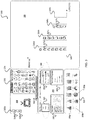
- FIG. 3 illustrates a user interface (UI) 300 that may be used to control the system in accordance with an example implementation of the present application.
- the UI 300 may be displayed on a display device including, but not limited to, a computer monitor, TV, touchscreen display of a mobile device, a laptop display screen, or any other display device that may be apparent to a person of ordinary skill in the art.
- UI 300 includes contains four main panels, including a main canvas 305 , a glyph authoring panel 310 , a data binding panel 315 , and a chart layout panel 320 .
- a user can either input text (e.g., “TV”) describing an object or draw a quick sketch of that object, using the three buttons 328 a - 328 c on the left of the panel.
- the glyph authoring panel 310 may be implemented as a touch screen display to allow a user to drawing directly into the glyph authoring panel 310 , or may be configured to receive input from a user input device such as an electronic sketch panel or other device to allow a user's strokes to be captured and recognized.
- the system may generate a list of glyphs with variations based on the user's input, which is shown in the recommendation section 330 of the glyph authoring panel 310 .
- a user can select glyphs from that recommendation section 330 to apply, and, in some example implementations, add or remove strokes to refine the sketch using buttons 328 a and 328 b .
- the system may generate a new list of glyphs and update the recommendation section 330 . This may form an iterative and interactive process of authoring glyphs.
- the UI 300 may also include a slider 360 to allow a user to adjust the level of variety of glyphs to generate more or less consistent glyphs. For example, a user may want to generate a plurality of similar glyphs to represent data having only slight differences, or a user may want to generate a plurality of widely varying glyphs to represent widely varying data.
- the UI 300 may also include browsing history of generated glyphs displayed in the history section 335 on the right of the panel, which allows a user to go back and choose previously created glyphs. This may serves as a customized and dynamic glyph library for the user.
- the glyph authoring panel 310 may facilitate or assist users with glyph curation and authoring, especially for general audiences who do not have good artistic skills. For example, if a user is really not good at drawing, they can just input a word (e.g., “TV” in FIG. 3 ); and if a user wants to take some control but is not very confident, they can draw some initial strokes. In both cases, the system offers a wide selection of glyphs to lower the barriers of making professional-like drawings. Also, at any time, a user may be able to edit the generated results if they are not satisfied.
- the glyph authoring panel 310 may be provided as a separate UI and may be independent from an infographic generation UI, such as the UI 300 illustrated in FIG. 3 .
- the glyph authoring panel 310 may be implemented as part of messaging or communication platform or any other platform requiring authoring or creation of custom glyphs or icons.
- the data binding panel 325 may allow a user to choose which drawing properties 350 (e.g., fill color, stroke width, etc.) should be encoded or linked to which data attributes 340 from a raw dataset that is loaded at the beginning. For example, a user may wish to set the fill color of a glyph to indicate different Revenue ranges.
- the connected drawing properties and data attributes are displayed on the top part (emphasized by oval 365 ) of the data binding panel 325 .
- a small data table 345 may provide a preview of the dataset and its attributes.
- the data binding panel 325 also shows a list of available drawing properties 355 (e.g., the drawing properties not yet bound with data attributes).
- the data binding panel 325 may allow a user to create the data bindings with simple drag-and-drop interaction (e.g., dragging an attribute label in the data table to an available drawing property or vice versa).
- the chart layout panel 320 may display a basic chart that is driven by the data on the main canvas 305 , just like a spreadsheet application or program. A user then can attach the glyphs to the chart elements to increase the expressiveness and attractiveness of the graphics. For example, in FIG.
- a user may selects the bar chart layout 370 a and attaches three different types of “TV” glyphs 327 a , 327 b , 372 c to different bars 326 a , 326 b , 326 c in the chart 325 in the main canvas.
- One empty bar 326 d that is originally generated by the bar chart layout is left to add another “TV” glyph.
- FIG. 4 illustrates a flow chart of a process 400 for generating glyphs or icons in accordance with an example implementation of the present application.
- the process 400 may be performed as part of generating an infographic using a process such as process 100 or process 200 illustrated in FIGS. 1 and 2 discussed above.
- the process 400 may also be performed independently of an infographic generating process.
- the process 400 may be performed as part of a spreadsheet or data manipulation program, a presentation development program, a messaging or communications platform or as part of a social media product or any other application that might be apparent to a person of ordinary skill in the art.
- the process 400 may be performed by a computing device in a computing environment such as example computing device 705 of the example computing environment 700 illustrated in FIG. 7 discussed below. Though the elements of process 400 may be illustrated in a particular sequence, example implementations are not limited to the particular sequence illustrated. Example implementations may include actions being ordered into a different sequence as may be apparent to a person of ordinary skill in the art or actions may be performed in parallel or dynamically, without departing from the scope of the present application.
- the process 400 may involve the use of a Generative Adversarial Networks (GANs), such as GANS 515 and 520 illustrated in FIG. 5 .
- GANs Generative Adversarial Networks
- the description of the process 400 may reference elements of the schematic representation 500 of FIG. 5 discussed in greater detail below.
- a user input is received at 405 defining an aspect on which the glyph or icon is to be based.
- the step 405 may be analogous to the steps 105 and 205 discussed above with respect to processes 100 and 200 discussed above.
- the user input may be a word or short textual description (e.g., “apple”), a simple sketch, or a few simple strokes provided through a UI.
- a prior context vector (e.g., condition vector 510 illustrated in FIG. 5 discussed below) may be generated based on the received user input at 410 .
- the prior context vector may be generated or extracted from one or more known graphical representations associated with the received word or textual description.
- the prior context vector may be generated or extracted from the simple sketch or strokes provided by the user input.
- the prior context vector may be combined with randomly generated vector (e.g., random vector 505 illustrated in FIG. 5 discussed below) by a first neural network (1 st NN) at 415 .
- the first neural network may be considered a generator neural network (e.g., generator NN 515 of FIG. 5 ) that has been trained with pre-existing glyphs to generate potential glyphs that are attempted to be indistinguishable from the pre-existing glyphs (e.g., potential glyphs having a high similarity to the pre-existing glyphs).
- a variability slider (e.g., slider 360 of UI 300 ) may control the weighting factors applied to the randomly generated vector and the prior context vector during the combining to control variability between the potential glyph generated and the prior context vector. By weighting the random vector more strongly, more variable potential glyphs may be produced.
- the potential glyph is provided to a second neural network (2 nd NN) tasked with comparing the potential glyph with one or more preexisting images, drawings, glyphs, or icons selected based on the received user input at 420 .
- the second neural network may be trained with pairs of glyphs or icons and other images or drawings that have been tagged as either similar or not similar.
- a determination is made whether the second neural network could distinguish the potential glyph from the one or more preexisting images, drawings, glyphs, or icons. If the second neural network can distinguish the potential glyph from the one or more preexisting images, drawings, glyphs or icons (Yes at 425 ), the process 400 may return to 415 and the first neural network may repeat step 415 to generate a new potential glyph.
- the process 400 may continue to step 430 and the potential glyph to a user for selection. Once the potential glyph is submitted to the user, the process 400 may end in some example implementations. In other example implementations, the process 400 may return to 410 to generate a new prior context vector based on the received user input and the process 400 may be repeated to generate additional potential glyphs.
- the generated glyph may be compared, by the discriminator neural network 520 (2 nd NN) or by another neural network, to known copyrighted icons or glyphs and when a detected similarity exceeds a threshold, the generated glyph may be rejected and the generator model updated to create greater dissimilarity in subsequently generated glyphs.
- the threshold may be defined by a user, a manager, a service provider, or may be dynamically determined by the system.
- FIG. 5 illustrates a schematic representation 500 of the glyph generation process described above with respect to FIG. 4 in accordance with example implementations of the present application.
- the glyph generation process may use two or more Generative adversarial networks (GANs) 515 , 520 .
- GANs Generative adversarial networks
- These GANs are illustrated in FIG. 5 are a class of machine learning methods that are implemented by the two neural networks, one as a generator 515 and the other as a discriminator 520 , competing with each other in a zero-sum game framework.
- the generator network 515 may be trained to generate realistic glyphs or icons 525 that the discriminator network 520 could not differentiate pre-existing images, drawings, or glyphs.
- the discriminator network 520 may be trained to differentiate between fake glyphs generated by the generator network and pre-existing images, drawings, or glyphs in training data.
- the network architecture of the networks 515 , 520 may be extended to multiple layers and replaced with strided convolutions, namely, Deep Convolution Generative Adversarial Networks (DCGANs).
- DCGANs Deep Convolution Generative Adversarial Networks
- GANs can be initiated by combining a random vector 505 to keep the uniqueness of the generated glyphs and prior context condition vector 510 (e.g., text or visual information) to force the generated glyphs to be aligned with the specified context.
- Example implementations of the present application are not limited to the GANs 515 , 520 illustrated in FIG. 5 or the process 400 illustrated in FIG. 4 and other neural networking architectures and processes for generating a glyph or icon based on a received user input that may be apparent to a person of ordinary skill in the art may be used in example implementations of the present application.
- FIG. 6 illustrates a grid 600 of generated images of six example glyph types, (i.e., spoon 605 , mushroom 615 , laptop 630 , TV 610 , apple 620 , hand 625 ) experimentally produced by an example implementation of the present application.
- six example glyph types i.e., spoon 605 , mushroom 615 , laptop 630 , TV 610 , apple 620 , hand 625
- 22,000 28 ⁇ 28 training images of each glyph type were used to learn a unified model of all glyph types.
- the grid of the generated glyph images may exhibit considerable variation that provides users with more options.
- the generated glyph images are similar enough the style of the training data so that they may form a set of glyphs with matching style.
- the style may be data-driven and hence can be changed by using a different style of training data, (e.g., watercolor painting, photo realistic sketch, doodles, stick figure, etc.).
- a user's interaction with a glyph generation system e.g., prior selections, prior modifications, prior annotations
- additional training data e.g., “re-training” or “supplemental training”
- detecting commonalities or common aspects of glyphs a user or group of uses has selected, or introduced through manual modification or annotation may cause the system to attempt to produce additional glyphs with the detected commonalities or common aspects.
- the generated images in the experimental results are visually similar to the glyph images that were drawn by humans but are machine generated by the system with only minimal user inputs.
- FIG. 7 illustrates an example computing environment 700 with an example computer device 705 suitable for use in some example implementations.
- Computing device 705 in computing environment 700 can include one or more processing units, cores, or processors 710 , memory 715 (e.g., RAM, ROM, and/or the like), internal storage 720 (e.g., magnetic, optical, solid state storage, and/or organic), and/or I/O interface 725 , any of which can be coupled on a communication mechanism or bus 730 for communicating information or embedded in the computing device 705 .
- memory 715 e.g., RAM, ROM, and/or the like
- internal storage 720 e.g., magnetic, optical, solid state storage, and/or organic
- I/O interface 725 any of which can be coupled on a communication mechanism or bus 730 for communicating information or embedded in the computing device 705 .
- Computing device 705 can be communicatively coupled to input/interface 735 and output device/interface 740 .
- Either one or both of input/interface 735 and output device/interface 740 can be a wired or wireless interface and can be detachable.
- Input/interface 735 may include any device, component, sensor, or interface, physical or virtual, which can be used to provide input (e.g., buttons, touch-screen interface, keyboard, a pointing/cursor control, microphone, camera, braille, motion sensor, optical reader, and/or the like).
- Output device/interface 740 may include a display, television, monitor, printer, speaker, braille, or the like.
- input/interface 735 e.g., user interface
- output device/interface 740 can be embedded with, or physically coupled to, the computing device 705 .
- other computing devices may function as, or provide the functions of, an input/interface 735 and output device/interface 740 for a computing device 705 .
- These elements may include, but are not limited to, well-known AR hardware inputs so as to permit a user to interact with an AR environment.
- Examples of computing device 705 may include, but are not limited to, highly mobile devices (e.g., smartphones, devices in vehicles and other machines, devices carried by humans and animals, and the like), mobile devices (e.g., tablets, notebooks, laptops, personal computers, portable televisions, radios, and the like), and devices not designed for mobility (e.g., desktop computers, server devices, other computers, information kiosks, televisions with one or more processors embedded therein and/or coupled thereto, radios, and the like).
- highly mobile devices e.g., smartphones, devices in vehicles and other machines, devices carried by humans and animals, and the like
- mobile devices e.g., tablets, notebooks, laptops, personal computers, portable televisions, radios, and the like
- devices not designed for mobility e.g., desktop computers, server devices, other computers, information kiosks, televisions with one or more processors embedded therein and/or coupled thereto, radios, and the like.
- Computing device 705 can be communicatively coupled (e.g., via I/O interface 725 ) to external storage 745 and network 750 for communicating with any number of networked components, devices, and systems, including one or more computing devices of the same or different configuration.
- Computing device 705 or any connected computing device can be functioning as, providing services of, or referred to as a server, client, thin server, general machine, special-purpose machine, or another label.
- I/O interface 725 can include, but is not limited to, wired and/or wireless interfaces using any communication or I/O protocols or standards (e.g., Ethernet, 802.11xs, Universal System Bus, WiMAX, modem, a cellular network protocol, and the like) for communicating information to and/or from at least all the connected components, devices, and network in computing environment 700 .
- Network 750 can be any network or combination of networks (e.g., the Internet, local area network, wide area network, a telephonic network, a cellular network, satellite network, and the like).
- Computing device 705 can use and/or communicate using computer-usable or computer-readable media, including transitory media and non-transitory media.
- Transitory media includes transmission media (e.g., metal cables, fiber optics), signals, carrier waves, and the like.
- Non-transitory media includes magnetic media (e.g., disks and tapes), optical media (e.g., CD ROM, digital video disks, Blu-ray disks), solid state media (e.g., RAM, ROM, flash memory, solid-state storage), and other non-volatile storage or memory.
- Computing device 705 can be used to implement techniques, methods, applications, processes, or computer-executable instructions in some example computing environments.
- Computer-executable instructions can be retrieved from transitory media, and stored on and retrieved from non-transitory media.
- the executable instructions can originate from one or more of any programming, scripting, and machine languages (e.g., C, C++, C #, Java, Visual Basic, Python, Perl, JavaScript, and others).
- Processor(s) 710 can execute under any operating system (OS) (not shown), in a native or virtual environment.
- OS operating system
- One or more applications can be deployed that include logic unit 755 , application programming interface (API) unit 760 , input unit 765 , output unit 770 , glyph generating unit 775 , aspect linking unit 780 , chart type determining unit 785 , visual representation creating unit 790 , and inter-unit communication mechanism 795 for the different units to communicate with each other, with the OS, and with other applications (not shown).
- OS operating system
- API application programming interface
- the glyph generating unit 775 , aspect linking unit 780 , chart type determining unit 785 , and visual representation creating unit 790 may implement one or more processes shown in FIGS. 1, 2, and 4 .
- the described units and elements can be varied in design, function, configuration, or implementation and are not limited to the descriptions provided.
- API unit 760 when information or an execution instruction is received by API unit 760 , it may be communicated to one or more other units (e.g., glyph generating unit 775 , aspect linking unit 780 , chart type determining unit 785 , and visual representation creating unit 790 ).
- the glyph generating unit 775 may generate a glyph based on a received user input and provide the glyph to the aspect linking unit 780 .
- the aspect linking unit 780 may link one or more aspects of the received glyph to attributes of data to be displayed in a visual representation.
- the chart type determining unit 785 may determine a type of chart to be displayed based on a determination based on a received user input or based on additional attributes of data to be displayed.
- the visual representation creating unit may create a chart or other visual representation based on the determined chart type and the generated glyph linked to an attribute of the data to be displayed.
- the logic unit 755 may be configured to control the information flow among the units and direct the services provided by API unit 760 , input unit 765 , glyph generating unit 775 , aspect linking unit 780 , chart type determining unit 785 , and visual representation creating unit 790 in some example implementations described above.
- the flow of one or more processes or implementations may be controlled by logic unit 755 alone or in conjunction with API unit 760 .
Abstract
Description
Claims (21)
Priority Applications (3)
| Application Number | Priority Date | Filing Date | Title |
|---|---|---|---|
| US15/980,526 US10649618B2 (en) | 2018-05-15 | 2018-05-15 | System and method for creating visual representation of data based on generated glyphs |
| CN201910175829.8A CN110489024A (en) | 2018-05-15 | 2019-03-08 | The system and method for the visual representation of creation data are accorded with based on pictograph generated |
| JP2019078565A JP7318290B2 (en) | 2018-05-15 | 2019-04-17 | Methods, programs and computer devices for generating glyphs and creating visual representations of data based on the generated glyphs |
Applications Claiming Priority (1)
| Application Number | Priority Date | Filing Date | Title |
|---|---|---|---|
| US15/980,526 US10649618B2 (en) | 2018-05-15 | 2018-05-15 | System and method for creating visual representation of data based on generated glyphs |
Publications (2)
| Publication Number | Publication Date |
|---|---|
| US20190354261A1 US20190354261A1 (en) | 2019-11-21 |
| US10649618B2 true US10649618B2 (en) | 2020-05-12 |
Family
ID=68533716
Family Applications (1)
| Application Number | Title | Priority Date | Filing Date |
|---|---|---|---|
| US15/980,526 Active US10649618B2 (en) | 2018-05-15 | 2018-05-15 | System and method for creating visual representation of data based on generated glyphs |
Country Status (3)
| Country | Link |
|---|---|
| US (1) | US10649618B2 (en) |
| JP (1) | JP7318290B2 (en) |
| CN (1) | CN110489024A (en) |
Families Citing this family (6)
| Publication number | Priority date | Publication date | Assignee | Title |
|---|---|---|---|---|
| EP3857500B1 (en) | 2019-07-01 | 2023-06-07 | Digimarc Corporation | Watermarking arrangements permitting vector graphics editing |
| US11727192B2 (en) * | 2021-03-03 | 2023-08-15 | Adobe Inc. | Font customization based on stroke properties |
| US11776168B2 (en) * | 2021-03-31 | 2023-10-03 | Adobe Inc. | Extracting textures from text based images |
| CN113468624B (en) * | 2021-07-26 | 2024-02-27 | 浙江大学 | Analysis method and system for round icon based on instance design |
| CN113515675B (en) * | 2021-07-26 | 2023-06-06 | 中国人民解放军国防科技大学 | Conflict game analysis visualization method, device and equipment based on graph model |
| JP7106085B1 (en) * | 2022-01-29 | 2022-07-26 | 株式会社ルビス | Design generation system and design generation method |
Family Cites Families (9)
| Publication number | Priority date | Publication date | Assignee | Title |
|---|---|---|---|---|
| US7725825B2 (en) * | 2004-09-28 | 2010-05-25 | Ricoh Company, Ltd. | Techniques for decoding and reconstructing media objects from a still visual representation |
| US8018470B2 (en) * | 2006-03-28 | 2011-09-13 | Microsoft Corporation | Vector based object property variations |
| US8032469B2 (en) * | 2008-05-06 | 2011-10-04 | Microsoft Corporation | Recommending similar content identified with a neural network |
| US20120102419A1 (en) * | 2010-10-22 | 2012-04-26 | Microsoft Corporation | Representing data through a graphical object |
| US8416261B1 (en) * | 2012-06-21 | 2013-04-09 | Google Inc. | Clock objects having visual graphical indicators with interactive time shifting |
| US10809865B2 (en) * | 2013-01-15 | 2020-10-20 | Microsoft Technology Licensing, Llc | Engaging presentation through freeform sketching |
| US9443331B2 (en) * | 2013-06-06 | 2016-09-13 | Microsoft Technology Licensing, Llc | Input object for routing input for visual elements |
| AU2014100876A4 (en) * | 2013-08-06 | 2014-09-04 | New Bis Safe Luxco S.À R.L | Methods, apparatus and systems for data visualisation and related applications |
| US10916001B2 (en) * | 2016-11-28 | 2021-02-09 | Adobe Inc. | Facilitating sketch to painting transformations |
-
2018
- 2018-05-15 US US15/980,526 patent/US10649618B2/en active Active
-
2019
- 2019-03-08 CN CN201910175829.8A patent/CN110489024A/en active Pending
- 2019-04-17 JP JP2019078565A patent/JP7318290B2/en active Active
Non-Patent Citations (8)
| Title |
|---|
| Goodfellow, I.J., et al., "Generative Adversarial Nets", (NIPS 2014), pp. 1-9. |
| Ha et al., "A Neural Representation of Sketch Drawings", May 2017. (Year: 2017). * |
| Ha, D., et al., "A Neural Representation of Sketch Drawings", Apr. 16, 2017, pp. 1-20. |
| Haroz, S., et al, "ISOTYPE Visualization-Working Memory, Performance, and Engagement with Pictographs", In Proceeding of the 33rd Annual ACM Conference on Human Factors in Computing Systems, CHI'15, Seoul, Republic of Korea, Apr. 18-23, 2015 (10 pages). |
| Kim, N.W., et al., Data-Driven Guides: Supporting Expressive Design for Information Graphics. IEEE Transactions on Visualization and Computer Graphics Forum, 2017 (10 pages). |
| Radford, A., et al., "Unsupervised Representation Learning With Deep Convolutional General Adversarial Networks", Nov. 19, 2015, pp. 1-15. |
| Satyanarayan A., et al., "Lyra: An Interactive Visualization Design Environment". Computer Graphics Form, vol. 33 (2014), No. 3 (10 pages). |
| Setlur, V., et al., "Automatic Generation of Semantic Icon Encodings for Visualizations". Session: Designing and Understanding Visualizations, CHI' 2014, One of a CHInd, Apr. 26-May 1, 2014, Toronto, ON, Canada, pp. 541-550. |
Also Published As
| Publication number | Publication date |
|---|---|
| JP2019200782A (en) | 2019-11-21 |
| JP7318290B2 (en) | 2023-08-01 |
| CN110489024A (en) | 2019-11-22 |
| US20190354261A1 (en) | 2019-11-21 |
Similar Documents
| Publication | Publication Date | Title |
|---|---|---|
| US10649618B2 (en) | System and method for creating visual representation of data based on generated glyphs | |
| US20150277686A1 (en) | Systems and Methods for the Real-Time Modification of Videos and Images Within a Social Network Format | |
| US11847409B2 (en) | Management of presentation content including interjecting live feeds into presentation content | |
| US10579737B2 (en) | Natural language image editing annotation framework | |
| US20180356967A1 (en) | Facilitating automatic generation of customizable storyboards | |
| US11604641B2 (en) | Methods and systems for resolving user interface features, and related applications | |
| US20150121232A1 (en) | Systems and Methods for Creating and Displaying Multi-Slide Presentations | |
| US20150121189A1 (en) | Systems and Methods for Creating and Displaying Multi-Slide Presentations | |
| US20180342084A1 (en) | Method and apparatus for automatic line drawing coloring and graphical user interface thereof | |
| US9256968B2 (en) | Method for modeling using sketches | |
| TW201237764A (en) | Method, apparatus, and computer program product for overlapped handwriting | |
| US9372609B2 (en) | Asset-based animation timelines | |
| WO2019199480A1 (en) | Automated image scale adjustment based upon document and image context | |
| US10685470B2 (en) | Generating and providing composition effect tutorials for creating and editing digital content | |
| US20190243532A1 (en) | Information processing device and non-transitory computer readable medium | |
| US11829712B2 (en) | Management of presentation content including generation and rendering of a transparent glassboard representation | |
| CN109493401B (en) | PowerPoint generation method, device and electronic equipment | |
| Morson | Learn design for iOS development | |
| US11961261B2 (en) | AI-based aesthetical image modification | |
| Jiang et al. | Graph4GUI: Graph Neural Networks for Representing Graphical User Interfaces | |
| CN104635926B (en) | A kind of method and apparatus for including information in computer equipment | |
| US11914581B2 (en) | Graphic search bar with responsive results | |
| US20240095226A1 (en) | Methods and related devices for storing and accessing data using multi-level fractal grids | |
| Fischer | End-User Programming of Virtual Assistant Skills and Graphical User Interfaces | |
| CN117391044A (en) | Form design style migration method, device, equipment and storage medium |
Legal Events
| Date | Code | Title | Description |
|---|---|---|---|
| AS | Assignment |
Owner name: FUJI XEROX CO., LTD., JAPAN Free format text: ASSIGNMENT OF ASSIGNORS INTEREST;ASSIGNORS:ZHAO, JIAN;CHEN, YIN-YING;CHEN, FRANCINE;REEL/FRAME:045812/0677 Effective date: 20180510 |
|
| FEPP | Fee payment procedure |
Free format text: ENTITY STATUS SET TO UNDISCOUNTED (ORIGINAL EVENT CODE: BIG.); ENTITY STATUS OF PATENT OWNER: LARGE ENTITY |
|
| FEPP | Fee payment procedure |
Free format text: PETITION RELATED TO MAINTENANCE FEES GRANTED (ORIGINAL EVENT CODE: PTGR); ENTITY STATUS OF PATENT OWNER: LARGE ENTITY |
|
| STPP | Information on status: patent application and granting procedure in general |
Free format text: RESPONSE TO NON-FINAL OFFICE ACTION ENTERED AND FORWARDED TO EXAMINER |
|
| STPP | Information on status: patent application and granting procedure in general |
Free format text: NOTICE OF ALLOWANCE MAILED -- APPLICATION RECEIVED IN OFFICE OF PUBLICATIONS |
|
| STCF | Information on status: patent grant |
Free format text: PATENTED CASE |
|
| AS | Assignment |
Owner name: FUJIFILM BUSINESS INNOVATION CORP., JAPAN Free format text: CHANGE OF NAME;ASSIGNOR:FUJI XEROX CO., LTD.;REEL/FRAME:058287/0056 Effective date: 20210401 |
|
| MAFP | Maintenance fee payment |
Free format text: PAYMENT OF MAINTENANCE FEE, 4TH YEAR, LARGE ENTITY (ORIGINAL EVENT CODE: M1551); ENTITY STATUS OF PATENT OWNER: LARGE ENTITY Year of fee payment: 4 |