US10645340B2 - Video communication device and method for video communication - Google Patents
Video communication device and method for video communication Download PDFInfo
- Publication number
- US10645340B2 US10645340B2 US16/367,693 US201916367693A US10645340B2 US 10645340 B2 US10645340 B2 US 10645340B2 US 201916367693 A US201916367693 A US 201916367693A US 10645340 B2 US10645340 B2 US 10645340B2
- Authority
- US
- United States
- Prior art keywords
- local
- video communication
- remote
- video
- user
- Prior art date
- Legal status (The legal status is an assumption and is not a legal conclusion. Google has not performed a legal analysis and makes no representation as to the accuracy of the status listed.)
- Active
Links
Images


Classifications
-
- H—ELECTRICITY
- H04—ELECTRIC COMMUNICATION TECHNIQUE
- H04N—PICTORIAL COMMUNICATION, e.g. TELEVISION
- H04N7/00—Television systems
- H04N7/14—Systems for two-way working
- H04N7/141—Systems for two-way working between two video terminals, e.g. videophone
- H04N7/142—Constructional details of the terminal equipment, e.g. arrangements of the camera and the display
- H04N7/144—Constructional details of the terminal equipment, e.g. arrangements of the camera and the display camera and display on the same optical axis, e.g. optically multiplexing the camera and display for eye to eye contact
-
- G06K9/00228—
-
- G06K9/00604—
-
- G—PHYSICS
- G06—COMPUTING; CALCULATING OR COUNTING
- G06T—IMAGE DATA PROCESSING OR GENERATION, IN GENERAL
- G06T7/00—Image analysis
- G06T7/70—Determining position or orientation of objects or cameras
- G06T7/73—Determining position or orientation of objects or cameras using feature-based methods
-
- H—ELECTRICITY
- H04—ELECTRIC COMMUNICATION TECHNIQUE
- H04N—PICTORIAL COMMUNICATION, e.g. TELEVISION
- H04N21/00—Selective content distribution, e.g. interactive television or video on demand [VOD]
- H04N21/40—Client devices specifically adapted for the reception of or interaction with content, e.g. set-top-box [STB]; Operations thereof
- H04N21/47—End-user applications
- H04N21/478—Supplemental services, e.g. displaying phone caller identification, shopping application
- H04N21/4788—Supplemental services, e.g. displaying phone caller identification, shopping application communicating with other users, e.g. chatting
-
- H—ELECTRICITY
- H04—ELECTRIC COMMUNICATION TECHNIQUE
- H04N—PICTORIAL COMMUNICATION, e.g. TELEVISION
- H04N7/00—Television systems
- H04N7/14—Systems for two-way working
- H04N7/141—Systems for two-way working between two video terminals, e.g. videophone
- H04N7/142—Constructional details of the terminal equipment, e.g. arrangements of the camera and the display
-
- H—ELECTRICITY
- H04—ELECTRIC COMMUNICATION TECHNIQUE
- H04N—PICTORIAL COMMUNICATION, e.g. TELEVISION
- H04N7/00—Television systems
- H04N7/14—Systems for two-way working
- H04N7/141—Systems for two-way working between two video terminals, e.g. videophone
- H04N7/147—Communication arrangements, e.g. identifying the communication as a video-communication, intermediate storage of the signals
-
- G—PHYSICS
- G06—COMPUTING; CALCULATING OR COUNTING
- G06V—IMAGE OR VIDEO RECOGNITION OR UNDERSTANDING
- G06V40/00—Recognition of biometric, human-related or animal-related patterns in image or video data
- G06V40/10—Human or animal bodies, e.g. vehicle occupants or pedestrians; Body parts, e.g. hands
- G06V40/16—Human faces, e.g. facial parts, sketches or expressions
- G06V40/161—Detection; Localisation; Normalisation
-
- G—PHYSICS
- G06—COMPUTING; CALCULATING OR COUNTING
- G06V—IMAGE OR VIDEO RECOGNITION OR UNDERSTANDING
- G06V40/00—Recognition of biometric, human-related or animal-related patterns in image or video data
- G06V40/10—Human or animal bodies, e.g. vehicle occupants or pedestrians; Body parts, e.g. hands
- G06V40/18—Eye characteristics, e.g. of the iris
- G06V40/19—Sensors therefor
Definitions
- the subject matter herein generally relates to a video communication device.
- FIG. 1 is a schematic view of an embodiment of a video communication system.
- FIG. 2 is a schematic view of an embodiment of a translucent display.
- FIG. 3 is a schematic view of an embodiment of display areas of the translucent display.
- FIG. 4 is a schematic view of an embodiment of visual directions of local users.
- FIG. 5 is a schematic view of an embodiment of a micro processing unit.
- FIG. 6 is a schematic view of an embodiment of a local camera array.
- FIG. 7 is a schematic view of an embodiment of local users' positions and users' fields of view.
- FIG. 8 is a schematic view of an embodiment of a speaker array.
- FIG. 9 is a schematic view of an embodiment of a microphone array.
- FIG. 10 is a schematic view of an embodiment of a video communication system.
- FIG. 11 is a flow chart of an embodiment of a method for video communication.
- FIG. 12 is a working principle diagram of an image display frame of the translucent display and an image acquisition frame of cameras.
- FIG. 13 is a schematic view of an embodiment of a video communication system.
- FIG. 14 is a schematic view of an embodiment of a video display of the translucent display.
- FIG. 15 is a schematic view of an embodiment of a translucent display.
- FIG. 16 is a schematic view of an embodiment of a micro processing unit.
- FIG. 17 is a schematic view of an embodiment of the video display before and after correction.
- FIG. 18 is a flow chart of an embodiment of a method for video communication.
- FIG. 19 is an arrangement view of an embodiment of virtual windows in the translucent display.
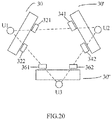
- FIG. 20 is a position view of cameras and translucent displays of the video communication system.
- connection may be such that the objects are permanently connected or releasably connected.
- substantially is defined to be essentially conforming to the particular dimension, shape, or other feature that the term modifies, such that the component need not be exact.
- comprising means “including, but not necessarily limited to”; it specifically indicates open-ended inclusion or membership in a so-described combination, group, series, and the like. It should be noted that references to “an” or “one” embodiment in this disclosure are not necessarily to the same embodiment, and such references mean “at least one.”
- FIG. 1 an embodiment of a video communication system 1 is provided.
- the video communication system 1 comprises a local video communication device 10 and a remote video communication device 10 ′.
- the local video communication device 10 and the remote video communication device 10 ′ are connected with each other through wired and/or wireless connections, and used for communicating via video.
- the local video communication device 10 comprises a local translucent display device 11 and a local camera array 12 .
- the remote video communication device 10 ′ comprises a remote translucent display device 13 and a remote camera array 14 .
- the local camera array 12 is placed on the back of the local translucent display device 11 , and the local camera array 12 includes a plurality of local cameras.
- Video information captured by one or more local cameras corresponding to a position of a remote user's face on the local translucent display device 11 may be transmitted to the remote video communication device 10 ′.
- the remote camera array 14 is placed on the back of the remote translucent display device 13 , and the remote camera array 14 includes a plurality of remote cameras. Video information captured by one or more remote cameras corresponding to a position of a local user's face on the remote translucent display device 13 may be transmitted to the local video communication device 10 . Since the local video communication device 10 and the remote video communication device 10 ′ have the same structure and functionalities, only the structure and functionalities of the local video communication device 10 are described in detail below.
- the local translucent display device 11 is used to display remote video information.
- the remote video information is captured by the remote camera array 14 and transmitted to the local translucent display device 11 .
- the local translucent display device 11 is translucent, so that objects in front of the translucent display device may be captured from the back of the translucent display device 11 .
- the local translucent display device 11 is a naked-eye three-dimensional (3D) display.
- the naked-eye 3D display comprises a plurality of pixel units 112 a spaced from one another, and an area between two adjacent pixel units 112 a is defined as an interval area 112 b .
- the interval areas 112 b are transparent so that light may pass through the interval areas 112 b .
- the pixel unit 112 a is non-transparent for displaying video information.
- the naked-eye 3D display may simultaneously provide video information to a plurality of local users located in different directions, and simultaneously display different video information to the plurality of local users according to the different directions of the plurality of local users.
- a display area of each pixel unit 112 a in the naked-eye 3D display may be equally divided into N units to accommodate different viewing angles and/or positions, and N is greater than or equal to two.
- the display area of each pixel unit 112 a in the naked-eye 3D display is divided into three units, and the video information displayed in the three units of the naked-eye 3D display are different, and the three units may be defined as unit a, unit b, and unit c.
- the video information seen by each of the users A, B and C is different.
- the scene in front of the translucent display can be captured by human eyes or the local camera 12 on the back of the translucent display through the interval areas 112 b.
- the local video communication device 10 further comprises a micro processing unit 100 .
- the micro processing unit 100 comprises a video capture and processing module 101 , a location acquisition module 102 , a sound processing module 103 , a communication module 104 , a display module 105 , and a central control module 107 .
- the video capture and processing module 101 is used to capture and process the local user's video information. Processing the local user's video information includes clipping the video information, correcting distorted video information, and calculating the occlusion relationship of the scene.
- the video capture and processing module 101 may control the plurality of local cameras to work simultaneously, and only select video information captured by one or more local cameras corresponding to the remote user's face image position, and process the video information.
- Local cameras of the local camera array 12 may also work selectively, and the video capture and processing module 101 may select one or more local cameras corresponding to the remote user's face image position to work, and process the video information captured by the one or more local cameras.
- the location acquisition module 102 is used to obtain each local user's face image position. In one embodiment, the location acquisition module 102 may be used to obtain the local user's eyes image position.
- the sound processing module 103 may be used to control the sound playback of video information and to capture local sounds.
- the communication module 104 may be used to communicate with the remote video communication device 10 ′, such as receiving video information and position information from the remote video communication device 10 ′, and transmitting video information and position information to the remote video communication device 10 ′.
- the display module 105 may be used to display the remote video information.
- the display module 105 may be further used to display different remote video information according to each local user's different visual direction.
- the central control module 107 may be used to coordinate and control the other modules.
- the position information obtained by the location acquisition module 102 may be transmitted to the video capture and processing module 101 by the central control module 107 , thereby video information conforming to a three-dimensional relationship can be generated.
- the local camera array 12 may be used to capture local user's video information, which may be transmitted to the remote video communication device 10 ′.
- the local camera array 12 is placed on the back of the local translucent display device 11 . Since the local translucent display device 11 is translucent, the local camera array 12 may capture the scene of the local user in front of the local translucent display device 11 .
- the local camera array 12 may be further arranged in a two-dimensional camera array.
- the plurality of local cameras of the local camera array 12 may work simultaneously.
- the video capture and processing module 101 controls the plurality of local cameras to work simultaneously, selects video information of one or more local cameras, and calculates the video information to generate a video screen.
- the position of the one or more local cameras may correspond to the position of the remote user's face image.
- the plurality of local cameras of the local camera array 12 may also work selectively, the video capture and processing module 101 may select one or more local cameras to work, and the position of the one or more local cameras may correspond to the position of the remote user's face image.
- the video information of the one or more local cameras may be synthesized into an integrated video to be transmitted to the remote video communication device 10 ′.
- the plurality of remote users in the screen correspond to a plurality of local cameras.
- Video information captured by the plurality of local cameras may be simultaneously transmitted to the remote video communication device 10 ′.
- the positions of the remote users' images change, the positions of the plurality of local cameras corresponding to the remote users' images also change.
- the positions of the remote users' images corresponding to the local cameras refer to positions of the remote users' face images.
- the positions of the remote users' images corresponding to the local cameras refer to positions of the remote users' eyes' images, therefore local users and remote users can have a real experience of looking at each other.
- the local cameras corresponding to the remote users' images are equivalent to the eyes of the remote users.
- the corresponding local cameras change accordingly.
- the local cameras in different positions capture different video information. Therefore, the video information seen by the moving remote users may vary.
- the video capture and processing module 101 can select cameras to accurately capture the corresponding video information according to the positions of the remote users' images, thereby allowing the remote users to have an immersive experience.
- a remote user's face image corresponds to a single camera
- the video capture and processing module 101 selects video information captured by the single camera.
- the remote user's face image becomes larger and corresponds to a plurality of cameras
- the video capture and processing module 101 selects video information captured by one of the plurality of cameras which is closest to the local user's eyes image.
- the video capture and processing module 101 selects video information captured by two cameras corresponding to both eyes and forms an integrated video, or the video capture and processing module 101 can also select video information captured by the camera which corresponds to the middle position of between the two eyes.
- the video capture and processing module 101 selects video information captured by one of the plurality of cameras which is closest to the local user's pupil of that eye.
- the local camera array 12 may include a binocular camera.
- the binocular camera may simulate the binocular vision of human eyes to capture scene information, and calculate the scene information in three dimensions to obtain the depth information of the scene.
- the depth information between a local user and the local translucent display device 11 may be obtained by the local camera array 12 , then the depth information may be transmitted to the remote video communication device 10 ′, and the remote video communication device 10 ′ may select the video information according to the depth information.
- the local user's field of view is large.
- the local user's field of view becomes smaller than that at position N.
- the remote camera array 14 is equivalent to the local user's eyes.
- the local user may move back and forth in front of the local translucent display device 11 , but the distance between the remote camera array 14 and the remote translucent display device 13 is constant, thus the remote camera array 14 needs to shoot a large field of view for selection.
- the viewing angle of the remote camera array 14 reaches 180 degrees.
- the display module 105 may select the corresponding video information from a large field of view according to the position of the local user.
- the local camera array 12 and the remote camera array 14 may include cameras with wide angles and/or high pixels.
- the depth information may also be obtained by the location acquisition module 102 , or by calculating data using cloud computing, and the data is send to the cloud by the location acquisition module 102 .
- the transmission of the depth information may be performed by the communication module 104 .
- the local camera may further include four camera units arranged in a crossover manner, for example, to calculate the occlusion relationship in the vertical direction.
- the local video communication device 10 may further include a depth sensor 120 to specifically sense the depth information.
- the local video communication device 10 may further include a speaker array 17 .
- the speaker array 17 may be distributed on the back of the local translucent display device 11 .
- the speaker array 17 may be used to play the remote user's voice according to the source location of the remote user.
- the speaker array 17 may also be arranged to be beyond the range of the local translucent display device 11 to simulate a sound source outside the field of view.
- the speaker array 17 allows the local user to have an immersive feeling. For example, if there is a cat howling near the remote video communication device 10 ′, but the cat is out of the video screen, the local user can still hear the cat's voice.
- FIG. 1 the local video communication device 10 ′
- the local video communication device 10 may further include a plurality of stereo microphones 18 , and the plurality of stereo microphones 18 is placed in front of the local translucent display device 11 .
- the plurality of stereo microphones 18 is used to collect local sounds for transmission to each other.
- the advantages of the local video communication device 10 may include, but are not limited to, the following.
- a camera array is placed behind a translucent screen, and video information of one or more cameras may be selected according to the position of the remote user's face image displayed on the translucent screen.
- the camera may capture the local user's face, and the local user and the remote user can look directly into each other's eyes.
- the local video communication device 10 provides users with an experience as if only a piece of transparent glass is placed between the local user and the remote user, which greatly increases the immersiveness.
- the local user and the remote user may feel like communicating with each other as if they are talking to each other on opposite sides of a glass.
- FIG. 10 another embodiment of a video communication system 2 is provided.
- the video communication system 2 comprises a local translucent display device 11 , a local camera array 12 , a local identification device 15 , a remote translucent display device 13 , a remote camera array 14 and a remote identification device 16 .
- the local identification device 15 is placed on the local translucent display device 11 .
- the local identification device 15 may be used to identify position information of the local users' faces.
- One or more local cameras of the local camera array 12 corresponding to the position of the remote user's image may be selected.
- the remote identification device 16 is placed on the remote translucent display device 13 .
- the remote identification device 16 is used to identify position information of the remote users' face.
- One or more remote cameras of the remote camera 14 corresponding to the position of the local user's image may be selected.
- the video communication system 2 is similar to the video communication system 1 in FIG. 1 .
- the video communication system 2 includes the local identification device 15 and the remote identification device 16 .
- the local identification device 15 may identify the position information of local users and transmit the position information to the remote camera array 14 .
- the local camera array 12 may be used to capture video information of local users.
- the remote identification device 16 may identify the position information of remote users and transmit the position information to the local camera array 12 .
- the remote camera array 14 may be used to capture video information of remote users.
- the local identification device 15 and the remote identification device 16 may include one or more of optical cameras, infrared cameras, position detection units for use with position sensor worn by the user.
- the local identification device 15 and the remote identification device 16 are both Kinect devices and used to identify the position information of the user eyes.
- FIG. 11 an embodiment of a method for video communication suitable for local video communication device 10 is provided.
- the method comprises:
- the remote video information is captured by the remote camera 14 .
- the remote camera array 14 is placed on the back of the remote translucent display device 13 , and the remote camera array 14 may capture the remote video information through the remote translucent display device 13 .
- a camera captures video information through a translucent display device
- light emitted by the pixel does not enter the back of the translucent display device due to the obstruction of a light shielding layer under the pixel, and the camera cannot be disturbed. Therefore, during the operation of the translucent display device, the camera on the back of the translucent display device may also work in real time.
- an image display frame of the translucent display device and an image acquisition frame of the camera may be staggered. In FIG.
- the image display frame of the translucent display device and the image acquisition frame of the camera may be alternately performed one frame by one frame.
- the image display frame is switched on, the image acquisition frame is turned off; when the image display frame is turned off, the image acquisition frame is switched on. Since the image display frame and the image acquisition frame are alternately performed very fast, and human eyes cannot distinguish, it does not affect human's video communication experience.
- the plurality of remote users correspond to the plurality of remote cameras, and the plurality of remote cameras may each capture video information.
- the plurality of video information is processed by the remote video communication device 10 ′ to form a remote video information.
- the local video communication device 10 may receive the remote video information through the communication module 104 .
- the remote video information is displayed on the local translucent display device 11 by the display module 105 .
- the local translucent display device 11 is a naked-eye 3D display, the naked-eye 3D display may display different video information to the plurality of local users according to the different directions of the plurality of local users.
- the position of remote user's image on the local translucent display device 11 may be obtained by the following methods:
- Method 1 the position of the user by an identification device is obtained.
- the identification device may be placed in front of the translucent display device to identify the remote user's face.
- the identification device may be optical cameras, infrared cameras, position detection units for use with position sensor worn by the remote user.
- Method 2 a relative position of the remote user in video captured by the camera is obtained, and the position of the remote user according to the position of the camera and the relative position of the remote user is calculated.
- the “relative position of the user” means that the position of remote user in the video.
- the local cameras corresponding to the position of remote users' image on the local translucent display device 11 may be selected from the local camera array 12 by the video capture and processing module 101 . Since the local cameras is placed behind the position of the remote user's image on the local translucent display device 11 , when the local user looks at the position of the remote user's eyes on the local translucent display device 11 , the local cameras may capture the local user's face, and the local user and the remote user can look directly into each other's eyes. The local video information captured by the local cameras may be transmitted to the remote video communication device 10 ′ by the communication module 104 .
- an initial camera may be selected from the camera array to work when there is no user in front of the video communication device, and the initial camera may be any camera of the camera array.
- the remote user leaves the room where the video communication system is located, which exceeds the field of view of the remote camera array 14 , there is no camera of the camera array 12 corresponding to the remote user.
- the field of the video played by the remote translucent display device 13 is no longer changed.
- the cameras of the remote camera array 14 still work according to the position of the local user, and the local user may still see remote video information with different view fields.
- the advantages of the method for video communication may include, but are not limited to, the following.
- the local user and the remote user can look at each other's eyes during video communication by selecting the cameras in real time.
- the method improves the interactive experience of the users.
- the video information that the user sees changes accordingly, and the user's immersive experience is also improved.
- the video communication system 3 comprises a plurality of video communication devices.
- the plurality of video communication devices is respectively used as a plurality of user terminals.
- the plurality of video communication devices is connected to one another through wired and/or wireless connections.
- the video communication system 3 comprises three video communication devices, such as a first video communication device 30 , a second video communication device 30 ′, a third video communication device 30 ′′.
- the first video communication device 30 is used as a first user terminal for a first user (U 1 ).
- the second video communication device 30 ′ is used as a second user terminal for a second user (U 2 ).
- the third video communication device 30 ′′ is used as a third user terminal for a third user (U 3 ).
- the first video communication device 30 comprises a translucent display 31 and a local camera array 32 .
- the local camera array 32 is placed on the back of the translucent display 31 .
- Video information captured by a camera of the local camera array 32 that is corresponding to a position of the second user's image displayed on the translucent display 31 is transmitted to the second video communication device 30 ′.
- Video information captured by a camera of the local camera array 32 that is corresponding to a position of the third user's image displayed on the translucent display 31 is transmitted to the third video communication device 30 ′′.
- the second video communication device 30 ′ comprises a translucent display 33 and a local camera array 34 .
- the local camera array 34 is placed on the back of the translucent display 33 .
- Video information captured by a camera of the local camera array 34 that is corresponding to a position of the first user's image displayed on the translucent display 33 is transmitted to first video communication device 30 .
- Video information captured by a camera of the local camera array 34 that is corresponding to a position of the third user's image displayed on the translucent display 33 is transmitted to the third video communication device 30 ′′.
- the third video communication device 30 ′′ comprises a translucent display 35 and a local camera array 36 .
- the local camera array 36 is placed on the back of the translucent display 35 .
- Video information captured by a camera of the local camera array 36 which is corresponding to a position of the first user's image displayed on the translucent display 35 , is transmitted to the first video communication device 30 .
- Video information captured by a camera of the local camera array 36 which is corresponding to a position of the second user's image displayed on the translucent display 35 , is transmitted to the second video communication device 30 ′. Since the structures and functions of the first video communication device 30 , the second video communication device 30 ′, and the third video communication device 30 ′′ are substantially the same, only the first video communication device 30 is described in detail below.
- the translucent display 31 is used to display video information received from other two user terminals.
- the video information received from other two user terminals may be displayed by two virtual windows 310 disposed at different positions of the translucent display 31 .
- the first user is defined as to U 1
- the second user is defined as to U 2
- the third user is defined as to U 3 .
- the user U 1 may respectively see video information of U 2 and U 3 through the two virtual windows 310 displayed on the translucent display 31 .
- the number of virtual windows 310 , the order of virtual windows 310 and the size of virtual windows 310 may be adjusted according to numbers of user terminals.
- the translucent display 31 is translucent, and it means that the scene in front of the translucent display 31 may be captured by the local camera array 32 located at the back of the translucent display 31 .
- the translucent display 31 comprises a plurality of pixel units 112 a spaced from one another, and the area between two adjacent pixel units 112 a is defined as an interval area 112 b .
- the interval area 112 b is transparent and a light transmission area.
- the pixel unit 112 a is a non-transparent area for displaying video information.
- the scene in front of the translucent display 31 may be captured by human eyes or the camera array 32 from the back of the translucent display 31 through the interval area 112 b.
- the translucent display 31 further comprises a micro processing unit 300 .
- the micro processing unit 300 comprises a video capture and processing module 301 , a location acquisition module 302 , a sound processing module 303 , a communication module 304 , a display module 305 , and a central control module 307 .
- the video capture and processing module 301 is used to capture and process the local user's video information. Processing the local user's video information includes clipping the video information, correcting distorted video information, and calculating the occlusion relationship of the scene.
- the location acquisition module 302 is used to obtain each local user's face position. In one embodiment, the location acquisition module 302 is used to obtain the local user's eyes image position.
- the sound processing module 303 is used to control the sound playback of video information and to capture local sounds.
- the communication module 304 is used to communicate with the second video communication device 30 ′ and the third video communication device 30 ′′, such as receiving video information and position information from the second video communication device 30 ′ and the third video communication device 30 ′′, or transmitting video information and position information to the second video communication device 30 ′ and the third video communication device 30 ′′.
- the display module 305 is used to set a plurality of virtual windows 310 and display video information through the plurality of virtual windows 310 .
- the central control module 307 is used to coordinate and control the other modules.
- the video information of the user U 1 and the user U 2 are displayed on the translucent display 31 through the virtual windows 310 .
- the virtual windows 310 may be tiled on the translucent display 31 .
- the video information of the user U 1 and the user U 2 may also be corrected by the display module 305 and displayed in stereo on the translucent display 31 .
- the virtual windows 310 may be three-dimensional trapezoidal frames to display corrected video information. A relative position of the scene in the video information would not be changed after correction. For example, since the user U 2 is on one side of the virtual window before correction, the user U 2 is still on the side of the virtual window after correction; since the user U 3 is in the middle of the virtual window before correction, the user U 3 is still in the middle of the virtual window after correction.
- the user U 1 in front of the translucent display 31 may observe a scene that the image of user U 2 watches the image of user U 3 .
- the positions of the virtual windows may be adjusted according to the number of user terminals.
- the camera array 32 is substantially the same as the camera array 12 in FIG. 1 .
- the method of selecting a camera from the camera array 32 is also substantially the same as the method of selecting a camera from the camera array 12 . Since different video information displayed on the translucent display 31 are from a plurality of video communication devices, video captured by cameras corresponding to different users' images may be transmitted to different video communication devices.
- the advantages of the video communication device 30 may include, but are not limited to, the following.
- a camera array is placed behind a translucent screen, and video information of a plurality of cameras may be selected according to the image position of a plurality of remote users displayed on the translucent screen.
- the plurality of cameras may capture the local user's face, and the local user and the remote users can look directly into each other's eyes.
- the video communication device 30 provides users with an experience as if only a piece of transparent glass is placed between the local user and the remote user, which greatly increases the immersiveness.
- the local user and the remote user may feel like communicating with each other as if they are talking to each other on opposite sides of a glass.
- FIG. 18 an embodiment of a method for video communication suitable for the first video communication device 30 in FIG. 13 is provided.
- the method comprises:
- the method of receiving a second video information from the second video communication device 30 ′ and a third video information from the third video communication device 30 ′′ is similar with the method of receiving remote video information from the remote video communication device 10 ′ in FIG. 10 .
- the first video communication device 30 can get both the second video information and the third video information at the same time.
- the video capture and processing module 301 may set the number and arrangement of the virtual windows 310 according to the specific needs.
- the virtual windows 310 are three-dimensional trapezoidal frames to display corrected video information.
- the video information received from different video communication devices are displayed in different virtual windows 310 .
- a plurality of virtual windows 310 are arranged in a row, and each of the plurality of virtual windows 310 is distributed independently on a display.
- the method of acquiring the position of the second user's image and the third user's image on the translucent display 31 is substantially the same as the method of obtaining the position of remote user's image on the local translucent display device 11 .
- the method of selecting the second camera and the third camera is substantially the same as the method of selecting the local cameras of action 1104 .
- a first camera 321 and a second camera 322 of the local camera array 32 are selected, the first camera 321 corresponds to the position of the user U 2 's image, and the second camera 322 corresponds to the position of user U 3 's image.
- a first video information captured by the first camera 321 is transmitted to the second video communication device 30 ′ used by the user U 2 .
- a second video information captured by the second camera 322 is transmitted to the third video communication device 30 ′′ used by the user U 3 .
- a third video information captured by a third camera 341 is transmitted to the first video communication device 30 used by the user U 1 .
- a forth video information captured by a forth camera 342 is transmitted to the third video communication device 30 ′′ used by the user U 3 .
- a fifth video information captured by a fifth camera 361 is transmitted to the first video communication device 30 used by the user U 1 .
- a sixth video information captured by a sixth camera 362 is transmitted to the second video communication device 30 ′ used by the user U 2 .
Landscapes
- Engineering & Computer Science (AREA)
- Multimedia (AREA)
- Signal Processing (AREA)
- General Physics & Mathematics (AREA)
- Physics & Mathematics (AREA)
- Theoretical Computer Science (AREA)
- Human Computer Interaction (AREA)
- Health & Medical Sciences (AREA)
- General Health & Medical Sciences (AREA)
- Computer Vision & Pattern Recognition (AREA)
- Ophthalmology & Optometry (AREA)
- Oral & Maxillofacial Surgery (AREA)
- General Engineering & Computer Science (AREA)
- Two-Way Televisions, Distribution Of Moving Picture Or The Like (AREA)
Abstract
Description
-
-
action 1101, receiving remote video information from the remotevideo communication device 10′; -
action 1102, displaying the remote video information on the localtranslucent display device 11; -
action 1103, obtaining the positions of a plurality of remote users' images on the localtranslucent display device 11; - action 1104, selecting local cameras corresponding to the position of remote users' image on the local
translucent display device 11 from thelocal camera array 12, and transmitting local video information captured by the local cameras to the remotevideo communication device 10′.
-
-
-
action 1801, receiving a second video information from the secondvideo communication device 30′ and a third video information from the thirdvideo communication device 30″; -
action 1802, displaying the second video information in onevirtual window 310 of thetranslucent display 31 and the third video information in anothervirtual window 310 of thetranslucent display 31; -
action 1803, receiving the position of the second user's image and the third user's image displayed on thetranslucent display 31; -
action 1804, selecting a second camera corresponding to the position of the second user's image displayed on the firsttranslucent display 31 from thelocal camera array 32, and selecting a third camera corresponding to the position of the third user's image displayed on the firsttranslucent display 31 from thelocal camera array 32, and transmitting video information captured by the second camera to the secondvideo communication device 30′, and transmitting video information captured by the third camera to the thirdvideo communication device 30″.
-
Claims (15)
Applications Claiming Priority (3)
| Application Number | Priority Date | Filing Date | Title |
|---|---|---|---|
| CN201810264461.8A CN110324555B (en) | 2018-03-28 | 2018-03-28 | Video communication apparatus and method |
| CN201810264461.8 | 2018-03-28 | ||
| CN201810264461 | 2018-03-28 |
Publications (2)
| Publication Number | Publication Date |
|---|---|
| US20190306457A1 US20190306457A1 (en) | 2019-10-03 |
| US10645340B2 true US10645340B2 (en) | 2020-05-05 |
Family
ID=68054052
Family Applications (1)
| Application Number | Title | Priority Date | Filing Date |
|---|---|---|---|
| US16/367,693 Active US10645340B2 (en) | 2018-03-28 | 2019-03-28 | Video communication device and method for video communication |
Country Status (3)
| Country | Link |
|---|---|
| US (1) | US10645340B2 (en) |
| CN (1) | CN110324555B (en) |
| TW (1) | TWI698128B (en) |
Cited By (1)
| Publication number | Priority date | Publication date | Assignee | Title |
|---|---|---|---|---|
| US20230410760A1 (en) * | 2022-06-21 | 2023-12-21 | Japan Display Inc. | Electronic apparatus |
Families Citing this family (2)
| Publication number | Priority date | Publication date | Assignee | Title |
|---|---|---|---|---|
| JP6942374B2 (en) * | 2019-10-25 | 2021-09-29 | 株式会社ジュリア | Information management system, server and user terminal |
| US20230138733A1 (en) * | 2021-10-31 | 2023-05-04 | Zoom Video Communications, Inc. | Representation of natural eye contact within a video conferencing session |
Citations (21)
| Publication number | Priority date | Publication date | Assignee | Title |
|---|---|---|---|---|
| US4928301A (en) * | 1988-12-30 | 1990-05-22 | Bell Communications Research, Inc. | Teleconferencing terminal with camera behind display screen |
| US5953053A (en) * | 1998-09-02 | 1999-09-14 | Motorola, Inc. | Teleconference system with visual display terminal |
| TWI248021B (en) | 2001-03-21 | 2006-01-21 | Wistron Corp | Method and system for correcting out-of-focus eyesight of attendant images in video conferencing |
| US20070002130A1 (en) * | 2005-06-21 | 2007-01-04 | David Hartkop | Method and apparatus for maintaining eye contact during person-to-person video telecommunication |
| US20080043100A1 (en) | 2006-07-31 | 2008-02-21 | Irwin Sobel | Projection screen and camera array |
| US20090102763A1 (en) | 2007-10-19 | 2009-04-23 | Border John N | Display device with capture capabilities |
| US20090278913A1 (en) | 2008-05-12 | 2009-11-12 | Microsoft Corporation | Gaze accurate video conferencing |
| US7865834B1 (en) * | 2004-06-25 | 2011-01-04 | Apple Inc. | Multi-way video conferencing user interface |
| US20110096136A1 (en) * | 2009-05-12 | 2011-04-28 | Huawei Device Co., Ltd. | Telepresence system, telepresence method, and video collection device |
| US20120081504A1 (en) * | 2010-09-30 | 2012-04-05 | Alcatel-Lucent Usa, Incorporated | Audio source locator and tracker, a method of directing a camera to view an audio source and a video conferencing terminal |
| EP2509309A1 (en) | 2011-04-05 | 2012-10-10 | Polycom, Inc. | Direct eye-contact enhancing videoconferencing unit |
| US20130271560A1 (en) * | 2012-04-11 | 2013-10-17 | Jie Diao | Conveying gaze information in virtual conference |
| US20140146127A1 (en) * | 2012-11-29 | 2014-05-29 | Cisco Technology, Inc. | Capturing Video through a Display |
| CN203966475U (en) | 2014-04-30 | 2014-11-26 | 深圳市联建光电股份有限公司 | There is the LED display system of multiple cameras |
| US8970663B2 (en) * | 2009-12-07 | 2015-03-03 | Hewlett-Packard Development Company, L.P. | 3D video conference |
| US8976221B2 (en) * | 2012-12-03 | 2015-03-10 | Google Inc. | Adaptable identification of relevant regions in live streams |
| US9300916B1 (en) * | 2015-02-10 | 2016-03-29 | International Business Machines Corporation | Natural gazes during online video conversations |
| US9462223B2 (en) | 2004-04-21 | 2016-10-04 | Telepresence Technologies, Llc | Telepresence systems and methods therefore |
| US20170264865A1 (en) | 2015-05-29 | 2017-09-14 | Boe Technology Group Co., Ltd. | Display device and video communication terminal |
| US9843713B2 (en) * | 2014-04-02 | 2017-12-12 | Nebulys Technologies, Inc. | Systems and methods for video communication |
| US20180367756A1 (en) * | 2017-06-15 | 2018-12-20 | Shenzhen Optical Crystal LTD, Co. | Video conference system utilizing transparent screen |
Family Cites Families (7)
| Publication number | Priority date | Publication date | Assignee | Title |
|---|---|---|---|---|
| US8243119B2 (en) * | 2007-09-30 | 2012-08-14 | Optical Fusion Inc. | Recording and videomail for video conferencing call systems |
| US8319819B2 (en) * | 2008-03-26 | 2012-11-27 | Cisco Technology, Inc. | Virtual round-table videoconference |
| EP2692133B1 (en) * | 2011-03-31 | 2019-01-16 | SMART Technologies ULC | Video conferencing display device |
| CN203554588U (en) * | 2012-04-09 | 2014-04-16 | 廖文瑾 | Video communication system |
| JP2013235562A (en) * | 2012-05-04 | 2013-11-21 | Commonwealth Scientific & Industrial Research Organization | System and method for eye position on video |
| CN102761732B (en) * | 2012-07-25 | 2018-04-27 | 鲁懿齐 | A kind of video conference Eye-to-eye communication system |
| US9743040B1 (en) * | 2015-12-03 | 2017-08-22 | Symantec Corporation | Systems and methods for facilitating eye contact during video conferences |
-
2018
- 2018-03-28 CN CN201810264461.8A patent/CN110324555B/en active Active
- 2018-10-18 TW TW107136640A patent/TWI698128B/en active
-
2019
- 2019-03-28 US US16/367,693 patent/US10645340B2/en active Active
Patent Citations (23)
| Publication number | Priority date | Publication date | Assignee | Title |
|---|---|---|---|---|
| US4928301A (en) * | 1988-12-30 | 1990-05-22 | Bell Communications Research, Inc. | Teleconferencing terminal with camera behind display screen |
| US5953053A (en) * | 1998-09-02 | 1999-09-14 | Motorola, Inc. | Teleconference system with visual display terminal |
| TWI248021B (en) | 2001-03-21 | 2006-01-21 | Wistron Corp | Method and system for correcting out-of-focus eyesight of attendant images in video conferencing |
| US9462223B2 (en) | 2004-04-21 | 2016-10-04 | Telepresence Technologies, Llc | Telepresence systems and methods therefore |
| US7865834B1 (en) * | 2004-06-25 | 2011-01-04 | Apple Inc. | Multi-way video conferencing user interface |
| US20070002130A1 (en) * | 2005-06-21 | 2007-01-04 | David Hartkop | Method and apparatus for maintaining eye contact during person-to-person video telecommunication |
| US20080043100A1 (en) | 2006-07-31 | 2008-02-21 | Irwin Sobel | Projection screen and camera array |
| US20090102763A1 (en) | 2007-10-19 | 2009-04-23 | Border John N | Display device with capture capabilities |
| TW200923495A (en) | 2007-10-19 | 2009-06-01 | Eastman Kodak Co | Display device with capture capabilities |
| US20090278913A1 (en) | 2008-05-12 | 2009-11-12 | Microsoft Corporation | Gaze accurate video conferencing |
| TW200948070A (en) | 2008-05-12 | 2009-11-16 | Microsoft Corp | Gaze accurate video conferencing |
| US20110096136A1 (en) * | 2009-05-12 | 2011-04-28 | Huawei Device Co., Ltd. | Telepresence system, telepresence method, and video collection device |
| US8970663B2 (en) * | 2009-12-07 | 2015-03-03 | Hewlett-Packard Development Company, L.P. | 3D video conference |
| US20120081504A1 (en) * | 2010-09-30 | 2012-04-05 | Alcatel-Lucent Usa, Incorporated | Audio source locator and tracker, a method of directing a camera to view an audio source and a video conferencing terminal |
| EP2509309A1 (en) | 2011-04-05 | 2012-10-10 | Polycom, Inc. | Direct eye-contact enhancing videoconferencing unit |
| US20130271560A1 (en) * | 2012-04-11 | 2013-10-17 | Jie Diao | Conveying gaze information in virtual conference |
| US20140146127A1 (en) * | 2012-11-29 | 2014-05-29 | Cisco Technology, Inc. | Capturing Video through a Display |
| US8976221B2 (en) * | 2012-12-03 | 2015-03-10 | Google Inc. | Adaptable identification of relevant regions in live streams |
| US9843713B2 (en) * | 2014-04-02 | 2017-12-12 | Nebulys Technologies, Inc. | Systems and methods for video communication |
| CN203966475U (en) | 2014-04-30 | 2014-11-26 | 深圳市联建光电股份有限公司 | There is the LED display system of multiple cameras |
| US9300916B1 (en) * | 2015-02-10 | 2016-03-29 | International Business Machines Corporation | Natural gazes during online video conversations |
| US20170264865A1 (en) | 2015-05-29 | 2017-09-14 | Boe Technology Group Co., Ltd. | Display device and video communication terminal |
| US20180367756A1 (en) * | 2017-06-15 | 2018-12-20 | Shenzhen Optical Crystal LTD, Co. | Video conference system utilizing transparent screen |
Cited By (1)
| Publication number | Priority date | Publication date | Assignee | Title |
|---|---|---|---|---|
| US20230410760A1 (en) * | 2022-06-21 | 2023-12-21 | Japan Display Inc. | Electronic apparatus |
Also Published As
| Publication number | Publication date |
|---|---|
| CN110324555B (en) | 2021-02-26 |
| US20190306457A1 (en) | 2019-10-03 |
| CN110324555A (en) | 2019-10-11 |
| TWI698128B (en) | 2020-07-01 |
| TW202005366A (en) | 2020-01-16 |
Similar Documents
| Publication | Publication Date | Title |
|---|---|---|
| US10750210B2 (en) | Three-dimensional telepresence system | |
| US10623698B2 (en) | Video communication device and method for video communication | |
| US11006072B2 (en) | Window system based on video communication | |
| US20160269685A1 (en) | Video interaction between physical locations | |
| US10645340B2 (en) | Video communication device and method for video communication | |
| US10972699B2 (en) | Video communication device and method for video communication | |
| WO2003098942A1 (en) | Information processing apparatus, information processing system, and dialogist displaying method | |
| CN204681518U (en) | A kind of panorama image information collecting device | |
| US10701313B2 (en) | Video communication device and method for video communication | |
| WO2017092369A1 (en) | Head-mounted device, three-dimensional video call system and three-dimensional video call implementation method | |
| WO2023128760A1 (en) | Scaling of three-dimensional content for display on an autostereoscopic display device | |
| CN112558769A (en) | External front side display screen control method and control method of multiple virtual characters |
Legal Events
| Date | Code | Title | Description |
|---|---|---|---|
| AS | Assignment |
Owner name: BEIJING FUNATE INNOVATION TECHNOLOGY CO., LTD., CH Free format text: ASSIGNMENT OF ASSIGNORS INTEREST;ASSIGNOR:LIU, LIANG;REEL/FRAME:048728/0233 Effective date: 20190301 Owner name: BEIJING FUNATE INNOVATION TECHNOLOGY CO., LTD., CHINA Free format text: ASSIGNMENT OF ASSIGNORS INTEREST;ASSIGNOR:LIU, LIANG;REEL/FRAME:048728/0233 Effective date: 20190301 |
|
| FEPP | Fee payment procedure |
Free format text: ENTITY STATUS SET TO UNDISCOUNTED (ORIGINAL EVENT CODE: BIG.); ENTITY STATUS OF PATENT OWNER: LARGE ENTITY |
|
| STPP | Information on status: patent application and granting procedure in general |
Free format text: NON FINAL ACTION MAILED |
|
| STPP | Information on status: patent application and granting procedure in general |
Free format text: RESPONSE TO NON-FINAL OFFICE ACTION ENTERED AND FORWARDED TO EXAMINER |
|
| STPP | Information on status: patent application and granting procedure in general |
Free format text: RESPONSE AFTER FINAL ACTION FORWARDED TO EXAMINER |
|
| STPP | Information on status: patent application and granting procedure in general |
Free format text: NOTICE OF ALLOWANCE MAILED -- APPLICATION RECEIVED IN OFFICE OF PUBLICATIONS |
|
| STCF | Information on status: patent grant |
Free format text: PATENTED CASE |
|
| MAFP | Maintenance fee payment |
Free format text: PAYMENT OF MAINTENANCE FEE, 4TH YEAR, LARGE ENTITY (ORIGINAL EVENT CODE: M1551); ENTITY STATUS OF PATENT OWNER: LARGE ENTITY Year of fee payment: 4 |