US10641069B2 - Flow control in subterranean wells - Google Patents
Flow control in subterranean wells Download PDFInfo
- Publication number
- US10641069B2 US10641069B2 US14/698,578 US201514698578A US10641069B2 US 10641069 B2 US10641069 B2 US 10641069B2 US 201514698578 A US201514698578 A US 201514698578A US 10641069 B2 US10641069 B2 US 10641069B2
- Authority
- US
- United States
- Prior art keywords
- well
- flow
- opening
- fibers
- conveyed
- Prior art date
- Legal status (The legal status is an assumption and is not a legal conclusion. Google has not performed a legal analysis and makes no representation as to the accuracy of the status listed.)
- Active, expires
Links
- 238000000034 method Methods 0.000 claims abstract description 38
- 239000000835 fiber Substances 0.000 claims abstract description 33
- 239000012530 fluid Substances 0.000 claims description 32
- 239000000463 material Substances 0.000 claims description 21
- 230000015572 biosynthetic process Effects 0.000 claims description 10
- 230000000593 degrading effect Effects 0.000 claims description 9
- 239000000203 mixture Substances 0.000 claims description 7
- 239000000126 substance Substances 0.000 claims description 5
- 206010073306 Exposure to radiation Diseases 0.000 claims description 4
- 239000004744 fabric Substances 0.000 description 11
- 238000005755 formation reaction Methods 0.000 description 9
- VTYYLEPIZMXCLO-UHFFFAOYSA-L Calcium carbonate Chemical compound [Ca+2].[O-]C([O-])=O VTYYLEPIZMXCLO-UHFFFAOYSA-L 0.000 description 8
- 238000011282 treatment Methods 0.000 description 6
- 239000004568 cement Substances 0.000 description 5
- 229920001778 nylon Polymers 0.000 description 5
- 239000004677 Nylon Substances 0.000 description 4
- 239000002253 acid Substances 0.000 description 4
- 229910000019 calcium carbonate Inorganic materials 0.000 description 4
- 238000004891 communication Methods 0.000 description 4
- 239000002657 fibrous material Substances 0.000 description 4
- 239000002245 particle Substances 0.000 description 4
- 238000005260 corrosion Methods 0.000 description 3
- 230000007797 corrosion Effects 0.000 description 3
- 239000004633 polyglycolic acid Substances 0.000 description 3
- 229950008885 polyglycolic acid Drugs 0.000 description 3
- 238000007789 sealing Methods 0.000 description 3
- 239000004626 polylactic acid Substances 0.000 description 2
- 230000005855 radiation Effects 0.000 description 2
- 239000002002 slurry Substances 0.000 description 2
- 238000006467 substitution reaction Methods 0.000 description 2
- 229910000838 Al alloy Inorganic materials 0.000 description 1
- 239000004215 Carbon black (E152) Substances 0.000 description 1
- 229910000861 Mg alloy Inorganic materials 0.000 description 1
- 150000007513 acids Chemical class 0.000 description 1
- 238000007792 addition Methods 0.000 description 1
- 230000009286 beneficial effect Effects 0.000 description 1
- 238000009954 braiding Methods 0.000 description 1
- 238000010276 construction Methods 0.000 description 1
- 238000012217 deletion Methods 0.000 description 1
- 230000037430 deletion Effects 0.000 description 1
- 230000005670 electromagnetic radiation Effects 0.000 description 1
- -1 etc.) Substances 0.000 description 1
- 239000002360 explosive Substances 0.000 description 1
- 238000007667 floating Methods 0.000 description 1
- 229930195733 hydrocarbon Natural products 0.000 description 1
- 150000002430 hydrocarbons Chemical class 0.000 description 1
- 238000012986 modification Methods 0.000 description 1
- 230000004048 modification Effects 0.000 description 1
- 239000007787 solid Substances 0.000 description 1
- XLYOFNOQVPJJNP-UHFFFAOYSA-N water Substances O XLYOFNOQVPJJNP-UHFFFAOYSA-N 0.000 description 1
- 238000009941 weaving Methods 0.000 description 1
Images


Classifications
-
- E—FIXED CONSTRUCTIONS
- E21—EARTH OR ROCK DRILLING; MINING
- E21B—EARTH OR ROCK DRILLING; OBTAINING OIL, GAS, WATER, SOLUBLE OR MELTABLE MATERIALS OR A SLURRY OF MINERALS FROM WELLS
- E21B43/00—Methods or apparatus for obtaining oil, gas, water, soluble or meltable materials or a slurry of minerals from wells
- E21B43/12—Methods or apparatus for controlling the flow of the obtained fluid to or in wells
-
- E—FIXED CONSTRUCTIONS
- E21—EARTH OR ROCK DRILLING; MINING
- E21B—EARTH OR ROCK DRILLING; OBTAINING OIL, GAS, WATER, SOLUBLE OR MELTABLE MATERIALS OR A SLURRY OF MINERALS FROM WELLS
- E21B17/00—Drilling rods or pipes; Flexible drill strings; Kellies; Drill collars; Sucker rods; Cables; Casings; Tubings
- E21B17/20—Flexible or articulated drilling pipes, e.g. flexible or articulated rods, pipes or cables
-
- E—FIXED CONSTRUCTIONS
- E21—EARTH OR ROCK DRILLING; MINING
- E21B—EARTH OR ROCK DRILLING; OBTAINING OIL, GAS, WATER, SOLUBLE OR MELTABLE MATERIALS OR A SLURRY OF MINERALS FROM WELLS
- E21B33/00—Sealing or packing boreholes or wells
- E21B33/10—Sealing or packing boreholes or wells in the borehole
- E21B33/13—Methods or devices for cementing, for plugging holes, crevices or the like
- E21B33/138—Plastering the borehole wall; Injecting into the formation
-
- E—FIXED CONSTRUCTIONS
- E21—EARTH OR ROCK DRILLING; MINING
- E21B—EARTH OR ROCK DRILLING; OBTAINING OIL, GAS, WATER, SOLUBLE OR MELTABLE MATERIALS OR A SLURRY OF MINERALS FROM WELLS
- E21B43/00—Methods or apparatus for obtaining oil, gas, water, soluble or meltable materials or a slurry of minerals from wells
- E21B43/25—Methods for stimulating production
- E21B43/26—Methods for stimulating production by forming crevices or fractures
- E21B43/261—Separate steps of (1) cementing, plugging or consolidating and (2) fracturing or attacking the formation
-
- C—CHEMISTRY; METALLURGY
- C09—DYES; PAINTS; POLISHES; NATURAL RESINS; ADHESIVES; COMPOSITIONS NOT OTHERWISE PROVIDED FOR; APPLICATIONS OF MATERIALS NOT OTHERWISE PROVIDED FOR
- C09K—MATERIALS FOR MISCELLANEOUS APPLICATIONS, NOT PROVIDED FOR ELSEWHERE
- C09K2208/00—Aspects relating to compositions of drilling or well treatment fluids
- C09K2208/08—Fiber-containing well treatment fluids
-
- E21B2034/007—
-
- E—FIXED CONSTRUCTIONS
- E21—EARTH OR ROCK DRILLING; MINING
- E21B—EARTH OR ROCK DRILLING; OBTAINING OIL, GAS, WATER, SOLUBLE OR MELTABLE MATERIALS OR A SLURRY OF MINERALS FROM WELLS
- E21B2200/00—Special features related to earth drilling for obtaining oil, gas or water
- E21B2200/06—Sleeve valves
-
- E—FIXED CONSTRUCTIONS
- E21—EARTH OR ROCK DRILLING; MINING
- E21B—EARTH OR ROCK DRILLING; OBTAINING OIL, GAS, WATER, SOLUBLE OR MELTABLE MATERIALS OR A SLURRY OF MINERALS FROM WELLS
- E21B43/00—Methods or apparatus for obtaining oil, gas, water, soluble or meltable materials or a slurry of minerals from wells
- E21B43/11—Perforators; Permeators
-
- E—FIXED CONSTRUCTIONS
- E21—EARTH OR ROCK DRILLING; MINING
- E21B—EARTH OR ROCK DRILLING; OBTAINING OIL, GAS, WATER, SOLUBLE OR MELTABLE MATERIALS OR A SLURRY OF MINERALS FROM WELLS
- E21B43/00—Methods or apparatus for obtaining oil, gas, water, soluble or meltable materials or a slurry of minerals from wells
- E21B43/14—Obtaining from a multiple-zone well
Definitions
- This disclosure relates generally to equipment utilized and operations performed in conjunction with a subterranean well and, in one example described below, more particularly provides for flow control in wells.
- FIG. 1 is a representative partially cross-sectional view of an example of a well system and associated method which can embody principles of this disclosure.
- FIGS. 2A-D are enlarged scale representative partially cross-sectional views of steps in an example of a re-completion method that may be practiced with the system of FIG. 1 .
- FIGS. 3A-D are representative partially cross-sectional views of steps in another example of a method that may be practiced with the system of FIG. 1 .
- FIG. 4 is an enlarged scale representative elevational view of a flow conveyed device that may be used in the system and methods of FIGS. 1-3D , and which can embody the principles of this disclosure.
- FIG. 5 is a representative elevational view of another example of the flow conveyed device.
- FIGS. 6A & B are representative partially cross-sectional views of the flow conveyed device in a well, the device being conveyed by flow in FIG. 6A , and engaging a casing opening in FIG. 6B .
- FIG. 1 Representatively illustrated in FIG. 1 is a system 10 for use with a well, and an associated method, which can embody principles of this disclosure.
- system 10 and method are merely one example of an application of the principles of this disclosure in practice, and a wide variety of other examples are possible. Therefore, the scope of this disclosure is not limited at all to the details of the system 10 and method described herein and/or depicted in the drawings.
- FIG. 1 a tubular string 12 is conveyed into a wellbore 14 lined with casing 16 and cement 18 .
- casing 16 and cement 18 .
- multiple casing strings would typically be used in actual practice, for clarity of illustration only one casing string 16 is depicted in the drawings.
- the wellbore 14 is illustrated as being vertical, sections of the wellbore could instead be horizontal or otherwise inclined relative to vertical. Although the wellbore 14 is completely cased and cemented as depicted in FIG. 1 , any sections of the wellbore in which operations described in more detail below are performed could be uncased or open hole. Thus, the scope of this disclosure is not limited to any particular details of the system 10 and method.
- the tubular string 12 of FIG. 1 comprises coiled tubing 20 and a bottom hole assembly 22 .
- coiled tubing refers to a substantially continuous tubing that is stored on a spool or reel 24 .
- the reel 24 could be mounted, for example, on a skid, a trailer, a floating vessel, a vehicle, etc., for transport to a wellsite.
- a control room or cab would typically be provided with instrumentation, computers, controllers, recorders, etc., for controlling equipment such as an injector 26 and a blowout preventer stack 28 .
- bottom hole assembly refers to an assembly connected at a distal end of a tubular string in a well. It is not necessary for a bottom hole assembly to be positioned or used at a “bottom” of a hole or well.
- annulus 30 is formed radially between them. Fluid, slurries, etc., can be flowed from surface into the annulus 30 via, for example, a casing valve 32 .
- One or more pumps 34 may be used for this purpose. Fluid can also be flowed to surface from the wellbore 14 via the annulus 30 and valve 32 .
- Fluid, slurries, etc. can also be flowed from surface into the wellbore 14 via the tubing 20 , for example, using one or more pumps 36 . Fluid can also be flowed to surface from the wellbore 14 via the tubing 20 .
- one or more flow conveyed devices are used to block or plug openings in the system 10 of FIG. 1 .
- the flow conveyed device may be used with other systems, and the flow conveyed device may be used in other methods in keeping with the principles of this disclosure.
- Flow conveyed device examples described below are made of a fibrous material and comprise a “knot” or other enlarged geometry.
- the devices are conveyed into leak paths using pumped fluid.
- the fibrous material “finds” and follows the fluid flow, pulling the enlarged geometry into a restricted portion of a flow path, causing the enlarged geometry and additional strands to become tightly wedged into the flow path thereby sealing off fluid communication.
- the devices can be made of degradable or non-degradable materials.
- the degradable materials can be either self-degrading, or can require degrading treatments, such as, by exposing the materials to certain acids, certain base compositions, certain chemicals, certain types of radiation (e.g., electromagnetic or “nuclear”), or elevated temperature.
- the exposure can be performed at a desired time using a form of well intervention, such as, by spotting or circulating a fluid in the well so that the material is exposed to the fluid.
- the material can be an acid degradable material (e.g., nylon, etc.), a mix of acid degradable material (for example, nylon fibers mixed with particulate such as calcium carbonate), self-degrading material (e.g., poly-lactic acid (PLA), poly-glycolic acid (PGA), etc.), material that degrades by galvanic action (such as, magnesium alloys, aluminum alloys, etc.), a combination of different self-degrading materials, or a combination of self-degrading and non-self-degrading materials.
- acid degradable material e.g., nylon, etc.
- a mix of acid degradable material for example, nylon fibers mixed with particulate such as calcium carbonate
- self-degrading material e.g., poly-lactic acid (PLA), poly-glycolic acid (PGA), etc.
- material that degrades by galvanic action such as, magnesium alloys, aluminum alloys, etc.
- a combination of different self-degrading materials
- nylon and calcium carbonate could be pumped as a mixture, or the nylon could be pumped first to initiate a seal, followed by calcium carbonate to enhance the seal.
- the device can be made of knotted fibrous materials. Multiple knots can be used with any number of loose ends. The ends can be frayed or un-frayed.
- the fibrous material can be rope, fabric, cloth or another woven or braided structure.
- the device can be used to block open sleeve valves, perforations or any leak paths in a well (such as, leaking connections in casing, corrosion holes, etc.). Any opening through which fluid flows can be blocked with a suitably configured device.
- a well with an existing perforated zone can be re-completed.
- Devices either degradable or non-degradable are conveyed by flow to plug all existing perforations.
- the well can then be re-completed using any desired completion technique. If the devices are degradable, a degrading treatment can then be placed in the well to open up the plugged perforations (if desired).
- multiple formation zones can be perforated and fractured in a single trip of the bottom hole assembly 22 into the well.
- one zone is perforated, the zone is fractured, and then the perforated zone is plugged using one or more devices.
- FIGS. 2A-D steps in an example of a method in which the bottom hole assembly 22 of FIG. 1 can be used in re-completing a well are representatively illustrated.
- the well has existing perforations 38 that provide for fluid communication between an earth formation zone 40 and an interior of the casing 16 .
- it is desired to re-complete the zone 40 in order to enhance the fluid communication.
- Plugs 42 in the perforations can be flow conveyed devices, as described more fully below. In that case, the plugs 42 can be conveyed through the casing 16 and into engagement with the perforations 38 by fluid flow 44 .
- new perforations 46 are formed through the casing 16 and cement 18 by use of an abrasive jet perforator 48 .
- the bottom hole assembly 22 includes the perforator 48 and a circulating valve assembly 50 .
- the new perforations 46 are depicted as being formed above the existing perforations 38 , the new perforations could be formed in any location in keeping with the principles of this disclosure.
- the circulating valve assembly 50 controls flow between the coiled tubing 20 and the perforator 48 , and controls flow between the annulus 30 and an interior of the tubular string 12 .
- the plugs could be deployed into the tubular string 12 and conveyed by fluid flow 52 through the tubular string prior to the perforating operation.
- a valve 54 of the circulating valve assembly 50 could be opened to allow the plugs 42 to exit the tubular string 12 and flow into the interior of the casing 16 external to the tubular string.
- the zone 40 has been fractured by applying increased pressure to the zone after the perforating operation.
- Enhanced fluid communication is now permitted between the zone 40 and the interior of the casing 16 . Note that fracturing is not necessary in keeping with the principles of this disclosure.
- the plugs 42 prevent the pressure applied to fracture the zone 40 via the perforations 46 from leaking into the zone via the perforations 38 .
- the plugs 42 may remain in the perforations 38 and continue to prevent flow through the perforations, or the plugs may degrade, if desired, so that flow is eventually permitted through the perforations.
- steps in another example of a method in which the bottom hole assembly 22 of FIG. 1 can be used in completing multiple zones 40 a - c of a well are representatively illustrated.
- the multiple zones 40 a - c are each perforated and fractured during a single trip of the tubular string 12 into the well.
- the tubular string 12 has been deployed into the casing 16 , and has been positioned so that the perforator 48 is at the first zone 40 a to be completed.
- the perforator 48 is then used to form perforations 46 a through the casing 16 and cement 18 , and into the zone 40 a.
- the zone 40 a has been fractured by applying increased pressure to the zone via the perforations 46 a .
- the fracturing pressure may be applied, for example, via the annulus 30 from the surface (e.g., using the pump 34 of FIG. 1 ), or via the tubular string 12 (e.g., using the pump 36 of FIG. 1 ).
- the scope of this disclosure is not limited to any particular fracturing means or technique, or to the use of fracturing at all.
- the perforations 46 a are plugged by deploying plugs 42 a into the well and conveying them by fluid flow into sealing engagement with the perforations.
- the plugs 42 a may be conveyed by flow 44 through the casing 16 (e.g., as in FIG. 2B ), or by flow 52 through the tubular string 12 (e.g., as in FIG. 2C ).
- the tubular string 12 is repositioned in the casing 16 , so that the perforator 48 is now located at the next zone 40 b to be completed.
- the perforator 48 is then used to form perforations 46 b through the casing 16 and cement 18 , and into the zone 40 b .
- the tubular string 12 may be repositioned before or after the plugs 42 a are deployed into the well.
- the zone 40 b has been fractured by applying increased pressure to the zone via the perforations 46 b .
- the fracturing pressure may be applied, for example, via the annulus 30 from the surface (e.g., using the pump 34 of FIG. 1 ), or via the tubular string 12 (e.g., using the pump 36 of FIG. 1 ).
- the perforations 46 b are plugged by deploying plugs 42 b into the well and conveying them by fluid flow into sealing engagement with the perforations.
- the plugs 42 b may be conveyed by flow 44 through the casing 16 , or by flow 52 through the tubular string 12 .
- the tubular string 12 is repositioned in the casing 16 , so that the perforator 48 is now located at the next zone 40 c to be completed.
- the perforator 48 is then used to form perforations 46 c through the casing 16 and cement 18 , and into the zone 40 c .
- the tubular string 12 may be repositioned before or after the plugs 42 b are deployed into the well.
- the zone 40 c has been fractured by applying increased pressure to the zone via the perforations 46 c .
- the fracturing pressure may be applied, for example, via the annulus 30 from the surface (e.g., using the pump 34 of FIG. 1 ), or via the tubular string 12 (e.g., using the pump 36 of FIG. 1 ).
- the plugs 42 a,b are degraded and no longer prevent flow through the perforations 46 a,b .
- flow is permitted between the interior of the casing 16 and each of the zones 40 a - c.
- the plugs 42 a,b may be degraded in any manner.
- the plugs 42 a,b may degrade in response to application of a degrading treatment, in response to passage of a certain period of time, or in response to exposure to elevated downhole temperature.
- the degrading treatment could include exposing the plugs 42 a,b to a particular type of radiation, such as electromagnetic radiation (e.g., light having a certain wavelength or range of wavelengths, gamma rays, etc.) or “nuclear” particles (e.g., gamma, beta, alpha or neutron).
- the plugs 42 a,b may degrade by galvanic action or by dissolving.
- the plugs 42 a,b may degrade in response to exposure to a particular fluid, either naturally occurring in the well (such as water or hydrocarbon fluid), or introduced therein.
- zones 40 a - c may be sections of a single earth formation, or they may be sections of separate formations.
- FIG. 4 an example of a flow conveyed device 60 that can incorporate the principles of this disclosure is representatively illustrated.
- the device 60 may be used for any of the plugs 42 , 42 a,b described above in the method examples of FIGS. 2A-3D , or the device may be used in other methods.
- the device 60 example of FIG. 4 includes multiple fibers 62 extending outwardly from an enlarged body 64 . As depicted in FIG. 4 , each of the fibers 62 has a lateral dimension (e.g., a thickness or diameter) that is substantially smaller than a size (e.g., a thickness or diameter) of the body 64 .
- a lateral dimension e.g., a thickness or diameter
- a size e.g., a thickness or diameter
- the body 64 can be dimensioned so that it will effectively engage and seal off a particular opening in a well. For example, if it is desired for the device 60 to seal off a perforation in a well, the body 64 can be formed so that it is somewhat larger than a diameter of the perforation. If it is desired for multiple devices 60 to seal off multiple openings having a variety of dimensions (such as holes caused by corrosion of the casing 16 ), then the bodies 64 of the devices can be formed with a corresponding variety of sizes.
- the fibers 62 are joined together (e.g., by braiding, weaving, cabling, etc.) to form lines 66 that extend outwardly from the body 64 .
- lines 66 there are two such lines 66 , but any number of lines (including one) may be used in other examples.
- the lines 66 may be in the form of one or more ropes, in which case the fibers 62 could comprise frayed ends of the rope(s).
- the body 64 could be formed by one or more knots in the rope(s).
- the body 64 can comprise a fabric or cloth, the body could be formed by one or more knots in the fabric or cloth, and the fibers 62 could extend from the fabric or cloth.
- the body 64 is formed by a double overhand knot in a rope, and ends of the rope are frayed, so that the fibers 62 are splayed outward. In this manner, the fibers 62 will cause significant fluid drag when the device 60 is deployed into a flow stream, so that the device will be effectively “carried” by, and “follow,” the flow.
- the body 64 could have other shapes, the body could be hollow or solid, and the body could be made up of one or multiple materials.
- the fibers 62 are not necessarily joined by lines 66 , and the fibers are not necessarily formed by fraying ends of ropes or other lines.
- the scope of this disclosure is not limited to the construction, configuration or other details of the device 60 as described herein or depicted in the drawings.
- FIG. 5 another example of the device 60 is representatively illustrated.
- four sets of the fibers 62 are joined by a corresponding number of lines 66 to the body 64 .
- the body 64 is formed by one or more knots in the lines 66 .
- FIG. 5 demonstrates that a variety of different configurations are possible for the device 60 . Accordingly, the principles of this disclosure can be incorporated into other configurations not specifically described herein or depicted in the drawings. Such other configurations may include fibers joined to bodies without use of lines, bodies formed by techniques other than knotting, etc.
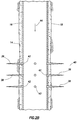
- the opening 68 is a perforation formed through a sidewall 70 of a tubular string 72 (such as, a casing, liner, tubing, etc.).
- a tubular string 72 such as, a casing, liner, tubing, etc.
- the opening 68 could be another type of opening, and may be formed in another type of structure.
- the device 60 is deployed into the tubular string 72 and is conveyed through the tubular string by fluid flow 74 .
- the fibers 62 of the device 60 enhance fluid drag on the device, so that the device is influenced to displace with the flow 74 .
- the device 60 Since the flow 74 (or a portion thereof) exits the tubular string 72 via the opening 68 , the device 60 will be influenced by the fluid drag to also exit the tubular string via the opening 68 .
- one set of the fibers 62 first enters the opening 68 , and the body 64 follows.
- the body 64 is appropriately dimensioned, so that it does not pass through the opening 68 , but instead is lodged or wedged into the opening.
- the body 64 may be received only partially in the opening 68 , and in other examples the body may be entirely received in the opening.
- the body 64 may completely or only partially block the flow 74 through the opening 68 . If the body 64 only partially blocks the flow 74 , any remaining fibers 62 exposed to the flow in the tubular string 72 can be carried by that flow into any gaps between the body and the opening 68 , so that a combination of the body and the fibers completely blocks flow through the opening.
- the device 60 may partially block flow through the opening 68 , and another material (such as, calcium carbonate, PLA or PGA particles) may be deployed and conveyed by the flow 74 into any gaps between the device and the opening, so that a combination of the device and the material completely blocks flow through the opening.
- another material such as, calcium carbonate, PLA or PGA particles
- the device 60 may permanently prevent flow through the opening 68 , or the device may degrade to eventually permit flow through the opening. If the device 60 degrades, it may be self-degrading, or it may be degraded in response to any of a variety of different stimuli. Any technique or means for degrading the device 60 (and any other material used in conjunction with the device to block flow through the opening 68 ) may be used in keeping with the scope of this disclosure.
- the device 60 may be used to block flow through openings in a well, with the device being uniquely configured so that its conveyance with the flow is enhanced.
- the method can comprise: a device 60 introduced into the well being conveyed by flow 74 in the well, and the device 60 comprising a plurality of fibers 62 extending outwardly from a body 64 .
- the method can include the body 64 engaging an opening 68 in the well.
- the opening 68 may comprise a perforation.
- the opening 68 could be in a valve, at a corrosion location, a point of leakage, etc.
- the body 64 can prevent flow through the opening 68 .
- the fibers 62 may be joined together and form one or more lines 66 extending outwardly from the body 64 .
- the lines 66 can comprise one or more ropes.
- the body 64 can comprise a fabric or cloth.
- the body 64 can comprise at least one knot.
- Other structures such as, spheres, oblong structures, etc. may be used in other examples.
- the body 64 can comprise a non-degradable or a degradable material.
- the body 64 may be self-degrading, or the body may degrade in response to application of a degrading treatment.
- the method can include the material degrading in response to at least one of: passage of a predetermined period of time in the well, exposure to a predetermined temperature in the well, exposure to a predetermined fluid in the well, exposure to radiation (e.g., electromagnetic, light or nuclear, such as gamma, beta, alpha or neutron particles), and exposure to a predetermined chemical composition in the well.
- radiation e.g., electromagnetic, light or nuclear, such as gamma, beta, alpha or neutron particles
- the method can include deploying the device 60 into the well after fracturing a formation zone 40 a,b .
- the device 60 may be deployed, and the formation zone 40 a,b may be fractured, during a single trip of a tubular string 12 into a well.
- single trip is used to indicate only a single deployment of a tubular string into a well.
- the tubular string may be retrieved from the well at a conclusion of the single trip, or the tubular string may not be retrieved from the well.
- the system 10 can comprise a flow conveyed device 60 conveyed through a tubular string 72 by flow 74 in the tubular string.
- the flow conveyed device 60 can comprise a body 64 with a plurality of fibers 62 extending outwardly from the body.
- the flow conveyed device 60 may engage an opening 68 in a sidewall 70 of the tubular string 72 . At least a portion of the fibers 62 can be conveyed into the opening 68 by flow 74 through the opening.
- the body 64 may extend across and seal off the opening 68 .
- the opening 68 can comprise a perforation. The scope of this disclosure is not limited to any particular type of opening.
- the device 60 can comprise a degradable body 64 , and a plurality of fibers 62 joined to the body. Each of the fibers 62 has a lateral dimension that is substantially smaller than a size of the body 64 .
- the body 64 may degrade in response to passage of a predetermined period of time, exposure to a predetermined fluid, exposure to a predetermined chemical composition, exposure to radiation (e.g., electromagnetic, light or nuclear, such as gamma, beta, alpha or neutron particles), and/or exposure to a predetermined temperature. In some examples, the body 64 may not be degradable.
- radiation e.g., electromagnetic, light or nuclear, such as gamma, beta, alpha or neutron particles
- the fibers 62 may comprise a nylon material.
- the fibers 62 can extend from one or more ropes, fabrics or cloths in some examples.
- the body 64 may be degradable by exposure to an acid.
Landscapes
- Engineering & Computer Science (AREA)
- Life Sciences & Earth Sciences (AREA)
- Geology (AREA)
- Mining & Mineral Resources (AREA)
- Environmental & Geological Engineering (AREA)
- Fluid Mechanics (AREA)
- General Life Sciences & Earth Sciences (AREA)
- Geochemistry & Mineralogy (AREA)
- Physics & Mathematics (AREA)
- Mechanical Engineering (AREA)
- Earth Drilling (AREA)
- Physical Or Chemical Processes And Apparatus (AREA)
- Pipe Accessories (AREA)
- Rigid Pipes And Flexible Pipes (AREA)
- Air Transport Of Granular Materials (AREA)
- Pressure Vessels And Lids Thereof (AREA)
- Biological Treatment Of Waste Water (AREA)
- Bulkheads Adapted To Foundation Construction (AREA)
- Sewage (AREA)
- Sealing Material Composition (AREA)
- Feeding, Discharge, Calcimining, Fusing, And Gas-Generation Devices (AREA)
Abstract
Description
Claims (13)
Priority Applications (77)
| Application Number | Priority Date | Filing Date | Title |
|---|---|---|---|
| US14/698,578 US10641069B2 (en) | 2015-04-28 | 2015-04-28 | Flow control in subterranean wells |
| AU2015393421A AU2015393421B2 (en) | 2015-04-28 | 2015-06-29 | Flow control in subterranean wells |
| CA2957681A CA2957681C (en) | 2015-04-28 | 2015-06-29 | Flow control in subterranean wells |
| MX2017001809A MX2017001809A (en) | 2015-04-28 | 2015-06-29 | Flow cotrol in subterranean wells. |
| US14/966,812 US9551204B2 (en) | 2015-04-28 | 2015-12-11 | Flow control in subterranean wells |
| US15/062,669 US9523267B2 (en) | 2015-04-28 | 2016-03-07 | Flow control in subterranean wells |
| CA2995533A CA2995533C (en) | 2015-04-28 | 2016-04-20 | Flow control in subterranean wells |
| CA2927918A CA2927918C (en) | 2015-04-28 | 2016-04-20 | Flow control in subterranean wells |
| AU2016202533A AU2016202533B2 (en) | 2015-04-28 | 2016-04-21 | Flow control in subterranean wells |
| MX2016005422A MX2016005422A (en) | 2015-04-28 | 2016-04-26 | Flow control in subterranean wells. |
| US15/567,779 US10655427B2 (en) | 2015-04-28 | 2016-04-26 | Flow control in subterranean wells |
| CA2928237A CA2928237C (en) | 2015-04-28 | 2016-04-26 | Fibrous barriers and deployment in subterranean wells |
| MX2016005409A MX2016005409A (en) | 2015-04-28 | 2016-04-26 | Plugging device deployment in subterranean wells. |
| US15/138,408 US9567826B2 (en) | 2015-04-28 | 2016-04-26 | Flow control in subterranean wells |
| AU2016202612A AU2016202612B2 (en) | 2015-04-28 | 2016-04-26 | Fibrous barriers and deployment in subterranean wells |
| MX2016005414A MX2016005414A (en) | 2015-04-28 | 2016-04-26 | Flow control in subterranean wells. |
| CA2928236A CA2928236C (en) | 2015-04-28 | 2016-04-26 | Flow control in subterranean wells |
| US15/138,968 US9745820B2 (en) | 2015-04-28 | 2016-04-26 | Plugging device deployment in subterranean wells |
| CA3177228A CA3177228A1 (en) | 2015-04-28 | 2016-04-26 | Flow control in subterranean wells |
| US15/138,378 US9567825B2 (en) | 2015-04-28 | 2016-04-26 | Flow control in subterranean wells |
| AU2016202619A AU2016202619B2 (en) | 2015-04-28 | 2016-04-26 | Flow control in subterranean wells |
| US15/138,449 US9708883B2 (en) | 2015-04-28 | 2016-04-26 | Flow control in subterranean wells |
| ARP160101167A AR104404A1 (en) | 2015-04-28 | 2016-04-26 | FLOW CONTROL IN UNDERGROUND WELLS |
| CA2928256A CA2928256C (en) | 2015-04-28 | 2016-04-26 | Flow control in subterranean wells |
| PCT/US2016/029314 WO2016176181A1 (en) | 2015-04-28 | 2016-04-26 | Flow control in subterranean wells |
| AU2016202624A AU2016202624B2 (en) | 2015-04-28 | 2016-04-26 | Plugging device deployment in subterranean wells |
| CA2992763A CA2992763C (en) | 2015-04-28 | 2016-04-26 | Fibrous barriers and deployment in subterranean wells |
| MX2016005420A MX2016005420A (en) | 2015-04-28 | 2016-04-26 | Flow control in subterranean wells. |
| AU2016202614A AU2016202614B2 (en) | 2015-04-28 | 2016-04-26 | Flow control in subterranean wells |
| ARP160101171A AR104408A1 (en) | 2015-04-28 | 2016-04-26 | FLOW CONTROL IN UNDERGROUND WELLS |
| CA2928257A CA2928257C (en) | 2015-04-28 | 2016-04-26 | Plugging device deployment in subterranean wells |
| ARP160101165A AR104402A1 (en) | 2015-04-28 | 2016-04-26 | FIBROSO BARRIERS AND DEPLOYMENT IN UNDERGROUND WELLS |
| AU2016202620A AU2016202620A1 (en) | 2015-04-28 | 2016-04-26 | Flow control in subterranean wells |
| US15/138,327 US9567824B2 (en) | 2015-04-28 | 2016-04-26 | Fibrous barriers and deployment in subterranean wells |
| AU2016202616A AU2016202616B2 (en) | 2015-04-28 | 2016-04-26 | Flow control in subterranean wells |
| MX2017013752A MX2017013752A (en) | 2015-04-28 | 2016-04-26 | Flow control in subterranean wells. |
| CA2928245A CA2928245C (en) | 2015-04-28 | 2016-04-26 | Flow control in subterranean wells |
| MX2016005411A MX2016005411A (en) | 2015-04-28 | 2016-04-26 | Fibrous barriers and deployment in subterranean wells. |
| ARP160101170A AR104407A1 (en) | 2015-04-28 | 2016-04-26 | FLOW CONTROL IN UNDERGROUND WELLS |
| ARP160101166A AR104403A1 (en) | 2015-04-28 | 2016-04-26 | FLOW CONTROL IN UNDERGROUND WELLS |
| MX2016005410A MX2016005410A (en) | 2015-04-28 | 2016-04-26 | Flow control in subterranean wells. |
| CA2928239A CA2928239C (en) | 2015-04-28 | 2016-04-26 | Flow control in subterranean wells |
| ARP160101169A AR104406A1 (en) | 2015-04-28 | 2016-04-26 | TREATMENT DEVICE TRANSPORTED WITH THE FLOW FOR USE IN A UNDERGROUND WELL |
| US15/138,685 US10233719B2 (en) | 2015-04-28 | 2016-04-26 | Flow control in subterranean wells |
| MX2016005421A MX2016005421A (en) | 2015-04-28 | 2016-04-26 | Flow control in subterranean wells. |
| CA2983253A CA2983253C (en) | 2015-04-28 | 2016-04-26 | Flow control in subterranean wells |
| ARP160101172A AR104409A1 (en) | 2015-04-28 | 2016-04-26 | DEPLOYMENT OF OBTURATION DEVICE IN UNDERGROUND WELLS |
| ARP160101164A AR104401A1 (en) | 2015-04-28 | 2016-04-26 | METHOD FOR CONTROLLING THE FLOW IN A UNDERGROUND WELL |
| AU2016256383A AU2016256383B2 (en) | 2015-04-28 | 2016-04-26 | Flow control in subterranean wells |
| ARP160101216A AR104446A1 (en) | 2015-04-28 | 2016-04-28 | FLOW CONTROL IN UNDERGROUND WELLS |
| US15/296,342 US9816341B2 (en) | 2015-04-28 | 2016-10-18 | Plugging devices and deployment in subterranean wells |
| US15/347,535 US10641070B2 (en) | 2015-04-28 | 2016-11-09 | Flow control in subterranean wells |
| US15/391,014 US10738566B2 (en) | 2015-04-28 | 2016-12-27 | Flow control in subterranean wells |
| US15/390,941 US10738564B2 (en) | 2015-04-28 | 2016-12-27 | Fibrous barriers and deployment in subterranean wells |
| US15/390,976 US10738565B2 (en) | 2015-04-28 | 2016-12-27 | Flow control in subterranean wells |
| US15/609,671 US10851615B2 (en) | 2015-04-28 | 2017-05-31 | Flow control in subterranean wells |
| US15/615,136 US10774612B2 (en) | 2015-04-28 | 2017-06-06 | Flow control in subterranean wells |
| US15/622,016 US10513653B2 (en) | 2015-04-28 | 2017-06-13 | Flow control in subterranean wells |
| US15/658,697 US11002106B2 (en) | 2015-04-28 | 2017-07-25 | Plugging device deployment in subterranean wells |
| AU2017216597A AU2017216597B2 (en) | 2015-04-28 | 2017-08-18 | Flow control in subterranean wells |
| AU2017218948A AU2017218948B2 (en) | 2015-04-28 | 2017-08-21 | Fibrous barriers and deployment in subterranean wells |
| AU2017219082A AU2017219082B2 (en) | 2015-04-28 | 2017-08-25 | Flow control in subterranean wells |
| AU2017219089A AU2017219089B2 (en) | 2015-04-28 | 2017-08-25 | Flow control in subterranean wells |
| US15/726,160 US10513902B2 (en) | 2015-04-28 | 2017-10-05 | Plugging devices and deployment in subterranean wells |
| AU2017276220A AU2017276220B2 (en) | 2015-04-28 | 2017-12-13 | Flow control in subterranean wells |
| AU2017279758A AU2017279758B2 (en) | 2015-04-28 | 2017-12-21 | Flow control in subterranean wells |
| US16/214,174 US10641057B2 (en) | 2015-04-28 | 2018-12-10 | Flow control in subterranean wells |
| US16/238,838 US10767442B2 (en) | 2015-04-28 | 2019-01-03 | Flow control in subterranean wells |
| US16/264,758 US10900312B2 (en) | 2015-04-28 | 2019-02-01 | Plugging devices and deployment in subterranean wells |
| US16/264,766 US10907430B2 (en) | 2015-04-28 | 2019-02-01 | Plugging devices and deployment in subterranean wells |
| AU2019201177A AU2019201177B2 (en) | 2015-04-28 | 2019-02-20 | Flow control in subterranean wells |
| AU2019219723A AU2019219723B2 (en) | 2015-04-28 | 2019-08-19 | Flow control in subterranean wells |
| US16/597,183 US11427751B2 (en) | 2015-04-28 | 2019-10-09 | Flow control in subterranean wells |
| US16/987,094 US11242727B2 (en) | 2015-04-28 | 2020-08-06 | Flow control in subterranean wells |
| AU2020256342A AU2020256342B2 (en) | 2015-04-28 | 2020-10-13 | Flow control in subterranean wells |
| ARP200103245A AR120535A2 (en) | 2015-04-28 | 2020-11-20 | FIBROUS BARRIERS AND DEPLOYMENT IN UNDERGROUND WELLS |
| US17/813,359 US11851611B2 (en) | 2015-04-28 | 2022-07-19 | Flow control in subterranean wells |
Applications Claiming Priority (1)
| Application Number | Priority Date | Filing Date | Title |
|---|---|---|---|
| US14/698,578 US10641069B2 (en) | 2015-04-28 | 2015-04-28 | Flow control in subterranean wells |
Related Parent Applications (2)
| Application Number | Title | Priority Date | Filing Date |
|---|---|---|---|
| PCT/US2015/038248 Continuation-In-Part WO2016175876A1 (en) | 2015-04-28 | 2015-06-29 | Flow cotrol in subterranean wells |
| US15/347,535 Continuation-In-Part US10641070B2 (en) | 2015-04-28 | 2016-11-09 | Flow control in subterranean wells |
Related Child Applications (14)
| Application Number | Title | Priority Date | Filing Date |
|---|---|---|---|
| PCT/US2015/038248 Continuation-In-Part WO2016175876A1 (en) | 2015-04-28 | 2015-06-29 | Flow cotrol in subterranean wells |
| US14/966,812 Continuation US9551204B2 (en) | 2015-04-28 | 2015-12-11 | Flow control in subterranean wells |
| US15/062,699 Continuation-In-Part US9569573B1 (en) | 2015-10-27 | 2016-03-07 | RAS evaluation for circuit element |
| US15/062,669 Continuation-In-Part US9523267B2 (en) | 2015-04-28 | 2016-03-07 | Flow control in subterranean wells |
| US15/138,327 Continuation-In-Part US9567824B2 (en) | 2015-04-28 | 2016-04-26 | Fibrous barriers and deployment in subterranean wells |
| PCT/US2016/029314 Continuation-In-Part WO2016176181A1 (en) | 2015-04-28 | 2016-04-26 | Flow control in subterranean wells |
| US15/138,378 Continuation-In-Part US9567825B2 (en) | 2015-04-28 | 2016-04-26 | Flow control in subterranean wells |
| US15/138,968 Continuation-In-Part US9745820B2 (en) | 2015-04-28 | 2016-04-26 | Plugging device deployment in subterranean wells |
| US15/138,408 Continuation-In-Part US9567826B2 (en) | 2015-04-28 | 2016-04-26 | Flow control in subterranean wells |
| US15/138,449 Continuation-In-Part US9708883B2 (en) | 2015-04-28 | 2016-04-26 | Flow control in subterranean wells |
| US15/567,779 Continuation-In-Part US10655427B2 (en) | 2015-04-28 | 2016-04-26 | Flow control in subterranean wells |
| US15/138,685 Continuation-In-Part US10233719B2 (en) | 2015-04-28 | 2016-04-26 | Flow control in subterranean wells |
| US15/347,535 Continuation-In-Part US10641070B2 (en) | 2015-04-28 | 2016-11-09 | Flow control in subterranean wells |
| US15/615,136 Continuation-In-Part US10774612B2 (en) | 2015-04-28 | 2017-06-06 | Flow control in subterranean wells |
Publications (2)
| Publication Number | Publication Date |
|---|---|
| US20160319628A1 US20160319628A1 (en) | 2016-11-03 |
| US10641069B2 true US10641069B2 (en) | 2020-05-05 |
Family
ID=57204616
Family Applications (3)
| Application Number | Title | Priority Date | Filing Date |
|---|---|---|---|
| US14/698,578 Active 2037-05-04 US10641069B2 (en) | 2015-04-28 | 2015-04-28 | Flow control in subterranean wells |
| US14/966,812 Active US9551204B2 (en) | 2015-04-28 | 2015-12-11 | Flow control in subterranean wells |
| US15/347,535 Active 2037-01-27 US10641070B2 (en) | 2015-04-28 | 2016-11-09 | Flow control in subterranean wells |
Family Applications After (2)
| Application Number | Title | Priority Date | Filing Date |
|---|---|---|---|
| US14/966,812 Active US9551204B2 (en) | 2015-04-28 | 2015-12-11 | Flow control in subterranean wells |
| US15/347,535 Active 2037-01-27 US10641070B2 (en) | 2015-04-28 | 2016-11-09 | Flow control in subterranean wells |
Country Status (5)
| Country | Link |
|---|---|
| US (3) | US10641069B2 (en) |
| AR (10) | AR104404A1 (en) |
| AU (4) | AU2015393421B2 (en) |
| CA (3) | CA2957681C (en) |
| MX (2) | MX2017001809A (en) |
Cited By (9)
| Publication number | Priority date | Publication date | Assignee | Title |
|---|---|---|---|---|
| US20190162034A1 (en) * | 2015-04-28 | 2019-05-30 | Thru Tubing Solutions, Inc. | Plugging devices and deployment in subterranean wells |
| US10851615B2 (en) | 2015-04-28 | 2020-12-01 | Thru Tubing Solutions, Inc. | Flow control in subterranean wells |
| US11002106B2 (en) * | 2015-04-28 | 2021-05-11 | Thru Tubing Solutions, Inc. | Plugging device deployment in subterranean wells |
| US11242727B2 (en) * | 2015-04-28 | 2022-02-08 | Thru Tubing Solutions, Inc. | Flow control in subterranean wells |
| US11377926B2 (en) | 2015-07-21 | 2022-07-05 | Thru Tubing Solutions, Inc. | Plugging device deployment |
| US20220235622A1 (en) * | 2016-12-13 | 2022-07-28 | Thru Tubing Solutions, Inc. | Methods of completing a well and apparatus therefor |
| US11427751B2 (en) * | 2015-04-28 | 2022-08-30 | Thru Tubing Solutions, Inc. | Flow control in subterranean wells |
| US20220348819A1 (en) * | 2015-04-28 | 2022-11-03 | Thru Tubing Solutions, Inc. | Flow control in subterranean wells |
| US11761295B2 (en) | 2015-07-21 | 2023-09-19 | Thru Tubing Solutions, Inc. | Plugging device deployment |
Families Citing this family (24)
| Publication number | Priority date | Publication date | Assignee | Title |
|---|---|---|---|---|
| US10036229B2 (en) * | 2015-02-13 | 2018-07-31 | Weatherford Technology Holdings, Llc | Time delay toe sleeve |
| US10655427B2 (en) | 2015-04-28 | 2020-05-19 | Thru Tubing Solutions, Inc. | Flow control in subterranean wells |
| US10641069B2 (en) | 2015-04-28 | 2020-05-05 | Thru Tubing Solutions, Inc. | Flow control in subterranean wells |
| US10233719B2 (en) | 2015-04-28 | 2019-03-19 | Thru Tubing Solutions, Inc. | Flow control in subterranean wells |
| US9567826B2 (en) | 2015-04-28 | 2017-02-14 | Thru Tubing Solutions, Inc. | Flow control in subterranean wells |
| US9567825B2 (en) | 2015-04-28 | 2017-02-14 | Thru Tubing Solutions, Inc. | Flow control in subterranean wells |
| US9567824B2 (en) | 2015-04-28 | 2017-02-14 | Thru Tubing Solutions, Inc. | Fibrous barriers and deployment in subterranean wells |
| US20170159404A1 (en) * | 2015-11-25 | 2017-06-08 | Frederic D. Sewell | Hydraulic Fracturing with Strong, Lightweight, Low Profile Diverters |
| US10815750B2 (en) * | 2015-11-25 | 2020-10-27 | Frederic D. Sewell | Hydraulic fracturing with strong, lightweight, low profile diverters |
| US9920589B2 (en) | 2016-04-06 | 2018-03-20 | Thru Tubing Solutions, Inc. | Methods of completing a well and apparatus therefor |
| US9903191B2 (en) | 2016-07-12 | 2018-02-27 | Leon Marmorshteyn | Method of increasing productivity of oil and gas recovery from previously used wells |
| WO2018200698A1 (en) | 2017-04-25 | 2018-11-01 | Thru Tubing Solutions, Inc. | Plugging undesired openings in fluid conduits |
| CA3058511C (en) | 2017-04-25 | 2022-08-23 | Thru Tubing Solutions, Inc. | Plugging undesired openings in fluid vessels |
| WO2018204655A1 (en) | 2017-05-03 | 2018-11-08 | Coil Solutions, Inc. | Extended reach tool |
| US20190120004A1 (en) * | 2017-10-24 | 2019-04-25 | Baker Hughes, A Ge Company, Llc | Borehole Alteration of Tubular String to Create and Close Off Openings |
| WO2020081621A1 (en) * | 2018-10-18 | 2020-04-23 | Terves Llc | Degradable deformable diverters and seals |
| US10871049B2 (en) | 2019-02-05 | 2020-12-22 | Thru Tubing Solutions, Inc. | Well operations with grouped particle diverter plug |
| US11585173B2 (en) | 2019-12-02 | 2023-02-21 | Thru Tubing Solutions, Inc. | Fluid flow control during well treatment |
| US11519240B2 (en) | 2019-12-02 | 2022-12-06 | Thru Tubing Solutions, Inc. | Fluid flow control during well treatment |
| CN111485852B (en) * | 2020-04-27 | 2022-07-05 | 中国石油天然气股份有限公司 | Oil-gas well casing liquid resin plugging squeezing tool and construction process |
| CN112360388A (en) * | 2020-11-09 | 2021-02-12 | 内蒙古浦景聚合材料科技有限公司 | Self-adaptive degradable material suitable for temporary plugging fracturing operation of underground reservoir |
| CN112696184B (en) * | 2021-03-24 | 2021-06-22 | 四川省威沃敦化工有限公司 | Fracturing construction method for oil and gas well |
| CN115612468B (en) * | 2022-09-21 | 2023-11-10 | 中国石油化工股份有限公司 | Rope knot temporary blocking ball and preparation method and application thereof |
| CN115614018B (en) * | 2022-12-21 | 2023-06-20 | 四川省威沃敦石油科技股份有限公司 | Temporary plugging staged fracturing construction method for biological junction of sleeve-type variable well |
Citations (136)
| Publication number | Priority date | Publication date | Assignee | Title |
|---|---|---|---|---|
| US2157493A (en) | 1938-04-29 | 1939-05-09 | Miller Melvin | Well scraper |
| US2621351A (en) | 1948-08-30 | 1952-12-16 | Phillips Petroleum Co | Apparatus for forcibly propelling pellets against a surface |
| US2754910A (en) * | 1955-04-27 | 1956-07-17 | Chemical Process Company | Method of temporarily closing perforations in the casing |
| US2768693A (en) | 1954-08-06 | 1956-10-30 | Jr James R Hughes | Method of preventing the loss of drilling mud |
| US2788072A (en) | 1952-02-13 | 1957-04-09 | Pan American Petroleum Corp | Method of fracturing a well formation |
| US2838117A (en) | 1953-05-22 | 1958-06-10 | Pan American Petroleum Corp | Fracturing formations at selected elevations |
| US2970645A (en) | 1957-03-06 | 1961-02-07 | Pan American Petroleum Corp | Producing multiple fractures in a well |
| US3011548A (en) | 1958-07-28 | 1961-12-05 | Clarence B Holt | Apparatus for method for treating wells |
| US3028914A (en) | 1958-09-29 | 1962-04-10 | Pan American Petroleum Corp | Producing multiple fractures in a cased well |
| US3170517A (en) | 1962-11-13 | 1965-02-23 | Jersey Prod Res Co | Fracturing formation and stimulation of wells |
| US3174546A (en) | 1962-08-29 | 1965-03-23 | Pan American Petroleum Corp | Method for selectively sealing-off formations |
| US3292700A (en) | 1964-03-02 | 1966-12-20 | William B Berry | Method and apparatus for sealing perforations in a well casing |
| US3376934A (en) * | 1965-11-19 | 1968-04-09 | Exxon Production Research Co | Perforation sealer |
| US3399726A (en) | 1966-05-23 | 1968-09-03 | Gulf Research Development Co | Method of plugging perforations in casings |
| US3417821A (en) | 1966-06-08 | 1968-12-24 | Halliburton Co | Fluid loss control |
| US3434539A (en) | 1967-03-06 | 1969-03-25 | Byron Jackson Inc | Plugs for use in treating wells with liquids |
| US3437147A (en) * | 1967-02-23 | 1969-04-08 | Mobil Oil Corp | Method and apparatus for plugging well pipe perforations |
| US3595314A (en) | 1970-06-02 | 1971-07-27 | Cities Service Oil Co | Apparatus for selectively plugging portions of a perforated zone |
| US3707194A (en) | 1971-07-13 | 1972-12-26 | Marathon Oil Co | Use of diverting agents for injection well stimulation |
| US3814187A (en) | 1973-05-14 | 1974-06-04 | Amoco Prod Co | Subsurface formation plugging |
| US3895678A (en) | 1974-07-08 | 1975-07-22 | Dresser Ind | Sealer ball catcher and method of use thereof |
| US4187909A (en) | 1977-11-16 | 1980-02-12 | Exxon Production Research Company | Method and apparatus for placing buoyant ball sealers |
| US4194561A (en) | 1977-11-16 | 1980-03-25 | Exxon Production Research Company | Placement apparatus and method for low density ball sealers |
| US4244425A (en) | 1979-05-03 | 1981-01-13 | Exxon Production Research Company | Low density ball sealers for use in well treatment fluid diversions |
| US4505334A (en) | 1983-09-06 | 1985-03-19 | Oil States Industries, Inc. | Ball sealer |
| US4628994A (en) | 1984-05-15 | 1986-12-16 | Texaust Australia Limited | Oil wells |
| US4716964A (en) | 1981-08-10 | 1988-01-05 | Exxon Production Research Company | Use of degradable ball sealers to seal casing perforations in well treatment fluid diversion |
| US4921577A (en) | 1988-08-02 | 1990-05-01 | Eubank Dennis R | Method for operating a well to remove production limiting or flow restrictive material |
| US4924811A (en) * | 1988-11-30 | 1990-05-15 | Axelrod Herbert R | Therapeutic device for cleaning the teeth of dogs |
| US5004048A (en) | 1989-11-15 | 1991-04-02 | Bode Robert E | Apparatus for injecting displacement plugs |
| WO1991011587A1 (en) | 1990-01-29 | 1991-08-08 | Conoco Inc. | Method and apparatus for sealing pipe perforations |
| US5052489A (en) | 1990-06-15 | 1991-10-01 | Carisella James V | Apparatus for selectively actuating well tools |
| US5052220A (en) | 1989-10-17 | 1991-10-01 | Schlumberger Technology Corporation | Apparatus for measurements related to fluid flow in a borehole |
| US5253709A (en) | 1990-01-29 | 1993-10-19 | Conoco Inc. | Method and apparatus for sealing pipe perforations |
| US5456317A (en) | 1989-08-31 | 1995-10-10 | Union Oil Co | Buoyancy assisted running of perforated tubulars |
| US5477815A (en) * | 1992-08-20 | 1995-12-26 | Booda Products, Inc. | Dog chew toy |
| US5507345A (en) | 1994-11-23 | 1996-04-16 | Chevron U.S.A. Inc. | Methods for sub-surface fluid shut-off |
| US5908073A (en) * | 1997-06-26 | 1999-06-01 | Halliburton Energy Services, Inc. | Preventing well fracture proppant flow-back |
| US6070666A (en) | 1998-04-30 | 2000-06-06 | Atlantic Richfield Company | Fracturing method for horizontal wells |
| US20020007949A1 (en) | 2000-07-18 | 2002-01-24 | Tolman Randy C. | Method for treating multiple wellbore intervals |
| US6394184B2 (en) | 2000-02-15 | 2002-05-28 | Exxonmobil Upstream Research Company | Method and apparatus for stimulation of multiple formation intervals |
| US6427776B1 (en) | 2000-03-27 | 2002-08-06 | Weatherford/Lamb, Inc. | Sand removal and device retrieval tool |
| US6655475B1 (en) | 2001-01-23 | 2003-12-02 | H. Lester Wald | Product and method for treating well bores |
| US20040129460A1 (en) | 2002-08-01 | 2004-07-08 | Macquoid Malcolm | Method for using coconut coir as a lost circulation material for well drilling |
| US20040261990A1 (en) | 2001-07-18 | 2004-12-30 | Bosma Martin Gerard Rene | Wellbore system with annular seal member |
| US20050184083A1 (en) | 2004-02-24 | 2005-08-25 | Diaz Juan M. | Remote actuator for ball injector |
| US20050230117A1 (en) | 2004-04-16 | 2005-10-20 | Wilkinson Jeffrey M | Method of treating oil and gas wells |
| US6973966B2 (en) | 2003-11-14 | 2005-12-13 | Halliburton Energy Services, Inc. | Compressible darts and methods for using these darts in subterranean wells |
| US20060102336A1 (en) | 2004-11-12 | 2006-05-18 | Tony Campbell | Primary electro-mechanical initiating dump bailer device and method of use |
| US20060169449A1 (en) | 2005-01-31 | 2006-08-03 | Halliburton Energy Services, Inc. | Self-degrading fibers and associated methods of use and manufacture |
| US20060213662A1 (en) | 2005-03-25 | 2006-09-28 | Creel Prentice G | Methods of delivering material downhole |
| US20070039739A1 (en) | 2003-07-30 | 2007-02-22 | Conocophillips Company | Well chemical treatment utilizing plunger lift delivery system with chemically improved plunger seal |
| US7225869B2 (en) | 2004-03-24 | 2007-06-05 | Halliburton Energy Services, Inc. | Methods of isolating hydrajet stimulated zones |
| WO2007066254A2 (en) | 2005-12-05 | 2007-06-14 | Schlumberger Canada Limited | Degradable material assisted diversion or isolation |
| US20070169935A1 (en) | 2005-12-19 | 2007-07-26 | Fairmount Minerals, Ltd. | Degradable ball sealers and methods for use in well treatment |
| US20070187099A1 (en) | 2006-02-10 | 2007-08-16 | Ling Wang | Methods and Compositions for Sealing Fractures, Voids, and Pores of Subterranean Rock Formations |
| US7273099B2 (en) | 2004-12-03 | 2007-09-25 | Halliburton Energy Services, Inc. | Methods of stimulating a subterranean formation comprising multiple production intervals |
| US20080093073A1 (en) | 2006-10-24 | 2008-04-24 | Oscar Bustos | Degradable Material Assisted Diversion |
| US20080128133A1 (en) | 2006-12-05 | 2008-06-05 | Turley Rocky A | Wellbore plug adapter kit |
| US20080200352A1 (en) | 2004-09-01 | 2008-08-21 | Willberg Dean M | Degradable Material Assisted Diversion or Isolation |
| US20080196896A1 (en) | 2007-02-15 | 2008-08-21 | Oscar Bustos | Methods and apparatus for fiber-based diversion |
| US7527095B2 (en) | 2003-12-11 | 2009-05-05 | Shell Oil Company | Method of creating a zonal isolation in an underground wellbore |
| US7559363B2 (en) | 2007-01-05 | 2009-07-14 | Halliburton Energy Services, Inc. | Wiper darts for subterranean operations |
| US7571773B1 (en) | 2008-04-17 | 2009-08-11 | Baker Hughes Incorporated | Multiple ball launch assemblies and methods of launching multiple balls into a wellbore |
| US7624810B2 (en) | 2007-12-21 | 2009-12-01 | Schlumberger Technology Corporation | Ball dropping assembly and technique for use in a well |
| US7673688B1 (en) | 2008-09-09 | 2010-03-09 | Halliburton Energy Services, Inc. | Casing wiping dart with filtering layer |
| US7673673B2 (en) | 2007-08-03 | 2010-03-09 | Halliburton Energy Services, Inc. | Apparatus for isolating a jet forming aperture in a well bore servicing tool |
| US20100122813A1 (en) | 2008-11-18 | 2010-05-20 | Sascha Trummer | Method of Placing Ball Sealers For Fluid Diversion |
| US20100152070A1 (en) * | 2008-12-11 | 2010-06-17 | Jaleh Ghassemzadeh | Drilling lost circulation material |
| US20100147866A1 (en) | 2008-12-15 | 2010-06-17 | Weir Spm, Inc. | Ball Injector |
| US7748452B2 (en) | 2008-02-19 | 2010-07-06 | Schlumberger Technology Corporation | Polymeric microspheres as degradable fluid loss additives in oilfield applications |
| US20100175889A1 (en) | 2009-01-09 | 2010-07-15 | Owen Oil Tools Lp | Detonator for Material-Dispensing Wellbore Tools |
| US20100200235A1 (en) | 2009-02-11 | 2010-08-12 | Halliburton Energy Services, Inc. | Degradable perforation balls and associated methods of use in subterranean applications |
| US7810567B2 (en) | 2007-06-27 | 2010-10-12 | Schlumberger Technology Corporation | Methods of producing flow-through passages in casing, and methods of using such casing |
| US20100307747A1 (en) | 2009-06-05 | 2010-12-09 | Nikhil Shindgikar | Engineered fibers for well treatments |
| US7874365B2 (en) | 2006-06-09 | 2011-01-25 | Halliburton Energy Services Inc. | Methods and devices for treating multiple-interval well bores |
| US20110048712A1 (en) | 2009-08-27 | 2011-03-03 | Phil Barbee | Method and apparatus for dropping a pump down plug or ball |
| US20110226479A1 (en) | 2008-04-15 | 2011-09-22 | Philipp Tippel | Diversion by combining dissolvable and degradable particles and fibers |
| US20110297396A1 (en) | 2010-06-02 | 2011-12-08 | Hendel Rudolf H | Enhanced hydrocarbon well blowout protection |
| US8088717B2 (en) | 2004-06-17 | 2012-01-03 | Exxonmobil Upstream Research Company | Compressible objects having partial foam interiors combined with a drilling fluid to form a variable density drilling mud |
| US20120013893A1 (en) | 2010-07-19 | 2012-01-19 | Halliburton Energy Services, Inc. | Communication through an enclosure of a line |
| US20120031614A1 (en) | 2010-08-04 | 2012-02-09 | Joel Rondeau | Apparatus and methods for well cementing |
| US20120085548A1 (en) | 2010-10-06 | 2012-04-12 | Colorado School Of Mines | Downhole Tools and Methods for Selectively Accessing a Tubular Annulus of a Wellbore |
| US20120090835A1 (en) | 2010-10-13 | 2012-04-19 | Slaheddine Kefi | Downhole material-delivery system for subterranean wells |
| US20120181032A1 (en) * | 2011-01-14 | 2012-07-19 | Utex Industries, Inc. | Disintegrating ball for sealing frac plug seat |
| US8240392B2 (en) | 2009-09-23 | 2012-08-14 | Baker Hughes Incorporated | Use of foam shape memory polymer to transport acid or other wellbore treatments |
| US20120211219A1 (en) | 2011-02-22 | 2012-08-23 | Stinger Wellhead Protection, Inc. | Horizontal frac ball injector |
| US20120234538A1 (en) | 2011-03-14 | 2012-09-20 | General Plastics & Composites, Lp | Composite frac ball |
| US8281860B2 (en) | 2006-08-25 | 2012-10-09 | Schlumberger Technology Corporation | Method and system for treating a subterranean formation |
| US8307916B1 (en) | 2007-02-27 | 2012-11-13 | Wald H Lester | Controlling fluid loss in oil and gas wells |
| US20120285659A1 (en) | 2010-01-14 | 2012-11-15 | Woongjin Coway Co., Ltd. | Heat exchanger, a food handler including the heat exchanger, and a manufacturing method of the heat exchanger |
| US20120285695A1 (en) * | 2011-05-11 | 2012-11-15 | Schlumberger Technology Corporation | Destructible containers for downhole material and chemical delivery |
| US20130062055A1 (en) | 2010-05-26 | 2013-03-14 | Randy C. Tolman | Assembly and method for multi-zone fracture stimulation of a reservoir using autonomous tubular units |
| US8397820B2 (en) | 2001-11-19 | 2013-03-19 | Packers Plus Energy Services Inc. | Method and apparatus for wellbore fluid treatment |
| US20130098600A1 (en) | 2011-10-25 | 2013-04-25 | Team Oil Tools Lp | Manufacturing Technique for a Composite Ball for Use Downhole in a Hydrocarbon Wellbore |
| US20130186632A1 (en) | 2012-01-19 | 2013-07-25 | Gary Joe Makowiecki | Methods and apparatuses for wiping subterranean casings |
| US20130292123A1 (en) * | 2009-02-11 | 2013-11-07 | Halliburton Energy Services, Inc. | Degradable Balls for Use in Subterranean Applications |
| US8596362B2 (en) | 2011-05-19 | 2013-12-03 | Baker Hughes Incorporated | Hydraulic fracturing methods and well casing plugs |
| WO2013184238A1 (en) | 2012-06-06 | 2013-12-12 | Exxonmobil Upstream Research Company | Systems and methods for secondary sealing of a perforation within a wellbore casing |
| US20130327528A1 (en) | 2012-01-06 | 2013-12-12 | Odessa Separator, Inc. | Downhole Assembly for Treating Wellbore Components, and Method for Treating a Wellbore |
| US8646529B2 (en) | 2006-06-28 | 2014-02-11 | Schlumberger Technology Corporation | Method and system for treating a subterranean formation using diversion |
| WO2014042552A1 (en) | 2012-09-13 | 2014-03-20 | Schlumberger, Canada Limited | Shapeable particles in oilfield fluids |
| US20140116712A1 (en) | 2012-10-26 | 2014-05-01 | Weatherford/Lamb, Inc. | Deburring mill tool for wellbore cleaning |
| US20140151052A1 (en) | 2011-06-20 | 2014-06-05 | Packers Plus Energy Services Inc. | Kobe sub with inflow control, wellbore tubing string and method |
| WO2014099206A1 (en) | 2012-12-21 | 2014-06-26 | Exxonmobil Upstream Research Company | Flow control assemblies for downhole operations and systems and methods inclucding the same |
| US8776886B2 (en) | 2008-12-22 | 2014-07-15 | Schlumberger Technology Corporation | Apparatus and method for launching plugs in cementing operations |
| US20140231086A1 (en) | 2013-02-19 | 2014-08-21 | Halliburton Energy Services, Inc | Methods and compositions for treating subterranean formations with swellable lost circulation materials |
| US20140274815A1 (en) | 2013-03-15 | 2014-09-18 | Forta Corporation | Modified deformed reinforcement fibers, methods of making, and uses |
| US8851172B1 (en) | 2009-08-12 | 2014-10-07 | Parker-Hannifin Corporation | High strength, low density metal matrix composite ball sealer |
| US8853137B2 (en) | 2009-07-30 | 2014-10-07 | Halliburton Energy Services, Inc. | Increasing fracture complexity in ultra-low permeable subterranean formation using degradable particulate |
| US8887803B2 (en) | 2012-04-09 | 2014-11-18 | Halliburton Energy Services, Inc. | Multi-interval wellbore treatment method |
| US8950438B2 (en) | 2009-04-16 | 2015-02-10 | Brinker Technology Ltd | Method and compositions for delivery of a concentrated quantity of sealing elements to a leak site in a vessel |
| US20150060072A1 (en) | 2013-08-29 | 2015-03-05 | Schlumberger Technology Corporation | Methods of treatment of a subterranean formation with composite polymeric structures formed in situ |
| US20150075793A1 (en) | 2013-09-13 | 2015-03-19 | TD Tools, Inc. | Apparatus and method for jet perforating and cutting tool |
| US20150083423A1 (en) | 2011-11-22 | 2015-03-26 | Baker Hughes Incorporated | Method for improving isolation of flow to completed perforated intervals |
| US20150122364A1 (en) | 2013-07-31 | 2015-05-07 | Elwha Llc | Systems and methods for pipeline device propulsion |
| US20150191988A1 (en) | 2014-01-09 | 2015-07-09 | Quantum Composites, Inc. | Subterranean barrier, system and method of use |
| US20150240583A1 (en) | 2012-09-27 | 2015-08-27 | Halliburton Energy Services | Powered Wellbore Bailer |
| US9187975B2 (en) | 2012-10-26 | 2015-11-17 | Weatherford Technology Holdings, Llc | Filament wound composite ball |
| US20160040520A1 (en) | 2011-05-26 | 2016-02-11 | Randy C. Tolman | Methods for multi-zone fracture stimulation of a well |
| US20160130933A1 (en) | 2014-05-02 | 2016-05-12 | Halliburton Energy Services, Inc. | Computational Model for Tracking Ball Sealers in a Wellbore |
| US20160251930A1 (en) | 2015-02-27 | 2016-09-01 | Schlumberger Technology Corporation | Technique and apparatus for using an untethered object to form a seal in a well |
| US9523267B2 (en) | 2015-04-28 | 2016-12-20 | Thru Tubing Solutions, Inc. | Flow control in subterranean wells |
| US9551204B2 (en) | 2015-04-28 | 2017-01-24 | Thru Tubing Solutions, Inc. | Flow control in subterranean wells |
| US20170030169A1 (en) | 2015-04-28 | 2017-02-02 | Thru Tubing Solutions, Inc. | Plugging devices and deployment in subterranean wells |
| US9567824B2 (en) | 2015-04-28 | 2017-02-14 | Thru Tubing Solutions, Inc. | Fibrous barriers and deployment in subterranean wells |
| US9567826B2 (en) | 2015-04-28 | 2017-02-14 | Thru Tubing Solutions, Inc. | Flow control in subterranean wells |
| US9567825B2 (en) | 2015-04-28 | 2017-02-14 | Thru Tubing Solutions, Inc. | Flow control in subterranean wells |
| US9708883B2 (en) | 2015-04-28 | 2017-07-18 | Thru Tubing Solutions, Inc. | Flow control in subterranean wells |
| US9745820B2 (en) | 2015-04-28 | 2017-08-29 | Thru Tubing Solutions, Inc. | Plugging device deployment in subterranean wells |
| US20170260828A1 (en) | 2015-04-28 | 2017-09-14 | Thru Tubing Solutions, Inc. | Flow control in subterranean wells |
| US20170275961A1 (en) | 2015-04-28 | 2017-09-28 | Thru Tubing Solutions, Inc. | Flow control in subterranean wells |
| US20170275965A1 (en) | 2015-04-28 | 2017-09-28 | Thru Tubing Solutions, Inc. | Flow control in subterranean wells |
| US9920589B2 (en) | 2016-04-06 | 2018-03-20 | Thru Tubing Solutions, Inc. | Methods of completing a well and apparatus therefor |
| US20180135394A1 (en) | 2016-11-15 | 2018-05-17 | Randy C. Tolman | Wellbore Tubulars Including Selective Stimulation Ports Sealed with Sealing Devices and Methods of Operating the Same |
| US20180245439A1 (en) | 2017-02-24 | 2018-08-30 | Pavlin B. Entchev | Methods for Refracturing a Subterranean Formation Using Shearable Ball Seats for Zone Isolation |
Family Cites Families (14)
| Publication number | Priority date | Publication date | Assignee | Title |
|---|---|---|---|---|
| US2109058A (en) | 1936-10-10 | 1938-02-22 | John F Blee | Cementing plug |
| US2370833A (en) | 1942-03-16 | 1945-03-06 | Baker Oil Tools Inc | Apparatus for cementing well bores |
| US2933136A (en) | 1957-04-04 | 1960-04-19 | Dow Chemical Co | Well treating method |
| US3086587A (en) | 1958-12-22 | 1963-04-23 | Zandmer | Method of temporarily plugging openings in well casing and apparatus therefor |
| US2988136A (en) | 1959-03-23 | 1961-06-13 | Gadget Of The Month Club Inc | Convertible combination infant's chair, bed, and feeding apparatus |
| US3119600A (en) | 1961-12-20 | 1964-01-28 | Black & Decker Mfg Co | Line-pulling carriers for conduitthreading apparatus and method of fabrication thereof |
| US3251993A (en) | 1963-03-26 | 1966-05-17 | Exxon Production Research Co | Accurately locating plugged perforations in a well-treating method |
| US4167139A (en) | 1977-05-23 | 1979-09-11 | Austin Powder Company | Time delay primer and method of using same |
| US4407368A (en) | 1978-07-03 | 1983-10-04 | Exxon Production Research Company | Polyurethane ball sealers for well treatment fluid diversion |
| US20070079965A1 (en) | 2005-10-06 | 2007-04-12 | Halliburton Energy Services, Inc. | Methods for enhancing aqueous fluid recovery form subterranean formations |
| WO2011146866A2 (en) | 2010-05-21 | 2011-11-24 | Schlumberger Canada Limited | Method and apparatus for deploying and using self-locating downhole devices |
| MX336479B (en) | 2010-11-12 | 2016-01-21 | Schlumberger Technology Bv | Methods for servicing subterranean wells. |
| US20150275644A1 (en) | 2014-03-28 | 2015-10-01 | Schlumberger Technology Corporation | Well treatment |
| US10233719B2 (en) | 2015-04-28 | 2019-03-19 | Thru Tubing Solutions, Inc. | Flow control in subterranean wells |
-
2015
- 2015-04-28 US US14/698,578 patent/US10641069B2/en active Active
- 2015-06-29 MX MX2017001809A patent/MX2017001809A/en unknown
- 2015-06-29 AU AU2015393421A patent/AU2015393421B2/en active Active
- 2015-06-29 CA CA2957681A patent/CA2957681C/en active Active
- 2015-12-11 US US14/966,812 patent/US9551204B2/en active Active
-
2016
- 2016-04-20 CA CA2995533A patent/CA2995533C/en active Active
- 2016-04-20 CA CA2927918A patent/CA2927918C/en active Active
- 2016-04-21 AU AU2016202533A patent/AU2016202533B2/en active Active
- 2016-04-26 AR ARP160101167A patent/AR104404A1/en active IP Right Grant
- 2016-04-26 AR ARP160101172A patent/AR104409A1/en active IP Right Grant
- 2016-04-26 AR ARP160101170A patent/AR104407A1/en active IP Right Grant
- 2016-04-26 AR ARP160101165A patent/AR104402A1/en active IP Right Grant
- 2016-04-26 AR ARP160101164A patent/AR104401A1/en active IP Right Grant
- 2016-04-26 MX MX2016005410A patent/MX2016005410A/en active IP Right Grant
- 2016-04-26 AR ARP160101169A patent/AR104406A1/en active IP Right Grant
- 2016-04-26 AR ARP160101171A patent/AR104408A1/en active IP Right Grant
- 2016-04-26 AR ARP160101166A patent/AR104403A1/en active IP Right Grant
- 2016-04-28 AR ARP160101216A patent/AR104446A1/en active IP Right Grant
- 2016-11-09 US US15/347,535 patent/US10641070B2/en active Active
-
2017
- 2017-08-25 AU AU2017219089A patent/AU2017219089B2/en active Active
-
2019
- 2019-02-20 AU AU2019201177A patent/AU2019201177B2/en active Active
-
2020
- 2020-11-20 AR ARP200103245A patent/AR120535A2/en unknown
Patent Citations (151)
| Publication number | Priority date | Publication date | Assignee | Title |
|---|---|---|---|---|
| US2157493A (en) | 1938-04-29 | 1939-05-09 | Miller Melvin | Well scraper |
| US2621351A (en) | 1948-08-30 | 1952-12-16 | Phillips Petroleum Co | Apparatus for forcibly propelling pellets against a surface |
| US2788072A (en) | 1952-02-13 | 1957-04-09 | Pan American Petroleum Corp | Method of fracturing a well formation |
| US2838117A (en) | 1953-05-22 | 1958-06-10 | Pan American Petroleum Corp | Fracturing formations at selected elevations |
| US2768693A (en) | 1954-08-06 | 1956-10-30 | Jr James R Hughes | Method of preventing the loss of drilling mud |
| US2754910A (en) * | 1955-04-27 | 1956-07-17 | Chemical Process Company | Method of temporarily closing perforations in the casing |
| US2970645A (en) | 1957-03-06 | 1961-02-07 | Pan American Petroleum Corp | Producing multiple fractures in a well |
| US3011548A (en) | 1958-07-28 | 1961-12-05 | Clarence B Holt | Apparatus for method for treating wells |
| US3028914A (en) | 1958-09-29 | 1962-04-10 | Pan American Petroleum Corp | Producing multiple fractures in a cased well |
| US3174546A (en) | 1962-08-29 | 1965-03-23 | Pan American Petroleum Corp | Method for selectively sealing-off formations |
| US3170517A (en) | 1962-11-13 | 1965-02-23 | Jersey Prod Res Co | Fracturing formation and stimulation of wells |
| US3292700A (en) | 1964-03-02 | 1966-12-20 | William B Berry | Method and apparatus for sealing perforations in a well casing |
| US3376934A (en) * | 1965-11-19 | 1968-04-09 | Exxon Production Research Co | Perforation sealer |
| US3399726A (en) | 1966-05-23 | 1968-09-03 | Gulf Research Development Co | Method of plugging perforations in casings |
| US3417821A (en) | 1966-06-08 | 1968-12-24 | Halliburton Co | Fluid loss control |
| US3437147A (en) * | 1967-02-23 | 1969-04-08 | Mobil Oil Corp | Method and apparatus for plugging well pipe perforations |
| US3434539A (en) | 1967-03-06 | 1969-03-25 | Byron Jackson Inc | Plugs for use in treating wells with liquids |
| US3595314A (en) | 1970-06-02 | 1971-07-27 | Cities Service Oil Co | Apparatus for selectively plugging portions of a perforated zone |
| US3707194A (en) | 1971-07-13 | 1972-12-26 | Marathon Oil Co | Use of diverting agents for injection well stimulation |
| US3814187A (en) | 1973-05-14 | 1974-06-04 | Amoco Prod Co | Subsurface formation plugging |
| US3895678A (en) | 1974-07-08 | 1975-07-22 | Dresser Ind | Sealer ball catcher and method of use thereof |
| US4187909A (en) | 1977-11-16 | 1980-02-12 | Exxon Production Research Company | Method and apparatus for placing buoyant ball sealers |
| US4194561A (en) | 1977-11-16 | 1980-03-25 | Exxon Production Research Company | Placement apparatus and method for low density ball sealers |
| US4244425A (en) | 1979-05-03 | 1981-01-13 | Exxon Production Research Company | Low density ball sealers for use in well treatment fluid diversions |
| US4716964A (en) | 1981-08-10 | 1988-01-05 | Exxon Production Research Company | Use of degradable ball sealers to seal casing perforations in well treatment fluid diversion |
| US4505334A (en) | 1983-09-06 | 1985-03-19 | Oil States Industries, Inc. | Ball sealer |
| US4628994A (en) | 1984-05-15 | 1986-12-16 | Texaust Australia Limited | Oil wells |
| US4921577A (en) | 1988-08-02 | 1990-05-01 | Eubank Dennis R | Method for operating a well to remove production limiting or flow restrictive material |
| US4924811A (en) * | 1988-11-30 | 1990-05-15 | Axelrod Herbert R | Therapeutic device for cleaning the teeth of dogs |
| US5456317A (en) | 1989-08-31 | 1995-10-10 | Union Oil Co | Buoyancy assisted running of perforated tubulars |
| US5052220A (en) | 1989-10-17 | 1991-10-01 | Schlumberger Technology Corporation | Apparatus for measurements related to fluid flow in a borehole |
| US5004048A (en) | 1989-11-15 | 1991-04-02 | Bode Robert E | Apparatus for injecting displacement plugs |
| WO1991011587A1 (en) | 1990-01-29 | 1991-08-08 | Conoco Inc. | Method and apparatus for sealing pipe perforations |
| US5253709A (en) | 1990-01-29 | 1993-10-19 | Conoco Inc. | Method and apparatus for sealing pipe perforations |
| US5052489A (en) | 1990-06-15 | 1991-10-01 | Carisella James V | Apparatus for selectively actuating well tools |
| US5477815A (en) * | 1992-08-20 | 1995-12-26 | Booda Products, Inc. | Dog chew toy |
| US5507345A (en) | 1994-11-23 | 1996-04-16 | Chevron U.S.A. Inc. | Methods for sub-surface fluid shut-off |
| US5908073A (en) * | 1997-06-26 | 1999-06-01 | Halliburton Energy Services, Inc. | Preventing well fracture proppant flow-back |
| US6070666A (en) | 1998-04-30 | 2000-06-06 | Atlantic Richfield Company | Fracturing method for horizontal wells |
| US6394184B2 (en) | 2000-02-15 | 2002-05-28 | Exxonmobil Upstream Research Company | Method and apparatus for stimulation of multiple formation intervals |
| US6427776B1 (en) | 2000-03-27 | 2002-08-06 | Weatherford/Lamb, Inc. | Sand removal and device retrieval tool |
| US6543538B2 (en) | 2000-07-18 | 2003-04-08 | Exxonmobil Upstream Research Company | Method for treating multiple wellbore intervals |
| US20020007949A1 (en) | 2000-07-18 | 2002-01-24 | Tolman Randy C. | Method for treating multiple wellbore intervals |
| US6655475B1 (en) | 2001-01-23 | 2003-12-02 | H. Lester Wald | Product and method for treating well bores |
| US20040261990A1 (en) | 2001-07-18 | 2004-12-30 | Bosma Martin Gerard Rene | Wellbore system with annular seal member |
| US8397820B2 (en) | 2001-11-19 | 2013-03-19 | Packers Plus Energy Services Inc. | Method and apparatus for wellbore fluid treatment |
| US20040129460A1 (en) | 2002-08-01 | 2004-07-08 | Macquoid Malcolm | Method for using coconut coir as a lost circulation material for well drilling |
| US7451823B2 (en) | 2003-07-30 | 2008-11-18 | Conocophillips Company | Well chemical treatment utilizing plunger lift delivery system with chemically improved plunger seal |
| US20070039739A1 (en) | 2003-07-30 | 2007-02-22 | Conocophillips Company | Well chemical treatment utilizing plunger lift delivery system with chemically improved plunger seal |
| US6973966B2 (en) | 2003-11-14 | 2005-12-13 | Halliburton Energy Services, Inc. | Compressible darts and methods for using these darts in subterranean wells |
| US7527095B2 (en) | 2003-12-11 | 2009-05-05 | Shell Oil Company | Method of creating a zonal isolation in an underground wellbore |
| US20050184083A1 (en) | 2004-02-24 | 2005-08-25 | Diaz Juan M. | Remote actuator for ball injector |
| US7225869B2 (en) | 2004-03-24 | 2007-06-05 | Halliburton Energy Services, Inc. | Methods of isolating hydrajet stimulated zones |
| US20050230117A1 (en) | 2004-04-16 | 2005-10-20 | Wilkinson Jeffrey M | Method of treating oil and gas wells |
| US8088717B2 (en) | 2004-06-17 | 2012-01-03 | Exxonmobil Upstream Research Company | Compressible objects having partial foam interiors combined with a drilling fluid to form a variable density drilling mud |
| US20080200352A1 (en) | 2004-09-01 | 2008-08-21 | Willberg Dean M | Degradable Material Assisted Diversion or Isolation |
| US20060102336A1 (en) | 2004-11-12 | 2006-05-18 | Tony Campbell | Primary electro-mechanical initiating dump bailer device and method of use |
| US7273099B2 (en) | 2004-12-03 | 2007-09-25 | Halliburton Energy Services, Inc. | Methods of stimulating a subterranean formation comprising multiple production intervals |
| US20060169449A1 (en) | 2005-01-31 | 2006-08-03 | Halliburton Energy Services, Inc. | Self-degrading fibers and associated methods of use and manufacture |
| US7891424B2 (en) | 2005-03-25 | 2011-02-22 | Halliburton Energy Services Inc. | Methods of delivering material downhole |
| US20060213662A1 (en) | 2005-03-25 | 2006-09-28 | Creel Prentice G | Methods of delivering material downhole |
| WO2007066254A2 (en) | 2005-12-05 | 2007-06-14 | Schlumberger Canada Limited | Degradable material assisted diversion or isolation |
| US20070169935A1 (en) | 2005-12-19 | 2007-07-26 | Fairmount Minerals, Ltd. | Degradable ball sealers and methods for use in well treatment |
| US20070187099A1 (en) | 2006-02-10 | 2007-08-16 | Ling Wang | Methods and Compositions for Sealing Fractures, Voids, and Pores of Subterranean Rock Formations |
| US7874365B2 (en) | 2006-06-09 | 2011-01-25 | Halliburton Energy Services Inc. | Methods and devices for treating multiple-interval well bores |
| US8646529B2 (en) | 2006-06-28 | 2014-02-11 | Schlumberger Technology Corporation | Method and system for treating a subterranean formation using diversion |
| US8281860B2 (en) | 2006-08-25 | 2012-10-09 | Schlumberger Technology Corporation | Method and system for treating a subterranean formation |
| US20080093073A1 (en) | 2006-10-24 | 2008-04-24 | Oscar Bustos | Degradable Material Assisted Diversion |
| US20080128133A1 (en) | 2006-12-05 | 2008-06-05 | Turley Rocky A | Wellbore plug adapter kit |
| US7559363B2 (en) | 2007-01-05 | 2009-07-14 | Halliburton Energy Services, Inc. | Wiper darts for subterranean operations |
| US20080196896A1 (en) | 2007-02-15 | 2008-08-21 | Oscar Bustos | Methods and apparatus for fiber-based diversion |
| US8307916B1 (en) | 2007-02-27 | 2012-11-13 | Wald H Lester | Controlling fluid loss in oil and gas wells |
| US7810567B2 (en) | 2007-06-27 | 2010-10-12 | Schlumberger Technology Corporation | Methods of producing flow-through passages in casing, and methods of using such casing |
| US7673673B2 (en) | 2007-08-03 | 2010-03-09 | Halliburton Energy Services, Inc. | Apparatus for isolating a jet forming aperture in a well bore servicing tool |
| US7624810B2 (en) | 2007-12-21 | 2009-12-01 | Schlumberger Technology Corporation | Ball dropping assembly and technique for use in a well |
| US7748452B2 (en) | 2008-02-19 | 2010-07-06 | Schlumberger Technology Corporation | Polymeric microspheres as degradable fluid loss additives in oilfield applications |
| US20110226479A1 (en) | 2008-04-15 | 2011-09-22 | Philipp Tippel | Diversion by combining dissolvable and degradable particles and fibers |
| US7571773B1 (en) | 2008-04-17 | 2009-08-11 | Baker Hughes Incorporated | Multiple ball launch assemblies and methods of launching multiple balls into a wellbore |
| US7673688B1 (en) | 2008-09-09 | 2010-03-09 | Halliburton Energy Services, Inc. | Casing wiping dart with filtering layer |
| US20100122813A1 (en) | 2008-11-18 | 2010-05-20 | Sascha Trummer | Method of Placing Ball Sealers For Fluid Diversion |
| US20130341014A1 (en) | 2008-11-18 | 2013-12-26 | Schlumberger Technology Corporation | Method of placing ball sealers for fluid diversion |
| US20100152070A1 (en) * | 2008-12-11 | 2010-06-17 | Jaleh Ghassemzadeh | Drilling lost circulation material |
| US20100147866A1 (en) | 2008-12-15 | 2010-06-17 | Weir Spm, Inc. | Ball Injector |
| US8776886B2 (en) | 2008-12-22 | 2014-07-15 | Schlumberger Technology Corporation | Apparatus and method for launching plugs in cementing operations |
| US20100175889A1 (en) | 2009-01-09 | 2010-07-15 | Owen Oil Tools Lp | Detonator for Material-Dispensing Wellbore Tools |
| US20100200235A1 (en) | 2009-02-11 | 2010-08-12 | Halliburton Energy Services, Inc. | Degradable perforation balls and associated methods of use in subterranean applications |
| US20130292123A1 (en) * | 2009-02-11 | 2013-11-07 | Halliburton Energy Services, Inc. | Degradable Balls for Use in Subterranean Applications |
| US8757260B2 (en) | 2009-02-11 | 2014-06-24 | Halliburton Energy Services, Inc. | Degradable perforation balls and associated methods of use in subterranean applications |
| US8950438B2 (en) | 2009-04-16 | 2015-02-10 | Brinker Technology Ltd | Method and compositions for delivery of a concentrated quantity of sealing elements to a leak site in a vessel |
| US20100307747A1 (en) | 2009-06-05 | 2010-12-09 | Nikhil Shindgikar | Engineered fibers for well treatments |
| US8853137B2 (en) | 2009-07-30 | 2014-10-07 | Halliburton Energy Services, Inc. | Increasing fracture complexity in ultra-low permeable subterranean formation using degradable particulate |
| US8851172B1 (en) | 2009-08-12 | 2014-10-07 | Parker-Hannifin Corporation | High strength, low density metal matrix composite ball sealer |
| US8256515B2 (en) | 2009-08-27 | 2012-09-04 | Gulfstream Services, Inc. | Method and apparatus for dropping a pump down plug or ball |
| US20110048712A1 (en) | 2009-08-27 | 2011-03-03 | Phil Barbee | Method and apparatus for dropping a pump down plug or ball |
| US8240392B2 (en) | 2009-09-23 | 2012-08-14 | Baker Hughes Incorporated | Use of foam shape memory polymer to transport acid or other wellbore treatments |
| US20120285659A1 (en) | 2010-01-14 | 2012-11-15 | Woongjin Coway Co., Ltd. | Heat exchanger, a food handler including the heat exchanger, and a manufacturing method of the heat exchanger |
| US20130062055A1 (en) | 2010-05-26 | 2013-03-14 | Randy C. Tolman | Assembly and method for multi-zone fracture stimulation of a reservoir using autonomous tubular units |
| US20110297396A1 (en) | 2010-06-02 | 2011-12-08 | Hendel Rudolf H | Enhanced hydrocarbon well blowout protection |
| US20120013893A1 (en) | 2010-07-19 | 2012-01-19 | Halliburton Energy Services, Inc. | Communication through an enclosure of a line |
| US20140022537A1 (en) | 2010-07-19 | 2014-01-23 | Halliburton Energy Services, Inc. | Communication through an enclosure of a line |
| US20120031614A1 (en) | 2010-08-04 | 2012-02-09 | Joel Rondeau | Apparatus and methods for well cementing |
| US20120085548A1 (en) | 2010-10-06 | 2012-04-12 | Colorado School Of Mines | Downhole Tools and Methods for Selectively Accessing a Tubular Annulus of a Wellbore |
| US20120090835A1 (en) | 2010-10-13 | 2012-04-19 | Slaheddine Kefi | Downhole material-delivery system for subterranean wells |
| US20120181032A1 (en) * | 2011-01-14 | 2012-07-19 | Utex Industries, Inc. | Disintegrating ball for sealing frac plug seat |
| US20120211219A1 (en) | 2011-02-22 | 2012-08-23 | Stinger Wellhead Protection, Inc. | Horizontal frac ball injector |
| US20120234538A1 (en) | 2011-03-14 | 2012-09-20 | General Plastics & Composites, Lp | Composite frac ball |
| US20120285695A1 (en) * | 2011-05-11 | 2012-11-15 | Schlumberger Technology Corporation | Destructible containers for downhole material and chemical delivery |
| US8596362B2 (en) | 2011-05-19 | 2013-12-03 | Baker Hughes Incorporated | Hydraulic fracturing methods and well casing plugs |
| US20160040520A1 (en) | 2011-05-26 | 2016-02-11 | Randy C. Tolman | Methods for multi-zone fracture stimulation of a well |
| US20140151052A1 (en) | 2011-06-20 | 2014-06-05 | Packers Plus Energy Services Inc. | Kobe sub with inflow control, wellbore tubing string and method |
| US20130098600A1 (en) | 2011-10-25 | 2013-04-25 | Team Oil Tools Lp | Manufacturing Technique for a Composite Ball for Use Downhole in a Hydrocarbon Wellbore |
| US20150083423A1 (en) | 2011-11-22 | 2015-03-26 | Baker Hughes Incorporated | Method for improving isolation of flow to completed perforated intervals |
| US20130327528A1 (en) | 2012-01-06 | 2013-12-12 | Odessa Separator, Inc. | Downhole Assembly for Treating Wellbore Components, and Method for Treating a Wellbore |
| US8950491B2 (en) | 2012-01-06 | 2015-02-10 | Odessa Separator, Inc. | Downhole assembly for treating wellbore components, and method for treating a wellbore |
| US20130186632A1 (en) | 2012-01-19 | 2013-07-25 | Gary Joe Makowiecki | Methods and apparatuses for wiping subterranean casings |
| US8887803B2 (en) | 2012-04-09 | 2014-11-18 | Halliburton Energy Services, Inc. | Multi-interval wellbore treatment method |
| WO2013184238A1 (en) | 2012-06-06 | 2013-12-12 | Exxonmobil Upstream Research Company | Systems and methods for secondary sealing of a perforation within a wellbore casing |
| US20150090453A1 (en) | 2012-06-06 | 2015-04-02 | Randy C. Tolman | Systems and Methods for Secondary Sealing of a Perforation within a Wellbore Casing |
| WO2014042552A1 (en) | 2012-09-13 | 2014-03-20 | Schlumberger, Canada Limited | Shapeable particles in oilfield fluids |
| US9334704B2 (en) | 2012-09-27 | 2016-05-10 | Halliburton Energy Services, Inc. | Powered wellbore bailer |
| US20150240583A1 (en) | 2012-09-27 | 2015-08-27 | Halliburton Energy Services | Powered Wellbore Bailer |
| US20140116712A1 (en) | 2012-10-26 | 2014-05-01 | Weatherford/Lamb, Inc. | Deburring mill tool for wellbore cleaning |
| US9187975B2 (en) | 2012-10-26 | 2015-11-17 | Weatherford Technology Holdings, Llc | Filament wound composite ball |
| WO2014099206A1 (en) | 2012-12-21 | 2014-06-26 | Exxonmobil Upstream Research Company | Flow control assemblies for downhole operations and systems and methods inclucding the same |
| US9284798B2 (en) | 2013-02-19 | 2016-03-15 | Halliburton Energy Services, Inc. | Methods and compositions for treating subterranean formations with swellable lost circulation materials |
| US20140231086A1 (en) | 2013-02-19 | 2014-08-21 | Halliburton Energy Services, Inc | Methods and compositions for treating subterranean formations with swellable lost circulation materials |
| US20140274815A1 (en) | 2013-03-15 | 2014-09-18 | Forta Corporation | Modified deformed reinforcement fibers, methods of making, and uses |
| US20150122364A1 (en) | 2013-07-31 | 2015-05-07 | Elwha Llc | Systems and methods for pipeline device propulsion |
| US20150060072A1 (en) | 2013-08-29 | 2015-03-05 | Schlumberger Technology Corporation | Methods of treatment of a subterranean formation with composite polymeric structures formed in situ |
| US20150075793A1 (en) | 2013-09-13 | 2015-03-19 | TD Tools, Inc. | Apparatus and method for jet perforating and cutting tool |
| US20150191988A1 (en) | 2014-01-09 | 2015-07-09 | Quantum Composites, Inc. | Subterranean barrier, system and method of use |
| US20160130933A1 (en) | 2014-05-02 | 2016-05-12 | Halliburton Energy Services, Inc. | Computational Model for Tracking Ball Sealers in a Wellbore |
| US20160251930A1 (en) | 2015-02-27 | 2016-09-01 | Schlumberger Technology Corporation | Technique and apparatus for using an untethered object to form a seal in a well |
| US20170107784A1 (en) | 2015-04-28 | 2017-04-20 | Thru Tubing Solutions, Inc. | Fibrous barriers and deployment in subterranean wells |
| US9745820B2 (en) | 2015-04-28 | 2017-08-29 | Thru Tubing Solutions, Inc. | Plugging device deployment in subterranean wells |
| US20170030169A1 (en) | 2015-04-28 | 2017-02-02 | Thru Tubing Solutions, Inc. | Plugging devices and deployment in subterranean wells |
| US9567824B2 (en) | 2015-04-28 | 2017-02-14 | Thru Tubing Solutions, Inc. | Fibrous barriers and deployment in subterranean wells |
| US9567826B2 (en) | 2015-04-28 | 2017-02-14 | Thru Tubing Solutions, Inc. | Flow control in subterranean wells |
| US9567825B2 (en) | 2015-04-28 | 2017-02-14 | Thru Tubing Solutions, Inc. | Flow control in subterranean wells |
| US20170107786A1 (en) | 2015-04-28 | 2017-04-20 | Thru Tubing Solutions, Inc. | Flow control in subterranean wells |
| US9523267B2 (en) | 2015-04-28 | 2016-12-20 | Thru Tubing Solutions, Inc. | Flow control in subterranean wells |
| US9708883B2 (en) | 2015-04-28 | 2017-07-18 | Thru Tubing Solutions, Inc. | Flow control in subterranean wells |
| US9551204B2 (en) | 2015-04-28 | 2017-01-24 | Thru Tubing Solutions, Inc. | Flow control in subterranean wells |
| US20170260828A1 (en) | 2015-04-28 | 2017-09-14 | Thru Tubing Solutions, Inc. | Flow control in subterranean wells |
| US20170275961A1 (en) | 2015-04-28 | 2017-09-28 | Thru Tubing Solutions, Inc. | Flow control in subterranean wells |
| US20170275965A1 (en) | 2015-04-28 | 2017-09-28 | Thru Tubing Solutions, Inc. | Flow control in subterranean wells |
| US9816341B2 (en) | 2015-04-28 | 2017-11-14 | Thru Tubing Solutions, Inc. | Plugging devices and deployment in subterranean wells |
| US20170335651A1 (en) | 2015-04-28 | 2017-11-23 | Thru Tubing Solutions, Inc. | Plugging device deployment in subterranean wells |
| US9920589B2 (en) | 2016-04-06 | 2018-03-20 | Thru Tubing Solutions, Inc. | Methods of completing a well and apparatus therefor |
| US20180135394A1 (en) | 2016-11-15 | 2018-05-17 | Randy C. Tolman | Wellbore Tubulars Including Selective Stimulation Ports Sealed with Sealing Devices and Methods of Operating the Same |
| US20180245439A1 (en) | 2017-02-24 | 2018-08-30 | Pavlin B. Entchev | Methods for Refracturing a Subterranean Formation Using Shearable Ball Seats for Zone Isolation |
Non-Patent Citations (103)
| Title |
|---|
| "Fabric." Merriam-Webster.com. Merriam-Webster, n.d. Apr. 5, 2016. * |
| "Rope." Merriam-Webster.com. Merriam-Webster, n.d. Apr. 5, 2016. * |
| "Threaded" retrieved Sep. 15, 2016 from http://www.thefreedictionary.com/threaded. * |
| "Yam"; Definition of Yarn by Merriam-Webster.com, Merrian-Webster, n.d. Web., Aug. 11, 2017, 6 pages. |
| Australian Examination Report dated Feb. 18, 2019 for AU Patent Application No. 2017219082, 3 pages. |
| Australian Examination Report dated Feb. 18, 2019 for AU Patent Application No. 2017279758, 3 pages. |
| Australian Examination Report dated Feb. 26, 2019 for AU Patent Application No. 2017276220, 4 pages. |
| Australian Examination Report dated Nov. 14, 2018 for AU Patent Application No. 2017218948, 5 pages. |
| Australian Examination Report dated Nov. 2, 2018 for AU Patent Application No. 2017219089, 5 pages. |
| Canadian Office Action dated Apr. 11, 2019 for CA Patent Application No. 2,992,712, 4 pages. |
| Canadian Office Action dated Aug. 2, 2019 for CA Patent Application No. 3,019,772, 5 pages. |
| Canadian Office Action dated Dec. 13, 2017 for CA Patent Application No. 2,957,681, 3 pages. |
| Canadian Office Action dated Feb. 28, 2017 for CA Patent Application No. 2,927,918, 4 pages. |
| Canadian Office Action dated Nov. 23, 2018 for CA Patent Application No. 2,995,533, 4 pages. |
| Canadian Office Action dated Nov. 30, 2018 for CA Patent Application No. 2,957,681, 3 pages. |
| Canadian Office Action dated Oct. 16, 2018 for CA Patent Application No. 2,992,712, 5 pages. |
| Examination Report dated Apr. 2, 2019 for GCC Patent Application No. 2016-31243, 4 pages. |
| Examination Report dated Dec. 24, 2018 for GCC Patent Application No. 2016-31224, 4 pages. |
| Examination Report dated Mar. 11, 2019 for GCC Patent Application No. 2016-32206, 5 pages. |
| Examination Report dated Mar. 2, 2019 for GCC Patent Application No. 2016-31242, 4 pages. |
| Examiner's Answer dated Jun. 3, 2019 for U.S. Appl. No. 15/615,136, 17 pages. |
| Examiner's Answer dated Nov. 15, 2017 for U.S. Appl. No. 15/347,535, 14 pages. |
| Examiner's Answer dated Sep. 25, 2019 for U.S. Appl. No. 15/658,697, 26 pages. |
| Examiner's Report dated Mar. 28, 2018 for U.S. Appl. No. 15/390,976, 10 pages. |
| Examiner's Report dated Mar. 28, 2018 for U.S. Appl. No. 15/391,014, 14 pages. |
| GCC Examination Report dated Dec. 23, 2018 for GCC Patent Application No. 2016-31222, 4 pages. |
| GCC Examination Report dated Jul. 18, 2018 for GCC Patent Application No. GC 2016-31223, 4 pages. |
| GCC Examination Report dated Jul. 18, 2018 for GCC Patent Application No. GC 2016-31224, 4 pages. |
| GCC Examination Report dated Jun. 3, 2018 for GCC Patent Application No. 2016-31222, 4 pages. |
| GCC Examination Report dated May 27, 2018 for GCC Patent Application No. 2016-31216, 4 pages. |
| GCC Examination Report dated May 27, 2018 for GCC Patent Application No. 2016-31217, 4 pages. |
| GCC Examination Report dated May 28, 2018 for GCC Patent Application No. 2016-31218, 4 pages. |
| GCC Examination Report dated May 28, 2018 for GCC Patent Application No. 2016-31220, 4 pages. |
| Hedge, et al. "Nylon fibers," retrieved Sep. 15, 2016 from http://www.engr.utk.edu/mse/Textiles/Nylon%20fibers.htm. Apr. 2004. * |
| International Search Report with Written Opinion dated Aug. 1, 2018 for PCT Patent Application No. PCT/US2018/029395, 20 pages. |
| International Search Report with Written Opinion dated Aug. 17, 2016 for PCT Patent Application No. PCT/US2016/029357, 18 pages. |
| International Search Report with Written Opinion dated Aug. 18, 2016 for PCT Patent Application No. PCT/US2016/029314, 18 pages. |
| International Search Report with Written Opinion dated Aug. 2, 2018 for PCT Patent Application No. PCT/US2018/029383, 20 pages. |
| International Search Report with Written Opinion dated Aug. 25, 2017 for PCT Patent Application No. PCT/US2017/036090, 37 pages. |
| International Search Report with Written Opinion dated Feb. 1, 2017 for PCT Patent Application No. PCT/US16/059476, 17 pages. |
| International Search Report with Written Opinion dated Jan. 26, 2016 for PCT Patent Application No. PCT/US15/038248, 16 pages. |
| Lexico Dictionaries; "Body", definition of body in English, dated Sep. 17, 2019, 7 pages. |
| Lexico Dictionaries; "Knot", definition of knot in English, Sep. 17, 2019, 8 pages. |
| Merriam-Webster dictionary. "bundle" retrieved Jul. 13, 2016 from http://www.merriam-webster.com/dictionary/bundle. * |
| NPL document, "Bundle", at http://www.merriam-webster.com/dictionary/bundle, accessed Jul. 13, 2016, 10 pages. |
| NPL document, "Drag Coefficient", at http://scienceworld.wolfram.com/physics/DragCoefficient.html, accessed Jul. 13, 2016, 1 page. |
| NPL document, "Filament", at http://www.merriam-webster.com/dictionary/filament, accessed Jul. 12, 2016, 7 pages. |
| NPL document, "Lateral", at http://www.merriam-webster.com/dictionary/lateral, accessed Jul. 13, 2016, 9 pages. |
| NPL document, "Nylon 6", at http://en.wikipedia.org/wiki/Nylon_6, accessed Jul. 12, 2016, 3 pages. |
| Office Action dated Apr. 13, 2016 for U.S. Appl. No. 14/966,812, 27 pages. |
| Office Action dated Apr. 13, 2017 for U.S. Appl. No. 15/162,334, 26 pages. |
| Office Action dated Apr. 19, 2019 for U.S. Appl. No. 15/609,671, 23 pages. |
| Office Action dated Apr. 20, 2018 for U.S. Appl. No. 15/138,685, 27 pages. |
| Office Action dated Dec. 11, 2018 for U.S. Appl. No. 15/615,136, 37 pages. |
| Office Action dated Dec. 13, 2018 for U.S. Appl. No. 15/390,941, 11 pages. |
| Office Action dated Feb. 11, 2019 for U.S. Appl. No. 16/214,174, 17 pages. |
| Office Action dated Feb. 11, 2019 for U.S. Appl. No. 16/238,838, 25 pages. |
| Office Action dated Feb. 4, 2019 for U.S. Appl. No. 15/567,779, 58 pages. |
| Office Action dated Jan. 14, 2019 for U.S. Appl. No. 15/609,671, 66 pages. |
| Office Action dated Jul. 11, 2016 for U.S. Appl. No. 15/062,669, 26 pages. |
| Office Action dated Jul. 11, 2017 for U.S. Appl. No. 15/622,016, 16 pages. |
| Office Action dated Jul. 13, 2017 for U.S. Appl. No. 15/615,136, 13 pages. |
| Office Action dated Jul. 14, 2017 for U.S. Appl. No. 15/391,014, 24 pages. |
| Office Action dated Jul. 17, 2017 for U.S. Appl. No. 15/138,685, 21 pages. |
| Office Action dated Jul. 18, 2016 for U.S. Appl. No. 14/966,812, 22 pages. |
| Office Action dated Jul. 18, 2016 for U.S. Appl. No. 15/138,408, 26 pages. |
| Office Action dated Jul. 18, 2017 for U.S. Appl. No. 15/390,941, 27 pages. |
| Office Action dated Jul. 20, 2016 for U.S. Appl. No. 15/138,327, 29 pages. |
| Office Action dated Jul. 20, 2017 for U.S. Appl. No. 15/162,334, 18 pages. |
| Office Action dated Jul. 20, 2018 for U.S. Appl. No. 15/615,136, 14 pages. |
| Office Action dated Jul. 3, 2019 for U.S. Appl. No. 15/726,160, 17 pages. |
| Office Action dated Jun. 11, 2018 for U.S. Appl. No. 15/658,697, 52 pages. |
| Office Action dated Mar. 18, 2019 for U.S. Appl. No. 15/658,697, 34 pages. |
| Office Action dated Mar. 18, 2019 for U.S. Appl. No. 15/726,160, 62 pages. |
| Office Action dated Mar. 20, 2019 for U.S. Appl. No. 15/432,041, 39 pages. |
| Office Action dated Mar. 29, 2018 for U.S. Appl. No. 15/622,016, 28 pages. |
| Office Action dated Mar. 30, 2018 for U.S. Appl. No. 15/615,136, 28 pages. |
| Office Action dated May 12, 2017 for U.S. Appl. No. 15/296,342, 23 pages. |
| Office Action dated May 29, 2019 for U.S. Appl. No. 15/567,779, 18 pages. |
| Office Action dated May 29, 2019 for U.S. Appl. No. 16/214,174, 26 pages. |
| Office Action dated May 5, 2017 for U.S. Appl. No. 15/347,535, 20 pages. |
| Office Action dated May 9, 2017 for U.S. Appl. No. 15/138,685, 42 pages. |
| Office Action dated Nov. 13, 2017 for U.S. Appl. No. 15/615,136, 34 pages. |
| Office Action dated Nov. 13, 2017 for U.S. Appl. No. 15/622,016, 44 pages. |
| Office Action dated Nov. 3, 2017 for U.S. Appl. No. 15/138,685, 15 pages. |
| Office Action dated Nov. 7, 2017 for U.S. Appl. No. 15/162,334, 16 pages. |
| Office Action dated Oct. 13, 2016 for U.S. Appl. No. 15/138,449, 35 pages. |
| Office Action dated Oct. 17, 2016 for U.S. Appl. No. 15/138,968, 32 pages. |
| Office Action dated Oct. 19, 2016 for U.S. Appl. No. 15/062,669, 14 pages. |
| Office Action dated Oct. 9, 2018 for U.S. Appl. No. 15/658,697, 24 pages. |
| Office Action dated Sep. 11, 2019 for U.S. Appl. No. 15/567,779, 33 pages. |
| Office Action dated Sep. 16, 2019 for U.S. Appl. No. 15/609,671, 39 pages. |
| Office Action dated Sep. 23, 2019 for U.S. Appl. No. 15/745,608, 69 pages. |
| Office Action dated Sep. 23, 2019 for U.S. Appl. No. 16/214,174, 26 pages. |
| Office Action Jul. 20, 2016 for U.S. Appl. No. 15/138,378, 25 pages. |
| Oxford Dictionaries; "body", definition of body in English, dated May 23, 2019, 7 pages. |
| Perf Sealers; "History of Pertoration Ball Sealers in the Oil and Gas Industry", company website article, dated 2014-2019, 4 pages. |
| Specification and drawings for PCT Patent Application No. PCT/US16/57514, filed Oct. 18, 2016, 120 pages. |
| Specification and drawings for U.S. Appl. No. 15/062,669, filed Mar. 7, 2016, 44 pages. |
| Specification and drawings for U.S. Appl. No. 15/296,342, filed Oct. 18, 2016, 120 pages. |
| Specification and Drawings for U.S. Appl. No. 15/567,779, filed Oct. 19, 2017, 63 pages. |
| Specification and drawings for U.S. Appl. No. 15/745,608, filed Jan. 17, 2018, 56 pages. |
| Specifications and drawings for U.S. Appl. No. 16/402,396, filed May 3, 2019, 93 pages. |
Cited By (14)
| Publication number | Priority date | Publication date | Assignee | Title |
|---|---|---|---|---|
| US11242727B2 (en) * | 2015-04-28 | 2022-02-08 | Thru Tubing Solutions, Inc. | Flow control in subterranean wells |
| US20190162034A1 (en) * | 2015-04-28 | 2019-05-30 | Thru Tubing Solutions, Inc. | Plugging devices and deployment in subterranean wells |
| US10851615B2 (en) | 2015-04-28 | 2020-12-01 | Thru Tubing Solutions, Inc. | Flow control in subterranean wells |
| US10900312B2 (en) * | 2015-04-28 | 2021-01-26 | Thru Tubing Solutions, Inc. | Plugging devices and deployment in subterranean wells |
| US10907430B2 (en) * | 2015-04-28 | 2021-02-02 | Thru Tubing Solutions, Inc. | Plugging devices and deployment in subterranean wells |
| US11002106B2 (en) * | 2015-04-28 | 2021-05-11 | Thru Tubing Solutions, Inc. | Plugging device deployment in subterranean wells |
| US20190162035A1 (en) * | 2015-04-28 | 2019-05-30 | Thru Tubing Solutions, Inc. | Plugging devices and deployment in subterranean wells |
| US11851611B2 (en) * | 2015-04-28 | 2023-12-26 | Thru Tubing Solutions, Inc. | Flow control in subterranean wells |
| US20220348819A1 (en) * | 2015-04-28 | 2022-11-03 | Thru Tubing Solutions, Inc. | Flow control in subterranean wells |
| US11427751B2 (en) * | 2015-04-28 | 2022-08-30 | Thru Tubing Solutions, Inc. | Flow control in subterranean wells |
| US11761295B2 (en) | 2015-07-21 | 2023-09-19 | Thru Tubing Solutions, Inc. | Plugging device deployment |
| US11377926B2 (en) | 2015-07-21 | 2022-07-05 | Thru Tubing Solutions, Inc. | Plugging device deployment |
| US20220235622A1 (en) * | 2016-12-13 | 2022-07-28 | Thru Tubing Solutions, Inc. | Methods of completing a well and apparatus therefor |
| US11939834B2 (en) * | 2016-12-13 | 2024-03-26 | Thru Tubing Solutions, Inc. | Methods of completing a well and apparatus therefor |
Also Published As
| Publication number | Publication date |
|---|---|
| CA2957681A1 (en) | 2016-11-03 |
| AR104409A1 (en) | 2017-07-19 |
| MX2017001809A (en) | 2018-07-06 |
| AU2015393421A1 (en) | 2017-03-02 |
| CA2957681C (en) | 2019-04-30 |
| AR104401A1 (en) | 2017-07-19 |
| AU2017219089B2 (en) | 2019-09-19 |
| CA2927918A1 (en) | 2016-10-28 |
| AU2016202533B2 (en) | 2017-08-31 |
| AU2019201177B2 (en) | 2020-01-30 |
| AR104446A1 (en) | 2017-07-19 |
| US20160319629A1 (en) | 2016-11-03 |
| US20160319628A1 (en) | 2016-11-03 |
| AR104402A1 (en) | 2017-07-19 |
| MX2016005410A (en) | 2017-05-19 |
| AR104407A1 (en) | 2017-07-19 |
| AR104403A1 (en) | 2017-07-19 |
| AR120535A2 (en) | 2022-02-23 |
| AU2017219089A1 (en) | 2017-09-14 |
| US20170058650A1 (en) | 2017-03-02 |
| CA2995533A1 (en) | 2016-10-28 |
| US10641070B2 (en) | 2020-05-05 |
| AU2019201177A1 (en) | 2019-03-07 |
| US9551204B2 (en) | 2017-01-24 |
| AR104406A1 (en) | 2017-07-19 |
| AR104404A1 (en) | 2017-07-19 |
| AR104408A1 (en) | 2017-07-19 |
| CA2927918C (en) | 2018-04-03 |
| AU2015393421B2 (en) | 2018-12-20 |
| CA2995533C (en) | 2020-01-28 |
| AU2016202533A1 (en) | 2016-11-17 |
Similar Documents
| Publication | Publication Date | Title |
|---|---|---|
| AU2017219089B2 (en) | Flow control in subterranean wells | |
| US9523267B2 (en) | Flow control in subterranean wells | |
| US10738565B2 (en) | Flow control in subterranean wells | |
| US10738566B2 (en) | Flow control in subterranean wells | |
| WO2016175876A1 (en) | Flow cotrol in subterranean wells | |
| US20210054715A1 (en) | Well operations with grouped particle diverter plug | |
| AU2017219082B2 (en) | Flow control in subterranean wells |
Legal Events
| Date | Code | Title | Description |
|---|---|---|---|
| AS | Assignment |
Owner name: THRU TUBING SOLUTIONS, INC., OKLAHOMA Free format text: ASSIGNMENT OF ASSIGNORS INTEREST;ASSIGNORS:SCHULTZ, ROGER L.;WATSON, BROCK W.;FERGUSON, ANDREW;SIGNING DATES FROM 20150404 TO 20150508;REEL/FRAME:035908/0638 |
|
| STCV | Information on status: appeal procedure |
Free format text: ON APPEAL -- AWAITING DECISION BY THE BOARD OF APPEALS |
|
| STCV | Information on status: appeal procedure |
Free format text: BOARD OF APPEALS DECISION RENDERED |
|
| STPP | Information on status: patent application and granting procedure in general |
Free format text: AMENDMENT / ARGUMENT AFTER BOARD OF APPEALS DECISION |
|
| STPP | Information on status: patent application and granting procedure in general |
Free format text: NOTICE OF ALLOWANCE MAILED -- APPLICATION RECEIVED IN OFFICE OF PUBLICATIONS |
|
| STCF | Information on status: patent grant |
Free format text: PATENTED CASE |
|
| MAFP | Maintenance fee payment |
Free format text: PAYMENT OF MAINTENANCE FEE, 4TH YEAR, LARGE ENTITY (ORIGINAL EVENT CODE: M1551); ENTITY STATUS OF PATENT OWNER: LARGE ENTITY Year of fee payment: 4 |