US10636224B2 - Characteristic evaluation device for gas turbine and characteristic evaluation method for gas turbine - Google Patents
Characteristic evaluation device for gas turbine and characteristic evaluation method for gas turbine Download PDFInfo
- Publication number
- US10636224B2 US10636224B2 US16/083,282 US201616083282A US10636224B2 US 10636224 B2 US10636224 B2 US 10636224B2 US 201616083282 A US201616083282 A US 201616083282A US 10636224 B2 US10636224 B2 US 10636224B2
- Authority
- US
- United States
- Prior art keywords
- turbine
- gas
- gas turbine
- compressor
- correction value
- Prior art date
- Legal status (The legal status is an assumption and is not a legal conclusion. Google has not performed a legal analysis and makes no representation as to the accuracy of the status listed.)
- Active
Links
Images


Classifications
-
- G—PHYSICS
- G01—MEASURING; TESTING
- G01M—TESTING STATIC OR DYNAMIC BALANCE OF MACHINES OR STRUCTURES; TESTING OF STRUCTURES OR APPARATUS, NOT OTHERWISE PROVIDED FOR
- G01M15/00—Testing of engines
- G01M15/14—Testing gas-turbine engines or jet-propulsion engines
-
- G—PHYSICS
- G07—CHECKING-DEVICES
- G07C—TIME OR ATTENDANCE REGISTERS; REGISTERING OR INDICATING THE WORKING OF MACHINES; GENERATING RANDOM NUMBERS; VOTING OR LOTTERY APPARATUS; ARRANGEMENTS, SYSTEMS OR APPARATUS FOR CHECKING NOT PROVIDED FOR ELSEWHERE
- G07C3/00—Registering or indicating the condition or the working of machines or other apparatus, other than vehicles
-
- F—MECHANICAL ENGINEERING; LIGHTING; HEATING; WEAPONS; BLASTING
- F02—COMBUSTION ENGINES; HOT-GAS OR COMBUSTION-PRODUCT ENGINE PLANTS
- F02C—GAS-TURBINE PLANTS; AIR INTAKES FOR JET-PROPULSION PLANTS; CONTROLLING FUEL SUPPLY IN AIR-BREATHING JET-PROPULSION PLANTS
- F02C9/00—Controlling gas-turbine plants; Controlling fuel supply in air- breathing jet-propulsion plants
- F02C9/26—Control of fuel supply
- F02C9/28—Regulating systems responsive to plant or ambient parameters, e.g. temperature, pressure, rotor speed
-
- F—MECHANICAL ENGINEERING; LIGHTING; HEATING; WEAPONS; BLASTING
- F01—MACHINES OR ENGINES IN GENERAL; ENGINE PLANTS IN GENERAL; STEAM ENGINES
- F01D—NON-POSITIVE DISPLACEMENT MACHINES OR ENGINES, e.g. STEAM TURBINES
- F01D21/00—Shutting-down of machines or engines, e.g. in emergency; Regulating, controlling, or safety means not otherwise provided for
- F01D21/003—Arrangements for testing or measuring
-
- F—MECHANICAL ENGINEERING; LIGHTING; HEATING; WEAPONS; BLASTING
- F01—MACHINES OR ENGINES IN GENERAL; ENGINE PLANTS IN GENERAL; STEAM ENGINES
- F01D—NON-POSITIVE DISPLACEMENT MACHINES OR ENGINES, e.g. STEAM TURBINES
- F01D25/00—Component parts, details, or accessories, not provided for in, or of interest apart from, other groups
-
- F—MECHANICAL ENGINEERING; LIGHTING; HEATING; WEAPONS; BLASTING
- F02—COMBUSTION ENGINES; HOT-GAS OR COMBUSTION-PRODUCT ENGINE PLANTS
- F02C—GAS-TURBINE PLANTS; AIR INTAKES FOR JET-PROPULSION PLANTS; CONTROLLING FUEL SUPPLY IN AIR-BREATHING JET-PROPULSION PLANTS
- F02C7/00—Features, components parts, details or accessories, not provided for in, or of interest apart form groups F02C1/00 - F02C6/00; Air intakes for jet-propulsion plants
-
- F—MECHANICAL ENGINEERING; LIGHTING; HEATING; WEAPONS; BLASTING
- F02—COMBUSTION ENGINES; HOT-GAS OR COMBUSTION-PRODUCT ENGINE PLANTS
- F02C—GAS-TURBINE PLANTS; AIR INTAKES FOR JET-PROPULSION PLANTS; CONTROLLING FUEL SUPPLY IN AIR-BREATHING JET-PROPULSION PLANTS
- F02C9/00—Controlling gas-turbine plants; Controlling fuel supply in air- breathing jet-propulsion plants
-
- F—MECHANICAL ENGINEERING; LIGHTING; HEATING; WEAPONS; BLASTING
- F05—INDEXING SCHEMES RELATING TO ENGINES OR PUMPS IN VARIOUS SUBCLASSES OF CLASSES F01-F04
- F05D—INDEXING SCHEME FOR ASPECTS RELATING TO NON-POSITIVE-DISPLACEMENT MACHINES OR ENGINES, GAS-TURBINES OR JET-PROPULSION PLANTS
- F05D2260/00—Function
- F05D2260/80—Diagnostics
-
- F—MECHANICAL ENGINEERING; LIGHTING; HEATING; WEAPONS; BLASTING
- F05—INDEXING SCHEMES RELATING TO ENGINES OR PUMPS IN VARIOUS SUBCLASSES OF CLASSES F01-F04
- F05D—INDEXING SCHEME FOR ASPECTS RELATING TO NON-POSITIVE-DISPLACEMENT MACHINES OR ENGINES, GAS-TURBINES OR JET-PROPULSION PLANTS
- F05D2260/00—Function
- F05D2260/82—Forecasts
- F05D2260/821—Parameter estimation or prediction
-
- F—MECHANICAL ENGINEERING; LIGHTING; HEATING; WEAPONS; BLASTING
- F05—INDEXING SCHEMES RELATING TO ENGINES OR PUMPS IN VARIOUS SUBCLASSES OF CLASSES F01-F04
- F05D—INDEXING SCHEME FOR ASPECTS RELATING TO NON-POSITIVE-DISPLACEMENT MACHINES OR ENGINES, GAS-TURBINES OR JET-PROPULSION PLANTS
- F05D2260/00—Function
- F05D2260/83—Testing, e.g. methods, components or tools therefor
Definitions
- the present invention relates to a characteristic evaluation device for a gas turbine and a characteristic evaluation method for a gas turbine.
- a gas turbine is formed of a compressor, a combustor, and a turbine.
- the compressor compresses air that has been taken from an air inlet to turn the air into compressed air of a high temperature and high pressure.
- the combustor supplies fuel to and combusts this compressed air to obtain combustion gas of a high temperature and high pressure.
- This combustion gas causes the turbine to be driven and causes a generator connected to this turbine to be driven.
- the combustion gas that causes the turbine to be driven is discharged as flue gas from a flue gas side of the turbine.
- the gas turbine described above may reduce output because continuous use of the gas turbine causes contamination, deterioration, and the like. Due to this situation, abnormality in an operation state of the gas turbine has been monitored (for example, refer to Japanese Patent Application Laid-open No. 2007-192138), and characteristics of the gas turbine have been evaluated.
- the surrounding environment may cause characteristics to be changed. For example, when an atmospheric temperature increases, a flow amount of air taken into the compressor is reduced. When a flow amount of air taken into the compressor is reduced, a supply amount of fuel to the compressed air needs to be reduced because there are limitations on a turbine inlet temperature. In this manner, output of the gas turbine is decreased. Thus, when a change in characteristics of the gas turbine due to contamination, deterioration, and the like is evaluated, influence of a change in characteristics caused by environmental conditions needs to be eliminated.
- influence of a change in characteristics caused by environmental conditions has been reduced by preliminarily defining a correction value depending on environmental conditions, and correcting characteristics of a gas turbine, based on the correction value.
- the preliminarily defined correction value is not defined based on actual operation data, and there may be a gap between actual characteristics and characteristics of a gas turbine after correction based on the correction value. Thus, accuracy of an evaluation may be reduced.
- an object of the present invention is to provide a characteristic evaluation device for a gas turbine and a characteristic evaluation device for a gas turbine, which are capable of making a highly accurate evaluation.
- a characteristic evaluation device for a gas turbine is a characteristic evaluation device for a gas turbine that includes a compressor configured to compress air, a combustor supplied with fuel to combust the compressed air compressed by the compressor, and a turbine configured to be rotated by combustion gas generated by the combustor.
- the device includes a processor configured to calculate, in gas-turbine characteristics including characteristics of at least one of the compressor, the combustor, and the turbine, a correction value for correcting influence due to environmental conditions in which the gas turbine is placed, based on operation data of the gas turbine, calculate the gas-turbine characteristics corrected based on the correction value, and evaluate the gas turbine by comparing the gas-turbine characteristics after correction with a predetermined reference value.
- a highly accurate correction value can be obtained by calculating a correction value for correcting influence due to environmental conditions based on operation data of a gas turbine.
- An evaluation on a gas turbine is made by calculating gas-turbine characteristics that have been corrected based on this correction value and comparing gas-turbine characteristics after correction with a predetermined reference value, whereby a highly accurate evaluation can be made.
- the processor may calculate a model value of the gas-turbine characteristics based on the operation data, and estimate the correction value based on the model value.
- a highly accurate correction value can be obtained by calculating a model value of gas-turbine characteristics based on operation data and estimating a correction value based on the model value.
- the gas-turbine characteristics may include at least one of an output of the gas turbine, an air intake flow amount of the compressor, an efficiency of the compressor, and a pressure of the compressed air.
- a highly accurate evaluation can be made on output of a gas turbine, an air intake flow amount of a compressor, efficiency of a compressor, and pressure of compressed air.
- the operation data may include an atmospheric temperature and an atmospheric pressure in the environment where the gas turbine is placed, and an operation time of the gas turbine.
- a highly accurate correction value can be obtained by calculating a correction value based on an atmospheric temperature and atmospheric pressure in the environment where the gas turbine is placed, and an operation time of a gas turbine.
- a characteristic evaluation method for a gas turbine according to the present invention is a characteristic evaluation method for a gas turbine that includes a compressor configured to compress air, a combustor supplied with fuel to combust the compressed air compressed by the compressor, and a turbine configured to be rotated by combustion gas generated by the combustor.
- the method includes calculating, in gas-turbine characteristics including characteristics of at least one of the compressor, the combustor, and the turbine, a correction value for correcting influence due to environmental conditions in which the gas turbine is placed, based on operation data of the gas turbine; calculating the gas-turbine characteristics corrected based on the correction value; and evaluating the gas turbine by comparing the gas-turbine characteristics after correction with a predetermined reference value.
- a highly accurate correction value can be obtained by calculating a correction value for correcting influence due to environmental conditions based on operation data of a gas turbine.
- An evaluation on a gas turbine is made by calculating gas-turbine characteristics that have been corrected based on this correction value and comparing gas-turbine characteristics after correction with a predetermined reference value, whereby a highly accurate evaluation can be made.
- the present invention can provide a characteristic evaluation device for a gas turbine and a characteristic evaluation method for a gas turbine, which are capable of making a highly accurate evaluation.
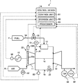
- FIG. 1 is a schematic diagram illustrating a gas turbine in accordance with an embodiment.
- FIG. 2 is block diagram illustrating the configuration of a processor.
- FIG. 3 is a flowchart illustrating an example of a method for evaluating characteristics of the gas turbine.
- FIG. 4 is a block diagram illustrating an example of an output model generating unit.
- FIG. 5 is a block diagram illustrating an example of an air intake flow amount model generating unit.
- FIG. 6 is a block diagram illustrating an example of a compressor efficiency model generating unit.
- FIG. 7 is a block diagram illustrating an example of a chamber pressure model generating unit.
- FIG. 8 is a graph illustrating an example of a correction value about an atmospheric temperature.
- FIG. 9 is a view schematically illustrating a state where a characteristic model is generated using a hierarchical neural network.
- FIG. 10 is a graph illustrating an example of a correction value about an atmospheric temperature.
- FIG. 11 is a flowchart illustrating procedures for updating a characteristic model.
- FIG. 12 is a graph illustrating an example of a correction value about an operation time.
- FIG. 13 is a block diagram illustrating an example of an output model generating unit.
- FIG. 14 is a graph illustrating relation between an operation time of the gas turbine and an elapsed time from a periodic inspection.
- FIG. 15 is a graph illustrating relation between an operation time and a correction coefficient when a periodic inspection are performed.
- FIG. 1 is a schematic diagram illustrating a gas turbine in accordance with the embodiment.
- a gas turbine 1 in accordance with the embodiment includes a compressor 11 , a combustor 12 , and a turbine 13 .
- a rotor 18 is arranged passing through the center part.
- the compressor 11 and the turbine 13 are connected to each other to be integrally rotatable by the rotor 18 .
- This gas turbine 1 is controlled by a control device 14 .
- a generator 15 is connected to the gas turbine 1 so that power can be generated.
- the gas turbine 1 also includes a cooling air supply line 19 that supplies cooling air from the compressor 11 to the turbine 13 .
- the cooling air supply line 19 is provided with a cooling air control valve 20 .
- the compressor 11 compresses air A that has been taken from an air inlet, and turns the air A into compressed air A 1 .
- an inlet guide vane (IGV: air intake valve) 22 adjusting an air intake amount of the air A that has been taken from the air inlet.
- IGV 22 an air intake amount of the air A is adjusted by adjusting an opening thereof.
- the IGV 22 includes a plurality of vane main bodies 22 a and an IGV operating unit 22 b for changing the vane angle of the vane main bodies 22 a .
- the vane angle of the vane main bodies 22 a is adjusted by the IGV operating unit 22 b , whereby the opening of the IGV 22 is adjusted and an air intake amount of the air A is adjusted.
- an air intake amount of the air A is increased and a pressure ratio of the compressor 11 is increased.
- an air intake amount of the air A is decreased and a pressure ratio of the compressor 11 is decreased.
- the combustor 12 supplies fuel F to the compressed air A 1 that has been compressed by the compressor 11 , and mixes and combusts the compressed air A 1 and the fuel F to generate combustion gas.
- the turbine 13 is rotated by the combustion gas that has been generated by the combustor 12 .
- the turbine 13 includes the rotor 18 , a plurality of stages of turbine vanes, and a plurality of stages of turbine blades. The stages of turbine vanes and the stages of turbine blades are alternately provided in an axial direction of the rotor 18 .
- the rotor 18 has both end parts in the axial direction rotatably supported by a bearing part, which is not illustrated, and is rotatably provided centering on an axis center.
- a drive axis of the generator 15 is connected to an end part of the rotor 18 on the compressor 11 side.
- the generator 15 is provided coaxially with the turbine 13 , and can generate power by rotation of the turbine 13 .
- the air A that has been taken from the air inlet of the compressor 11 becomes the compressed air A 1 of a high temperature and high pressure by passing through the inside of the compressor 11 via the IGV 22 and being compressed.
- the fuel F is supplied from the combustor 12 to this compressed air A 1 , and the compressed air A 1 and the fuel F are mixed and are combusted to generate combustion gas of a high temperature and high pressure.
- the combustion gas of a high temperature and high pressure that has been generated by the combustor 12 passes through the inside of the turbine 13 , and this combustion gas causes the turbine 13 to be operated (rotated) to drive the rotor 18 to be rotated.
- the rotation of the rotor 18 drives the generator 15 connected to the rotor 18 . In this manner, the generator 15 connected to the rotor 18 is driven to be rotated to generate power.
- the combustion gas driving the turbine 13 recovers heat as flue gas and is discharged to the atmosphere.
- the gas turbine 1 is provided with a chamber pressure indicator 51 , an air intake state detector 52 , a blade path thermometer 53 , a flue gas thermometer 54 , and a flowmeter 55 .
- the chamber pressure indicator 51 is provided to a line that circulates the compressed air A 1 from the compressor 11 to the combustor 12 .
- the chamber pressure indicator 51 is provided to the inside of a chamber of the combustor 12 , and measures pressure (chamber pressure) of the compressed air A 1 .
- the air intake state detector 52 detects an air intake temperature and air intake pressure of the air A taken into the compressor 11 .
- the blade path thermometer 53 is provided to a line that circulates flue gas discharged from the turbine 13 , and measures a temperature of flue gas that passes through a blade at a final stage provided to a downstream side of the turbine 13 in a flow direction of flue gas.
- the flue gas thermometer 54 is provided to a downstream side of the blade path thermometer 53 , and measures a temperature of flue gas.
- the flowmeter 55 measures a flow amount of cooling air flowing through the cooling air supply line 19 .
- the gas turbine 1 is provided with an output meter 56 for detecting output (load) of the gas turbine 1 .
- the control device 14 receives signals measured by the chamber pressure indicator 51 , the air intake state detector 52 , the blade path thermometer 53 , the flue gas thermometer 54 , the flowmeter 55 , and the output meter 56 .
- the control device 14 includes a control unit 61 , a storage unit 62 , and a processor (a characteristic evaluation device for a gas turbine) 63 .
- the control unit 61 controls the IGV 22 , a fuel adjusting valve 35 , and the like, based on the measurement result of the chamber pressure indicator 51 , the air intake state detector 52 , the blade path thermometer 53 , the flue gas thermometer 54 , the flowmeter 55 , and the like, and controls operation of the gas turbine 1 .
- the control unit 61 controls operation of the gas turbine 1 depending on output of the gas turbine 1 (output of the generator 15 ).
- control unit 61 can calculate operation data such as gas-turbine characteristics, inlet pressure loss, outlet pressure loss, the number of rotations, relative humidity, and an operation time, based on the measurement result of the chamber pressure indicator 51 , the air intake state detector 52 , the blade path thermometer 53 , the flue gas thermometer 54 , the flowmeter 55 , and the output meter 56 .
- the gas-turbine characteristics include characteristics of at least one of the compressor 11 , the combustor 12 , and the turbine 13 . Examples of the gas-turbine characteristics include output of the gas turbine 1 , an air intake flow amount of the compressor 11 , efficiency of the compressor 11 , and chamber pressure.
- the storage unit 62 stores therein various kinds of programs and data related to operation of the gas turbine 1 .
- FIG. 2 is block diagram illustrating the configuration of the processor 63 .
- the processor 63 includes a characteristic model generating unit 64 , a correction unit 65 , and an evaluation unit 66 .
- the characteristic model generating unit 64 calculates a model value of gas-turbine characteristics, based on operation data of the gas turbine 1 .
- the characteristic model generating unit 64 includes an output model generating unit 64 a , an air intake flow amount model generating unit 64 b , a compressor efficiency model generating unit 64 c , and a chamber pressure model generating unit 64 d .
- the output model generating unit 64 a generates a model of output characteristics of the gas turbine 1 .
- FIG. 4 is a block diagram illustrating an example of the output model generating unit 64 a .
- the output model generating unit 64 a receives an atmospheric temperature, atmospheric pressure, relative humidity, the number of rotations, inlet pressure loss, outlet pressure loss, and an operation time, as operation data.
- the output model generating unit 64 a generates an output model FX 1 that is a model of output characteristics of the gas turbine 1 , based on the respective operation data, and calculates a correction value of the respective operation data based on the generated output model FX 1 .
- the output model generating unit 64 a can use well-known techniques such as linear multi-regression analysis, non-linear multi-regression analysis, a neural network, and ensemble learning.
- FX 1 ⁇ a ( T ⁇ T 0) ⁇ b ( P ⁇ P 0) ⁇ c ( H ⁇ H 0) ⁇ d ( R ⁇ R 0) ⁇ e ( Pi ⁇ Pi 0) ⁇ f ( Pe ⁇ Pe 0) ⁇ g ( A ⁇ A 0)+ h
- a, b, c, d, e, f, g, and h are constants, and h indicates output (unit: MW) serving as a reference.
- the reference values of operation data T 0 , P 0 , H 0 , R 0 , Pi 0 , Pe 0 , and A 0 are values in environmental conditions serving as a reference of evaluation on output characteristics.
- the reference values can be preliminarily defined.
- the output model generating unit 64 a can obtain a correction value of the respective operation data using linear multi-regression analysis.
- FIG. 8 is a graph illustrating an example of a correction value about an atmospheric temperature.
- the longitudinal axis in FIG. 8 represents a correction coefficient (correction value), and the lateral axis represents an atmospheric temperature.
- a straight line 101 of an atmospheric temperature obtained by linear multi-regression analysis is linear so that a correction coefficient is smaller, for example, as the atmospheric temperature is higher. Characteristics such as an inclination of the straight line 101 are an example, and these are not limiting.
- FIG. 5 is a block diagram illustrating an example of the air intake flow amount model generating unit 64 b .
- the air intake flow amount model generating unit 64 b receives an atmospheric temperature, atmospheric pressure, and an operation time, as operation data.
- the air intake flow amount model generating unit 64 b generates an air intake flow amount model FX 2 that is a model of an air intake flow amount of the compressor 11 , based on the respective operation data.
- the air intake flow amount model generating unit 64 b generates an air intake flow amount model using well-known techniques such as linear multi-regression analysis, non-linear multi-regression analysis, a neural network, and ensemble learning, and can obtain, based on the generated air intake flow amount model, a correction value of the respective operation data using linear multi-regression analysis.
- FIG. 6 is a block diagram illustrating an example of the compressor efficiency model generating unit 64 c .
- the compressor efficiency model generating unit 64 c receives an atmospheric temperature, atmospheric pressure, and an operation time, as operation data.
- the compressor efficiency model generating unit 64 c generates a compressor efficiency model FX 3 that is a model of efficiency of the compressor 11 , based on the respective operation data.
- the compressor efficiency model generating unit 64 c generates a compressor efficiency model using well-known techniques such as linear multi-regression analysis, non-linear multi-regression analysis, a neural network, and ensemble learning, and can obtain, based on the generated compressor efficiency model, a correction value of the respective operation data using linear multi-regression analysis.
- FIG. 7 is a block diagram illustrating an example of the chamber pressure model generating unit 64 d .
- the chamber pressure model generating unit 64 d receives an atmospheric temperature, atmospheric pressure, and an operation time, as operation data.
- the chamber pressure model generating unit 64 d generates a chamber pressure model FX 4 that is a model of pressure characteristics (chamber pressure characteristics) of the compressed air A 1 , based on the respective operation data.
- the chamber pressure model generating unit 64 d generates a chamber pressure model using well-known techniques such as linear multi-regression analysis, non-linear multi-regression analysis, a neural network, and ensemble learning, and can obtain, based on the generated chamber pressure model, a correction value of the respective operation data using linear multi-regression analysis.
- the correction unit 65 illustrated in FIG. 2 obtains, about each of the gas-turbine characteristics, the gas-turbine characteristics after correction where the degree of influence caused by environmental conditions is eliminated or reduced from the gas-turbine characteristics.
- gas-turbine characteristics output of the gas turbine 1 will be described as an example.
- output of the gas turbine 1 when the correction values about an atmospheric temperature, about atmospheric pressure, about relative humidity, about the number of rotations, about inlet pressure loss, about outlet pressure loss, and about an operation time are defined as K1, K2, K3, K4, K5, K6, and K7, respectively, and a detection result of the output meter 56 is defined as G
- output G′ in environmental conditions serving as a reference can be obtained, for example, as follows.
- G′ G /( K 1 ⁇ K 2 ⁇ K 3 ⁇ K 4 ⁇ K 5 ⁇ K 6 ⁇ K 7)
- an air intake flow amount X′, compressor efficiency Z′, and chamber pressure Y′ in environmental conditions serving as a reference can be obtained similarly as follows.
- X′ X /( K 1 ⁇ K 2 ⁇ K 7)
- Y′ Y /( K 1 ⁇ K 2 ⁇ K 7)
- Z′ Z /( K 1 ⁇ K 2 ⁇ K 7)
- the evaluation unit 66 evaluates the obtained gas-turbine characteristics after correction.
- the output G′ that has been corrected by the correction unit 65 is a value where influence due to environmental conditions has been eliminated or reduced.
- the evaluation unit 66 can evaluate, for example, based on the output G′ that has been obtained by the correction unit 65 , a change and the like in output of the gas turbine 1 due to contamination, deterioration, and the like. In this case, an evaluation can be made by preliminarily obtaining a reference value of output of the gas turbine 1 in the reference environmental conditions and comparing with the reference value.
- output of the gas turbine 1 in, for example, a state where there are no contamination, deterioration, and the like in the reference environmental conditions or a state where contamination, deterioration, and the like are less than a predetermined threshold can be defined.
- the evaluation unit 66 may evaluate a factor of a change in output, based on the difference between the reference value and a measurement value of output of the gas turbine 1 .
- the evaluation unit 66 can similarly evaluate, based on each of the gas-turbine characteristics that have been corrected by the correction unit 65 , a change in gas-turbine characteristics due to contamination, deterioration, and the like, a factor of a change in gas-turbine characteristics, and the like.
- each of the characteristic models is generated using linear multi-regression analysis.
- the output model generating unit 64 a , the air intake flow amount model generating unit 64 b , the compressor efficiency model generating unit 64 c , and the chamber pressure model generating unit 64 d each receive operation data such as an atmospheric temperature, characteristics (output, an air intake flow amount, compressor efficiency, and chamber pressure) as a theoretical value are calculated. These characteristics are values corresponding to gas-turbine characteristics that have been corrected based on the correction values.
- the evaluation unit 66 may make an evaluation by comparing the measurement value of output, an air intake flow amount, compressor efficiency, and chamber pressure with a theoretical value calculated by linear multi-regression analysis.
- Each unit in the characteristic model generating unit 64 receives a value of an operation time, as operation data, to calculate a degree of a change in gas-turbine characteristics due to lapse of an operation time, in other words, a degree of a change in gas-turbine characteristics due to deterioration.
- the evaluation unit 66 may make an evaluation on deterioration, by comparing corrected gas-turbine characteristics with a degree of a change in gas-turbine characteristics due to calculated deterioration.
- FIG. 3 is a flowchart illustrating an example of a method for evaluating characteristics of the gas turbine.
- the processor 63 calculates a correction value for correcting influence on gas-turbine characteristics due to environmental conditions (step S 10 ).
- the characteristic model generating unit 64 generates a characteristic model about each characteristic of the gas turbine 1 , and calculates a correction value of operation data based on the generated characteristic model.
- the processor 63 corrects gas-turbine characteristics, based on the calculated correction value (step S 20 ).
- the correction unit 65 obtains gas-turbine characteristics after correction in the environmental conditions serving as a reference, based on the correction value that has been calculated for each gas-turbine characteristic.
- the gas-turbine characteristics after correction are the value where influence due to environmental conditions is eliminated or reduced.
- the processor 63 makes an evaluation based on the gas-turbine characteristics after correction (step S 30 ).
- the evaluation unit 66 makes an evaluation on gas-turbine characteristics, by comparing the gas-turbine characteristics after correction with an actual measurement value of gas-turbine characteristics. A highly accurate evaluation can be obtained because the evaluation is based on the gas-turbine characteristics where influence due to environmental conditions is eliminated or reduced.
- the characteristic evaluation device for a gas turbine according to the present embodiment calculates a correction value for correcting influence due to environmental conditions based on operation data of the gas turbine 1 , and therefore can obtain a highly accurate correction value.
- the device for evaluating characteristics of a gas turbine according to the present embodiment can make a highly accurate evaluation.
- the characteristic evaluation device for a gas turbine according to the present embodiment can calculate a degree of a change in gas-turbine characteristics due to deterioration.
- the device for evaluating characteristics of a gas turbine according to the present embodiment can evaluate deterioration characteristics depending on environmental conditions in which each gas turbine 1 is placed and respective operation data for each gas turbine 1 to make a highly accurate evaluation.
- a technical scope of the present invention is not limited to the embodiment, and various changes may be made as appropriate without departing from the significance of the present invention.
- a case where the characteristic model generating unit 64 generates a characteristic model using linear multi-regression analysis has been described as an example, but this is not limiting.
- a characteristic model may be generated using a non-linear method.
- the characteristic model generating unit 64 can generate a characteristic model, for example, using a neural network as the non-linear method.
- FIG. 9 is a view schematically illustrating a state where a characteristic model is generated using a hierarchical neural network.
- FIG. 9 illustrates an output model generating unit 64 e that outputs the output model FX 1 as an example of the characteristic model generating unit.
- the output model generating unit 64 e includes a first layer L 1 serving as a reception layer, second, third, and fourth layers L 2 , L 3 and L 4 , serving as intermediate layers, and a fifth layer L 5 serving as an output layer.
- the intermediate layer is made of three layers, but this is not limiting.
- the intermediate layer may be made of two layers or less, or four layers or more.
- the first layer L 1 , the second layer L 2 , the third layer L 3 , the fourth layer L 4 , and the fifth layer L 5 each include one or a plurality of nodes n.
- the first layer L 1 includes seven nodes n (n 1 , n 2 , n 3 , n 4 , n 5 , n 6 , and n 7 ).
- the node n 1 receives an atmospheric temperature.
- the node n 2 receives atmospheric pressure.
- the node n 3 receives relative humidity.
- the node n 4 receives the number of rotations.
- the node n 5 receives inlet pressure loss.
- the node n 6 receives outlet pressure loss.
- the node n 7 receives an operation time.
- the seven nodes n of the first layer L 1 each output a signal to each node n in the second layer L 2 .
- the second layer L 2 includes, for example, six nodes n.
- the six nodes n in the second layer L 2 each receive a signal that has been output from the seven nodes n in the first layer L 1 .
- the six nodes n in the second layer L 2 each output a signal to each node n in the third layer L 3 .
- the number of nodes n is not limited to six, and may be equal to or less than five or equal to or more than seven.
- the second layer L 3 includes three nodes n.
- the three nodes n in the third layer L 3 each receive a signal that has been output from the six nodes n in the second layer L 2 .
- the six nodes n in the third layer L 3 each output a signal to each node n in the fourth layer L 4 .
- the number of nodes n is not limited to three, and may be equal to or less than two or equal to or more than four.
- the fourth layer L 4 includes six nodes n.
- the six nodes n in the fourth layer L 4 each receive a signal that has been output from the three nodes n in the third layer L 3 .
- the six nodes n in the fourth layer L 4 each output a signal to a node n in the fifth layer L 5 .
- the number of nodes n is not limited to six, and may be equal to or less than five or equal to or more than seven.
- the fifth layer L 5 includes one node n.
- the three nodes n in the fifth layer L 5 receive a signal that has been output from the six nodes n in the fourth layer L 4 .
- the node n in the fifth layer L 5 outputs, for example, the output model FX 1 .
- the number of nodes n is not limited to one, and may be equal to or more than two.
- the output model generating unit 64 e outputs the output model FX 1 using a neural network
- the chamber pressure model generating unit that outputs the chamber pressure model FX 4 may output each characteristic model using a neural network described above.
- the number of nodes of the reception layer, the number of layers in the respective intermediate layers, and the number of nodes in each layer can be changed as appropriate depending on the kinds of input signals.
- FIG. 9 the case where a hierarchical neural network is used has been described as an example, but this is not limiting.
- a neural network different from the hierarchical neural network, for example, an interconnecting neural network may be used.
- FIG. 10 is a graph illustrating an example of a correction value about an atmospheric temperature.
- the longitudinal axis in FIG. 10 represents a correction coefficient (correction value), and the lateral axis represents an atmospheric temperature.
- a curve line 102 of an atmospheric temperature is curved.
- a non-linear method such as the neural network illustrated in FIG. 9 .
- a more highly accurate correction value can be obtained. For example, even when it is difficult to preliminarily understand characteristics such as a change in output of the gas turbine 1 with respect to an operation time, a more highly accurate correction value can be obtained.
- the characteristic model generating unit 64 may sequentially update a characteristic model of gas-turbine characteristics.
- FIG. 11 is a flowchart illustrating procedures for updating a characteristic model.
- the characteristic model generating unit 64 detects the presence or absence of a flag for updating a characteristic model (step S 40 ).
- a flag for updating a characteristic model can be generated, for example, when a predetermined period elapses (for example, when one day elapses, when one week elapses, and when one month elapses) and when a predetermined periodic inspection is performed.
- the characteristic model generating unit 64 repeats the processing at step S 40 .
- the characteristic model generating unit 64 updates a characteristic model of gas-turbine characteristics (step S 50 ).
- the characteristic model generating unit 64 newly generates a characteristic model based on the received operation data. Because the generated characteristic model is newly generated in a state where operation data has been accumulated after the previous characteristic model was generated, the generated characteristic model becomes a more highly accurate characteristic model.
- the characteristic model generating unit 64 calculates a correction value for each operation data, based on the generated characteristic model.
- the correction unit 65 corrects gas-turbine characteristics, based on the newly calculated correction value.
- the evaluation unit 66 makes an evaluation based on the gas-turbine characteristics that have been corrected based on the new correction value. Thus, a highly accurate evaluation is obtained.
- the characteristic model generating unit 64 repeats operation from step S 40 .
- the characteristic model generating unit 64 ends the processing.
- the characteristic model generating unit 64 can calculate a correction value, based on the accumulated operation data by updating a characteristic model.
- a highly accurate evaluation can be obtained.
- the characteristic model generating unit 64 may predict (i.e., estimate) and calculate a future correction value based on the obtained correction value.
- FIG. 12 is a graph illustrating an example of a correction value about an operation time.
- the longitudinal axis in FIG. 12 represents a correction coefficient (correction value), and the lateral axis represents an operation time.
- a correction value up to the time t 1 is calculated as a correction value of an operation time.
- a straight line 103 is a correction value obtained by, for example, linear multi-regression analysis.
- a curve line 104 is a correction value obtained by, for example, a non-linear method. In each case, a correction value up to the time t 1 is calculated.
- the characteristic model generating unit 64 may predict a future correction value, for example, a correction value up to a time t 2 later than the time t 1 , based on the inclination of the straight line 103 and the curve line 104 .
- the straight line 103 a and the curve line 104 a indicate correction values that have been predicted based on the straight line 103 and the curve line 104 , respectively.
- the correction unit 65 may calculate, by correcting gas-turbine characteristics based on the predicted correction value, the gas-turbine characteristics after future correction.
- the evaluation unit 66 may make an evaluation based on the gas-turbine characteristics that have been calculated after future correction. In this manner, an evaluation related to future gas-turbine characteristics can be obtained.
- the output model generating unit 64 a receives an atmospheric temperature, atmospheric pressure, relative humidity, the number of rotations, inlet pressure loss, outlet pressure loss, and an operation time, as operation data, has been described as an example, but this is not limiting.
- the output model generating unit 64 a may receive other operation data.
- FIG. 13 is a block diagram illustrating an example of the output model generating unit 64 a .
- the output model generating unit 64 a may receive data of an elapsed time from a periodic inspection, in addition to the above-mentioned operation data.
- the output model generating unit 64 a generates an output model FX 1 a that is a model of output characteristics of the gas turbine 1 , based on the respective operation data, and calculates a correction value of the respective operation data based on the generated output model FX 1 a.
- FIG. 14 is a graph illustrating relation between an operation time of the gas turbine 1 and an elapsed time from a periodic inspection.
- the periodic inspection of the gas turbine 1 are periodically performed, for example, at a time t 3 , a time t 4 , a time t 5 , and a time t 6 from the start of operation.
- a broken line 105 indicates a state where an elapsed time is reset for each periodic inspection.
- the periodic inspection include, for example, a combustor inspection that is an inspection of the combustor 12 , a turbine inspection that is an inspection of the turbine 13 , and a major inspection. By performing the turbine inspection, the combustor inspection is also performed. By performing the major inspection, the turbine inspection and the combustor inspection are also performed.
- FIG. 15 is a graph illustrating relation between an operation time and a correction coefficient when periodical inspection are performed.
- a periodic inspection whenever a periodic inspection is performed, a decrease in output is improved, for example. In other words, whenever a periodic inspection is performed, output is increased.
- the output model generating unit 64 a calculates a correction value at each of the times t 3 , t 4 , t 5 , and t 6 at when a periodic inspection are performed from the start of operation so that influence of an output increase is eliminated or reduced.
- a shape of a broken line 106 indicating a correction value represents a state where the correction value is rapidly increased at times t 3 , t 4 , t 5 , and t 6 , for example.
- a more highly accurate correction value and thus evaluation can be obtained by reflecting the influence of periodic inspection on gas-turbine characteristics such as output.
Landscapes
- Engineering & Computer Science (AREA)
- Chemical & Material Sciences (AREA)
- Combustion & Propulsion (AREA)
- Mechanical Engineering (AREA)
- General Engineering & Computer Science (AREA)
- Physics & Mathematics (AREA)
- General Physics & Mathematics (AREA)
- Testing Of Devices, Machine Parts, Or Other Structures Thereof (AREA)
- Testing Of Engines (AREA)
Abstract
Description
FX1=−a(T−T0)−b(P−P0)−c(H−H0)−d(R−R0)−e(Pi−Pi0)−f(Pe−Pe0)−g(A−A0)+h
G′=G/(K1·K2·K3·K4·K5·K6·K7)
X′=X/(K1·K2·K7)
Y′=Y/(K1·K2·K7)
Z′=Z/(K1·K2·K7)
-
- 1 Gas turbine
- 11 Compressor
- 12 Combustor
- 13 Turbine
- 14 Control device
- 15 Generator
- 18 Rotor
- 19 Cooling air supply line
- 20 Cooling air control valve
- 22 Inlet guide vane
- 22 a Vane main body
- 22 b IGV operating unit
- 35 Fuel adjusting valve
- 51 Chamber pressure indicator
- 52 Air intake state detector
- 53 Blade path thermometer
- 54 Flue gas thermometer
- 55 Flowmeter
- 56 Output meter
- 61 Control unit
- 62 Storage unit
- 63 Processor
- 64 Characteristic model generating unit
- 64 a, 64 e Output model generating unit
- 64 b Air intake flow amount model generating unit
- 64 c Compressor efficiency model generating unit
- 64 d Chamber pressure model generating unit
- 65 Correction unit
- 66 Evaluation unit
- 101, 103, 103 a Straight line
- 102, 104, 104 a Curve line
- 105, 106 Broken line
- A Air
- A1 Compressed air
- F Fuel
- H0, P0, R0, T0, Pe0, Pi0 Reference value
- FX1, FX1 a Output model
- FX2 Air intake flow amount model
- FX3 Compressor efficiency model
- FX4 Chamber pressure model
- L1 First layer
- L2 Second layer
- L3 Third layer
- L4 Fourth layer
- L5 Fifth layer
- n, n1, n2, n3, n4, n5, n6, n7 Node
- t1, t2, t3, t4, t5, t6 Time
Claims (4)
Applications Claiming Priority (3)
| Application Number | Priority Date | Filing Date | Title |
|---|---|---|---|
| JP2016057187A JP6786233B2 (en) | 2016-03-22 | 2016-03-22 | Gas turbine characterization device and gas turbine characterization method |
| JP2016-057187 | 2016-03-22 | ||
| PCT/JP2016/085176 WO2017163489A1 (en) | 2016-03-22 | 2016-11-28 | Gas turbine characteristic evaluation device and gas turbine characteristic evaluation method |
Publications (2)
| Publication Number | Publication Date |
|---|---|
| US20190080523A1 US20190080523A1 (en) | 2019-03-14 |
| US10636224B2 true US10636224B2 (en) | 2020-04-28 |
Family
ID=59901089
Family Applications (1)
| Application Number | Title | Priority Date | Filing Date |
|---|---|---|---|
| US16/083,282 Active US10636224B2 (en) | 2016-03-22 | 2016-11-28 | Characteristic evaluation device for gas turbine and characteristic evaluation method for gas turbine |
Country Status (8)
| Country | Link |
|---|---|
| US (1) | US10636224B2 (en) |
| JP (1) | JP6786233B2 (en) |
| KR (1) | KR20180110678A (en) |
| CN (1) | CN108779713B (en) |
| DE (1) | DE112016006642B4 (en) |
| MX (1) | MX2018011093A (en) |
| PH (1) | PH12018502009A1 (en) |
| WO (1) | WO2017163489A1 (en) |
Families Citing this family (4)
| Publication number | Priority date | Publication date | Assignee | Title |
|---|---|---|---|---|
| CA3135985A1 (en) | 2019-05-13 | 2020-11-19 | Rudy Charles Andre AULNETTE | Model resetting in a turbine engine |
| FR3096137B1 (en) * | 2019-05-13 | 2021-04-23 | Safran Aircraft Engines | PS3 model registration in a turbomachine |
| KR102452608B1 (en) * | 2021-03-04 | 2022-10-07 | 인하대학교 산학협력단 | Method for Gas turbine control based on artificial intelligence and apparatus thereof |
| JP7458357B2 (en) | 2021-09-24 | 2024-03-29 | 三菱パワー株式会社 | Model learning device, performance evaluation device, model learning method, and program |
Citations (42)
| Publication number | Priority date | Publication date | Assignee | Title |
|---|---|---|---|---|
| JP2002073156A (en) | 2000-09-04 | 2002-03-12 | Kawasaki Heavy Ind Ltd | Method and device for diagnosing gas turbine operating state |
| JP2003083089A (en) | 2001-09-14 | 2003-03-19 | Ishikawajima Harima Heavy Ind Co Ltd | Performance diagnosis method for gas turbine |
| US20070012044A1 (en) | 2005-07-18 | 2007-01-18 | Osborn Brock E | System and method for trending exhaust gas temperature in a turbine engine |
| JP2007192138A (en) | 2006-01-19 | 2007-08-02 | Mitsubishi Heavy Ind Ltd | Method and device for monitoring anomaly in gas turbine |
| US20110106680A1 (en) | 2009-10-30 | 2011-05-05 | General Electric Company | Turbine operation degradation determination system and method |
| US20130054031A1 (en) * | 2011-08-24 | 2013-02-28 | Kevin Wood Wilkes | Methods and systems for gas turbine modeling using adaptive kalman filter |
| US20130066615A1 (en) * | 2011-09-14 | 2013-03-14 | General Electric Company | System and method for simulating gas turbine operation |
| US20130073170A1 (en) * | 2011-09-15 | 2013-03-21 | General Electric Company | System and method for simulating a gas turbine compressor |
| US20140093350A1 (en) * | 2012-09-28 | 2014-04-03 | United Technologies Corporation | Real time model based compressor control |
| US20140156165A1 (en) * | 2012-11-30 | 2014-06-05 | General Electric Company | System and method for gas turbine operation |
| US20140227109A1 (en) * | 2013-02-08 | 2014-08-14 | GM Global Technology Operations LLC | Turbocharger flow control |
| US20140257666A1 (en) * | 2013-03-08 | 2014-09-11 | General Electric Company | Online Enhancement for Improved Gas Turbine Performance |
| US20150027100A1 (en) * | 2013-07-23 | 2015-01-29 | Rolls-Royce Controls And Data Services Limited | System for performing staging control of a multi-stage combustor |
| US20150066223A1 (en) * | 2013-09-04 | 2015-03-05 | General Electric Company | Automatic Switching of HMI Screens Based on Process, Task, and Abnormal Deviation in a Power Plant |
| US20150068191A1 (en) * | 2013-09-10 | 2015-03-12 | MAGNETI MARELLI S.p.A. | Method for the correction of the reduced mass flow rate of a compressor in an internal combustion engine turbocharged by means of a turbocharger |
| US20150081121A1 (en) * | 2013-09-17 | 2015-03-19 | General Electric Company | System and method for controlling operation of a gas turbine based power plant |
| US20150168229A1 (en) * | 2013-12-18 | 2015-06-18 | Upul P. Desilva | Active temperature monitoring in gas turbine combustors |
| US20150171705A1 (en) * | 2012-08-03 | 2015-06-18 | Hitachi, Ltd. | Dual-shaft gas turbine power generation system, and control device and control method for gas turbine system |
| US20150185716A1 (en) * | 2013-12-31 | 2015-07-02 | General Electric Company | Methods and systems for enhancing control of power plant generating units |
| US20150226133A1 (en) * | 2012-12-31 | 2015-08-13 | Exxonmobil Upstream Research Company | Gas turbine load control system |
| US20150244007A1 (en) * | 2012-11-22 | 2015-08-27 | Mitsubishi Hitachi Power Systems, Ltd. | Power generation system and method of operating power generation system |
| US20150315978A1 (en) * | 2012-12-03 | 2015-11-05 | Siemens Aktiengesellschaft | Method and arrangement for controlling fuel supply for a gas turbine |
| US20150315979A1 (en) * | 2012-12-03 | 2015-11-05 | Siemens Aktiengesellschaft | Gas turbine fuel supply method and arrangement |
| US20150354466A1 (en) * | 2013-02-26 | 2015-12-10 | Mitsubishi Hitachi Power Systems, Ltd. | Gas turbine system, controller, and gas turbine operation method |
| US20150377146A1 (en) * | 2014-06-30 | 2015-12-31 | General Electric Company | Erosion suppression system and method in an exhaust gas recirculation gas turbine system |
| US20160003164A1 (en) * | 2013-03-15 | 2016-01-07 | United Technologies Corporation | Compact aero-thermo model stabilization with compressible flow function transform |
| US20160010495A1 (en) * | 2014-07-11 | 2016-01-14 | Alstom Technology Ltd. | Method for the control and protection of a gas turbine and gas turbine using such method |
| US20160010493A1 (en) * | 2014-01-21 | 2016-01-14 | General Electric Company | System and method of control for a gas turbine engine |
| US20160025596A1 (en) * | 2014-07-24 | 2016-01-28 | General Electric Company | Method and systems for detection compressor surge |
| US20160146118A1 (en) * | 2013-12-31 | 2016-05-26 | General Electric Company | Methods and systems for enhancing control of power plant generating units |
| US20160147204A1 (en) * | 2014-11-26 | 2016-05-26 | General Electric Company | Methods and systems for enhancing control of power plant generating units |
| US20160222816A1 (en) * | 2015-02-03 | 2016-08-04 | General Electric Company | Correction system and method for gas turbine proportional droop governor |
| US20160252015A1 (en) * | 2013-11-27 | 2016-09-01 | Hitachi, Ltd. | Gas Turbine Corresponding to Renewable Energy and Control Method Therefor |
| US20160273457A1 (en) * | 2013-10-30 | 2016-09-22 | Siemens Aktiengesellschaft | Partial-load operation of a gas turbine with an adjustable bypass flow channel |
| US20160281607A1 (en) * | 2015-03-27 | 2016-09-29 | General Electric Company | Methods and systems for enhancing operation of power plant generating units and systems |
| US20170030259A1 (en) * | 2015-07-31 | 2017-02-02 | Toyota Jidosha Kabushiki Kaisha | Control apparatus for internal combustion engine |
| US20170074175A1 (en) * | 2014-03-25 | 2017-03-16 | Mitsubishi Hitachi Power Systems, Ltd. | Gas turbine combustion control device and combustion control method and program therefor |
| US20170101946A1 (en) * | 2015-10-10 | 2017-04-13 | GM Global Technology Operations LLC | Method of controlling the operation of an air charging system of an internal combustion engine |
| US20170138272A1 (en) * | 2014-06-18 | 2017-05-18 | Hitachi, Ltd. | Multi-Shaft Variable Speed Gas Turbine Apparatus and Method of Controlling the Same |
| US20170175567A1 (en) * | 2015-12-18 | 2017-06-22 | General Electric Company | Model-based performance estimation |
| US20180306124A1 (en) * | 2017-04-24 | 2018-10-25 | Doosan Heavy Industries & Construction Co., Ltd. | Gas turbine system and control apparatus and method thereof |
| US20190063335A1 (en) * | 2016-03-09 | 2019-02-28 | Mitsubishi Hitachi Power Systems, Ltd. | Control device for gas turbine and control method for gas turbine |
Family Cites Families (5)
| Publication number | Priority date | Publication date | Assignee | Title |
|---|---|---|---|---|
| JPH05195720A (en) * | 1992-01-21 | 1993-08-03 | Toshiba Corp | Managing method for degradation in performance of plant |
| US6823675B2 (en) * | 2002-11-13 | 2004-11-30 | General Electric Company | Adaptive model-based control systems and methods for controlling a gas turbine |
| US8171717B2 (en) * | 2010-05-14 | 2012-05-08 | General Electric Company | Model-based coordinated air-fuel control for a gas turbine |
| US9322333B2 (en) * | 2012-01-06 | 2016-04-26 | General Electric Company | System and method for determining a cooling flow parameter downstream from a gas turbine combustor |
| CN102953835B (en) * | 2012-11-09 | 2014-11-19 | 沈阳黎明航空发动机(集团)有限责任公司 | Control device and control method for stable running of gas turbine |
-
2016
- 2016-03-22 JP JP2016057187A patent/JP6786233B2/en active Active
- 2016-11-28 WO PCT/JP2016/085176 patent/WO2017163489A1/en active Application Filing
- 2016-11-28 MX MX2018011093A patent/MX2018011093A/en unknown
- 2016-11-28 DE DE112016006642.2T patent/DE112016006642B4/en active Active
- 2016-11-28 KR KR1020187026829A patent/KR20180110678A/en not_active Application Discontinuation
- 2016-11-28 US US16/083,282 patent/US10636224B2/en active Active
- 2016-11-28 CN CN201680083800.1A patent/CN108779713B/en active Active
-
2018
- 2018-09-19 PH PH12018502009A patent/PH12018502009A1/en unknown
Patent Citations (44)
| Publication number | Priority date | Publication date | Assignee | Title |
|---|---|---|---|---|
| JP2002073156A (en) | 2000-09-04 | 2002-03-12 | Kawasaki Heavy Ind Ltd | Method and device for diagnosing gas turbine operating state |
| JP2003083089A (en) | 2001-09-14 | 2003-03-19 | Ishikawajima Harima Heavy Ind Co Ltd | Performance diagnosis method for gas turbine |
| US20070012044A1 (en) | 2005-07-18 | 2007-01-18 | Osborn Brock E | System and method for trending exhaust gas temperature in a turbine engine |
| JP2007192138A (en) | 2006-01-19 | 2007-08-02 | Mitsubishi Heavy Ind Ltd | Method and device for monitoring anomaly in gas turbine |
| US20110106680A1 (en) | 2009-10-30 | 2011-05-05 | General Electric Company | Turbine operation degradation determination system and method |
| JP2011094620A (en) | 2009-10-30 | 2011-05-12 | General Electric Co <Ge> | System and method for determining operating deterioration of turbine |
| US20130054031A1 (en) * | 2011-08-24 | 2013-02-28 | Kevin Wood Wilkes | Methods and systems for gas turbine modeling using adaptive kalman filter |
| US20130066615A1 (en) * | 2011-09-14 | 2013-03-14 | General Electric Company | System and method for simulating gas turbine operation |
| US20130073170A1 (en) * | 2011-09-15 | 2013-03-21 | General Electric Company | System and method for simulating a gas turbine compressor |
| US20150171705A1 (en) * | 2012-08-03 | 2015-06-18 | Hitachi, Ltd. | Dual-shaft gas turbine power generation system, and control device and control method for gas turbine system |
| US20140093350A1 (en) * | 2012-09-28 | 2014-04-03 | United Technologies Corporation | Real time model based compressor control |
| US20150244007A1 (en) * | 2012-11-22 | 2015-08-27 | Mitsubishi Hitachi Power Systems, Ltd. | Power generation system and method of operating power generation system |
| JP2014111937A (en) | 2012-11-30 | 2014-06-19 | General Electric Co <Ge> | System and method for gas turbine operation |
| US20140156165A1 (en) * | 2012-11-30 | 2014-06-05 | General Electric Company | System and method for gas turbine operation |
| US20150315979A1 (en) * | 2012-12-03 | 2015-11-05 | Siemens Aktiengesellschaft | Gas turbine fuel supply method and arrangement |
| US20150315978A1 (en) * | 2012-12-03 | 2015-11-05 | Siemens Aktiengesellschaft | Method and arrangement for controlling fuel supply for a gas turbine |
| US20150226133A1 (en) * | 2012-12-31 | 2015-08-13 | Exxonmobil Upstream Research Company | Gas turbine load control system |
| US20140227109A1 (en) * | 2013-02-08 | 2014-08-14 | GM Global Technology Operations LLC | Turbocharger flow control |
| US20150354466A1 (en) * | 2013-02-26 | 2015-12-10 | Mitsubishi Hitachi Power Systems, Ltd. | Gas turbine system, controller, and gas turbine operation method |
| US20140257666A1 (en) * | 2013-03-08 | 2014-09-11 | General Electric Company | Online Enhancement for Improved Gas Turbine Performance |
| US20160003164A1 (en) * | 2013-03-15 | 2016-01-07 | United Technologies Corporation | Compact aero-thermo model stabilization with compressible flow function transform |
| US20150027100A1 (en) * | 2013-07-23 | 2015-01-29 | Rolls-Royce Controls And Data Services Limited | System for performing staging control of a multi-stage combustor |
| US20150066223A1 (en) * | 2013-09-04 | 2015-03-05 | General Electric Company | Automatic Switching of HMI Screens Based on Process, Task, and Abnormal Deviation in a Power Plant |
| US20150068191A1 (en) * | 2013-09-10 | 2015-03-12 | MAGNETI MARELLI S.p.A. | Method for the correction of the reduced mass flow rate of a compressor in an internal combustion engine turbocharged by means of a turbocharger |
| US20150081121A1 (en) * | 2013-09-17 | 2015-03-19 | General Electric Company | System and method for controlling operation of a gas turbine based power plant |
| US20160273457A1 (en) * | 2013-10-30 | 2016-09-22 | Siemens Aktiengesellschaft | Partial-load operation of a gas turbine with an adjustable bypass flow channel |
| US20160252015A1 (en) * | 2013-11-27 | 2016-09-01 | Hitachi, Ltd. | Gas Turbine Corresponding to Renewable Energy and Control Method Therefor |
| US20150168229A1 (en) * | 2013-12-18 | 2015-06-18 | Upul P. Desilva | Active temperature monitoring in gas turbine combustors |
| US20160146118A1 (en) * | 2013-12-31 | 2016-05-26 | General Electric Company | Methods and systems for enhancing control of power plant generating units |
| US20150185716A1 (en) * | 2013-12-31 | 2015-07-02 | General Electric Company | Methods and systems for enhancing control of power plant generating units |
| US20160010493A1 (en) * | 2014-01-21 | 2016-01-14 | General Electric Company | System and method of control for a gas turbine engine |
| US20170074175A1 (en) * | 2014-03-25 | 2017-03-16 | Mitsubishi Hitachi Power Systems, Ltd. | Gas turbine combustion control device and combustion control method and program therefor |
| US20170138272A1 (en) * | 2014-06-18 | 2017-05-18 | Hitachi, Ltd. | Multi-Shaft Variable Speed Gas Turbine Apparatus and Method of Controlling the Same |
| US20150377146A1 (en) * | 2014-06-30 | 2015-12-31 | General Electric Company | Erosion suppression system and method in an exhaust gas recirculation gas turbine system |
| US20160010495A1 (en) * | 2014-07-11 | 2016-01-14 | Alstom Technology Ltd. | Method for the control and protection of a gas turbine and gas turbine using such method |
| US20160025596A1 (en) * | 2014-07-24 | 2016-01-28 | General Electric Company | Method and systems for detection compressor surge |
| US20160147204A1 (en) * | 2014-11-26 | 2016-05-26 | General Electric Company | Methods and systems for enhancing control of power plant generating units |
| US20160222816A1 (en) * | 2015-02-03 | 2016-08-04 | General Electric Company | Correction system and method for gas turbine proportional droop governor |
| US20160281607A1 (en) * | 2015-03-27 | 2016-09-29 | General Electric Company | Methods and systems for enhancing operation of power plant generating units and systems |
| US20170030259A1 (en) * | 2015-07-31 | 2017-02-02 | Toyota Jidosha Kabushiki Kaisha | Control apparatus for internal combustion engine |
| US20170101946A1 (en) * | 2015-10-10 | 2017-04-13 | GM Global Technology Operations LLC | Method of controlling the operation of an air charging system of an internal combustion engine |
| US20170175567A1 (en) * | 2015-12-18 | 2017-06-22 | General Electric Company | Model-based performance estimation |
| US20190063335A1 (en) * | 2016-03-09 | 2019-02-28 | Mitsubishi Hitachi Power Systems, Ltd. | Control device for gas turbine and control method for gas turbine |
| US20180306124A1 (en) * | 2017-04-24 | 2018-10-25 | Doosan Heavy Industries & Construction Co., Ltd. | Gas turbine system and control apparatus and method thereof |
Non-Patent Citations (3)
| Title |
|---|
| International Search Report dated Feb. 14, 2017 in International (PCT) Application No. PCT/JP2016/085176. |
| Notice of Reasons for Refusal dated Jan. 28, 2020 in Japanese Application No. 2016-057187, with English translation. |
| Written Opinion of the International Searching Authority dated Feb. 14, 2017 in International (PCT) Application No. PCT/JP2016/085176. |
Also Published As
| Publication number | Publication date |
|---|---|
| US20190080523A1 (en) | 2019-03-14 |
| PH12018502009A1 (en) | 2019-07-01 |
| WO2017163489A1 (en) | 2017-09-28 |
| CN108779713B (en) | 2020-11-13 |
| JP6786233B2 (en) | 2020-11-18 |
| CN108779713A (en) | 2018-11-09 |
| JP2017172391A (en) | 2017-09-28 |
| KR20180110678A (en) | 2018-10-10 |
| MX2018011093A (en) | 2018-11-22 |
| DE112016006642T5 (en) | 2018-12-20 |
| DE112016006642B4 (en) | 2023-07-06 |
Similar Documents
| Publication | Publication Date | Title |
|---|---|---|
| US10636224B2 (en) | Characteristic evaluation device for gas turbine and characteristic evaluation method for gas turbine | |
| CN105980945B (en) | The estimation of component health parameters in industrial gas turbines | |
| US20100023238A1 (en) | Method and systems for controlling gas turbine engine temperature | |
| RU2406990C1 (en) | Procedure for operating gas turbine installation | |
| US9856795B2 (en) | Gas turbine system, controller, and gas turbine operation method | |
| JP2003129866A (en) | Adaptive aero-thermodynamic engine model | |
| JP6636021B2 (en) | How to identify emission behavior | |
| US11536197B2 (en) | Valve opening degree determination device for cooling-air adjustment valve, disk cavity target temperature determination device, and disk cavity temperature control device | |
| US20180307997A1 (en) | Systems and methods for improved quantification of uncertainty in turbomachinery | |
| JP6889008B2 (en) | Controlling the machine with a calibrated performance model | |
| US10466661B2 (en) | Model-based performance estimation | |
| JP6906935B2 (en) | Equipment-specific stochastic controls, related control systems, computer program products, and methods for gas turbine regulation with respect to output-emission parameters. | |
| CN106050435B (en) | Regulation and control system, computer program product and method for a gas turbine | |
| JP6640534B2 (en) | Control system, computer program product, and method associated with application of fuel flow based stochastic control in gas turbine tuning under partial load | |
| CN105604703B (en) | For tuning computing device, the system and method for combustion gas turbine | |
| US20210040899A1 (en) | Analysis method for a gas turbine | |
| US11525412B2 (en) | Operation management device, power generation plant, and operation management method for power generation plant | |
| JP2012002126A (en) | Exhaust gas temperature estimating device, exhaust gas temperature estimating method, and gas turbine plant | |
| Hipple et al. | Using machine learning to increase model performance for a gas turbine system | |
| Rudolf et al. | Modelling of gas turbine nox emissions based on long-term operation data | |
| Kim et al. | Suitability of performance adaptation methods for updating the thermodynamic cycle model of a turboprop engine | |
| Herrera et al. | A comparative analysis of turbine rotor inlet temperature models | |
| KR20220144627A (en) | Method for optimizing cleaning cycle by analyzing the performance change due to contamination of the gas turbine compressor based on the physical model | |
| JP2010248966A (en) | Method for controlling gas turbine combustor |
Legal Events
| Date | Code | Title | Description |
|---|---|---|---|
| AS | Assignment |
Owner name: MITSUBISHI HITACHI POWER SYSTEMS, LTD., JAPAN Free format text: ASSIGNMENT OF ASSIGNORS INTEREST;ASSIGNORS:KISHI, MAKOTO;FUJII, KEITA;ITO, SHINGO;AND OTHERS;REEL/FRAME:046816/0146 Effective date: 20180808 |
|
| FEPP | Fee payment procedure |
Free format text: ENTITY STATUS SET TO UNDISCOUNTED (ORIGINAL EVENT CODE: BIG.); ENTITY STATUS OF PATENT OWNER: LARGE ENTITY |
|
| STPP | Information on status: patent application and granting procedure in general |
Free format text: DOCKETED NEW CASE - READY FOR EXAMINATION |
|
| STPP | Information on status: patent application and granting procedure in general |
Free format text: NON FINAL ACTION MAILED |
|
| STPP | Information on status: patent application and granting procedure in general |
Free format text: RESPONSE TO NON-FINAL OFFICE ACTION ENTERED AND FORWARDED TO EXAMINER |
|
| STPP | Information on status: patent application and granting procedure in general |
Free format text: NOTICE OF ALLOWANCE MAILED -- APPLICATION RECEIVED IN OFFICE OF PUBLICATIONS |
|
| STPP | Information on status: patent application and granting procedure in general |
Free format text: AWAITING TC RESP., ISSUE FEE NOT PAID |
|
| STCF | Information on status: patent grant |
Free format text: PATENTED CASE |
|
| AS | Assignment |
Owner name: MITSUBISHI POWER, LTD., JAPAN Free format text: CHANGE OF NAME;ASSIGNOR:MITSUBISHI HITACHI POWER SYSTEMS, LTD.;REEL/FRAME:054975/0438 Effective date: 20200901 |
|
| AS | Assignment |
Owner name: MITSUBISHI POWER, LTD., JAPAN Free format text: CORRECTIVE ASSIGNMENT TO CORRECT THE REMOVING PATENT APPLICATION NUMBER 11921683 PREVIOUSLY RECORDED AT REEL: 054975 FRAME: 0438. ASSIGNOR(S) HEREBY CONFIRMS THE ASSIGNMENT;ASSIGNOR:MITSUBISHI HITACHI POWER SYSTEMS, LTD.;REEL/FRAME:063787/0867 Effective date: 20200901 |
|
| MAFP | Maintenance fee payment |
Free format text: PAYMENT OF MAINTENANCE FEE, 4TH YEAR, LARGE ENTITY (ORIGINAL EVENT CODE: M1551); ENTITY STATUS OF PATENT OWNER: LARGE ENTITY Year of fee payment: 4 |