US10622851B2 - Motor having stator with coupled teeth - Google Patents
Motor having stator with coupled teeth Download PDFInfo
- Publication number
- US10622851B2 US10622851B2 US15/774,280 US201615774280A US10622851B2 US 10622851 B2 US10622851 B2 US 10622851B2 US 201615774280 A US201615774280 A US 201615774280A US 10622851 B2 US10622851 B2 US 10622851B2
- Authority
- US
- United States
- Prior art keywords
- teeth
- pole
- stator
- diameter portion
- outer diameter
- Prior art date
- Legal status (The legal status is an assumption and is not a legal conclusion. Google has not performed a legal analysis and makes no representation as to the accuracy of the status listed.)
- Active, expires
Links
Images


Classifications
-
- H—ELECTRICITY
- H02—GENERATION; CONVERSION OR DISTRIBUTION OF ELECTRIC POWER
- H02K—DYNAMO-ELECTRIC MACHINES
- H02K1/00—Details of the magnetic circuit
- H02K1/06—Details of the magnetic circuit characterised by the shape, form or construction
- H02K1/12—Stationary parts of the magnetic circuit
- H02K1/16—Stator cores with slots for windings
- H02K1/165—Shape, form or location of the slots
-
- H—ELECTRICITY
- H02—GENERATION; CONVERSION OR DISTRIBUTION OF ELECTRIC POWER
- H02K—DYNAMO-ELECTRIC MACHINES
- H02K1/00—Details of the magnetic circuit
- H02K1/06—Details of the magnetic circuit characterised by the shape, form or construction
- H02K1/22—Rotating parts of the magnetic circuit
- H02K1/27—Rotor cores with permanent magnets
- H02K1/2786—Outer rotors
- H02K1/2787—Outer rotors the magnetisation axis of the magnets being perpendicular to the rotor axis
- H02K1/2789—Outer rotors the magnetisation axis of the magnets being perpendicular to the rotor axis the rotor consisting of two or more circumferentially positioned magnets
- H02K1/2791—Surface mounted magnets; Inset magnets
-
- H—ELECTRICITY
- H02—GENERATION; CONVERSION OR DISTRIBUTION OF ELECTRIC POWER
- H02K—DYNAMO-ELECTRIC MACHINES
- H02K21/00—Synchronous motors having permanent magnets; Synchronous generators having permanent magnets
- H02K21/12—Synchronous motors having permanent magnets; Synchronous generators having permanent magnets with stationary armatures and rotating magnets
- H02K21/14—Synchronous motors having permanent magnets; Synchronous generators having permanent magnets with stationary armatures and rotating magnets with magnets rotating within the armatures
-
- H—ELECTRICITY
- H02—GENERATION; CONVERSION OR DISTRIBUTION OF ELECTRIC POWER
- H02K—DYNAMO-ELECTRIC MACHINES
- H02K21/00—Synchronous motors having permanent magnets; Synchronous generators having permanent magnets
- H02K21/12—Synchronous motors having permanent magnets; Synchronous generators having permanent magnets with stationary armatures and rotating magnets
- H02K21/22—Synchronous motors having permanent magnets; Synchronous generators having permanent magnets with stationary armatures and rotating magnets with magnets rotating around the armatures, e.g. flywheel magnetos
-
- H—ELECTRICITY
- H02—GENERATION; CONVERSION OR DISTRIBUTION OF ELECTRIC POWER
- H02K—DYNAMO-ELECTRIC MACHINES
- H02K2213/00—Specific aspects, not otherwise provided for and not covered by codes H02K2201/00 - H02K2211/00
- H02K2213/03—Machines characterised by numerical values, ranges, mathematical expressions or similar information
Definitions
- the present invention relates to a motor. More specifically, the present invention relates to a motor which includes a stator with a structure capable of increasing counter electromotive force and the number of coils in the stator by fully obtaining a vernier effect.
- Vernier reluctance motors have been known for about 50 years, and a concept of vernier permanent magnet motors was suggested about 20 years ago. According to the recent research, it is reported that the vernier permanent magnet motors may obtain an output increase of a motor by the increase of counter electromotive force when considering air-gap permeance between teeth of a stator and a magnet of a rotor (Byungtaek Kim et al., “Operation and Design Principles of a PM Vernier Motor”, IEEE Transactions on Industry Applications, Vol. 50, No. 6, pp. 3656-3662).
- the air-gap permeance according to an air gap between the teeth of a stator core and a rotor magnet may be indicated in the form of sine wave according to a phase.
- Magneto-motive force by the magnet is indicated by a sine wave according to the number of pole pairs and phase of the magnet.
- the magnetic flux density represented by multiplication of the air-gap permeance and magneto-motive force may be indicated as a sum of two sine waves.
- the sum of two sine waves may be maximized according to the number of pole pairs of the magnet, the number of slots and the arrangement of coil. This effect is called as a vernier effect or a modulation effect.
- the present inventors suggest a motor with a new structure capable of solving the above-mentioned problems and fully obtaining the vernier effect.
- a motor having a stator with coupled teeth includes a stator which includes a circular base, a plurality of poles radially formed in the base, and a plurality of teeth formed on an outer diameter of the pole; and a rotor which includes a rotor housing in which the stator is positioned inside and a plurality of magnets facing the teeth are formed on an inner wall, wherein two teeth are symmetrically formed on an outer diameter portion for one pole each, and the number of teeth is twice the number of poles.
- a ratio between a slot opening which is a space between the teeth and neighboring teeth and a slot pitch which is a space between the poles is from 0.5 to 0.6.
- the two teeth formed in the one pole may be connected to each other by a bridge, and the bridge may have a shape connecting the outer diameter portion of the pole and the inner diameter portion of the two teeth.
- a groove may be formed in the outer diameter portion of the bridge in the direction of inner diameter.
- the outer diameter portion of the bridge may have a circular arc shape.
- the outer diameter portion of the bridge may have a straight line shape.
- a ratio between the number of poles of the magnet and the slot pitch is 10:3.
- the present invention provides a motor of a new structure which can fully utilize the vernier effect, thereby increasing the counter electromotive force and output of the motor, and increasing the number of coils even when the laminating height of the stator is not high enough.
- FIG. 1 is a plan view illustrating an embodiment of a stator of a motor according to the present invention
- FIG. 2 is a plan view illustrating another embodiment of a stator of a motor according to the present invention.
- FIG. 3 is a conceptual diagram illustrating a relation between a stator and a rotor magnet in the motor according to the present invention
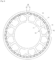
- FIG. 4 is a plan view illustrating both the stator and rotor in the motor according to the present invention.
- FIG. 5 is a plan view illustrating both the stator and rotor using a particular magnetization magnet in the motor according to the present invention.
- FIG. 1 is a plan view illustrating an embodiment of a stator 10 of a motor according to the present invention
- FIG. 2 is a plan view illustrating another embodiment of a stator of a motor according to the present invention
- a stator 10 of a motor includes a circular base 11 , a plurality of poles 12 radially formed in the circular base 11 , first and second teeth 13 and 14 with symmetrical shape at locations symmetrical to each other at the end of the pole, and a bridge 15 connecting the first and second teeth 13 and 14 .
- a stator or a stator assembly includes a stator core manufactured by laminating a plurality of thin steel plates, an insulator which insulates a base, pole and teeth of the stator core, and a coil wound in the insulated pole.
- a stator used herein may mean ‘a stator core’ or a case including the stator, insulator and coil. In the present specification, most of explanation on the insulator and coil will be omitted for the sake of convenience.
- a space between the pole 11 and its neighboring poles is a slot S.
- a size of one slot refers to a slit pitch Sp.
- Two teeth 13 and 14 are formed at the end of each pole 11 .
- the two teeth 13 and 14 are located with a constant distance therebetween.
- a distance between the teeth refers to a slot opening So.
- the present invention is not necessarily limited to those numbers.
- a stator including 6 poles and 12 teeth is possible, and a stator including 18 poles and 36 teeth is also possible.
- a form where two teeth are formed in one pole, that is, one pole including two teeth will be referred to as coupled teeth.
- These coupled teeth that is, the first and second teeth 13 and 14 , have symmetrical shape at locations which are symmetrical to each other.
- a ratio between the slot opening ( ⁇ So ) and slot pitch ( ⁇ Sp ) is 0.5, but the present invention is not necessarily limited thereto. When the ratio is formed in the range between 0.5 and 0.6, the vernier effect can be fully obtained.
- the bridge 15 is connected to the outer diameter portion of the pole 12 while connecting the inner diameter portion of the first teeth 13 and second teeth 14 .
- a shape of the bridge 15 also has a symmetrical shape with respect to the pole 12 .
- a shape of the outer diameter portion of the bridge 15 that is, the portion located at the slot opening So may have a circular arc shape as illustrated in FIG. 1 , or may have a straight line shape.
- a groove 15 a may be formed in the direction of inner diameter as illustrated in FIG. 2 . It is preferable that a depth of the groove 15 a is formed to the outer diameter portion of the pole 12 . By means of the groove 15 a , it is expected that an output would increase through the modulation effect.
- a shape or number of the groove 15 a may be modified in a various way other than the shape illustrated in FIG. 2 and applied.
- the stator 10 of the motor according to the present invention ties two teeth in one pole, so that the slot which is a space between the poles increases in size. Thus, it is advantageous to increase the number of coils.
- FIG. 3 is a conceptual diagram illustrating a relation between a stator 10 and a rotor magnet 21 in the motor according to the present invention
- FIG. 4 is a plan view illustrating both the stator 10 and rotor 20 in the motor according to the present invention.
- the motor according to the present invention includes the stator 10 and rotor 20 .
- the rotor 20 includes a cup-shaped rotor housing 21 in which the stator 10 is located inside, and a plurality of magnets 21 installed on the inner wall of the rotor housing 21 .
- the magnet 21 is located while facing the coupled teeth 13 and 14 of the stator 10 .
- a distance between the magnet 21 and an outer diameter surface of the teeth refers to an air-gap.
- a distance between the outer diameter portion of the bridge 15 which is the inner diameter portion of the slot opening, or the outer diameter portion of the base 11 and the magnet 21 also refers to an air-gap.
- a difference in permeance according to the air-gap is particularly considered for the vernier effect.
- a general ferrite permanent magnet for the magnet 21 .
- alnico magnet, neodymium magnet, samarium cobalt magnet, rubber magnet, etc. whose magnetic force, coercive force, etc. are different may be used.
- a general magnetization magnet magnetized only by north-seeking pole or south-seeking pole on the top surface and bottom surface may be used, or a particular magnetization magnet where north-seeking pole and south-seeking pole are consecutively magnetized together on the top surface or bottom surface may also be used.
- a single of or a plurality of pairs of north-seeking pole and south-seeking pole are magnetized on the top surface and bottom surface of the particular magnetization magnet.
- the number of magnets 21 is not specifically limited. However, in the case of a general magnetization magnet, it is preferable to use ten magnets per three slot pitches (3 ⁇ Sp ). In other words, when the distance between the pole and its neighboring poles is defined as the slot pitch, a ratio between the number of the magnets or the number of poles and the slot pitch is 10:3.
- a general magnetization magnet in the case of a motor with 12 slots and 36 teeth as illustrated in FIG. 3 and FIG. 4 , 40 magnets are used.
- 3 ⁇ Sp general magnetization magnets per three slot pitches
- the present invention is not limited to these numbers.
- 30 magnets are used in the case of a motor with 9 slots and 18 teeth.
- 60 magnets are used in the case of a motor with 18 slots and 36 teeth.
- the number of magnets is a suitable structure to obtain the vernier effect and may improve the output of the motor through the increase of counter electromotive force.
- the number of magnets may be reduced.
- the number of magnets 21 is 10.
- 20 magnets are used.
- a ratio between the number of magnets and the slot pitch becomes (10/(2n)):3 (Here, n refers to a natural number). In this case, a ratio between the number of poles of the magnet and the slot pitch becomes 10:3, like the general magnetization magnet.
Landscapes
- Engineering & Computer Science (AREA)
- Power Engineering (AREA)
- Iron Core Of Rotating Electric Machines (AREA)
Abstract
Description
Claims (6)
Applications Claiming Priority (3)
| Application Number | Priority Date | Filing Date | Title |
|---|---|---|---|
| KR10-2015-0185978 | 2015-12-24 | ||
| KR1020150185978A KR101751356B1 (en) | 2015-12-24 | 2015-12-24 | Motor having stator with coupled teeth |
| PCT/KR2016/011187 WO2017111267A1 (en) | 2015-12-24 | 2016-10-06 | Motor having stator with coupled teeth |
Publications (2)
| Publication Number | Publication Date |
|---|---|
| US20180323662A1 US20180323662A1 (en) | 2018-11-08 |
| US10622851B2 true US10622851B2 (en) | 2020-04-14 |
Family
ID=59090643
Family Applications (1)
| Application Number | Title | Priority Date | Filing Date |
|---|---|---|---|
| US15/774,280 Active 2036-12-09 US10622851B2 (en) | 2015-12-24 | 2016-10-06 | Motor having stator with coupled teeth |
Country Status (5)
| Country | Link |
|---|---|
| US (1) | US10622851B2 (en) |
| JP (1) | JP6767495B2 (en) |
| KR (1) | KR101751356B1 (en) |
| CN (1) | CN109417315B (en) |
| WO (1) | WO2017111267A1 (en) |
Families Citing this family (8)
| Publication number | Priority date | Publication date | Assignee | Title |
|---|---|---|---|---|
| JP2019013114A (en) * | 2017-06-30 | 2019-01-24 | 日本電産株式会社 | Brushless motor and blower |
| JP2019097349A (en) * | 2017-11-27 | 2019-06-20 | 日本電産株式会社 | Brushless motor, and air blower |
| US20200204026A1 (en) * | 2018-12-20 | 2020-06-25 | Massachusetts Institute Of Technology | Asymmetrical Winding Configuration For An Electric Motor Drive |
| KR20210068686A (en) * | 2019-12-02 | 2021-06-10 | 엘지전자 주식회사 | Vibration and noise reduction motor, rotor magnet structure of motor, and skew magnetizer yoke |
| CN111293799B (en) * | 2020-02-27 | 2022-10-28 | 南京奥特佳新能源科技有限公司 | Permanent magnet motor with optimized back electromotive force sine waveform and stator thereof |
| CN112688454B (en) * | 2020-12-15 | 2023-01-31 | 大连海事大学 | Permanent magnet fault-tolerant vernier rim propulsion motor with optimized surface shape of alternating-pole rotor |
| CN113572281A (en) * | 2021-08-04 | 2021-10-29 | 东南大学 | Low-speed large-torque motor stator |
| EP4246786A1 (en) * | 2022-03-18 | 2023-09-20 | TVS Motor Company Limited | A motor assembly |
Citations (9)
| Publication number | Priority date | Publication date | Assignee | Title |
|---|---|---|---|---|
| US4280072A (en) * | 1977-05-26 | 1981-07-21 | Matsushita Electric Industrial Co., Ltd. | Rotating electric machine |
| US4947066A (en) | 1988-11-01 | 1990-08-07 | Servo Products Co. | High speed variable reluctance motor with equal tooth ratios |
| JPH05111233A (en) | 1991-10-18 | 1993-04-30 | Japan Servo Co Ltd | Permanent magnet type stepping motor |
| JP2000197336A (en) | 1998-12-24 | 2000-07-14 | Oriental Motor Co Ltd | Five-phase permanent magnet type motor |
| US20010048264A1 (en) * | 2000-02-01 | 2001-12-06 | Pacsci Motion Control, Inc. | Brushless DC motor having reduced cogging torque |
| JP2003061326A (en) | 2001-08-08 | 2003-02-28 | Matsushita Electric Ind Co Ltd | Vernier-type brushless motor |
| US7143503B2 (en) | 2003-07-24 | 2006-12-05 | A. O. Smith Corporation | Brushless permanent magnet machine with axial modules of rotor magnetization skew and method of producing the same |
| KR20090067057A (en) | 2007-12-20 | 2009-06-24 | 삼성전자주식회사 | Brushless motor |
| CN105071620A (en) * | 2015-08-26 | 2015-11-18 | 江苏大学 | Embedded permanent-magnet fault-tolerant type vernier motor having flux concentrator effect |
Family Cites Families (4)
| Publication number | Priority date | Publication date | Assignee | Title |
|---|---|---|---|---|
| BR0004133A (en) * | 1999-04-16 | 2001-01-09 | Newage Int Ltd | Alternating current machine |
| CN202713100U (en) * | 2012-06-13 | 2013-01-30 | 江苏大学 | Low-speed and large-torque five-phase permanent magnetism fault tolerance motor for electromobile |
| CN103490534B (en) * | 2013-09-27 | 2016-06-29 | 江苏大学 | A kind of stator permanent magnetic type vernier motor structure reducing detent force |
| CN103795159B (en) * | 2014-01-03 | 2016-02-10 | 东南大学 | The two permanent-magnet type vernier motor of rotor |
-
2015
- 2015-12-24 KR KR1020150185978A patent/KR101751356B1/en active IP Right Grant
-
2016
- 2016-10-06 US US15/774,280 patent/US10622851B2/en active Active
- 2016-10-06 WO PCT/KR2016/011187 patent/WO2017111267A1/en active Application Filing
- 2016-10-06 CN CN201680069726.8A patent/CN109417315B/en active Active
- 2016-10-06 JP JP2018545096A patent/JP6767495B2/en active Active
Patent Citations (13)
| Publication number | Priority date | Publication date | Assignee | Title |
|---|---|---|---|---|
| US4280072A (en) * | 1977-05-26 | 1981-07-21 | Matsushita Electric Industrial Co., Ltd. | Rotating electric machine |
| US4947066A (en) | 1988-11-01 | 1990-08-07 | Servo Products Co. | High speed variable reluctance motor with equal tooth ratios |
| JPH05111233A (en) | 1991-10-18 | 1993-04-30 | Japan Servo Co Ltd | Permanent magnet type stepping motor |
| US5289064A (en) | 1991-10-18 | 1994-02-22 | Japan Servo Co., Ltd. | Three-phase permanent magnet stepping motor |
| JP2000197336A (en) | 1998-12-24 | 2000-07-14 | Oriental Motor Co Ltd | Five-phase permanent magnet type motor |
| US20010048264A1 (en) * | 2000-02-01 | 2001-12-06 | Pacsci Motion Control, Inc. | Brushless DC motor having reduced cogging torque |
| JP2003061326A (en) | 2001-08-08 | 2003-02-28 | Matsushita Electric Ind Co Ltd | Vernier-type brushless motor |
| US20040245887A1 (en) | 2001-08-08 | 2004-12-09 | Hiroyasu Fujinaka | Brush-less motor using vernier structure |
| US7143503B2 (en) | 2003-07-24 | 2006-12-05 | A. O. Smith Corporation | Brushless permanent magnet machine with axial modules of rotor magnetization skew and method of producing the same |
| KR20090067057A (en) | 2007-12-20 | 2009-06-24 | 삼성전자주식회사 | Brushless motor |
| US20090160287A1 (en) * | 2007-12-20 | 2009-06-25 | Samsung Electronics Co., Ltd. | Brushless motor |
| JP2009153305A (en) | 2007-12-20 | 2009-07-09 | Samsung Electronics Co Ltd | Brushless motor |
| CN105071620A (en) * | 2015-08-26 | 2015-11-18 | 江苏大学 | Embedded permanent-magnet fault-tolerant type vernier motor having flux concentrator effect |
Non-Patent Citations (3)
| Title |
|---|
| Byungtaek Kim et al., "Operation and Design Principles of a PM Vernier Motor", IEEE Transactions on Industry Applications, vol. 50, No. 6, Nov./Dec. 2014, pp. 3656-3663. |
| International Search Report for PCT/KR2016/011187 dated Jan. 9, 2017 from Korean Intellectual Property Office. |
| Machine Translation, Zhao, CN-105071620-A, Nov. 2015. (Year: 2015). * |
Also Published As
| Publication number | Publication date |
|---|---|
| JP6767495B2 (en) | 2020-10-14 |
| WO2017111267A1 (en) | 2017-06-29 |
| CN109417315B (en) | 2021-04-30 |
| KR101751356B1 (en) | 2017-06-27 |
| JP2018535644A (en) | 2018-11-29 |
| CN109417315A (en) | 2019-03-01 |
| US20180323662A1 (en) | 2018-11-08 |
Similar Documents
| Publication | Publication Date | Title |
|---|---|---|
| US10622851B2 (en) | Motor having stator with coupled teeth | |
| US9331532B2 (en) | Permanent magnet rotor brushless motor | |
| US20170338726A1 (en) | Polyphase motor having an alternation of permanent magnets and salient poles | |
| JP2012228104A (en) | Permanent magnet-embedded motor | |
| JP2013188131A (en) | Permanent magnet motor | |
| US9762097B2 (en) | Rotor and motor | |
| EP2626976A2 (en) | Rotary electric machine | |
| CN104702004B (en) | Electric motor | |
| JP2014171368A (en) | Inductor type rotary motor | |
| JP5307849B2 (en) | Electric motor | |
| KR20130035707A (en) | Switched reluctance motor | |
| CN110277889B (en) | Stator permanent magnet type rotary transformer | |
| KR101614685B1 (en) | Wound field type synchronous motor and rotor thereof | |
| US11901773B2 (en) | Rotating electric machine | |
| KR101597966B1 (en) | Interior permanent magnet synchronous motor adding transverse air-gap | |
| JP6950361B2 (en) | motor | |
| KR102246697B1 (en) | Axial Flux Permanent Magnet generator | |
| KR20190074467A (en) | A Motor having split stator | |
| JP6451517B2 (en) | Rotor | |
| JP2013207920A (en) | Permanent magnet type rotary electrical machine | |
| US9018815B2 (en) | Generator | |
| JP6582432B2 (en) | Multi-rundel motor | |
| KR20160112611A (en) | Rotor and motor comprising the same | |
| JP2014161206A (en) | Interior magnet type rotating electrical machine | |
| KR20140023126A (en) | Rotor of interior permanent magnet synchronous motor and interior permanent magnet synchronous motor having the same |
Legal Events
| Date | Code | Title | Description |
|---|---|---|---|
| AS | Assignment |
Owner name: INDUSTRY ACADEMIC COOPERATION FOUNDATION, KUNSAN NATIONAL UNIVERSITY, KOREA, REPUBLIC OF Free format text: ASSIGNMENT OF ASSIGNORS INTEREST;ASSIGNORS:JANG, JEONG CHEOL;LEE, JI MIN;YANG, GYEONG SIK;AND OTHERS;SIGNING DATES FROM 20180413 TO 20180430;REEL/FRAME:045736/0757 Owner name: INDUSTRY ACADEMIC COOPERATION FOUNDATION, KUNSAN N Free format text: ASSIGNMENT OF ASSIGNORS INTEREST;ASSIGNORS:JANG, JEONG CHEOL;LEE, JI MIN;YANG, GYEONG SIK;AND OTHERS;SIGNING DATES FROM 20180413 TO 20180430;REEL/FRAME:045736/0757 Owner name: NEW MOTECH CO., LTD., KOREA, REPUBLIC OF Free format text: ASSIGNMENT OF ASSIGNORS INTEREST;ASSIGNORS:JANG, JEONG CHEOL;LEE, JI MIN;YANG, GYEONG SIK;AND OTHERS;SIGNING DATES FROM 20180413 TO 20180430;REEL/FRAME:045736/0757 |
|
| FEPP | Fee payment procedure |
Free format text: ENTITY STATUS SET TO UNDISCOUNTED (ORIGINAL EVENT CODE: BIG.); ENTITY STATUS OF PATENT OWNER: SMALL ENTITY |
|
| FEPP | Fee payment procedure |
Free format text: ENTITY STATUS SET TO SMALL (ORIGINAL EVENT CODE: SMAL); ENTITY STATUS OF PATENT OWNER: SMALL ENTITY |
|
| STPP | Information on status: patent application and granting procedure in general |
Free format text: APPLICATION DISPATCHED FROM PREEXAM, NOT YET DOCKETED |
|
| STPP | Information on status: patent application and granting procedure in general |
Free format text: DOCKETED NEW CASE - READY FOR EXAMINATION |
|
| STPP | Information on status: patent application and granting procedure in general |
Free format text: NON FINAL ACTION MAILED |
|
| STPP | Information on status: patent application and granting procedure in general |
Free format text: RESPONSE TO NON-FINAL OFFICE ACTION ENTERED AND FORWARDED TO EXAMINER |
|
| STPP | Information on status: patent application and granting procedure in general |
Free format text: NOTICE OF ALLOWANCE MAILED -- APPLICATION RECEIVED IN OFFICE OF PUBLICATIONS |
|
| STCF | Information on status: patent grant |
Free format text: PATENTED CASE |
|
| MAFP | Maintenance fee payment |
Free format text: PAYMENT OF MAINTENANCE FEE, 4TH YR, SMALL ENTITY (ORIGINAL EVENT CODE: M2551); ENTITY STATUS OF PATENT OWNER: SMALL ENTITY Year of fee payment: 4 |