US10620599B2 - Distributed finite state machine configuration for controlling a physical asset - Google Patents
Distributed finite state machine configuration for controlling a physical asset Download PDFInfo
- Publication number
- US10620599B2 US10620599B2 US15/862,367 US201815862367A US10620599B2 US 10620599 B2 US10620599 B2 US 10620599B2 US 201815862367 A US201815862367 A US 201815862367A US 10620599 B2 US10620599 B2 US 10620599B2
- Authority
- US
- United States
- Prior art keywords
- level controller
- state machine
- finite state
- low
- states
- Prior art date
- Legal status (The legal status is an assumption and is not a legal conclusion. Google has not performed a legal analysis and makes no representation as to the accuracy of the status listed.)
- Active, expires
Links
- 238000010248 power generation Methods 0.000 claims abstract description 58
- 238000004891 communication Methods 0.000 claims abstract description 34
- 238000000034 method Methods 0.000 claims description 23
- 230000007704 transition Effects 0.000 claims description 7
- 239000000446 fuel Substances 0.000 claims description 6
- 239000000203 mixture Substances 0.000 claims description 5
- 239000000498 cooling water Substances 0.000 claims description 4
- 239000000567 combustion gas Substances 0.000 description 3
- 230000005611 electricity Effects 0.000 description 3
- 230000007257 malfunction Effects 0.000 description 3
- 238000012986 modification Methods 0.000 description 3
- 230000004048 modification Effects 0.000 description 3
- 230000002411 adverse Effects 0.000 description 2
- 230000008878 coupling Effects 0.000 description 2
- 238000010168 coupling process Methods 0.000 description 2
- 238000005859 coupling reaction Methods 0.000 description 2
- 238000005516 engineering process Methods 0.000 description 2
- 230000006870 function Effects 0.000 description 2
- 238000012544 monitoring process Methods 0.000 description 2
- 230000003287 optical effect Effects 0.000 description 2
- 230000004044 response Effects 0.000 description 2
- 230000008901 benefit Effects 0.000 description 1
- 230000002457 bidirectional effect Effects 0.000 description 1
- 238000012217 deletion Methods 0.000 description 1
- 230000037430 deletion Effects 0.000 description 1
- 238000001514 detection method Methods 0.000 description 1
- 238000011161 development Methods 0.000 description 1
- 230000018109 developmental process Effects 0.000 description 1
- 238000013021 overheating Methods 0.000 description 1
- 230000003449 preventive effect Effects 0.000 description 1
- 230000008569 process Effects 0.000 description 1
- 230000008439 repair process Effects 0.000 description 1
- 230000003252 repetitive effect Effects 0.000 description 1
- 230000011664 signaling Effects 0.000 description 1
- 230000003068 static effect Effects 0.000 description 1
Images


Classifications
-
- G—PHYSICS
- G05—CONTROLLING; REGULATING
- G05B—CONTROL OR REGULATING SYSTEMS IN GENERAL; FUNCTIONAL ELEMENTS OF SUCH SYSTEMS; MONITORING OR TESTING ARRANGEMENTS FOR SUCH SYSTEMS OR ELEMENTS
- G05B19/00—Programme-control systems
- G05B19/02—Programme-control systems electric
- G05B19/04—Programme control other than numerical control, i.e. in sequence controllers or logic controllers
- G05B19/042—Programme control other than numerical control, i.e. in sequence controllers or logic controllers using digital processors
- G05B19/0421—Multiprocessor system
-
- G—PHYSICS
- G05—CONTROLLING; REGULATING
- G05B—CONTROL OR REGULATING SYSTEMS IN GENERAL; FUNCTIONAL ELEMENTS OF SUCH SYSTEMS; MONITORING OR TESTING ARRANGEMENTS FOR SUCH SYSTEMS OR ELEMENTS
- G05B19/00—Programme-control systems
- G05B19/02—Programme-control systems electric
- G05B19/04—Programme control other than numerical control, i.e. in sequence controllers or logic controllers
- G05B19/045—Programme control other than numerical control, i.e. in sequence controllers or logic controllers using logic state machines, consisting only of a memory or a programmable logic device containing the logic for the controlled machine and in which the state of its outputs is dependent on the state of its inputs or part of its own output states, e.g. binary decision controllers, finite state controllers
-
- G—PHYSICS
- G05—CONTROLLING; REGULATING
- G05B—CONTROL OR REGULATING SYSTEMS IN GENERAL; FUNCTIONAL ELEMENTS OF SUCH SYSTEMS; MONITORING OR TESTING ARRANGEMENTS FOR SUCH SYSTEMS OR ELEMENTS
- G05B23/00—Testing or monitoring of control systems or parts thereof
- G05B23/02—Electric testing or monitoring
- G05B23/0205—Electric testing or monitoring by means of a monitoring system capable of detecting and responding to faults
- G05B23/0259—Electric testing or monitoring by means of a monitoring system capable of detecting and responding to faults characterized by the response to fault detection
- G05B23/0286—Modifications to the monitored process, e.g. stopping operation or adapting control
- G05B23/0291—Switching into safety or degraded mode, e.g. protection and supervision after failure
-
- G—PHYSICS
- G05—CONTROLLING; REGULATING
- G05B—CONTROL OR REGULATING SYSTEMS IN GENERAL; FUNCTIONAL ELEMENTS OF SUCH SYSTEMS; MONITORING OR TESTING ARRANGEMENTS FOR SUCH SYSTEMS OR ELEMENTS
- G05B9/00—Safety arrangements
- G05B9/02—Safety arrangements electric
- G05B9/03—Safety arrangements electric with multiple-channel loop, i.e. redundant control systems
-
- G—PHYSICS
- G06—COMPUTING; CALCULATING OR COUNTING
- G06F—ELECTRIC DIGITAL DATA PROCESSING
- G06F9/00—Arrangements for program control, e.g. control units
- G06F9/06—Arrangements for program control, e.g. control units using stored programs, i.e. using an internal store of processing equipment to receive or retain programs
- G06F9/44—Arrangements for executing specific programs
- G06F9/448—Execution paradigms, e.g. implementations of programming paradigms
- G06F9/4498—Finite state machines
-
- G—PHYSICS
- G05—CONTROLLING; REGULATING
- G05B—CONTROL OR REGULATING SYSTEMS IN GENERAL; FUNCTIONAL ELEMENTS OF SUCH SYSTEMS; MONITORING OR TESTING ARRANGEMENTS FOR SUCH SYSTEMS OR ELEMENTS
- G05B2219/00—Program-control systems
- G05B2219/20—Pc systems
- G05B2219/22—Pc multi processor system
- G05B2219/2231—Master slave
-
- G—PHYSICS
- G05—CONTROLLING; REGULATING
- G05B—CONTROL OR REGULATING SYSTEMS IN GENERAL; FUNCTIONAL ELEMENTS OF SUCH SYSTEMS; MONITORING OR TESTING ARRANGEMENTS FOR SUCH SYSTEMS OR ELEMENTS
- G05B2219/00—Program-control systems
- G05B2219/20—Pc systems
- G05B2219/23—Pc programming
- G05B2219/23289—State logic control, finite state, tasks, machine, fsm
-
- G—PHYSICS
- G05—CONTROLLING; REGULATING
- G05B—CONTROL OR REGULATING SYSTEMS IN GENERAL; FUNCTIONAL ELEMENTS OF SUCH SYSTEMS; MONITORING OR TESTING ARRANGEMENTS FOR SUCH SYSTEMS OR ELEMENTS
- G05B2219/00—Program-control systems
- G05B2219/20—Pc systems
- G05B2219/24—Pc safety
- G05B2219/24177—State machine arbitrates which redundant controller is active
-
- G—PHYSICS
- G05—CONTROLLING; REGULATING
- G05B—CONTROL OR REGULATING SYSTEMS IN GENERAL; FUNCTIONAL ELEMENTS OF SUCH SYSTEMS; MONITORING OR TESTING ARRANGEMENTS FOR SUCH SYSTEMS OR ELEMENTS
- G05B2219/00—Program-control systems
- G05B2219/20—Pc systems
- G05B2219/25—Pc structure of the system
- G05B2219/25484—Synchronize microprocessor and connected, controlled state machine
-
- G—PHYSICS
- G05—CONTROLLING; REGULATING
- G05B—CONTROL OR REGULATING SYSTEMS IN GENERAL; FUNCTIONAL ELEMENTS OF SUCH SYSTEMS; MONITORING OR TESTING ARRANGEMENTS FOR SUCH SYSTEMS OR ELEMENTS
- G05B2219/00—Program-control systems
- G05B2219/30—Nc systems
- G05B2219/33—Director till display
- G05B2219/33343—Each slave stores communication program to be used by master, exchangeability
Definitions
- This disclosure generally relates to controlling a physical asset, and more particularly, to using a distributed finite machine configuration for controlling a physical asset such as a power generation unit.
- Electric power is typically generated in a power plant by using one or more power generation units.
- a typical power generation unit can include a compressor that provides pressurized air to a combustor where the pressurized air is mixed with fuel and ignited for producing hot combustion gases.
- the hot combustion gases flow downstream from the combustor and into a turbine where energy is extracted from the hot combustion gases in order to rotate rotor blades that are attached to a shaft.
- the rotation of the shaft can be used to generate electricity in an electric generator and the generated electricity coupled into an electric grid for distribution to customers.
- Embodiments of the disclosure are directed generally to systems and methods incorporating multi-level controllers that cooperate with each other to execute a distributed finite state machine configuration allows continuous control of a power generation unit.
- a system can include a high-level controller and a low-level controller.
- the high-level controller is in communication with a physical asset via a network through a network connection and is configured to execute a first finite state machine for controlling the physical asset during a normal mode of operation.
- the low-level controller is configured to execute a second finite state machine for controlling the physical asset during a default mode of operation, the second finite state machine configured to place the low-level controller in the default mode of operation upon detecting a loss of communications between the high-level controller and the low-level controller.
- a method can include utilizing a high-level controller to execute a first finite state machine for controlling a physical asset during a normal mode of operation.
- the method can also include utilizing a low-level controller that is configured to execute a second finite state machine for controlling the physical asset during a default mode of operation; detecting a loss of communication between the high-level controller and the low-level controller; and placing the low-level controller in the default mode of operation upon detecting the loss of communication between the high-level controller and the low-level controller.
- a method can include utilizing a high-level controller configured to execute a first finite state machine for placing a physical asset in one of a first set of operational states; providing a low-level controller comprising a second finite state machine that is executable for placing the physical asset in one of a second set of operational states that is smaller than the first set of operational states; detecting a loss of communication between the high-level controller and the low-level controller; and executing the second finite state machine for placing the physical asset in the one of the second set of operational states upon detecting the loss of communication between the high-level controller and the low-level controller.
- FIG. 1 illustrates an exemplary system that uses multi-level controllers for controlling one or more physical assets in accordance with an exemplary embodiment of the disclosure.
- FIG. 2 illustrates some exemplary multi-level controllers that utilize a distributed finite state machine configuration for controlling a power generation unit in accordance with an exemplary embodiment of the disclosure.
- FIG. 3 shows a pair of exemplary finite state machines that can be a part of the distributed finite state machine configuration illustrated in FIG. 2 .
- FIG. 4 shows a first exemplary flowchart of a method of utilizing the pair of finite state machines shown in FIG. 3 .
- FIG. 5 shows a second exemplary flowchart of a method of utilizing the pair of finite state machines shown in FIG. 3 .
- FIG. 6 illustrates some exemplary elements that can be included in a computer configured to execute a first exemplary finite state machine in accordance with an exemplary embodiment of the disclosure.
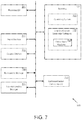
- FIG. 7 illustrates some exemplary elements that can be included in a computer configured to execute a second exemplary finite state machine in accordance with an exemplary embodiment of the disclosure.
- certain embodiments described in this disclosure pertain to a system having a high-level controller that can be coupled to one or more low-level controllers in an arrangement that allows the high-level controller to cooperate with the low-level controller for controlling a physical asset such as a power generation unit.
- the high-level controller executes a first finite state machine for controlling a power generation unit via a network during a normal mode of operation.
- the low-level controller executes a second finite state machine that may have fewer states than the first finite state machine.
- the second finite state machine places the low-level controller in a default mode of operation under one or more of various conditions.
- Some examples of these various conditions are: when the high-level controller is controlling the physical asset during the normal mode of operation; when the high-level controller is revising the first finite state machine; when the high-level controller is controlling the physical asset by utilizing a revised first finite state machine; and/or upon detecting a loss of communications between the high-level controller and the low-level controller.
- FIG. 1 illustrates an exemplary system 100 that provides for using a multi-level controller system having a distributed finite state machine configuration for controlling one or more of physical assets in accordance with an exemplary embodiment of the disclosure.
- the exemplary system 100 can include a high-level controller 105 that is communicatively coupled to one or more of low-level controllers, such as a first low-level controller 115 , a second low-level controller 120 , and an “n th ” low-level controller 125 (n>1).
- the high-level controller 105 can be communicatively coupled to a single low-level controller.
- Each of the low-level controllers can be coupled to one or more actuators that actuate one or more controls (such as a temperature control, a fuel-feed control etc.) of an associated physical asset.
- each of a first physical asset 155 , a second physical asset 160 , and an “n th ” physical asset 175 (n>1) is a power generation unit.
- the description hereon refers to the first low-level controller 115 and the physical asset 165 but it should be understood that the description applies equally well to the other low-level controllers and assets.
- the physical asset 165 may be referred to in some instances as a power generation unit, which is one example of a physical asset that can be operated upon in accordance with various exemplary embodiments of the disclosure.
- the communications network 110 used to provide the communicative coupling between the high-level controller 105 and the one or more low-level controllers can be any one or more of various types of networks such as the Internet, a private wide-area network (WAN), or a private local area network (LAN).
- the communications network 110 can also be used to provide the communicative coupling between the high-level controller 105 and one or more of the “n” physical assets.
- the high-level controller 105 can be a server computer configured to execute one or more software programs for controlling the various assets via the communications network 110 .
- An exemplary software program incorporates a first finite state machine that can be used to operate the physical asset 165 .
- the high-level controller 105 may allow the first finite state machine to be modified for operating the physical asset 165 in various ways. The modifications may be carried out for various reasons such as for improving the performance of the physical asset 165 based on new developments or studies for example. Consequently, the high-level controller 105 may be taken offline or shut down during the process of modifying the software program incorporating the first finite state machine.
- the low-level controller 115 can be a client computer configured to execute one or more software programs.
- An exemplary software program executed by the low-level controller 115 incorporates a second finite state machine directed at ensuring that the physical asset 165 has a high mean time between failures (MTBF).
- the low-level controller 115 may include hardware which is highly reliable but may be outdated in some cases.
- the software may also be outdated. Both the hardware and the software may be selected to prevent the low-level controller 115 from being taken offline or shut down other than in extraordinary circumstances (such as a hardware failure or a natural disaster) so as to avoid malfunctioning of the physical asset 165 .
- FIG. 2 illustrates an exemplary system 200 that uses a distributed finite state machine configuration to control a power generation unit 215 in accordance with an exemplary embodiment of the disclosure.
- the exemplary system 200 can include the high-level controller 105 communicatively coupled to the low-level controller 115 via the communications network 110 .
- the low-level controller 115 is communicatively coupled to the actuator 130 .
- the actuator 130 which can be one of several actuators, is communicatively coupled to the power generation unit 215 for controlling various components of the power generation unit 215 in response to commands provided by the low-level controller 115 .
- the low-level controller 115 utilizes a software program incorporating the second finite state machine 210 for providing the commands to the actuator 130 .
- the high-level controller 105 is also communicatively coupled to the actuator 130 via the communications network 110 , thereby having the capability to bypass the low-level controller 115 .
- the high-level controller 105 utilizes a software program incorporating the first finite state machine 205 for providing commands to the actuator 130 .
- the high-level controller 105 controls the power generation unit 215 during a normal mode of operation.
- the low-level controller 115 is configured to yield control to the high-level controller 105 and refrain from providing control signals to the actuator 130 .
- the low-level controller 115 is further configured to detect any failure on the part of the high-level controller 105 when the high-level controller 105 is controlling the power generation unit 215 .
- the high-level controller 105 is configured to transmit a heartbeat signal to the low-level controller 115 .
- the heartbeat signal can be a message or other means of signaling that is transmitted repetitively (for example, every minute) to the low-level controller 115 by a synchronizer 220 in the high-level controller 105 .
- the low-level controller 115 monitors the heartbeat signal and recognizes that the presence of the heartbeat signal is indicative of the high-level controller 105 controlling the power generation unit 215 .
- the low-level controller 115 upon detecting a loss of the heartbeat signal, assumes that the high-level controller 105 is no longer controlling the power generation unit 215 and consequently, takes over control of the power generation unit 215 in what can be referred to as a default mode of operation.
- the heartbeat signal may be lost for a variety of reasons such as due to a failure or malfunction in the high-level controller 105 , failure or malfunction of one or more devices in the communications network 110 , or may be intentionally stopped by the high-level controller 105 .
- the high-level controller 105 stops transmitting of the heartbeat signal to the low-level controller 115 in order to carry out changes in hardware or software in the high-level controller 105 .
- Changes in the software can include addition and/or deletion of one or more states in the first finite state machine 205 .
- the low-level controller 115 has to ensure that the software program incorporating the second finite state machine 210 seamlessly assumes control of the power generation unit 215 .
- FIG. 3 illustrates the first finite state machine 205 and the second finite state machine 210 configured to allow the high-level controller 105 to control the power generation unit 215 during the normal mode of operation and ensure that the low-level controller 115 seamlessly assumes control of the power generation unit 215 during the default mode of operation when the high-level controller 105 is not controlling the power generation unit 215 .
- the first finite state machine 205 includes a first set of states for controlling a first number of operational aspects of the power generation unit 215 .
- Each state can represent various control conditions.
- state A may represent controls and monitoring parameters associated with a first air-fuel mixture provided for operating the power generation unit 215 .
- State B may represent controls and monitoring parameters associated with providing cooling water in the power generation unit 215 .
- a transition from state A to state B may take place when the software program determines that a component of the power generation unit 215 is overheating as a result of the first air-fuel mixture provided when in state A.
- the bidirectional solid lines indicate various other such transitions that may take place between state A, state B, state C, and state D.
- the software program incorporating a combination of state A, state B, state C, and state D represents a stable software program that may have been used over a long period of time to control the power generation unit 215 .
- the software program incorporating the combination of state A, state B, state C, and state D may be mirrored in the second finite state machine 210 that is used by a software program executed in the low-level controller 115 .
- the synchronizer 220 in the high-level controller 105 provides the heartbeat signal to the low-level controller 115 to indicate to the low-level controller 115 that the high-level controller 105 is operating in the normal mode of operation.
- the synchronizer 220 also provides suitable updates to the low-level controller 115 to ensure that the combination of state A, state B, state C, and state D in the high-level controller 105 is accurately mirrored in the second finite state machine 210 .
- the first finite state machine 205 may not be identical to the second finite state machine 210 .
- the software program in the high-level controller 105 may undergo a revision of the first finite state machine 205 for introducing some changes in the manner by which the high-level controller 105 controls the power generation unit 215 and/or for providing control of a second number of operational aspects of the power generation unit 215 that may be larger than the first number of operational aspects controllable by the first finite state machine 205 .
- the changes in the software program in the high-level controller 105 are indicated by dashed lines in the first finite state machine 205 .
- a new state E has been introduced and a new conditional jump introduced from state A to state D.
- the new state E may be arrived at from either state A or state C.
- State E may represent, for example, a control operation for improving an MTBF of the power generation unit 215 .
- a trial execution of the software program incorporating the revised first finite state machine 205 may encounter a failure after transitioning from state A to state E for example.
- Operations of the power generation unit 215 may be adversely affected if no preventive measures are in place to respond to this failure, because the software program running in the low-level controller 115 may be unable to seamlessly take over control of the power generation unit 215 as a result of lacking state E in the second finite state machine 210 .
- the power generation unit 215 may be operating in response to state E in the first finite state machine 205 , and the second finite state machine 210 may ineffectively and/or improperly attempt to use state A during the default mode of operation.
- Such an adverse condition is addressed in accordance with the disclosure by using the synchronizer 220 to provide configuration information to the low-level controller 115 for configuring the second finite state machine 210 to transition from state A or state C to a default state S when the first finite state machine 205 is executing state E. Consequently, when a failure occurs during execution of state E of the first finite state machine 205 , the second finite state machine 210 is in the default state S and can transition from the default state S into one of the other states. This operation may be carried out by using sensors (not shown) to identify various operating conditions of the power generation unit 215 .
- the configuration information provided by the synchronizer 220 to the low-level controller 115 can be carried out on a recurring basis, such as for example, on a periodically repetitive basis (seconds, minutes, hours etc.) or can be carried out on an as-needed basis, for example, prior to carrying out one or more changes upon the first finite state machine 205 .
- a failure in the execution of the revised first finite state machine 205 may be detected in the low-level controller 115 by various ways such as by a failure to receive the heartbeat signal, or a failure to receive one or more messages from the high-level controller 105 .
- FIG. 4 shows an exemplary flowchart of a method 400 of utilizing the first finite state machine 205 cooperatively with the second finite state machine 210 to control a physical asset in accordance with an exemplary embodiment of the disclosure.
- the high-level controller 105 is configured to execute the first finite state machine 205 for controlling a physical asset, such as the power generation unit 215 , during a normal mode of operation.
- the low-level controller 115 is configured to execute the second finite state machine 210 for controlling the power generation unit 215 during a default mode of operation.
- a loss of communication is detected between the high-level controller 105 and the low-level controller 115 .
- This operation may be carried out by detecting loss of a heartbeat signal in the low-level controller 115 .
- the low-level controller 115 is placed in the default mode of operation upon detecting the loss of communication between the high-level controller 105 and the low-level controller 115 .
- FIG. 5 shows another exemplary flowchart of a method 500 of utilizing the first finite state machine 205 cooperatively with the second finite state machine 210 to control a physical asset in accordance with an exemplary embodiment of the disclosure.
- the high-level controller 105 is utilized to execute the first finite state machine 205 for placing the power generation unit 215 in one of a first set of operational states.
- the low-level controller 115 that includes the second finite state machine 210 is provided for placing the power generation unit 215 in one of a second set of operational states.
- the second set of operational states can be smaller than the first set of operational states.
- a loss of communication is detected between the high-level controller 105 and the low-level controller 115 .
- This operation may be carried out by detecting loss of a heartbeat signal in the low-level controller 115 .
- the second finite state machine 210 is executed for placing the power generation unit 215 in one of the second set of operational states upon detecting the loss of communication between the high-level controller 105 and the low-level controller 115 .
- FIG. 6 illustrates some exemplary elements that can be included in a computer configured to execute the high-level controller 105 having the first finite state machine 205 in accordance with an exemplary embodiment of the disclosure. It should be understood that in various exemplary embodiments, the high-level controller 105 may be configured as a server computer. Accordingly, some of the hardware elements described below with reference to FIG. 6 may be omitted and other elements that are typically used for operating a server computer may be used instead.
- the high-level controller 105 may include a processor 605 capable of communicating with a memory 625 .
- the processor 605 may be implemented as appropriate in hardware, software, firmware, or combinations thereof.
- Software or firmware implementations of the processor 605 may include computer-executable or machine-executable instructions written in any suitable programming language to perform the various functions described.
- instructions associated with a function block language may be stored in the memory 625 and executed by the processor 605 .
- the memory 625 may store program instructions that are loadable and executable on the processor 605 , as well as data generated during the execution of these programs.
- the memory 625 may be volatile (such as random access memory (RAM)) and/or non-volatile (such as read-only memory (ROM), flash memory, etc.).
- the high-level controller 105 may also include additional removable storage 630 and/or non-removable storage 635 including, but not limited to, magnetic storage, optical disks, and/or tape storage.
- the memory 625 and associated computer-readable media may provide non-volatile storage of computer-readable instructions, data structures, program modules, and other data for the devices.
- the memory 625 may include multiple different types of memory, such as static random access memory (SRAM), dynamic random access memory (DRAM), or ROM.
- SRAM static random access memory
- DRAM dynamic random access memory
- ROM read-only memory
- Non-transitory computer-readable storage media may include volatile and non-volatile, removable and non-removable media implemented in any method or technology for storage of information such as computer-readable instructions, data structures, program modules or other data.
- non-transitory computer storage media include, but are not limited to, programmable random access memory (PRAM), SRAM, DRAM, RAM, ROM, electrically erasable programmable read-only memory (EEPROM), flash memory or other memory technology, compact disc read-only memory (CD-ROM), digital versatile discs (DVD) or other optical storage, magnetic cassettes, magnetic tapes, magnetic disk storage or other magnetic storage devices, or any other medium which can be used to store the desired information and which can be accessed by the devices. Combinations of any of the above should also be included within the scope of non-transitory computer-readable media.
- the high-level controller 105 may also include one or more communication connections 610 that may allow the high-level controller 105 to communicate with devices or equipment capable of communicating with the high-level controller 105 .
- the connections can be established via various data communication channels or ports, such as USB or COM ports to receive connections for cables connecting a control device to various other devices on a network, such as the communications network 110 .
- the high-level controller 105 may include Ethernet drivers that enable the high-level controller 105 to communicate with other devices.
- the communication connections 610 may be established via one or more wired and/or wireless connection.
- the high-level controller 105 may also include one or more input devices 615 , such as a keyboard, mouse, pen, voice input device, and touch input device.
- the high-level controller 105 may further include one or more output devices 620 , such as a display, printer, and speakers.
- the memory 625 may include, but is not limited to, an operating system (OS) 626 (such as may be used in a server computer) and one or more application programs or services for implementing the features and aspects disclosed herein with reference to the high-level controller 105 .
- OS operating system
- application programs or services may include high-level controller software 627 .
- the high-level controller software 627 may include the finite state machine 205 and the synchronizer 220 executable by the processor 605 for providing functionalities described herein.
- FIG. 7 illustrates some exemplary elements that can be included in a computer configured to execute the high-level controller 105 having the first finite state machine 205 in accordance with an exemplary embodiment of the disclosure.
- the processor 705 , input devices 715 , output devices 720 , removable storage 730 , and non-removable storage 735 , and communication connection(s) 710 that are shown in FIG. 7 are identical or substantially similar to corresponding elements shown in FIG. 6 and described above. Consequently, these elements will not be described here.
- the memory 725 may include, but is not limited to, an operating system (OS) 726 (such as may be used in a client computer) and one or more application programs or services for implementing the features and aspects disclosed herein with reference to the low-level controller 115 .
- Such applications or services may include the second finite state machine 210 that is executable by the processor 705 for providing functionalities described herein.
Landscapes
- Engineering & Computer Science (AREA)
- Physics & Mathematics (AREA)
- General Physics & Mathematics (AREA)
- Automation & Control Theory (AREA)
- Software Systems (AREA)
- Theoretical Computer Science (AREA)
- General Engineering & Computer Science (AREA)
- Remote Monitoring And Control Of Power-Distribution Networks (AREA)
- Safety Devices In Control Systems (AREA)
- Testing And Monitoring For Control Systems (AREA)
Abstract
Description
Claims (20)
Priority Applications (2)
| Application Number | Priority Date | Filing Date | Title |
|---|---|---|---|
| US15/862,367 US10620599B2 (en) | 2018-01-04 | 2018-01-04 | Distributed finite state machine configuration for controlling a physical asset |
| EP18215297.5A EP3508929B1 (en) | 2018-01-04 | 2018-12-21 | Distributed finite state machine configuration for controlling a physical asset |
Applications Claiming Priority (1)
| Application Number | Priority Date | Filing Date | Title |
|---|---|---|---|
| US15/862,367 US10620599B2 (en) | 2018-01-04 | 2018-01-04 | Distributed finite state machine configuration for controlling a physical asset |
Publications (2)
| Publication Number | Publication Date |
|---|---|
| US20190204802A1 US20190204802A1 (en) | 2019-07-04 |
| US10620599B2 true US10620599B2 (en) | 2020-04-14 |
Family
ID=65009569
Family Applications (1)
| Application Number | Title | Priority Date | Filing Date |
|---|---|---|---|
| US15/862,367 Active 2038-01-11 US10620599B2 (en) | 2018-01-04 | 2018-01-04 | Distributed finite state machine configuration for controlling a physical asset |
Country Status (2)
| Country | Link |
|---|---|
| US (1) | US10620599B2 (en) |
| EP (1) | EP3508929B1 (en) |
Families Citing this family (1)
| Publication number | Priority date | Publication date | Assignee | Title |
|---|---|---|---|---|
| CA3060648C (en) * | 2016-04-08 | 2021-08-17 | Husqvarna Ab | Intelligent watering system |
Citations (4)
| Publication number | Priority date | Publication date | Assignee | Title |
|---|---|---|---|---|
| US3875384A (en) | 1973-11-06 | 1975-04-01 | Westinghouse Electric Corp | Protection system for transferring turbine and steam generator operation to a backup mode especially adapted for multiple computer electric power plant control systems |
| US5099411A (en) | 1989-01-14 | 1992-03-24 | Man Gutehoffnungshutte Ag | Digital method of controlling and regulating a turbine that has gas or steam flowing through it and device for carrying out the method |
| US20120020786A1 (en) * | 2010-07-21 | 2012-01-26 | Clipper Windpower, Inc. | Method and system for redundant turbine control |
| US20130035772A1 (en) * | 2011-08-05 | 2013-02-07 | General Electric Company | Generator regulating system and method with dual controllers |
-
2018
- 2018-01-04 US US15/862,367 patent/US10620599B2/en active Active
- 2018-12-21 EP EP18215297.5A patent/EP3508929B1/en active Active
Patent Citations (4)
| Publication number | Priority date | Publication date | Assignee | Title |
|---|---|---|---|---|
| US3875384A (en) | 1973-11-06 | 1975-04-01 | Westinghouse Electric Corp | Protection system for transferring turbine and steam generator operation to a backup mode especially adapted for multiple computer electric power plant control systems |
| US5099411A (en) | 1989-01-14 | 1992-03-24 | Man Gutehoffnungshutte Ag | Digital method of controlling and regulating a turbine that has gas or steam flowing through it and device for carrying out the method |
| US20120020786A1 (en) * | 2010-07-21 | 2012-01-26 | Clipper Windpower, Inc. | Method and system for redundant turbine control |
| US20130035772A1 (en) * | 2011-08-05 | 2013-02-07 | General Electric Company | Generator regulating system and method with dual controllers |
Non-Patent Citations (2)
| Title |
|---|
| European Search Report for EP Application No. 18215297.5-1204 dated Jun. 4, 2019, 10 pages. |
| Extended Search Report of EP 182152975, dated Jun. 4, 2019 (10 pp.). |
Also Published As
| Publication number | Publication date |
|---|---|
| EP3508929A1 (en) | 2019-07-10 |
| US20190204802A1 (en) | 2019-07-04 |
| EP3508929B1 (en) | 2023-01-25 |
Similar Documents
| Publication | Publication Date | Title |
|---|---|---|
| JP5433682B2 (en) | Wind turbine generator control device, wind farm, and wind turbine generator control method | |
| US10060358B2 (en) | Compressor bleed valve health assessment systems and methods | |
| US20170371305A1 (en) | Systems and methods for providing an integrated power plant advisor | |
| US20200382365A1 (en) | Updating software in cloud gateways | |
| EP3309403A1 (en) | Systems and methods to control performance via control of compressor oll protection actions | |
| EP3336641A1 (en) | Systems and methods to predict valve performance in power plants | |
| JP2015162997A (en) | Power system monitoring device, power system controller and power system monitoring method | |
| US10620599B2 (en) | Distributed finite state machine configuration for controlling a physical asset | |
| US10401881B2 (en) | Systems and methods for quantification of a gas turbine inlet filter blockage | |
| JP6609520B2 (en) | Microgrid control apparatus and method | |
| US10359775B2 (en) | Managing electricity usage for an appliance | |
| CN111880738A (en) | Method for automatically creating and mounting LVM (logical volume manager) volume in K8s environment | |
| US8818565B2 (en) | Systems and methods for performing islanding operations | |
| KR101300743B1 (en) | Building management control system which uses full redundancy type direct digital controller | |
| JP2017099269A (en) | Systems and methods for controlling and monitoring power assets | |
| EP3508927B1 (en) | Systems and methods for automatic feedback control in a distributed control system | |
| US10630106B2 (en) | Multi-level controller systems and methods for controlling a physical asset | |
| US20130006393A1 (en) | Continuous equipment operation in an automated control environment | |
| US20210200176A1 (en) | Systems and methods for building energy management during power-loss event | |
| US11016453B2 (en) | Systems and methods for controlling a power generation unit | |
| Lisnianski et al. | Short-Term Reliability Analysis of Power Plants with Several Combined Cycle Units | |
| JP6317974B2 (en) | Data collection system | |
| KR101794434B1 (en) | Method for driving a feed water system of a boiler of a plant by using Run-to-Min Priority, and a computer program therefor | |
| CA3038953A1 (en) | Systems and methods for controlling a power generation unit | |
| EP3509249B1 (en) | Systems and methods for health monitoring and upgrade of a distributed controller |
Legal Events
| Date | Code | Title | Description |
|---|---|---|---|
| FEPP | Fee payment procedure |
Free format text: ENTITY STATUS SET TO UNDISCOUNTED (ORIGINAL EVENT CODE: BIG.); ENTITY STATUS OF PATENT OWNER: LARGE ENTITY |
|
| AS | Assignment |
Owner name: GENERAL ELECTRIC COMPANY, NEW YORK Free format text: ASSIGNMENT OF ASSIGNORS INTEREST;ASSIGNORS:SEELY, WILLIAM FORRESTER;RAFFENSPERGER, JOHN;MINTO, KARL;REEL/FRAME:044543/0011 Effective date: 20180103 |
|
| STPP | Information on status: patent application and granting procedure in general |
Free format text: RESPONSE TO NON-FINAL OFFICE ACTION ENTERED AND FORWARDED TO EXAMINER |
|
| STPP | Information on status: patent application and granting procedure in general |
Free format text: FINAL REJECTION MAILED |
|
| STPP | Information on status: patent application and granting procedure in general |
Free format text: NOTICE OF ALLOWANCE MAILED -- APPLICATION RECEIVED IN OFFICE OF PUBLICATIONS |
|
| STCF | Information on status: patent grant |
Free format text: PATENTED CASE |
|
| MAFP | Maintenance fee payment |
Free format text: PAYMENT OF MAINTENANCE FEE, 4TH YEAR, LARGE ENTITY (ORIGINAL EVENT CODE: M1551); ENTITY STATUS OF PATENT OWNER: LARGE ENTITY Year of fee payment: 4 |
|
| AS | Assignment |
Owner name: GE INFRASTRUCTURE TECHNOLOGY LLC, SOUTH CAROLINA Free format text: ASSIGNMENT OF ASSIGNORS INTEREST;ASSIGNOR:GENERAL ELECTRIC COMPANY;REEL/FRAME:065727/0001 Effective date: 20231110 |