US10619867B2 - Methods and systems for mini-split liquid desiccant air conditioning - Google Patents
Methods and systems for mini-split liquid desiccant air conditioning Download PDFInfo
- Publication number
- US10619867B2 US10619867B2 US15/880,275 US201815880275A US10619867B2 US 10619867 B2 US10619867 B2 US 10619867B2 US 201815880275 A US201815880275 A US 201815880275A US 10619867 B2 US10619867 B2 US 10619867B2
- Authority
- US
- United States
- Prior art keywords
- conditioner
- liquid desiccant
- air stream
- regenerator
- heat transfer
- Prior art date
- Legal status (The legal status is an assumption and is not a legal conclusion. Google has not performed a legal analysis and makes no representation as to the accuracy of the status listed.)
- Active, expires
Links
Images


Classifications
-
- F—MECHANICAL ENGINEERING; LIGHTING; HEATING; WEAPONS; BLASTING
- F24—HEATING; RANGES; VENTILATING
- F24F—AIR-CONDITIONING; AIR-HUMIDIFICATION; VENTILATION; USE OF AIR CURRENTS FOR SCREENING
- F24F3/00—Air-conditioning systems in which conditioned primary air is supplied from one or more central stations to distributing units in the rooms or spaces where it may receive secondary treatment; Apparatus specially designed for such systems
- F24F3/12—Air-conditioning systems in which conditioned primary air is supplied from one or more central stations to distributing units in the rooms or spaces where it may receive secondary treatment; Apparatus specially designed for such systems characterised by the treatment of the air otherwise than by heating and cooling
- F24F3/14—Air-conditioning systems in which conditioned primary air is supplied from one or more central stations to distributing units in the rooms or spaces where it may receive secondary treatment; Apparatus specially designed for such systems characterised by the treatment of the air otherwise than by heating and cooling by humidification; by dehumidification
- F24F3/1411—Air-conditioning systems in which conditioned primary air is supplied from one or more central stations to distributing units in the rooms or spaces where it may receive secondary treatment; Apparatus specially designed for such systems characterised by the treatment of the air otherwise than by heating and cooling by humidification; by dehumidification by absorbing or adsorbing water, e.g. using an hygroscopic desiccant
-
- F—MECHANICAL ENGINEERING; LIGHTING; HEATING; WEAPONS; BLASTING
- F24—HEATING; RANGES; VENTILATING
- F24F—AIR-CONDITIONING; AIR-HUMIDIFICATION; VENTILATION; USE OF AIR CURRENTS FOR SCREENING
- F24F1/00—Room units for air-conditioning, e.g. separate or self-contained units or units receiving primary air from a central station
- F24F1/0007—Indoor units, e.g. fan coil units
- F24F1/00077—Indoor units, e.g. fan coil units receiving heat exchange fluid entering and leaving the unit as a liquid
-
- F—MECHANICAL ENGINEERING; LIGHTING; HEATING; WEAPONS; BLASTING
- F24—HEATING; RANGES; VENTILATING
- F24F—AIR-CONDITIONING; AIR-HUMIDIFICATION; VENTILATION; USE OF AIR CURRENTS FOR SCREENING
- F24F13/00—Details common to, or for air-conditioning, air-humidification, ventilation or use of air currents for screening
- F24F13/20—Casings or covers
-
- F—MECHANICAL ENGINEERING; LIGHTING; HEATING; WEAPONS; BLASTING
- F24—HEATING; RANGES; VENTILATING
- F24F—AIR-CONDITIONING; AIR-HUMIDIFICATION; VENTILATION; USE OF AIR CURRENTS FOR SCREENING
- F24F13/00—Details common to, or for air-conditioning, air-humidification, ventilation or use of air currents for screening
- F24F13/30—Arrangement or mounting of heat-exchangers
-
- F—MECHANICAL ENGINEERING; LIGHTING; HEATING; WEAPONS; BLASTING
- F24—HEATING; RANGES; VENTILATING
- F24F—AIR-CONDITIONING; AIR-HUMIDIFICATION; VENTILATION; USE OF AIR CURRENTS FOR SCREENING
- F24F3/00—Air-conditioning systems in which conditioned primary air is supplied from one or more central stations to distributing units in the rooms or spaces where it may receive secondary treatment; Apparatus specially designed for such systems
- F24F3/12—Air-conditioning systems in which conditioned primary air is supplied from one or more central stations to distributing units in the rooms or spaces where it may receive secondary treatment; Apparatus specially designed for such systems characterised by the treatment of the air otherwise than by heating and cooling
- F24F3/14—Air-conditioning systems in which conditioned primary air is supplied from one or more central stations to distributing units in the rooms or spaces where it may receive secondary treatment; Apparatus specially designed for such systems characterised by the treatment of the air otherwise than by heating and cooling by humidification; by dehumidification
- F24F3/1411—Air-conditioning systems in which conditioned primary air is supplied from one or more central stations to distributing units in the rooms or spaces where it may receive secondary treatment; Apparatus specially designed for such systems characterised by the treatment of the air otherwise than by heating and cooling by humidification; by dehumidification by absorbing or adsorbing water, e.g. using an hygroscopic desiccant
- F24F3/1417—Air-conditioning systems in which conditioned primary air is supplied from one or more central stations to distributing units in the rooms or spaces where it may receive secondary treatment; Apparatus specially designed for such systems characterised by the treatment of the air otherwise than by heating and cooling by humidification; by dehumidification by absorbing or adsorbing water, e.g. using an hygroscopic desiccant with liquid hygroscopic desiccants
-
- F—MECHANICAL ENGINEERING; LIGHTING; HEATING; WEAPONS; BLASTING
- F24—HEATING; RANGES; VENTILATING
- F24F—AIR-CONDITIONING; AIR-HUMIDIFICATION; VENTILATION; USE OF AIR CURRENTS FOR SCREENING
- F24F3/00—Air-conditioning systems in which conditioned primary air is supplied from one or more central stations to distributing units in the rooms or spaces where it may receive secondary treatment; Apparatus specially designed for such systems
- F24F3/12—Air-conditioning systems in which conditioned primary air is supplied from one or more central stations to distributing units in the rooms or spaces where it may receive secondary treatment; Apparatus specially designed for such systems characterised by the treatment of the air otherwise than by heating and cooling
- F24F3/14—Air-conditioning systems in which conditioned primary air is supplied from one or more central stations to distributing units in the rooms or spaces where it may receive secondary treatment; Apparatus specially designed for such systems characterised by the treatment of the air otherwise than by heating and cooling by humidification; by dehumidification
- F24F3/1411—Air-conditioning systems in which conditioned primary air is supplied from one or more central stations to distributing units in the rooms or spaces where it may receive secondary treatment; Apparatus specially designed for such systems characterised by the treatment of the air otherwise than by heating and cooling by humidification; by dehumidification by absorbing or adsorbing water, e.g. using an hygroscopic desiccant
- F24F3/1429—Air-conditioning systems in which conditioned primary air is supplied from one or more central stations to distributing units in the rooms or spaces where it may receive secondary treatment; Apparatus specially designed for such systems characterised by the treatment of the air otherwise than by heating and cooling by humidification; by dehumidification by absorbing or adsorbing water, e.g. using an hygroscopic desiccant alternatively operating a heat exchanger in an absorbing/adsorbing mode and a heat exchanger in a regeneration mode
-
- F—MECHANICAL ENGINEERING; LIGHTING; HEATING; WEAPONS; BLASTING
- F24—HEATING; RANGES; VENTILATING
- F24F—AIR-CONDITIONING; AIR-HUMIDIFICATION; VENTILATION; USE OF AIR CURRENTS FOR SCREENING
- F24F3/00—Air-conditioning systems in which conditioned primary air is supplied from one or more central stations to distributing units in the rooms or spaces where it may receive secondary treatment; Apparatus specially designed for such systems
- F24F3/12—Air-conditioning systems in which conditioned primary air is supplied from one or more central stations to distributing units in the rooms or spaces where it may receive secondary treatment; Apparatus specially designed for such systems characterised by the treatment of the air otherwise than by heating and cooling
- F24F3/14—Air-conditioning systems in which conditioned primary air is supplied from one or more central stations to distributing units in the rooms or spaces where it may receive secondary treatment; Apparatus specially designed for such systems characterised by the treatment of the air otherwise than by heating and cooling by humidification; by dehumidification
- F24F2003/1458—Air-conditioning systems in which conditioned primary air is supplied from one or more central stations to distributing units in the rooms or spaces where it may receive secondary treatment; Apparatus specially designed for such systems characterised by the treatment of the air otherwise than by heating and cooling by humidification; by dehumidification using regenerators
Definitions
- the present application relates generally to the use of liquid desiccants to dehumidify and cool, or heat and humidify an air stream entering a space. More specifically, the application relates to the replacement of conventional mini-split air conditioning units with (membrane based) liquid desiccant air conditioning system to accomplish the same heating and cooling capabilities as those conventional mini-split air conditioners.
- Desiccant dehumidification systems both liquid and solid desiccants—have been used parallel to conventional vapor compression HVAC equipment to help reduce humidity in spaces, particularly in spaces that require large amounts of outdoor air or that have large humidity loads inside the building space itself.
- Humid climates, such as for example Miami, Fla. require a lot of energy to properly treat (dehumidify and cool) the fresh air that is required for a space's occupant comfort.
- Desiccant dehumidification systems both solid and liquid—have been used for many years and are generally quite efficient at removing moisture from the air stream.
- liquid desiccant systems generally use concentrated salt solutions such as ionic solutions of LiCl, LiBr or CaCl 2 and water.
- concentrated salt solutions such as ionic solutions of LiCl, LiBr or CaCl 2 and water.
- Such brines are strongly corrosive, even in small quantities, so numerous attempts have been made over the years to prevent desiccant carry-over to the air stream that is to be treated.
- efforts have begun to eliminate the risk of desiccant carry-over by employing micro-porous membranes to contain the desiccant.
- membrane based liquid desiccant systems have been primarily applied to unitary rooftop units for commercial buildings.
- Liquid desiccant systems generally have two separate functions.
- the conditioning side of the system provides conditioning of air to the required conditions, which are typically set using thermostats or humidistats.
- the regeneration side of the system provides a reconditioning function of the liquid desiccant so that it can be re-used on the conditioning side.
- Liquid desiccant is typically pumped between the two sides, and a control system helps to ensure that the liquid desiccant is properly balanced between the two sides as conditions necessitate and that excess heat and moisture are properly dealt with without leading to over-concentrating or under-concentrating the desiccant.
- a condenser is installed outside and high pressure refrigerant lines connect the two components. Furthermore a drain line for condensate is installed to remove moisture that is condensed on the evaporator coil to the outside.
- a liquid desiccant system can significantly reduce electricity consumption and can be easier to install without the need for high pressure refrigerant lines that need to be installed on site.
- Mini-split systems typically take 100% room air through the evaporator coil and fresh air only reaches the room through ventilation and infiltration from other sources. This often can result in high humidity and cool temperatures in the space since the evaporator coil is not very efficient for removing moisture. Rather, the evaporator coil is better suited for sensible cooling. On days where only a small amount of cooling is required the building can reach unacceptable levels of humidity since not enough natural heat is available to balance the large amount of sensible cooling.
- the liquid desiccant flows down the face of a support plate as a falling film.
- the desiccant is contained by a microporous membrane and the air stream is directed in a primarily vertical orientation over the surface of the membrane and whereby both latent and sensible heat are absorbed from the air stream into the liquid desiccant.
- the support plate is filled with a heat transfer fluid that ideally is flowing in a direction counter to the air stream.
- the system comprises a conditioner that removes latent and sensible heat through the liquid desiccant into the heat transfer fluid and a regenerator that rejects the latent and sensible heat from the heat transfer fluid to the environment.
- the heat transfer fluid in the conditioner is cooled by a refrigerant compressor or an external source of cold heat transfer fluid.
- the regenerator is heated by a refrigerant compressor or an external source of hot heat transfer fluid.
- the refrigerant compressor is reversible to provide heated heat transfer fluid to the conditioner and cold heat transfer fluid to the regenerator and the conditioned air is heat and humidified and the regenerated air is cooled and dehumidified.
- the conditioner is mounted against a wall in a space and the regenerator is mounted outside of the building.
- the regenerator supplies liquid desiccant to the conditioner through a heat exchanger.
- the heat exchanger comprises two desiccant lines that are bonded together to provide a thermal contact.
- the conditioner receives 100% room air.
- the regenerator receives 100% outside air.
- the conditioner and evaporator are mounted behind a flat screen TV or flat screen monitor or some similar device.
- a liquid desiccant membrane system employs an indirect evaporator to generate a cold heat transfer fluid wherein the cold heat transfer fluid is used to cool a liquid desiccant conditioner.
- the indirect evaporator receives a portion of the air stream that was earlier treated by the conditioner.
- the air stream between the conditioner and indirect evaporator is adjustable through some convenient means, e.g., through a set of adjustable louvers or through a fan with adjustable fan speed.
- the water supplied to the indirect evaporator is potable water.
- the water is seawater.
- the water is waste water.
- the indirect evaporator uses a membrane to prevent carry-over of non-desirable elements from the seawater or waste water.
- the water in the indirect evaporator is not cycled back to the top of the indirect evaporator such as would happen in a cooling tower, but between 20% and 80% of the water is evaporated and the remainder is discarded.
- the indirect evaporator is mounted directly behind or directly next to the conditioner.
- the conditioner and evaporator are mounted behind a flat screen TV or flat screen monitor or some similar device.
- the exhaust air from the indirect evaporator is exhausted out of the building space.
- the liquid desiccant is pumped to a regenerator mounted outside the space through a heat exchanger.
- the heat exchanger comprises two lines that are thermally bonded together to provide a heat exchange function.
- the regenerator receives heat from a heat source.
- the heat source is a solar heat source.
- the heat source is a gas-fired water heater.
- the heat source is a steam pipe.
- the heat source is waste heat from an industrial process or some other convenient heat source.
- the heat source can be switched to provide heat to the conditioner for winter heating operation.
- the heat source also provides heat to the indirect evaporator.
- the indirect evaporator can be directed to provide humid warm air to the space rather than exhausting the air to the outside.
- the indirect evaporator is used to provide heated, humidified air to a supply air stream to a space while a conditioner is simultaneously used to provide heated, humidified air to the same space.
- a conditioner is simultaneously used to provide heated, humidified air to the same space.
- the conditioner is heated and is desorbing water vapor from a desiccant and the indirect evaporator can be heated as well and is desorbing water vapor from liquid water.
- the indirect evaporator and conditioner provide heated humidified air to the building space for winter heating conditions.
- FIG. 1 illustrates an exemplary 3-way liquid desiccant air conditioning system using a chiller or external heating or cooling sources.
- FIG. 2 shows an exemplary flexibly configurable membrane module that incorporates 3-way liquid desiccant plates.
- FIG. 3 illustrates an exemplary single membrane plate in the liquid desiccant membrane module of FIG. 2 .
- FIG. 4 shows a schematic of a conventional mini-split air conditioning system.
- FIG. 5A shows a schematic of an exemplary chiller assisted mini-split liquid desiccant air conditioning system in a summer cooling mode in accordance with one or more embodiments.
- FIG. 5B shows a schematic of an exemplary chiller assisted mini-split liquid desiccant air conditioning system in a winter heating mode in accordance with one or more embodiments.
- FIG. 6 shows an alternate embodiment of a mini-split liquid desiccant air conditioning system using an indirect evaporative cooler and an external heat source in accordance with one or more embodiments.
- FIG. 7 shows the liquid desiccant mini-split system of FIG. 6 configured for operation in a winter heating mode in accordance with one or more embodiments.
- FIG. 8 is a perspective view of an exemplary liquid desiccant mini-split system similar to FIG. 5A .
- FIG. 9A illustrates a cut-away rear-view of the system of FIG. 8 .
- FIG. 9B illustrates a cut-away front-view of the system of FIG. 8 .
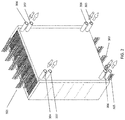
- FIG. 10 shows a three dimensional view of a liquid desiccant mini-split system of FIG. 6 in accordance with one or more embodiments.
- FIG. 11 shows a cut-away view of the system of FIG. 10 in accordance with one or more embodiments.
- FIG. 12 illustrates an exemplary liquid desiccant supply and return structure comprising two bonded plastic tubes creating a heat exchange effect in accordance with one or more embodiments.
- FIG. 1 depicts a new type of liquid desiccant system as described in more detail in U.S. Patent Application Publication No. US 20120125020, which is incorporated by reference herein.
- a conditioner 101 comprises a set of plate structures that are internally hollow.
- a cold heat transfer fluid is generated in cold source 107 and entered into the plates.
- Liquid desiccant solution at 114 is brought onto the outer surface of the plates and runs down the outer surface of each of the plates.
- the liquid desiccant runs behind a thin membrane that is located between the air flow and the surface of the plates.
- Outside air 103 is now blown through the set of wavy plates.
- the liquid desiccant on the surface of the plates attracts the water vapor in the air flow and the cooling water inside the plates helps to inhibit the air temperature from rising.
- the treated air 104 is put into a building space.
- the liquid desiccant is collected at the bottom of the wavy plates at 111 and is transported through a heat exchanger 113 to the top of the regenerator 102 to point 115 where the liquid desiccant is distributed across the wavy plates of the regenerator.
- Return air or optionally outside air 105 is blown across the regenerator plate and water vapor is transported from the liquid desiccant into the leaving air stream 106 .
- An optional heat source 108 provides the driving force for the regeneration.
- the hot transfer fluid 110 from the heat source can be put inside the wavy plates of the regenerator similar to the cold heat transfer fluid on the conditioner.
- the liquid desiccant is collected at the bottom of the wavy plates 102 without the need for either a collection pan or bath so that also on the regenerator the air flow can be horizontal or vertical.
- An optional heat pump 116 can be used to provide cooling and heating of the liquid desiccant. It is also possible to connect a heat pump between the cold source 107 and the hot source 108 , which is thus pumping heat from the cooling fluids rather than the desiccant.
- FIG. 2 describes a 3-way heat exchanger as described in further detail in U.S. patent application Ser. No. 13/915,199 filed on Jun. 11, 2013, Ser. No. 13/915,222 filed on Jun. 11, 2013, and Ser. No. 13/915,262 filed on Jun. 11, 2013, which are all incorporated by reference herein.
- a liquid desiccant enters the structure through ports 304 and is directed behind a series of membranes as described in FIG. 1 .
- the liquid desiccant is collected and removed through ports 305 .
- a cooling or heating fluid is provided through ports 306 and runs counter to the air stream 301 inside the hollow plate structures, again as described in FIG. 1 and in more detail in FIG. 3 .
- the cooling or heating fluids exit through ports 307 .
- the treated air 302 is directed to a space in a building or is exhausted as the case may be.
- FIG. 3 describes a 3-way heat exchanger as described in more detail in U.S. Provisional Patent Applications Ser. No. 61/771,340 filed on Mar. 1, 2013, which is incorporated by reference herein.
- the air stream 251 flows counter to a cooling fluid stream 254 .
- Membranes 252 contain a liquid desiccant 253 that is falling along the wall 255 that contain a heat transfer fluid 254 .
- Water vapor 256 entrained in the air stream is able to transition the membrane 252 and is absorbed into the liquid desiccant 253 .
- the heat of condensation of water 258 that is released during the absorption is conducted through the wall 255 into the heat transfer fluid 254 .
- Sensible heat 257 from the air stream is also conducted through the membrane 252 , liquid desiccant 253 and wall 255 into the heat transfer fluid 254 .
- FIG. 4 illustrates a schematic diagram of a conventional mini-split air conditioning system as is frequently installed on buildings.
- the unit comprises a set of indoor components that generate cool, dehumidified air and a set of outdoor components that release heat to the environment.
- the indoor components comprise a cooling (evaporator) coil 401 through which a fan 407 blows air 408 from the room.
- the cooling coil cools the air and condenses water vapor on the coil which is collected in drain pan 418 and ducted to the outside 419 .
- the resulting cooler, drier air 409 is circulated into the space and provides occupant comfort.
- the cooling coil 401 receives liquid refrigerant at pressures of typically 50-200 psi through line 412 , which has already been expanded to a low temperature and pressure by expansion valve 406 .
- the pressure of the refrigerant in line 412 is typically 300-600 psi.
- the cold liquid refrigerant 410 enters the cooling coil 401 where it picks up heat from the air stream 408 .
- the heat from the air stream evaporates the liquid refrigerant in the coil and the resulting gas is transported through line 404 to the outdoor components and more specifically to the compressor 402 where it is re-compressed to a high pressure of typically 300-600 psi.
- the system can have multiple cooling coils 410 , fans 407 and expansion valves 406 , for example a cooling coil assembly could be located in various rooms that need to be cooled.
- the outdoor components comprise a condenser coil 403 and a condenser fan 417 .
- the fan 417 blows outside air 415 through the condenser coil 403 where it picks up heat from the compressor 402 which is rejected by air stream 416 .
- the compressor 402 creates hot compressed refrigerant in line 411 .
- the heat of compression is rejected in the condenser coil 403 .
- the system can have multiple compressors or multiple condenser coils and fans.
- the primary electrical energy consuming components are the compressor through electrical line 413 , the condenser fan electrical motor through supply line 414 and the evaporator fan motor through line 405 .
- the compressor uses close to 80% of the electricity required to operate the system, with the condenser and evaporator fans taking about 10% of the electricity each.
- FIG. 5A illustrates a schematic representation of a liquid desiccant air conditioner system.
- a 3-way conditioner 503 (which is similar to the conditioner 101 of FIG. 1 ) receives an air stream 501 from a room (“RA”). Fan 502 moves the air 501 through the conditioner 503 wherein the air is cooled and dehumidified. The resulting cool, dry air 504 (“SA”) is supplied to the room for occupant comfort.
- the 3-way conditioner 503 receives a concentrated desiccant 527 in the manner explained under FIGS. 1-3 . It is preferable to use a membrane on the 3-way conditioner 503 to ensure that the desiccant is generally fully contained and is unable to get distributed into the air stream 504 .
- the diluted desiccant 528 which contains the captured water vapor is transported to the outside regenerator 522 . Furthermore the chilled water 509 is provided by pump 508 , enters the conditioner module 503 where it picks up heat from the air as well as latent heat released by the capture of water vapor in the desiccant 527 .
- the warmer water 506 is also brought outside to the heat exchanger 507 on the chiller system 530 . It is worth noting that unlike the mini-split system of FIG. 4 , which has high pressure between 50 and 600 psi, the lines between the indoor and outdoor system of FIG. 5A are all low pressure water and liquid desiccant lines. This allows the lines to be inexpensive plastics rather than refrigerant lines in FIG.
- FIG. 5A which are typically copper and need to be braised in order to withstand the high refrigerant pressures. It is also worth noting that the system of FIG. 5A does not require a condensate drain line like line 419 in FIG. 4 . Rather, any moisture that is condensed into the desiccant is removed as part of the desiccant itself. This also eliminates problems with mold growth in standing water that can occur in the conventional mini-split systems of FIG. 4 .
- the liquid desiccant 528 leaves the conditioner 503 and is moved through the optional heat exchanger 526 to the regenerator 522 by pump 525 . If the desiccant lines 527 and 528 are relatively long they can be thermally connected to each other, which eliminates the need for heat exchanger 526 .
- the chiller system 530 comprises a water to refrigerant evaporator heat exchanger 507 which cools the circulating cooling fluid 506 .
- the liquid, cold refrigerant 517 evaporates in the heat exchanger 507 thereby absorbing the thermal energy from the cooling fluid 506 .
- the gaseous refrigerant 510 is now re-compressed by compressor 511 .
- the compressor 511 ejects hot refrigerant gas 513 , which is liquefied in the condenser heat exchanger 515 .
- the liquid refrigerant 514 then enters expansion valve 516 , where it rapidly cools and exits at a lower pressure.
- the chiller system 530 can be made very compact since the high pressure lines with refrigerant ( 510 , 513 , 514 and 517 ) only have to run very short distances. Furthermore, since the entire refrigerant system is located outside of the space that is to be conditioned, it is possible to utilize refrigerants that normally cannot be used in indoor environments such as by way of example, CO 2 , Ammonia and Propane. These refrigerants are sometimes preferable over the commonly used R410A, R407A, R134A or R1234YF refrigerants, but they are undesirable indoor because of flammability or suffocation or inhaling risks. By keeping all of the refrigerants outside, these risks are essentially eliminated.
- the condenser heat exchanger 515 now releases heat to another cooling fluid loop 519 which brings hot heat transfer fluid 518 to the regenerator 522 .
- Circulating pump 520 brings the heat transfer fluid back to the condenser 515 .
- the 3-way regenerator 522 thus receives a dilute liquid desiccant 528 and hot heat transfer fluid 518 .
- a fan 524 brings outside air 523 (“OA”) through the regenerator 522 .
- the outside air picks up heat and moisture from the heat transfer fluid 518 and desiccant 528 which results in hot humid exhaust air (“EA”) 521 .
- the compressor 511 receives electrical power 512 and typically accounts for 80% of electrical power consumption of the system.
- the fan 502 and fan 524 also receive electrical power 505 and 529 respectively and account for most of the remaining power consumption.
- Pumps 508 , 520 and 525 have relatively low power consumption.
- the compressor 511 will operate more efficiently than the compressor 402 in FIG. 4 for several reasons: the evaporator 507 in FIG. 5A will typically operate at higher temperature than the evaporator 401 in FIG. 4 because the liquid desiccant will condense water at much higher temperature without needing to reach saturation levels in the air stream. Furthermore the condenser 515 in FIG. 5A will operate at lower temperatures than the condenser 403 in FIG. 4 because of the evaporation occurring on the regenerator 522 which effectively keeps the condenser 515 cooler. As a result the system of FIG. 5A will use less electricity than the system of FIG. 4 for similar compressor isentropic efficiencies.
- FIG. 5B shows essentially the same system as FIG. 5A except that the compressor 511 's refrigerant direction has been reversed as indicated by the arrows on refrigerant lines 514 and 510 .
- Reversing the direction of refrigerant flow can be achieved by a 4-way reversing valve (not shown) or other convenient means.
- the desiccant 525 usually has much lower crystallization limit than water vapor.
- the air stream 523 contains water vapor and if the condenser coil 403 gets too cold, this moisture will condense on the surfaces and create ice formation on those surfaces.
- the same moisture in the regenerator of FIG. 5B will condense in the liquid desiccant which—when managed properly will not crystalize until ⁇ 60° C. for some desiccants such as LiCl and water.
- FIG. 6 illustrates an alternate embodiment of a mini-split liquid desiccant system.
- a 3-way liquid desiccant conditioner 503 receives an air stream 501 (“RA”) moved by fan 502 through the conditioner 503 .
- RA air stream 501
- SA supply air stream 504
- Air stream 601 is usually between 0 and 40% of the flow of air stream 504 .
- the dry air stream 601 is now directed through the 3-way indirect evaporative cooling module 602 which is constructed similarly to the 3-way conditioner module 503 , except that instead of using a desiccant behind a membrane, the module now has a water film behind such membrane supplied by water source 607 .
- This water film can be potable water, non-potable water, seawater or waste water or any other convenient water containing substance that is mostly water.
- the water film evaporates in the dry air stream 601 creating a cooling effect in the heat transfer fluid 604 which is then circulated to the conditioner module as cold heat transfer fluid 605 by pump 603 .
- the cold water 605 then cools the conditioner module 503 , which in turn creates cooler drier air 504 , which then results in an even stronger cooling effect in the indirect evaporative module 602 .
- the supply air 504 will ultimately be both dry and cold and is supplied to the space for occupant comfort.
- Conditioner module 503 also receives a concentrated liquid desiccant 527 that absorbs moisture from the air stream 501 . Dilute liquid desiccant 528 is then returned to the regenerator 522 similar to FIG. 5A . It is of course possible to locate the indirect evaporative cooler 602 outside of the space rather than inside, but for thermal reasons it is probably better to mount the indirect evaporator 602 in close proximity to the conditioner 503 .
- the indirect evaporative cooling module 602 does not evaporate all of the water (typically 50 to 80%) and thus a drain 608 is employed.
- the exhaust air stream 606 (“EA1”) from the module evaporative cooling module 602 is brought to the outside since it is warm and very humid.
- the concentrated liquid desiccant 527 and dilute liquid desiccant 528 pass through a heat exchanger 526 by pump 525 .
- the 3-way regenerator 522 as before receives an outdoor air stream 523 through fan 524 .
- a hot heat transfer fluid 518 is applied to the 3-way regenerator module 522 by pump 520 .
- there is no heat from a compressor to use in the regenerator 522 so an external heat source 609 needs to be provided.
- This heat source can be a gas water heater, a solar module, a solar thermal/PV hybrid module (a PVT module), it can be heat from a steam loop or other convenient source of heat or hot water.
- a supplemental heat dump 614 can be employed which can temporarily absorb heat from the heat source 609 .
- An additional fan 613 and air stream 612 are then necessary as well.
- the heat source 609 ensures that the excess water is evaporated from the desiccant 528 so that it can be re-used on the conditioner 503 .
- the exhaust stream 521 (“EA2”) comprises hot, humid air.
- FIG. 7 illustrates the system of FIG. 6 reconfigured slightly to allow for operation in winter heating mode.
- the heat source 609 now provides hot heat transfer fluid to the conditioner module 503 through lines 701 .
- the supply air to the space 504 will be warm and humid.
- This increases the available heating and humidification capacity of the system since both the conditioner 503 and the indirect evaporative “cooler” 602 (or “heater” may be a better moniker) are operating to provide the same hot humid air and this can be handy since heating capacity in winter typically needs to be larger than cooling capacity in summer.
- FIG. 8 shows an embodiment of the system of FIG. 5A .
- the air intake 801 allows for air from space 805 to enter the conditioner unit 503 (not shown).
- the air supply exits from roster 803 into the space.
- a flat screen television 802 or painting, or monitor or any other suitable device can be used to visually hide the conditioner 503 .
- An external wall 804 would be a logical place to mount the conditioner system.
- a regenerator and chiller system 807 can be mounted in a convenient outside location 806 .
- Desiccant supply and return lines 809 and cold heat transfer fluid supply and return lines 808 connect the two sides of the system.
- FIG. 9A shows a cut-away view of the rear side of the system in FIG. 8 .
- the regenerator module 522 receives liquid desiccant from lines 809 .
- a compressor 511 an expansion valve 516 and two refrigerant to liquid heat exchangers 507 and 515 are also shown. Other components have not been shown for convenience.
- FIG. 9B shows a cut-away view of the front side of the system in FIG. 8 .
- the flat screen TV 802 has been omitted to allow a view of the conditioner module 503 .
- FIG. 10 shows an aspect of an embodiment of the system of FIG. 6 .
- the system has an air intake 801 and a supply roster 803 similar to the system of FIG. 8 .
- a TV 802 or something similar can be used to cover the conditioner module 503 .
- the unit can be mounted to wall 804 and provide conditioning of the space 805 .
- the system also has an exhaust 606 that penetrates the wall 804 .
- the regenerator module 902 provides concentrated liquid desiccant to the conditioner section (not shown) through desiccant supply and return lines 809 .
- a water supply line 901 is also shown.
- a source of hot heat transfer fluid can be the solar PVT module 903 which provides hot water through line 905 which after being cooled through the regenerator returns heat transfer fluid to the PVT module 903 through line 904 .
- An integrated hot water storage tank 906 can provide both a hot water buffer as well as a ballast for the PVT module 903 .
- FIG. 11 shows a cut-away view of the system of FIG. 10 .
- the conditioner module 503 can be clearly seen as can the indirect evaporator module 602 .
- Inside the regenerator module 902 one can see the regenerator module 522 as well as the optional heat dump 614 and fan 612 .
- FIG. 12 illustrates a structure 809 for the supply and return of the liquid desiccant to the indoor conditioning unit.
- the structure comprises a polymer material such as for example an extruded High Density Polypropylene or High Density Polyethylene material the comprises two passages 1201 and 1202 for the supply and return of desiccant respectively.
- the wall 1203 between the two passages could be manufactured from a thermally conductive polymer, but in many cases that may not be necessary because the length of the structure 809 is by itself sufficient to provide adequate heat exchange capacity between the supply and return liquids.
Landscapes
- Engineering & Computer Science (AREA)
- Chemical & Material Sciences (AREA)
- Combustion & Propulsion (AREA)
- Mechanical Engineering (AREA)
- General Engineering & Computer Science (AREA)
- Central Air Conditioning (AREA)
- Drying Of Gases (AREA)
- Rigid Pipes And Flexible Pipes (AREA)
- Other Air-Conditioning Systems (AREA)
- Air Humidification (AREA)
Abstract
Description
Claims (20)
Priority Applications (1)
| Application Number | Priority Date | Filing Date | Title |
|---|---|---|---|
| US15/880,275 US10619867B2 (en) | 2013-03-14 | 2018-01-25 | Methods and systems for mini-split liquid desiccant air conditioning |
Applications Claiming Priority (3)
| Application Number | Priority Date | Filing Date | Title |
|---|---|---|---|
| US201361783176P | 2013-03-14 | 2013-03-14 | |
| US14/212,097 US20140260399A1 (en) | 2013-03-14 | 2014-03-14 | Methods and systems for mini-split liquid desiccant air conditioning |
| US15/880,275 US10619867B2 (en) | 2013-03-14 | 2018-01-25 | Methods and systems for mini-split liquid desiccant air conditioning |
Related Parent Applications (1)
| Application Number | Title | Priority Date | Filing Date |
|---|---|---|---|
| US14/212,097 Division US20140260399A1 (en) | 2013-03-14 | 2014-03-14 | Methods and systems for mini-split liquid desiccant air conditioning |
Publications (2)
| Publication Number | Publication Date |
|---|---|
| US20180163977A1 US20180163977A1 (en) | 2018-06-14 |
| US10619867B2 true US10619867B2 (en) | 2020-04-14 |
Family
ID=51521130
Family Applications (2)
| Application Number | Title | Priority Date | Filing Date |
|---|---|---|---|
| US14/212,097 Abandoned US20140260399A1 (en) | 2013-03-14 | 2014-03-14 | Methods and systems for mini-split liquid desiccant air conditioning |
| US15/880,275 Active 2034-07-10 US10619867B2 (en) | 2013-03-14 | 2018-01-25 | Methods and systems for mini-split liquid desiccant air conditioning |
Family Applications Before (1)
| Application Number | Title | Priority Date | Filing Date |
|---|---|---|---|
| US14/212,097 Abandoned US20140260399A1 (en) | 2013-03-14 | 2014-03-14 | Methods and systems for mini-split liquid desiccant air conditioning |
Country Status (8)
| Country | Link |
|---|---|
| US (2) | US20140260399A1 (en) |
| EP (2) | EP2972009B1 (en) |
| JP (2) | JP6568516B2 (en) |
| KR (2) | KR20170133519A (en) |
| CN (1) | CN105121979B (en) |
| ES (1) | ES2761585T3 (en) |
| SA (1) | SA515361072B1 (en) |
| WO (1) | WO2014152905A1 (en) |
Cited By (5)
| Publication number | Priority date | Publication date | Assignee | Title |
|---|---|---|---|---|
| CN112032865A (en) * | 2020-07-30 | 2020-12-04 | 东南大学 | Falling film type liquid humidity regulator and method based on high-voltage electrostatic field polarization effect |
| US10921001B2 (en) | 2017-11-01 | 2021-02-16 | 7Ac Technologies, Inc. | Methods and apparatus for uniform distribution of liquid desiccant in membrane modules in liquid desiccant air-conditioning systems |
| US10941948B2 (en) | 2017-11-01 | 2021-03-09 | 7Ac Technologies, Inc. | Tank system for liquid desiccant air conditioning system |
| US11022330B2 (en) | 2018-05-18 | 2021-06-01 | Emerson Climate Technologies, Inc. | Three-way heat exchangers for liquid desiccant air-conditioning systems and methods of manufacture |
| US11098909B2 (en) | 2012-06-11 | 2021-08-24 | Emerson Climate Technologies, Inc. | Methods and systems for turbulent, corrosion resistant heat exchangers |
Families Citing this family (41)
| Publication number | Priority date | Publication date | Assignee | Title |
|---|---|---|---|---|
| US20120125581A1 (en) | 2010-05-25 | 2012-05-24 | 7Ac Technologies, Inc. | Heat exchanger and associated methods |
| AU2011268661B2 (en) | 2010-06-24 | 2015-11-26 | Nortek Air Solutions Canada, Inc. | Liquid-to-air membrane energy exchanger |
| US8915092B2 (en) | 2011-01-19 | 2014-12-23 | Venmar Ces, Inc. | Heat pump system having a pre-processing module |
| US9810439B2 (en) | 2011-09-02 | 2017-11-07 | Nortek Air Solutions Canada, Inc. | Energy exchange system for conditioning air in an enclosed structure |
| US9816760B2 (en) | 2012-08-24 | 2017-11-14 | Nortek Air Solutions Canada, Inc. | Liquid panel assembly |
| US9506697B2 (en) | 2012-12-04 | 2016-11-29 | 7Ac Technologies, Inc. | Methods and systems for cooling buildings with large heat loads using desiccant chillers |
| KR20200009148A (en) | 2013-03-01 | 2020-01-29 | 7에이씨 테크놀로지스, 아이엔씨. | Desiccant air conditioning methods and systems |
| US9109808B2 (en) | 2013-03-13 | 2015-08-18 | Venmar Ces, Inc. | Variable desiccant control energy exchange system and method |
| US9772124B2 (en) | 2013-03-13 | 2017-09-26 | Nortek Air Solutions Canada, Inc. | Heat pump defrosting system and method |
| WO2014152888A1 (en) | 2013-03-14 | 2014-09-25 | 7 Ac Technologies, Inc. | Methods and systems for liquid desiccant air conditioning system retrofit |
| US10352628B2 (en) | 2013-03-14 | 2019-07-16 | Nortek Air Solutions Canada, Inc. | Membrane-integrated energy exchange assembly |
| WO2014152905A1 (en) | 2013-03-14 | 2014-09-25 | 7Ac Technologies, Inc. | Methods and systems for mini-split liquid desiccant air conditioning |
| US11408681B2 (en) | 2013-03-15 | 2022-08-09 | Nortek Air Solations Canada, Iac. | Evaporative cooling system with liquid-to-air membrane energy exchanger |
| US10584884B2 (en) | 2013-03-15 | 2020-03-10 | Nortek Air Solutions Canada, Inc. | Control system and method for a liquid desiccant air delivery system |
| WO2014201281A1 (en) | 2013-06-12 | 2014-12-18 | 7Ac Technologies, Inc. | In-ceiling liquid desiccant air conditioning system |
| JP6674382B2 (en) * | 2014-03-20 | 2020-04-01 | 7エーシー テクノロジーズ,インコーポレイテッド | Rooftop liquid desiccant system and method |
| AU2015306040A1 (en) | 2014-08-19 | 2017-04-06 | Nortek Air Solutions Canada, Inc. | Liquid to air membrane energy exchangers |
| KR20170086496A (en) | 2014-11-21 | 2017-07-26 | 7에이씨 테크놀로지스, 아이엔씨. | Methods and systems for mini-split liquid desiccant air conditioning |
| WO2016100080A1 (en) | 2014-12-15 | 2016-06-23 | 3M Innovative Properties Company | Heat and mass transfer devices with wettable layers for forming falling films |
| CN107208909B (en) * | 2014-12-15 | 2021-08-10 | 3M创新有限公司 | Heat and mass transfer device with a wettable layer forming a falling film |
| EP3295088B1 (en) | 2015-05-15 | 2022-01-12 | Nortek Air Solutions Canada, Inc. | Using liquid to air membrane energy exchanger for liquid cooling |
| US11092349B2 (en) | 2015-05-15 | 2021-08-17 | Nortek Air Solutions Canada, Inc. | Systems and methods for providing cooling to a heat load |
| EP3314188B1 (en) | 2015-06-26 | 2021-05-12 | Nortek Air Solutions Canada, Inc. | Three-fluid liquid to air membrane energy exchanger |
| CN106642308A (en) * | 2015-11-03 | 2017-05-10 | 青岛海尔空调电子有限公司 | Ultrathin air conditioner indoor unit with independent control over humidity and temperature |
| CN106642421A (en) * | 2015-11-03 | 2017-05-10 | 青岛海尔空调电子有限公司 | Novel multi-split air conditioner dehumidifying system |
| CN106642420A (en) * | 2015-11-03 | 2017-05-10 | 青岛海尔空调电子有限公司 | Novel air conditioner dehumidifying system |
| CN106642442A (en) * | 2015-11-03 | 2017-05-10 | 青岛海尔空调电子有限公司 | Humidity adjustable fresh air air-conditioning system |
| CN109073265B (en) | 2016-03-08 | 2021-09-28 | 北狄空气应对加拿大公司 | System and method for providing cooling to a thermal load |
| CN106016858B (en) * | 2016-05-12 | 2019-06-21 | 上海交通大学 | Conditioner |
| CN106839494B (en) * | 2016-12-26 | 2019-04-19 | 南京航空航天大学 | The double caloic coupling humidification dehumidification vapo(u)rization systems of heat pump and method |
| US11892193B2 (en) | 2017-04-18 | 2024-02-06 | Nortek Air Solutions Canada, Inc. | Desiccant enhanced evaporative cooling systems and methods |
| EP3704414A4 (en) * | 2017-11-01 | 2021-07-28 | 7AC Technologies, Inc. | Methods and systems for liquid desiccant air conditioning |
| WO2020026040A1 (en) * | 2018-07-31 | 2020-02-06 | King Abdullah University Of Science And Technology | Liquid dessicant cooler system and method |
| CN108954527A (en) * | 2018-08-16 | 2018-12-07 | 中山路得斯空调有限公司 | System for small split type liquid dehumidification air conditioner and use method thereof |
| CN113544446B (en) | 2019-03-07 | 2023-07-14 | 艾默生环境优化技术有限公司 | Climate control system with absorption chiller |
| JP2022536647A (en) * | 2019-06-10 | 2022-08-18 | アライアンス フォー サステイナブル エナジー リミテッド ライアビリティ カンパニー | Integrated, desiccant-based cooling and dehumidification |
| US11267675B2 (en) * | 2019-10-04 | 2022-03-08 | Otis Elevator Company | Cooling system for elevator with electronic visual displays |
| WO2022235225A1 (en) * | 2021-05-05 | 2022-11-10 | Enerama Çevre Teknoloji̇leri̇ Sanayi̇ Ve Ti̇caret Anoni̇m Şi̇rketi̇ | The usage of the waste heat in liquid desiccant dehumidification system |
| DE102021114840A1 (en) | 2021-06-09 | 2022-12-15 | Rheinmetall Invent GmbH | HEATING AND COOLING MODULE AND PROCESS |
| GB2594617B (en) * | 2021-06-18 | 2022-04-13 | Gulf Organisation For Res And Development | Air treatment system |
| CN114440356A (en) * | 2022-02-28 | 2022-05-06 | 上海电机学院 | Indirect seawater source heat pump air conditioning system with wind energy auxiliary refrigeration and heating |
Citations (284)
| Publication number | Priority date | Publication date | Assignee | Title |
|---|---|---|---|---|
| US1791086A (en) | 1926-10-11 | 1931-02-03 | Koppers Co Inc | Process for dehydrating gas |
| US2221787A (en) | 1936-08-31 | 1940-11-19 | Calorider Corp | Method and apparatus for conditioning air and other gases |
| US2235322A (en) | 1940-01-29 | 1941-03-18 | J F Pritchard & Company | Air drying |
| US2433741A (en) | 1943-02-13 | 1947-12-30 | Robert B P Crawford | Chemical dehumidifying method and means |
| US2634958A (en) | 1948-12-03 | 1953-04-14 | Modine Mfg Co | Heat exchanger |
| US2660159A (en) | 1950-06-30 | 1953-11-24 | Surface Combustion Corp | Unit heater with draft hood |
| US2708915A (en) | 1952-11-13 | 1955-05-24 | Manville Boiler Co Inc | Crossed duct vertical boiler construction |
| US2939686A (en) | 1955-02-04 | 1960-06-07 | Cherry Burrell Corp | Double port heat exchanger plate |
| US2988171A (en) | 1959-01-29 | 1961-06-13 | Dow Chemical Co | Salt-alkylene glycol dew point depressant |
| US3119446A (en) | 1959-09-17 | 1964-01-28 | American Thermocatalytic Corp | Heat exchangers |
| US3193001A (en) | 1963-02-05 | 1965-07-06 | Lithonia Lighting Inc | Comfort conditioning system |
| US3276634A (en) | 1960-06-24 | 1966-10-04 | Arnot Alfred Erwin Reginald | Water dispensers |
| US3409969A (en) | 1965-06-28 | 1968-11-12 | Westinghouse Electric Corp | Method of explosively welding tubes to tube plates |
| US3410581A (en) | 1967-01-26 | 1968-11-12 | Young Radiator Co | Shell-and-tube type heat-exchanger |
| US3455338A (en) | 1967-06-19 | 1969-07-15 | Walter M Pollit | Composite pipe composition |
| GB1172247A (en) | 1966-04-20 | 1969-11-26 | Apv Co Ltd | Improvements in or relating to Plate Heat Exchangers |
| US3718181A (en) | 1970-08-17 | 1973-02-27 | Du Pont | Plastic heat exchange apparatus |
| US4100331A (en) | 1977-02-03 | 1978-07-11 | Nasa | Dual membrane, hollow fiber fuel cell and method of operating same |
| JPS5477443A (en) | 1977-10-17 | 1979-06-20 | Midland Ross Corp | Air conditioning method and device utilizing solar energy |
| US4176523A (en) | 1978-02-17 | 1979-12-04 | The Garrett Corporation | Adsorption air conditioner |
| US4205529A (en) | 1978-12-04 | 1980-06-03 | The United States Of America As Represented By The United States Department Of Energy | LiCl Dehumidifier LiBr absorption chiller hybrid air conditioning system with energy recovery |
| US4209368A (en) | 1978-08-07 | 1980-06-24 | General Electric Company | Production of halogens by electrolysis of alkali metal halides in a cell having catalytic electrodes bonded to the surface of a porous membrane/separator |
| US4222244A (en) | 1978-11-07 | 1980-09-16 | Gershon Meckler Associates, P.C. | Air conditioning apparatus utilizing solar energy and method |
| US4235221A (en) | 1979-08-23 | 1980-11-25 | Murphy Gerald G | Solar energy system and apparatus |
| US4239507A (en) | 1977-10-06 | 1980-12-16 | Robert Benoit | Method of separation of a gas from a gas mixture |
| US4259849A (en) | 1979-02-15 | 1981-04-07 | Midland-Ross Corporation | Chemical dehumidification system which utilizes a refrigeration unit for supplying energy to the system |
| US4324947A (en) | 1979-05-16 | 1982-04-13 | Dumbeck Robert F | Solar energy collector system |
| US4399862A (en) | 1981-08-17 | 1983-08-23 | Carrier Corporation | Method and apparatus for proven demand air conditioning control |
| US4429545A (en) | 1981-08-03 | 1984-02-07 | Ocean & Atmospheric Science, Inc. | Solar heating system |
| US4435339A (en) | 1979-08-06 | 1984-03-06 | Tower Systems, Inc. | Falling film heat exchanger |
| US4444992A (en) | 1980-11-12 | 1984-04-24 | Massachusetts Institute Of Technology | Photovoltaic-thermal collectors |
| US4583996A (en) | 1983-11-04 | 1986-04-22 | Kabushiki Kaisha Toyota Chuo Kenkyusho | Apparatus for separating condensable gas |
| US4607132A (en) | 1985-08-13 | 1986-08-19 | Jarnagin William S | Integrated PV-thermal panel and process for production |
| US4612019A (en) | 1982-07-22 | 1986-09-16 | The Dow Chemical Company | Method and device for separating water vapor from air |
| US4649899A (en) | 1985-07-24 | 1987-03-17 | Moore Roy A | Solar tracker |
| US4660390A (en) | 1986-03-25 | 1987-04-28 | Worthington Mark N | Air conditioner with three stages of indirect regeneration |
| US4691530A (en) | 1986-09-05 | 1987-09-08 | Milton Meckler | Cogeneration and central regeneration multi-contactor air conditioning system |
| US4703629A (en) | 1986-12-15 | 1987-11-03 | Moore Roy A | Solar cooling apparatus |
| JPS62297647A (en) | 1986-06-18 | 1987-12-24 | Ohbayashigumi Ltd | Dehumidification system of building |
| US4730600A (en) | 1981-12-16 | 1988-03-15 | The Coleman Company, Inc. | Condensing furnace |
| US4744414A (en) | 1986-09-02 | 1988-05-17 | Arco Chemical Company | Plastic film plate-type heat exchanger |
| US4766952A (en) | 1985-11-15 | 1988-08-30 | The Furukawa Electric Co., Ltd. | Waste heat recovery apparatus |
| US4786301A (en) | 1985-07-01 | 1988-11-22 | Rhodes Barry V | Desiccant air conditioning system |
| US4832115A (en) | 1986-07-09 | 1989-05-23 | Albers Technologies Corporation | Method and apparatus for simultaneous heat and mass transfer |
| US4872578A (en) | 1988-06-20 | 1989-10-10 | Itt Standard Of Itt Corporation | Plate type heat exchanger |
| US4882907A (en) | 1980-02-14 | 1989-11-28 | Brown Ii William G | Solar power generation |
| US4887438A (en) | 1989-02-27 | 1989-12-19 | Milton Meckler | Desiccant assisted air conditioner |
| US4900448A (en) | 1988-03-29 | 1990-02-13 | Honeywell Inc. | Membrane dehumidification |
| US4910971A (en) | 1988-02-05 | 1990-03-27 | Hydro Thermal Engineering Pty. Ltd. | Indirect air conditioning system |
| US4939906A (en) | 1989-06-09 | 1990-07-10 | Gas Research Institute | Multi-stage boiler/regenerator for liquid desiccant dehumidifiers |
| US4941324A (en) | 1989-09-12 | 1990-07-17 | Peterson John L | Hybrid vapor-compression/liquid desiccant air conditioner |
| US4955205A (en) | 1989-01-27 | 1990-09-11 | Gas Research Institute | Method of conditioning building air |
| US4971142A (en) | 1989-01-03 | 1990-11-20 | The Air Preheater Company, Inc. | Heat exchanger and heat pipe therefor |
| US4976313A (en) | 1986-10-22 | 1990-12-11 | Alfa-Laval Thermal Ab | Plate heat exchanger with a double-wall structure |
| JPH02306067A (en) | 1989-05-12 | 1990-12-19 | Baltimore Aircoil Co Inc | Absorption type freezing |
| US4979965A (en) | 1988-08-01 | 1990-12-25 | Ahlstromforetagen Svenska Ab | Method of dehumidifying gases |
| US4984434A (en) * | 1989-09-12 | 1991-01-15 | Peterson John L | Hybrid vapor-compression/liquid desiccant air conditioner |
| US4987750A (en) | 1986-07-08 | 1991-01-29 | Gershon Meckler | Air conditioning apparatus |
| US5005371A (en) | 1989-09-04 | 1991-04-09 | Nishiyodo Air Conditioner Co., Ltd. | Adsorption thermal storage apparatus and adsorption thermal storage system including the same |
| JPH03125830A (en) | 1989-10-09 | 1991-05-29 | Daikin Ind Ltd | Humidity adjusting device |
| JPH03213921A (en) | 1990-01-18 | 1991-09-19 | Mitsubishi Electric Corp | Air-conditioner with display screen |
| JPH04273555A (en) | 1991-02-28 | 1992-09-29 | Nec Corp | Commitment system |
| US5181387A (en) | 1985-04-03 | 1993-01-26 | Gershon Meckler | Air conditioning apparatus |
| US5182921A (en) | 1992-04-10 | 1993-02-02 | Industrial Technology Research Institute | Solar dehumidifier |
| US5186903A (en) | 1991-09-27 | 1993-02-16 | North Carolina Center For Scientific Research, Inc. | Apparatus for treating indoor air |
| US5191771A (en) | 1991-07-05 | 1993-03-09 | Milton Meckler | Polymer desiccant and system for dehumidified air conditioning |
| US5221520A (en) | 1991-09-27 | 1993-06-22 | North Carolina Center For Scientific Research, Inc. | Apparatus for treating indoor air |
| US5351497A (en) | 1992-12-17 | 1994-10-04 | Gas Research Institute | Low-flow internally-cooled liquid-desiccant absorber |
| US5361828A (en) | 1993-02-17 | 1994-11-08 | General Electric Company | Scaled heat transfer surface with protruding ramp surface turbulators |
| US5375429A (en) | 1992-06-26 | 1994-12-27 | Sanyo Electric Co., Ltd. | Method and apparatus for controlling an air conditioner with a solor cell |
| US5448895A (en) | 1993-01-08 | 1995-09-12 | Engelhard/Icc | Hybrid heat pump and desiccant space conditioning system and control method |
| US5462113A (en) | 1994-06-20 | 1995-10-31 | Flatplate, Inc. | Three-circuit stacked plate heat exchanger |
| US5471852A (en) | 1991-07-05 | 1995-12-05 | Meckler; Milton | Polymer enhanced glycol desiccant heat-pipe air dehumidifier preconditioning system |
| JPH08105669A (en) | 1994-10-04 | 1996-04-23 | Tokyo Gas Co Ltd | Regenerator for absorption refrigerator |
| US5528905A (en) | 1994-03-25 | 1996-06-25 | Essex Invention S.A. | Contactor, particularly a vapour exchanger for the control of the air hygrometric content, and a device for air handling |
| US5534186A (en) | 1993-12-15 | 1996-07-09 | Gel Sciences, Inc. | Gel-based vapor extractor and methods |
| US5582026A (en) | 1992-07-07 | 1996-12-10 | Barto, Sr.; Stephen W. | Air conditioning system |
| US5595690A (en) | 1995-12-11 | 1997-01-21 | Hamilton Standard | Method for improving water transport and reducing shrinkage stress in membrane humidifying devices and membrane humidifying devices |
| US5605628A (en) | 1988-05-24 | 1997-02-25 | North West Water Group Plc | Composite membranes |
| US5606865A (en) * | 1994-07-06 | 1997-03-04 | Caron; Leofred | Portable air cooler |
| WO1997021061A1 (en) | 1995-12-06 | 1997-06-12 | Indupal B.V. | Continuous-flow heat exchanger, apparatus comprising the same, and evaporator system |
| US5638900A (en) | 1995-01-27 | 1997-06-17 | Ail Research, Inc. | Heat exchange assembly |
| US5641337A (en) | 1995-12-08 | 1997-06-24 | Permea, Inc. | Process for the dehydration of a gas |
| EP0781972A2 (en) | 1995-12-28 | 1997-07-02 | Ebara Corporation | Heat-exchange element |
| US5661983A (en) | 1995-06-02 | 1997-09-02 | Energy International, Inc. | Fluidized bed desiccant cooling system |
| US5685485A (en) | 1994-03-22 | 1997-11-11 | Siemens Aktiengesellschaft | Apparatus for apportioning and atomizing fluids |
| US5685152A (en) | 1995-04-19 | 1997-11-11 | Sterling; Jeffrey S. | Apparatus and method for converting thermal energy to mechanical energy |
| JPH10220914A (en) | 1997-02-07 | 1998-08-21 | Osaka Gas Co Ltd | Plate type evaporator and absorbing device of absorbing type freezer |
| US5797272A (en) | 1994-05-30 | 1998-08-25 | F F Seeley Nominees Pty Ltd | Vacuum dewatering of desiccant brines |
| US5816065A (en) * | 1996-01-12 | 1998-10-06 | Ebara Corporation | Desiccant assisted air conditioning system |
| US5860284A (en) | 1996-07-19 | 1999-01-19 | Novel Aire Technologies, L.L.C. | Thermally regenerated desiccant air conditioner with indirect evaporative cooler |
| US5860285A (en) | 1997-06-06 | 1999-01-19 | Carrier Corporation | System for monitoring outdoor heat exchanger coil |
| WO1999022180A1 (en) | 1997-10-29 | 1999-05-06 | Agam Energy Systems Ltd. | Heat pump/engine system and a method for utilizing same |
| JPH11137948A (en) | 1997-11-07 | 1999-05-25 | Daikin Ind Ltd | Dehumidifier |
| US5928808A (en) | 1995-10-30 | 1999-07-27 | Eshraghi; Ray R. | Fibrous electrochemical feed cells |
| JPH11197439A (en) | 1998-01-14 | 1999-07-27 | Ebara Corp | Dehumidification air-conditioner |
| US5933702A (en) | 1995-09-06 | 1999-08-03 | Universal Air Technology | Photocatalytic air disinfection |
| US5950442A (en) * | 1996-05-24 | 1999-09-14 | Ebara Corporation | Air conditioning system |
| JPH11351700A (en) | 1998-06-08 | 1999-12-24 | Osaka Gas Co Ltd | Plate-type evaporator of absorption refrigerating machine and absorber |
| US6012296A (en) | 1997-08-28 | 2000-01-11 | Honeywell Inc. | Auctioneering temperature and humidity controller with reheat |
| US6018954A (en) | 1995-04-20 | 2000-02-01 | Assaf; Gad | Heat pump system and method for air-conditioning |
| WO2000011426A1 (en) | 1998-08-25 | 2000-03-02 | Agam Energy Systems Ltd. | Evaporative media unit for cooling tower |
| US6035657A (en) | 1995-10-12 | 2000-03-14 | Cryogen, Inc. | Flexible catheter cryosurgical system |
| US6083387A (en) | 1996-06-20 | 2000-07-04 | Burnham Technologies Ltd. | Apparatus for the disinfection of fluids |
| US6103969A (en) | 1999-11-29 | 2000-08-15 | Bussey; Clifford | Solar energy collector |
| JP2000230730A (en) | 1999-02-08 | 2000-08-22 | Daikin Ind Ltd | Air conditioning system |
| WO2000055546A1 (en) | 1999-03-14 | 2000-09-21 | Drykor Ltd. | Dehumidifier/air-conditioning system |
| US6131649A (en) | 1997-09-19 | 2000-10-17 | Millipore Corporation | Heat exchange apparatus |
| US6134903A (en) * | 1997-12-04 | 2000-10-24 | Fedders Corporation | Portable liquid desiccant dehumidifier |
| US6138470A (en) | 1997-12-04 | 2000-10-31 | Fedders Corporation | Portable liquid desiccant dehumidifier |
| US6156102A (en) | 1998-11-10 | 2000-12-05 | Fantom Technologies Inc. | Method and apparatus for recovering water from air |
| US6171374B1 (en) | 1998-05-29 | 2001-01-09 | Ballard Power Systems Inc. | Plate and frame fluid exchanging assembly with unitary plates and seals |
| KR20010017939A (en) | 1999-08-16 | 2001-03-05 | 김병주 | Falling film-type heat and mass exchanger using capillary force |
| US6216489B1 (en) | 1997-12-04 | 2001-04-17 | Fedders Corporation | Liquid desiccant air conditioner |
| US6216483B1 (en) | 1997-12-04 | 2001-04-17 | Fedders Corporation | Liquid desiccant air conditioner |
| US6244062B1 (en) | 1999-11-29 | 2001-06-12 | David Prado | Solar collector system |
| US6247604B1 (en) | 1994-03-17 | 2001-06-19 | Smithkline Beecham P.L.C. | Desiccant-containing stopper |
| US20010008148A1 (en) | 2000-01-13 | 2001-07-19 | Koichi Ito | Air passage switching device and vehicle air conditioner |
| EP1120609A1 (en) | 2000-01-24 | 2001-08-01 | Agam Energy Systems Ltd. | System for dehumidification of air in an enclosure |
| US20010015500A1 (en) | 2000-01-19 | 2001-08-23 | Hiroshi Shimanuki | Humidifer |
| US20020023740A1 (en) | 2000-06-23 | 2002-02-28 | Ail Research, Inc. | Heat exchange assembly |
| US20020026797A1 (en) | 2000-09-05 | 2002-03-07 | Sundhar Shaam P. | Direct current mini air conditioning system |
| US20020038552A1 (en) | 2000-07-27 | 2002-04-04 | Valeriy Maisotsenko | Method and apparatus of indirect-evaporation cooling |
| US6417423B1 (en) | 1998-09-15 | 2002-07-09 | Nanoscale Materials, Inc. | Reactive nanoparticles as destructive adsorbents for biological and chemical contamination |
| US20020098395A1 (en) | 2001-01-22 | 2002-07-25 | Honda Giken Kogyo Kabushiki Kaisha | Fuel cell system and humidification method |
| JP2002206834A (en) | 2000-12-28 | 2002-07-26 | Seibu Giken Co Ltd | Indirect evaporative cooling device |
| US20020104439A1 (en) | 2000-11-13 | 2002-08-08 | Elena N. Komkova | Gas separation device |
| WO2002066901A1 (en) | 2000-05-15 | 2002-08-29 | Drykor Ltd. | Dehumidifier/air-conditioning system |
| US6442951B1 (en) | 1998-06-30 | 2002-09-03 | Ebara Corporation | Heat exchanger, heat pump, dehumidifier, and dehumidifying method |
| US20020139245A1 (en) | 2001-03-30 | 2002-10-03 | Kesten Arthur S. | Dehumidification process and apparatus using collodion membrane |
| US20020139320A1 (en) | 2001-03-30 | 2002-10-03 | Honda Giken Kogyo Kabushiki Kaisha | Humidifying module |
| US20020148602A1 (en) | 2001-04-11 | 2002-10-17 | Toyo Radiator Co., Ltd. | Heat exchanger core |
| WO2002086391A1 (en) | 2001-04-23 | 2002-10-31 | Drykor Ltd. | Apparatus for conditioning air |
| US6488900B1 (en) | 1998-10-20 | 2002-12-03 | Mesosystems Technology, Inc. | Method and apparatus for air purification |
| US6487872B1 (en) | 1997-11-16 | 2002-12-03 | Drykor Ltd. | Dehumidifier system |
| US20030000230A1 (en) | 1999-06-25 | 2003-01-02 | Kopko William L. | High-efficiency air handler |
| WO2003004937A1 (en) | 2001-07-03 | 2003-01-16 | Agam Energy Systems Ltd. | An air conditioning system |
| US6514321B1 (en) | 2000-10-18 | 2003-02-04 | Powermax, Inc. | Dehumidification using desiccants and multiple effect evaporators |
| US20030029185A1 (en) | 2000-04-14 | 2003-02-13 | Kopko William Leslie | Desiccant air conditioner with thermal storage |
| US20030033821A1 (en) | 2001-08-20 | 2003-02-20 | Valeriy Maisotsenko | Method of evaporative cooling of a fluid and apparatus therefor |
| US20030051498A1 (en) | 2001-09-17 | 2003-03-20 | Sanford David I. | Hybrid powered evaporative cooler and method therefor |
| US6539731B2 (en) | 2001-03-30 | 2003-04-01 | Arthus S. Kesten | Dehumidification process and apparatus |
| US6557365B2 (en) | 2001-02-28 | 2003-05-06 | Munters Corporation | Desiccant refrigerant dehumidifier |
| US20030106680A1 (en) | 2001-03-13 | 2003-06-12 | Dais Analytic Corporation | Heat and moisture exchange device |
| US20030121271A1 (en) | 2001-02-28 | 2003-07-03 | Munters Corporation | Desiccant refrigerant dehumidifier systems |
| US6660069B2 (en) | 2001-07-23 | 2003-12-09 | Toyota Jidosha Kabushiki Kaisha | Hydrogen extraction unit |
| US20030230092A1 (en) | 2002-04-24 | 2003-12-18 | Andrew Lowenstein | Air conditioning system |
| US6684649B1 (en) | 1999-11-05 | 2004-02-03 | David A. Thompson | Enthalpy pump |
| US20040040697A1 (en) | 2002-05-03 | 2004-03-04 | Pierre Michel St. | Heat exchanger with nested flange-formed passageway |
| KR20040026242A (en) | 2002-09-23 | 2004-03-31 | 주식회사 에어필 | Liquid dessicant cooling system using heat pump |
| US20040061245A1 (en) | 2002-08-05 | 2004-04-01 | Valeriy Maisotsenko | Indirect evaporative cooling mechanism |
| US6739142B2 (en) | 2000-12-04 | 2004-05-25 | Amos Korin | Membrane desiccation heat pump |
| US20040101698A1 (en) | 1999-09-22 | 2004-05-27 | Nkk Corporation | Resin film laminated metal sheet for can and method for fabricating the same |
| WO2004046618A1 (en) | 2002-11-17 | 2004-06-03 | Agam Energy Systems Ltd. | Air conditioning system and methods_____________________________ |
| US20040109798A1 (en) | 2001-04-25 | 2004-06-10 | Alfa Laval Vicarb | Advanced device for exchange and/or reaction between fluids |
| US20040118125A1 (en) | 2002-12-19 | 2004-06-24 | Potnis Shailesh Vijay | Turbine inlet air-cooling system and method |
| US20040134212A1 (en) | 2003-01-14 | 2004-07-15 | Lg Electronics Inc. | Cooling/heating system of air conditioner |
| US6766817B2 (en) | 2001-07-25 | 2004-07-27 | Tubarc Technologies, Llc | Fluid conduction utilizing a reversible unsaturated siphon with tubarc porosity action |
| US20040194944A1 (en) | 2002-09-17 | 2004-10-07 | Hendricks Terry Joseph | Carbon nanotube heat-exchange systems |
| US20040230092A1 (en) | 2000-09-07 | 2004-11-18 | Thierfelder Christopher A. | Implantable article and method |
| US20040231512A1 (en) | 2003-02-28 | 2004-11-25 | Slayzak Steven J. | Using liquid desiccant as a regenerable filter for capturing and deactivating contaminants |
| US20040261440A1 (en) | 2001-12-27 | 2004-12-30 | Mordechai Forkosh | High efficiency dehumidifiers and combined dehumidifying/air-conditioning systems |
| US6854279B1 (en) | 2003-06-09 | 2005-02-15 | The United States Of America As Represented By The Secretary Of The Navy | Dynamic desiccation cooling system for ships |
| US20050095433A1 (en) | 2003-10-31 | 2005-05-05 | Bogerd Jos V.D. | Multilayered articles and method of manufacture thereof |
| US20050106021A1 (en) | 2003-11-19 | 2005-05-19 | General Electric Company | Hot gas path component with mesh and dimpled cooling |
| US20050109052A1 (en) | 2003-09-30 | 2005-05-26 | Albers Walter F. | Systems and methods for conditioning air and transferring heat and mass between airflows |
| JP2005134060A (en) | 2003-10-31 | 2005-05-26 | Daikin Ind Ltd | Humidity control unit |
| US20050133082A1 (en) | 2003-12-20 | 2005-06-23 | Konold Annemarie H. | Integrated solar energy roofing construction panel |
| KR100510774B1 (en) | 2003-05-26 | 2005-08-30 | 한국생산기술연구원 | Hybrid dehumidified cooling system |
| US6938434B1 (en) | 2002-01-28 | 2005-09-06 | Shields Fair | Cooling system |
| US20050210907A1 (en) | 2004-03-17 | 2005-09-29 | Gillan Leland E | Indirect evaporative cooling of a gas using common product and working gas in a partial counterflow configuration |
| US20050218535A1 (en) | 2002-08-05 | 2005-10-06 | Valeriy Maisotsenko | Indirect evaporative cooling mechanism |
| US20050217485A1 (en) | 2000-04-01 | 2005-10-06 | Membraflow Gmbh & Co. Kg Filter-Systeme | Filter module |
| US20050257551A1 (en) | 2004-05-22 | 2005-11-24 | Gerald Landry | Desiccant-assisted air conditioning system and process |
| US6986428B2 (en) | 2003-05-14 | 2006-01-17 | 3M Innovative Properties Company | Fluid separation membrane module |
| WO2006006177A1 (en) | 2004-07-14 | 2006-01-19 | Agam Energy System Ltd. | Systems and methods for dehumidification |
| US20060070728A1 (en) | 2002-12-02 | 2006-04-06 | Lg Electronics Inc. | Heat exchanger of ventilating system |
| US20060124287A1 (en) | 2002-10-31 | 2006-06-15 | Reinders Johannes Antonius M | Heat exchanger and method of manufacture thereof |
| US20060156750A1 (en) | 2004-04-09 | 2006-07-20 | Andrew Lowenstein | Heat and mass exchanger |
| US20060156761A1 (en) | 2003-07-15 | 2006-07-20 | Stefano Mola | Climate control system with a vapour compression circuit combined with an absorption circuit |
| JP2006263508A (en) | 2005-03-22 | 2006-10-05 | Seiichiro Deguchi | Moisture absorbing device, drying box, air drier and air conditioner |
| US7143597B2 (en) | 2004-06-30 | 2006-12-05 | Speakman Company | Indirect-direct evaporative cooling system operable from sustainable energy source |
| US20060278089A1 (en) | 2003-05-26 | 2006-12-14 | Frank Theilow | Device for extraction of water from atmospheric air |
| JP2006529022A (en) | 2003-05-21 | 2006-12-28 | ヴァイマール,トマス | Thermodynamic apparatus and method for heat absorption |
| US7191821B2 (en) | 2002-09-10 | 2007-03-20 | Alfa Laval Corporate Ab | Plate heat exchanger |
| US7197887B2 (en) | 2000-09-27 | 2007-04-03 | Idalex Technologies, Inc. | Method and plate apparatus for dew point evaporative cooler |
| US20070169916A1 (en) | 2006-01-20 | 2007-07-26 | Wand Steven M | Double-wall, vented heat exchanger |
| US20070175234A1 (en) | 2004-10-12 | 2007-08-02 | Roger Pruitt | Method and apparatus for generating drinking water by condensing air humidity |
| US7279215B2 (en) | 2003-12-03 | 2007-10-09 | 3M Innovative Properties Company | Membrane modules and integrated membrane cassettes |
| JP2008020138A (en) | 2006-07-13 | 2008-01-31 | Daikin Ind Ltd | Humidity adjusting device |
| US7337615B2 (en) | 2003-04-16 | 2008-03-04 | Reidy James J | Thermoelectric, high-efficiency, water generating device |
| WO2008037079A1 (en) | 2006-09-29 | 2008-04-03 | Dpoint Technologies Inc. | Pleated heat and humidity exchanger with flow field elements |
| US20080127965A1 (en) | 2006-12-05 | 2008-06-05 | Andy Burton | Method and apparatus for solar heating air in a forced draft heating system |
| US20080156471A1 (en) | 2006-12-28 | 2008-07-03 | Lg Electronics Inc. | Heat exchange element for ventilating apparatus |
| US20080196758A1 (en) | 2006-12-27 | 2008-08-21 | Mcguire Dennis | Portable, self-sustaining power station |
| US20080203866A1 (en) | 2007-01-26 | 2008-08-28 | Chamberlain Cliff S | Rooftop modular fan coil unit |
| US20080302357A1 (en) | 2007-06-05 | 2008-12-11 | Denault Roger | Solar photovoltaic collector hybrid |
| US20080314567A1 (en) | 2005-12-22 | 2008-12-25 | Alfa Laval Corporate Ab | Heat Exchanger Mixing Systen |
| CN101336358A (en) | 2005-12-22 | 2008-12-31 | 奥克西康比希尔公司 | Evaporative cooling device |
| US20090000732A1 (en) | 2006-01-17 | 2009-01-01 | Henkel Corporation | Bonded Fuel Cell Assembly, Methods, Systems and Sealant Compositions for Producing the Same |
| US20090056919A1 (en) | 2007-08-14 | 2009-03-05 | Prodigy Energy Recovery Systems Inc. | Heat exchanger |
| CN100476308C (en) | 2001-11-26 | 2009-04-08 | 大金工业株式会社 | Humidity controller |
| US20090095162A1 (en) | 2007-10-15 | 2009-04-16 | Green Comfort Systems, Inc. | Dehumidifier system |
| JP2009517622A (en) | 2005-11-28 | 2009-04-30 | オプティマイアー ホールディング ベー フェー イー オー | Dew point cooling system |
| US20090126913A1 (en) | 2007-11-16 | 2009-05-21 | Davis Energy Group, Inc. | Vertical counterflow evaporative cooler |
| US20090173096A1 (en) | 2008-01-08 | 2009-07-09 | Calvin Wade Wohlert | Methodology for converting existing packaged rooftop air conditioning units to be served from a centralized water cooled refrigeration and/or heat pump system |
| US20090183857A1 (en) | 2007-10-19 | 2009-07-23 | David Bland Pierce | Turbulator for a heat exchanger tube, and method of manufacture |
| WO2009094032A1 (en) | 2008-01-25 | 2009-07-30 | Midwest Research Institute | Indirect evaporative cooler using membrane-contained, liquid desiccant for dehumidification |
| JP2009180433A (en) | 2008-01-31 | 2009-08-13 | Tohoku Univ | Wet desiccant air conditioner |
| US20090200022A1 (en) | 2007-10-19 | 2009-08-13 | Jose Luis Bravo | Cryogenic treatment of gas |
| JP2009192101A (en) | 2008-02-12 | 2009-08-27 | Univ Of Tokyo | Displacement air conditioning system |
| US20090238685A1 (en) | 2006-05-08 | 2009-09-24 | Roland Santa Ana | Disguised air displacement device |
| JP2009281668A (en) | 2008-05-22 | 2009-12-03 | Dyna-Air Co Ltd | Humidity controller |
| WO2009144880A1 (en) | 2008-05-27 | 2009-12-03 | ダイナエアー株式会社 | Humidity control device |
| JP2009293831A (en) | 2008-06-03 | 2009-12-17 | Dyna-Air Co Ltd | Humidity conditioning device |
| WO2009157277A1 (en) | 2008-06-22 | 2009-12-30 | 柳町 靖子 | Air conditioning device |
| US20100000247A1 (en) | 2008-07-07 | 2010-01-07 | Bhatti Mohinder S | Solar-assisted climate control system |
| US20100012309A1 (en) | 2006-05-22 | 2010-01-21 | Statiqcooling B.V. | Enthalpy Exchanger |
| CN101636630A (en) | 2006-11-09 | 2010-01-27 | 奥克西康比希尔公司 | High efficiency heat exchanger and dehumidifier |
| US20100018322A1 (en) | 2008-05-07 | 2010-01-28 | Airbus Deutschland Gmbh | Switchable Vortex Generator and Array Formed Therewith, and Uses of the Same |
| US20100051083A1 (en) | 2008-09-03 | 2010-03-04 | Boyk Bill | Solar tracking platform with rotating truss |
| JP2010054136A (en) | 2008-08-28 | 2010-03-11 | Univ Of Tokyo | Dry type desiccant device and air heat source heat pump device |
| US20100077783A1 (en) | 2008-09-30 | 2010-04-01 | Bhatti Mohinder S | Solid oxide fuel cell assisted air conditioning system |
| US20100084120A1 (en) | 2008-10-03 | 2010-04-08 | Jian-Min Yin | Heat exchanger and method of operating the same |
| US20100170776A1 (en) | 2007-01-20 | 2010-07-08 | Ehrenberg Scott G | Multi-phase selective mass transfer through a membrane |
| US7758671B2 (en) | 2006-08-14 | 2010-07-20 | Nanocap Technologies, Llc | Versatile dehumidification process and apparatus |
| JP2010247022A (en) | 2009-04-13 | 2010-11-04 | Mitsubishi Electric Corp | Liquid desiccant regenerating apparatus and desiccant dehumidifying air conditioner |
| EP2256434A2 (en) | 2009-04-08 | 2010-12-01 | Alfonso Di Donato | Heating, air conditioning, air treatment using photovoltaic plants |
| JP2011064359A (en) | 2009-09-15 | 2011-03-31 | Dyna Air Kk | Humidity control device |
| US20110073290A1 (en) | 2009-09-30 | 2011-03-31 | Young Soo Chang | Heat exchanger for dehumidifier using liquid desiccant and dehumidifier using liquid desiccant having the same |
| US7930896B2 (en) | 2003-12-04 | 2011-04-26 | Daikin Industries, Ltd. | Air conditioning system |
| US20110100618A1 (en) | 2009-11-02 | 2011-05-05 | Exaflop, Llc | Data Center With Low Power Usage Effectiveness |
| JP2011092815A (en) | 2009-10-27 | 2011-05-12 | Dyna Air Kk | Dehumidifier |
| WO2011062808A1 (en) | 2009-11-23 | 2011-05-26 | Carrier Corporation | Method and device for air conditioning with humidity control |
| US20110126885A1 (en) | 2008-07-30 | 2011-06-02 | Solaris Synergy Ltd. | Photovoltaic solar power generation system |
| US20110132027A1 (en) | 2008-08-08 | 2011-06-09 | Khaled Gommed | Liquid desiccant dehumidification system and heat /mass exchanger therefor |
| JP2011163682A (en) | 2010-02-10 | 2011-08-25 | Asahi Kogyosha Co Ltd | Indirect evaporation cooling type outdoor air conditioner system |
| WO2011150081A2 (en) | 2010-05-25 | 2011-12-01 | 7Ac Technologies, Inc. | Methods and systems using liquid desiccants for air-conditioning and other processes |
| CN102282426A (en) | 2009-01-30 | 2011-12-14 | 大金工业株式会社 | Drainless air conditioning device |
| WO2011161547A2 (en) | 2010-06-24 | 2011-12-29 | Venmar, Ces Inc. | Liquid-to-air membrane energy exchanger |
| US20120052785A1 (en) | 2010-08-25 | 2012-03-01 | Fujitsu Limited | Cooling system and cooling method |
| US8141379B2 (en) * | 2010-12-02 | 2012-03-27 | King Fahd University Of Petroleum & Minerals | Hybrid solar air-conditioning system |
| JP2012073013A (en) | 2010-02-23 | 2012-04-12 | Chubu Electric Power Co Inc | Heating and cooling device |
| US20120114527A1 (en) | 2009-04-15 | 2012-05-10 | Alfa Laval Corporate Ab | Flow module |
| US20120118155A1 (en) | 2010-11-12 | 2012-05-17 | The Texas A&M Unversity System | Systems and methods for multi-stage air dehumidification and cooling |
| CN202229469U (en) | 2011-08-30 | 2012-05-23 | 福建成信绿集成有限公司 | Compression heat pump system with liquid dehumidifying function |
| WO2012071036A1 (en) | 2010-11-23 | 2012-05-31 | Ducool Ltd. | Air conditioning system |
| WO2012082093A1 (en) | 2010-12-13 | 2012-06-21 | Ducool Ltd. | Method and apparatus for conditioning air |
| US20120152318A1 (en) | 2009-08-28 | 2012-06-21 | Seung Cheol Kee | Water tank having a power-generating function |
| US8337590B2 (en) | 2008-02-08 | 2012-12-25 | R + I Alliance | Device for drying a gas, in particular air, application thereof to a device, and method for collecting a gas sample |
| US20130056177A1 (en) | 2011-09-02 | 2013-03-07 | Venmar Ces, Inc. | Energy exchange system for conditioning air in an enclosed structure |
| JP2013064549A (en) | 2011-09-16 | 2013-04-11 | Daikin Industries Ltd | Air conditioning system |
| US20130101909A1 (en) | 2011-10-24 | 2013-04-25 | Mann+Hummel Gmbh | Humidifier for a Fuel Cell |
| WO2013172789A1 (en) | 2012-05-16 | 2013-11-21 | Nanyang Technological University | A dehumidifying system, a method of dehumidifying and a cooling system |
| US20130340449A1 (en) | 2012-06-20 | 2013-12-26 | Alliance For Sustainable Energy, Llc | Indirect evaporative cooler using membrane-contained liquid desiccant for dehumidification and flocked surfaces to provide coolant flow |
| US8623210B2 (en) | 2006-03-02 | 2014-01-07 | Sei-ichi Manabe | Pore diffusion type flat membrane separating apparatus |
| US8648209B1 (en) | 2005-12-31 | 2014-02-11 | Joseph P. Lastella | Loop reactor for making biodiesel fuel |
| US20140054004A1 (en) | 2012-08-24 | 2014-02-27 | Venmar Ces, Inc. | Membrane support assembly for an energy exchanger |
| US20140054013A1 (en) | 2012-08-24 | 2014-02-27 | Venmar Ces, Inc. | Liquid panel assembly |
| US8695363B2 (en) | 2011-03-24 | 2014-04-15 | General Electric Company | Thermal energy management system and method |
| US20140150481A1 (en) | 2012-12-04 | 2014-06-05 | 7Ac Technologies, Inc. | Methods and systems for cooling buildings with large heat loads using desiccant chillers |
| US20140150662A1 (en) | 2012-06-11 | 2014-06-05 | 7Ac Technologies, Inc. | Methods and systems for turbulent, corrosion resistant heat exchangers |
| US8790454B2 (en) | 2011-04-05 | 2014-07-29 | Korea Institute Of Science And Technology | Heat exchanger having dehumidifying liquid and dehumidifier having the same |
| US20140223947A1 (en) | 2013-02-13 | 2014-08-14 | Carrier Corporation | Dehumidification system for air conditioning |
| US20140245769A1 (en) | 2013-03-01 | 2014-09-04 | 7Ac Technologies, Inc. | Desiccant air conditioning methods and systems |
| US20140250935A1 (en) | 2013-03-11 | 2014-09-11 | General Electric Company | Desiccant based chilling system |
| US20140262144A1 (en) | 2013-03-14 | 2014-09-18 | Venmar Ces, Inc | Membrane-integrated energy exchange assembly |
| US20140260367A1 (en) | 2013-03-15 | 2014-09-18 | Venmar Ces, Inc. | Control system and method for a liquid desiccant air delivery system |
| US20140262125A1 (en) | 2013-03-14 | 2014-09-18 | Venmar Ces, Inc. | Energy exchange assembly with microporous membrane |
| US20140260371A1 (en) | 2013-03-14 | 2014-09-18 | 7Ac Technologies, Inc. | Methods and systems for liquid desiccant air conditioning system retrofit |
| US20140260399A1 (en) | 2013-03-14 | 2014-09-18 | 7Ac Technologies, Inc. | Methods and systems for mini-split liquid desiccant air conditioning |
| US20140264968A1 (en) | 2013-03-15 | 2014-09-18 | Venmar Ces, Inc | System and method for forming an energy exchange assembly |
| US20140260369A1 (en) | 2013-03-15 | 2014-09-18 | Venmar Ces, Inc | Evaporative cooling system with liquid-to-air membrane energy exchanger |
| US20140260398A1 (en) | 2013-03-13 | 2014-09-18 | Alliance For Sustainable Energy, Llc | Indirect evaporative coolers with enhanced heat transfer |
| EP2787293A1 (en) | 2013-03-04 | 2014-10-08 | Carrier Corporation | Integrated membrane dehumidification system |
| US8876943B2 (en) | 2009-09-14 | 2014-11-04 | Random Technologies Llc | Apparatus and methods for changing the concentration of gases in liquids |
| US8881806B2 (en) | 2008-10-13 | 2014-11-11 | Shell Oil Company | Systems and methods for treating a subsurface formation with electrical conductors |
| US20140360373A1 (en) | 2013-06-11 | 2014-12-11 | Hamilton Sundstrand Corporation | Air separation module with removable core |
| WO2014201281A1 (en) | 2013-06-12 | 2014-12-18 | 7Ac Technologies, Inc. | In-ceiling liquid desiccant air conditioning system |
| WO2015077364A1 (en) | 2013-11-19 | 2015-05-28 | 7Ac Technologies, Inc. | Methods and systems for turbulent, corrosion resistant heat exchangers |
| US20150323216A1 (en) | 2012-11-07 | 2015-11-12 | Andri Engineering Ab | A heat exchanger and a ventilation assembly comprising it |
| US20150338140A1 (en) | 2014-03-20 | 2015-11-26 | 7Ac Technologies, Inc. | Rooftop liquid desiccant systems and methods |
| US20160187011A1 (en) | 2014-11-21 | 2016-06-30 | 7Ac Technologies, Inc. | Methods and systems for mini-split liquid desiccant air conditioning |
| US20170106639A1 (en) | 2015-10-20 | 2017-04-20 | 7Ac Technologies, Inc. | Methods and systems for thermoforming two and three way heat exchangers |
-
2014
- 2014-03-14 WO PCT/US2014/028184 patent/WO2014152905A1/en active Application Filing
- 2014-03-14 CN CN201480014508.5A patent/CN105121979B/en active Active
- 2014-03-14 KR KR1020177033994A patent/KR20170133519A/en not_active Application Discontinuation
- 2014-03-14 JP JP2016502726A patent/JP6568516B2/en active Active
- 2014-03-14 EP EP14769878.1A patent/EP2972009B1/en active Active
- 2014-03-14 EP EP19197884.0A patent/EP3614072B1/en active Active
- 2014-03-14 ES ES14769878T patent/ES2761585T3/en active Active
- 2014-03-14 US US14/212,097 patent/US20140260399A1/en not_active Abandoned
- 2014-03-14 KR KR1020157025386A patent/KR102099693B1/en active IP Right Grant
-
2015
- 2015-09-13 SA SA515361072A patent/SA515361072B1/en unknown
-
2018
- 2018-01-25 US US15/880,275 patent/US10619867B2/en active Active
-
2019
- 2019-08-02 JP JP2019143008A patent/JP2019215156A/en active Pending
Patent Citations (386)
| Publication number | Priority date | Publication date | Assignee | Title |
|---|---|---|---|---|
| US1791086A (en) | 1926-10-11 | 1931-02-03 | Koppers Co Inc | Process for dehydrating gas |
| US2221787A (en) | 1936-08-31 | 1940-11-19 | Calorider Corp | Method and apparatus for conditioning air and other gases |
| US2235322A (en) | 1940-01-29 | 1941-03-18 | J F Pritchard & Company | Air drying |
| US2433741A (en) | 1943-02-13 | 1947-12-30 | Robert B P Crawford | Chemical dehumidifying method and means |
| US2634958A (en) | 1948-12-03 | 1953-04-14 | Modine Mfg Co | Heat exchanger |
| US2660159A (en) | 1950-06-30 | 1953-11-24 | Surface Combustion Corp | Unit heater with draft hood |
| US2708915A (en) | 1952-11-13 | 1955-05-24 | Manville Boiler Co Inc | Crossed duct vertical boiler construction |
| US2939686A (en) | 1955-02-04 | 1960-06-07 | Cherry Burrell Corp | Double port heat exchanger plate |
| US2988171A (en) | 1959-01-29 | 1961-06-13 | Dow Chemical Co | Salt-alkylene glycol dew point depressant |
| US3119446A (en) | 1959-09-17 | 1964-01-28 | American Thermocatalytic Corp | Heat exchangers |
| US3276634A (en) | 1960-06-24 | 1966-10-04 | Arnot Alfred Erwin Reginald | Water dispensers |
| US3193001A (en) | 1963-02-05 | 1965-07-06 | Lithonia Lighting Inc | Comfort conditioning system |
| US3409969A (en) | 1965-06-28 | 1968-11-12 | Westinghouse Electric Corp | Method of explosively welding tubes to tube plates |
| GB1172247A (en) | 1966-04-20 | 1969-11-26 | Apv Co Ltd | Improvements in or relating to Plate Heat Exchangers |
| US3410581A (en) | 1967-01-26 | 1968-11-12 | Young Radiator Co | Shell-and-tube type heat-exchanger |
| US3455338A (en) | 1967-06-19 | 1969-07-15 | Walter M Pollit | Composite pipe composition |
| US3718181A (en) | 1970-08-17 | 1973-02-27 | Du Pont | Plastic heat exchange apparatus |
| US4100331A (en) | 1977-02-03 | 1978-07-11 | Nasa | Dual membrane, hollow fiber fuel cell and method of operating same |
| US4239507A (en) | 1977-10-06 | 1980-12-16 | Robert Benoit | Method of separation of a gas from a gas mixture |
| JPS5477443A (en) | 1977-10-17 | 1979-06-20 | Midland Ross Corp | Air conditioning method and device utilizing solar energy |
| US4164125A (en) | 1977-10-17 | 1979-08-14 | Midland-Ross Corporation | Solar energy assisted air-conditioning apparatus and method |
| US4176523A (en) | 1978-02-17 | 1979-12-04 | The Garrett Corporation | Adsorption air conditioner |
| US4209368A (en) | 1978-08-07 | 1980-06-24 | General Electric Company | Production of halogens by electrolysis of alkali metal halides in a cell having catalytic electrodes bonded to the surface of a porous membrane/separator |
| US4222244A (en) | 1978-11-07 | 1980-09-16 | Gershon Meckler Associates, P.C. | Air conditioning apparatus utilizing solar energy and method |
| US4205529A (en) | 1978-12-04 | 1980-06-03 | The United States Of America As Represented By The United States Department Of Energy | LiCl Dehumidifier LiBr absorption chiller hybrid air conditioning system with energy recovery |
| US4259849A (en) | 1979-02-15 | 1981-04-07 | Midland-Ross Corporation | Chemical dehumidification system which utilizes a refrigeration unit for supplying energy to the system |
| US4324947A (en) | 1979-05-16 | 1982-04-13 | Dumbeck Robert F | Solar energy collector system |
| US4435339A (en) | 1979-08-06 | 1984-03-06 | Tower Systems, Inc. | Falling film heat exchanger |
| US4235221A (en) | 1979-08-23 | 1980-11-25 | Murphy Gerald G | Solar energy system and apparatus |
| US4882907A (en) | 1980-02-14 | 1989-11-28 | Brown Ii William G | Solar power generation |
| US4444992A (en) | 1980-11-12 | 1984-04-24 | Massachusetts Institute Of Technology | Photovoltaic-thermal collectors |
| US4429545A (en) | 1981-08-03 | 1984-02-07 | Ocean & Atmospheric Science, Inc. | Solar heating system |
| US4399862A (en) | 1981-08-17 | 1983-08-23 | Carrier Corporation | Method and apparatus for proven demand air conditioning control |
| US4730600A (en) | 1981-12-16 | 1988-03-15 | The Coleman Company, Inc. | Condensing furnace |
| US4612019A (en) | 1982-07-22 | 1986-09-16 | The Dow Chemical Company | Method and device for separating water vapor from air |
| US4583996A (en) | 1983-11-04 | 1986-04-22 | Kabushiki Kaisha Toyota Chuo Kenkyusho | Apparatus for separating condensable gas |
| US5181387A (en) | 1985-04-03 | 1993-01-26 | Gershon Meckler | Air conditioning apparatus |
| US4786301A (en) | 1985-07-01 | 1988-11-22 | Rhodes Barry V | Desiccant air conditioning system |
| US4649899A (en) | 1985-07-24 | 1987-03-17 | Moore Roy A | Solar tracker |
| US4607132A (en) | 1985-08-13 | 1986-08-19 | Jarnagin William S | Integrated PV-thermal panel and process for production |
| US4766952A (en) | 1985-11-15 | 1988-08-30 | The Furukawa Electric Co., Ltd. | Waste heat recovery apparatus |
| US4660390A (en) | 1986-03-25 | 1987-04-28 | Worthington Mark N | Air conditioner with three stages of indirect regeneration |
| JPS62297647A (en) | 1986-06-18 | 1987-12-24 | Ohbayashigumi Ltd | Dehumidification system of building |
| US4987750A (en) | 1986-07-08 | 1991-01-29 | Gershon Meckler | Air conditioning apparatus |
| US4832115A (en) | 1986-07-09 | 1989-05-23 | Albers Technologies Corporation | Method and apparatus for simultaneous heat and mass transfer |
| US4744414A (en) | 1986-09-02 | 1988-05-17 | Arco Chemical Company | Plastic film plate-type heat exchanger |
| US4691530A (en) | 1986-09-05 | 1987-09-08 | Milton Meckler | Cogeneration and central regeneration multi-contactor air conditioning system |
| US4976313A (en) | 1986-10-22 | 1990-12-11 | Alfa-Laval Thermal Ab | Plate heat exchanger with a double-wall structure |
| US4703629A (en) | 1986-12-15 | 1987-11-03 | Moore Roy A | Solar cooling apparatus |
| US4910971A (en) | 1988-02-05 | 1990-03-27 | Hydro Thermal Engineering Pty. Ltd. | Indirect air conditioning system |
| US4900448A (en) | 1988-03-29 | 1990-02-13 | Honeywell Inc. | Membrane dehumidification |
| US5605628A (en) | 1988-05-24 | 1997-02-25 | North West Water Group Plc | Composite membranes |
| US4872578A (en) | 1988-06-20 | 1989-10-10 | Itt Standard Of Itt Corporation | Plate type heat exchanger |
| US4979965A (en) | 1988-08-01 | 1990-12-25 | Ahlstromforetagen Svenska Ab | Method of dehumidifying gases |
| US4971142A (en) | 1989-01-03 | 1990-11-20 | The Air Preheater Company, Inc. | Heat exchanger and heat pipe therefor |
| US4955205A (en) | 1989-01-27 | 1990-09-11 | Gas Research Institute | Method of conditioning building air |
| US4887438A (en) | 1989-02-27 | 1989-12-19 | Milton Meckler | Desiccant assisted air conditioner |
| JPH02306067A (en) | 1989-05-12 | 1990-12-19 | Baltimore Aircoil Co Inc | Absorption type freezing |
| US4939906A (en) | 1989-06-09 | 1990-07-10 | Gas Research Institute | Multi-stage boiler/regenerator for liquid desiccant dehumidifiers |
| US5005371A (en) | 1989-09-04 | 1991-04-09 | Nishiyodo Air Conditioner Co., Ltd. | Adsorption thermal storage apparatus and adsorption thermal storage system including the same |
| US4984434A (en) * | 1989-09-12 | 1991-01-15 | Peterson John L | Hybrid vapor-compression/liquid desiccant air conditioner |
| US4941324A (en) | 1989-09-12 | 1990-07-17 | Peterson John L | Hybrid vapor-compression/liquid desiccant air conditioner |
| JPH03125830A (en) | 1989-10-09 | 1991-05-29 | Daikin Ind Ltd | Humidity adjusting device |
| JPH03213921A (en) | 1990-01-18 | 1991-09-19 | Mitsubishi Electric Corp | Air-conditioner with display screen |
| JPH04273555A (en) | 1991-02-28 | 1992-09-29 | Nec Corp | Commitment system |
| US5471852A (en) | 1991-07-05 | 1995-12-05 | Meckler; Milton | Polymer enhanced glycol desiccant heat-pipe air dehumidifier preconditioning system |
| US5191771A (en) | 1991-07-05 | 1993-03-09 | Milton Meckler | Polymer desiccant and system for dehumidified air conditioning |
| US5221520A (en) | 1991-09-27 | 1993-06-22 | North Carolina Center For Scientific Research, Inc. | Apparatus for treating indoor air |
| US5186903A (en) | 1991-09-27 | 1993-02-16 | North Carolina Center For Scientific Research, Inc. | Apparatus for treating indoor air |
| US5182921A (en) | 1992-04-10 | 1993-02-02 | Industrial Technology Research Institute | Solar dehumidifier |
| US5375429A (en) | 1992-06-26 | 1994-12-27 | Sanyo Electric Co., Ltd. | Method and apparatus for controlling an air conditioner with a solor cell |
| US5582026A (en) | 1992-07-07 | 1996-12-10 | Barto, Sr.; Stephen W. | Air conditioning system |
| US5351497A (en) | 1992-12-17 | 1994-10-04 | Gas Research Institute | Low-flow internally-cooled liquid-desiccant absorber |
| US5448895A (en) | 1993-01-08 | 1995-09-12 | Engelhard/Icc | Hybrid heat pump and desiccant space conditioning system and control method |
| US5361828A (en) | 1993-02-17 | 1994-11-08 | General Electric Company | Scaled heat transfer surface with protruding ramp surface turbulators |
| US5534186A (en) | 1993-12-15 | 1996-07-09 | Gel Sciences, Inc. | Gel-based vapor extractor and methods |
| US6247604B1 (en) | 1994-03-17 | 2001-06-19 | Smithkline Beecham P.L.C. | Desiccant-containing stopper |
| US5685485A (en) | 1994-03-22 | 1997-11-11 | Siemens Aktiengesellschaft | Apparatus for apportioning and atomizing fluids |
| US5528905A (en) | 1994-03-25 | 1996-06-25 | Essex Invention S.A. | Contactor, particularly a vapour exchanger for the control of the air hygrometric content, and a device for air handling |
| US5797272A (en) | 1994-05-30 | 1998-08-25 | F F Seeley Nominees Pty Ltd | Vacuum dewatering of desiccant brines |
| US5462113A (en) | 1994-06-20 | 1995-10-31 | Flatplate, Inc. | Three-circuit stacked plate heat exchanger |
| US5606865A (en) * | 1994-07-06 | 1997-03-04 | Caron; Leofred | Portable air cooler |
| JPH08105669A (en) | 1994-10-04 | 1996-04-23 | Tokyo Gas Co Ltd | Regenerator for absorption refrigerator |
| US5638900A (en) | 1995-01-27 | 1997-06-17 | Ail Research, Inc. | Heat exchange assembly |
| US5685152A (en) | 1995-04-19 | 1997-11-11 | Sterling; Jeffrey S. | Apparatus and method for converting thermal energy to mechanical energy |
| US6018954A (en) | 1995-04-20 | 2000-02-01 | Assaf; Gad | Heat pump system and method for air-conditioning |
| USRE39288E1 (en) | 1995-04-20 | 2006-09-19 | Gad Assaf | Heat pump system and method for air-conditioning |
| US5661983A (en) | 1995-06-02 | 1997-09-02 | Energy International, Inc. | Fluidized bed desiccant cooling system |
| US5933702A (en) | 1995-09-06 | 1999-08-03 | Universal Air Technology | Photocatalytic air disinfection |
| US6035657A (en) | 1995-10-12 | 2000-03-14 | Cryogen, Inc. | Flexible catheter cryosurgical system |
| US5928808A (en) | 1995-10-30 | 1999-07-27 | Eshraghi; Ray R. | Fibrous electrochemical feed cells |
| WO1997021061A1 (en) | 1995-12-06 | 1997-06-12 | Indupal B.V. | Continuous-flow heat exchanger, apparatus comprising the same, and evaporator system |
| US5641337A (en) | 1995-12-08 | 1997-06-24 | Permea, Inc. | Process for the dehydration of a gas |
| US5595690A (en) | 1995-12-11 | 1997-01-21 | Hamilton Standard | Method for improving water transport and reducing shrinkage stress in membrane humidifying devices and membrane humidifying devices |
| US5832993A (en) | 1995-12-28 | 1998-11-10 | Ebara Corporation | Heat-exchange element |
| EP0781972A2 (en) | 1995-12-28 | 1997-07-02 | Ebara Corporation | Heat-exchange element |
| JPH09184692A (en) | 1995-12-28 | 1997-07-15 | Ebara Corp | Heat exchanging element |
| US5816065A (en) * | 1996-01-12 | 1998-10-06 | Ebara Corporation | Desiccant assisted air conditioning system |
| US5950442A (en) * | 1996-05-24 | 1999-09-14 | Ebara Corporation | Air conditioning system |
| US6083387A (en) | 1996-06-20 | 2000-07-04 | Burnham Technologies Ltd. | Apparatus for the disinfection of fluids |
| US5860284A (en) | 1996-07-19 | 1999-01-19 | Novel Aire Technologies, L.L.C. | Thermally regenerated desiccant air conditioner with indirect evaporative cooler |
| JPH10220914A (en) | 1997-02-07 | 1998-08-21 | Osaka Gas Co Ltd | Plate type evaporator and absorbing device of absorbing type freezer |
| US5860285A (en) | 1997-06-06 | 1999-01-19 | Carrier Corporation | System for monitoring outdoor heat exchanger coil |
| US6012296A (en) | 1997-08-28 | 2000-01-11 | Honeywell Inc. | Auctioneering temperature and humidity controller with reheat |
| JP2001517773A (en) | 1997-09-19 | 2001-10-09 | ミリポア・コーポレイション | Heat exchange equipment |
| US6131649A (en) | 1997-09-19 | 2000-10-17 | Millipore Corporation | Heat exchange apparatus |
| WO1999022180A1 (en) | 1997-10-29 | 1999-05-06 | Agam Energy Systems Ltd. | Heat pump/engine system and a method for utilizing same |
| US6266975B1 (en) | 1997-10-29 | 2001-07-31 | Agam Energy Systems Ltd. | Heat pump/engine system and a method for utilizing same |
| JPH11137948A (en) | 1997-11-07 | 1999-05-25 | Daikin Ind Ltd | Dehumidifier |
| US6487872B1 (en) | 1997-11-16 | 2002-12-03 | Drykor Ltd. | Dehumidifier system |
| US6546746B2 (en) | 1997-11-16 | 2003-04-15 | Drykor Ltd. | Dehumidifier system |
| US20040112077A1 (en) * | 1997-11-16 | 2004-06-17 | Mordechai Forkosh | Dehumidifier/air-conditioning system |
| US6976365B2 (en) * | 1997-11-16 | 2005-12-20 | Drykor Ltd. | Dehumidifier/air-conditioning system |
| US6138470A (en) | 1997-12-04 | 2000-10-31 | Fedders Corporation | Portable liquid desiccant dehumidifier |
| US6216489B1 (en) | 1997-12-04 | 2001-04-17 | Fedders Corporation | Liquid desiccant air conditioner |
| US6216483B1 (en) | 1997-12-04 | 2001-04-17 | Fedders Corporation | Liquid desiccant air conditioner |
| US6134903A (en) * | 1997-12-04 | 2000-10-24 | Fedders Corporation | Portable liquid desiccant dehumidifier |
| US20010013226A1 (en) * | 1997-12-04 | 2001-08-16 | Potnis Shailesh V. | Liquid desiccant air conditioner |
| JPH11197439A (en) | 1998-01-14 | 1999-07-27 | Ebara Corp | Dehumidification air-conditioner |
| US6171374B1 (en) | 1998-05-29 | 2001-01-09 | Ballard Power Systems Inc. | Plate and frame fluid exchanging assembly with unitary plates and seals |
| JPH11351700A (en) | 1998-06-08 | 1999-12-24 | Osaka Gas Co Ltd | Plate-type evaporator of absorption refrigerating machine and absorber |
| US6442951B1 (en) | 1998-06-30 | 2002-09-03 | Ebara Corporation | Heat exchanger, heat pump, dehumidifier, and dehumidifying method |
| WO2000011426A1 (en) | 1998-08-25 | 2000-03-02 | Agam Energy Systems Ltd. | Evaporative media unit for cooling tower |
| US6502807B1 (en) | 1998-08-25 | 2003-01-07 | Agam Energy Systems Ltd. | Evaporative media unit for cooling tower |
| US6417423B1 (en) | 1998-09-15 | 2002-07-09 | Nanoscale Materials, Inc. | Reactive nanoparticles as destructive adsorbents for biological and chemical contamination |
| US6488900B1 (en) | 1998-10-20 | 2002-12-03 | Mesosystems Technology, Inc. | Method and apparatus for air purification |
| US6156102A (en) | 1998-11-10 | 2000-12-05 | Fantom Technologies Inc. | Method and apparatus for recovering water from air |
| JP2000230730A (en) | 1999-02-08 | 2000-08-22 | Daikin Ind Ltd | Air conditioning system |
| JP4273555B2 (en) | 1999-02-08 | 2009-06-03 | ダイキン工業株式会社 | Air conditioning system |
| WO2000055546A1 (en) | 1999-03-14 | 2000-09-21 | Drykor Ltd. | Dehumidifier/air-conditioning system |
| US20030000230A1 (en) | 1999-06-25 | 2003-01-02 | Kopko William L. | High-efficiency air handler |
| KR20010017939A (en) | 1999-08-16 | 2001-03-05 | 김병주 | Falling film-type heat and mass exchanger using capillary force |
| US20040101698A1 (en) | 1999-09-22 | 2004-05-27 | Nkk Corporation | Resin film laminated metal sheet for can and method for fabricating the same |
| US6684649B1 (en) | 1999-11-05 | 2004-02-03 | David A. Thompson | Enthalpy pump |
| US6244062B1 (en) | 1999-11-29 | 2001-06-12 | David Prado | Solar collector system |
| US6103969A (en) | 1999-11-29 | 2000-08-15 | Bussey; Clifford | Solar energy collector |
| US20010008148A1 (en) | 2000-01-13 | 2001-07-19 | Koichi Ito | Air passage switching device and vehicle air conditioner |
| US20010015500A1 (en) | 2000-01-19 | 2001-08-23 | Hiroshi Shimanuki | Humidifer |
| US6463750B2 (en) | 2000-01-24 | 2002-10-15 | Agam Energy Systems Ltd. | System for dehumidification of air in an enclosure |
| EP1120609A1 (en) | 2000-01-24 | 2001-08-01 | Agam Energy Systems Ltd. | System for dehumidification of air in an enclosure |
| US20050217485A1 (en) | 2000-04-01 | 2005-10-06 | Membraflow Gmbh & Co. Kg Filter-Systeme | Filter module |
| US20030029185A1 (en) | 2000-04-14 | 2003-02-13 | Kopko William Leslie | Desiccant air conditioner with thermal storage |
| WO2002066901A1 (en) | 2000-05-15 | 2002-08-29 | Drykor Ltd. | Dehumidifier/air-conditioning system |
| US6745826B2 (en) | 2000-06-23 | 2004-06-08 | Ail Research, Inc. | Heat exchange assembly |
| US20020023740A1 (en) | 2000-06-23 | 2002-02-28 | Ail Research, Inc. | Heat exchange assembly |
| US6497107B2 (en) | 2000-07-27 | 2002-12-24 | Idalex Technologies, Inc. | Method and apparatus of indirect-evaporation cooling |
| US20020038552A1 (en) | 2000-07-27 | 2002-04-04 | Valeriy Maisotsenko | Method and apparatus of indirect-evaporation cooling |
| US20020026797A1 (en) | 2000-09-05 | 2002-03-07 | Sundhar Shaam P. | Direct current mini air conditioning system |
| US20040230092A1 (en) | 2000-09-07 | 2004-11-18 | Thierfelder Christopher A. | Implantable article and method |
| US7197887B2 (en) | 2000-09-27 | 2007-04-03 | Idalex Technologies, Inc. | Method and plate apparatus for dew point evaporative cooler |
| US6514321B1 (en) | 2000-10-18 | 2003-02-04 | Powermax, Inc. | Dehumidification using desiccants and multiple effect evaporators |
| US20020104439A1 (en) | 2000-11-13 | 2002-08-08 | Elena N. Komkova | Gas separation device |
| US6739142B2 (en) | 2000-12-04 | 2004-05-25 | Amos Korin | Membrane desiccation heat pump |
| JP2002206834A (en) | 2000-12-28 | 2002-07-26 | Seibu Giken Co Ltd | Indirect evaporative cooling device |
| US20020098395A1 (en) | 2001-01-22 | 2002-07-25 | Honda Giken Kogyo Kabushiki Kaisha | Fuel cell system and humidification method |
| CN100366981C (en) | 2001-02-21 | 2008-02-06 | 德瑞艾克有限公司 | Dehumidifier/air-conditioning system |
| US20030121271A1 (en) | 2001-02-28 | 2003-07-03 | Munters Corporation | Desiccant refrigerant dehumidifier systems |
| US6557365B2 (en) | 2001-02-28 | 2003-05-06 | Munters Corporation | Desiccant refrigerant dehumidifier |
| US20030106680A1 (en) | 2001-03-13 | 2003-06-12 | Dais Analytic Corporation | Heat and moisture exchange device |
| US20020139245A1 (en) | 2001-03-30 | 2002-10-03 | Kesten Arthur S. | Dehumidification process and apparatus using collodion membrane |
| US6497749B2 (en) | 2001-03-30 | 2002-12-24 | United Technologies Corporation | Dehumidification process and apparatus using collodion membrane |
| US6539731B2 (en) | 2001-03-30 | 2003-04-01 | Arthus S. Kesten | Dehumidification process and apparatus |
| US20020139320A1 (en) | 2001-03-30 | 2002-10-03 | Honda Giken Kogyo Kabushiki Kaisha | Humidifying module |
| US20020148602A1 (en) | 2001-04-11 | 2002-10-17 | Toyo Radiator Co., Ltd. | Heat exchanger core |
| JP2004524504A (en) | 2001-04-23 | 2004-08-12 | ドライコー リミテッド | Air conditioner |
| WO2002086391A1 (en) | 2001-04-23 | 2002-10-31 | Drykor Ltd. | Apparatus for conditioning air |
| US20040211207A1 (en) | 2001-04-23 | 2004-10-28 | Mordechai Forkosh | Apparatus for conditioning air |
| US20040109798A1 (en) | 2001-04-25 | 2004-06-10 | Alfa Laval Vicarb | Advanced device for exchange and/or reaction between fluids |
| WO2003004937A1 (en) | 2001-07-03 | 2003-01-16 | Agam Energy Systems Ltd. | An air conditioning system |
| US20040168462A1 (en) | 2001-07-03 | 2004-09-02 | Gad Assaf | Air conditioning system |
| US6660069B2 (en) | 2001-07-23 | 2003-12-09 | Toyota Jidosha Kabushiki Kaisha | Hydrogen extraction unit |
| US7066586B2 (en) | 2001-07-25 | 2006-06-27 | Tubarc Technologies, Llc | Ink refill and recharging system |
| US6766817B2 (en) | 2001-07-25 | 2004-07-27 | Tubarc Technologies, Llc | Fluid conduction utilizing a reversible unsaturated siphon with tubarc porosity action |
| US6918404B2 (en) | 2001-07-25 | 2005-07-19 | Tubarc Technologies, Llc | Irrigation and drainage based on hydrodynamic unsaturated fluid flow |
| US20030033821A1 (en) | 2001-08-20 | 2003-02-20 | Valeriy Maisotsenko | Method of evaporative cooling of a fluid and apparatus therefor |
| US6854278B2 (en) | 2001-08-20 | 2005-02-15 | Valeriy Maisotsenko | Method of evaporative cooling of a fluid and apparatus therefor |
| US20030051498A1 (en) | 2001-09-17 | 2003-03-20 | Sanford David I. | Hybrid powered evaporative cooler and method therefor |
| CN100476308C (en) | 2001-11-26 | 2009-04-08 | 大金工业株式会社 | Humidity controller |
| US20040261440A1 (en) | 2001-12-27 | 2004-12-30 | Mordechai Forkosh | High efficiency dehumidifiers and combined dehumidifying/air-conditioning systems |
| US6938434B1 (en) | 2002-01-28 | 2005-09-06 | Shields Fair | Cooling system |
| US6848265B2 (en) | 2002-04-24 | 2005-02-01 | Ail Research, Inc. | Air conditioning system |
| US20030230092A1 (en) | 2002-04-24 | 2003-12-18 | Andrew Lowenstein | Air conditioning system |
| US20040040697A1 (en) | 2002-05-03 | 2004-03-04 | Pierre Michel St. | Heat exchanger with nested flange-formed passageway |
| US20050218535A1 (en) | 2002-08-05 | 2005-10-06 | Valeriy Maisotsenko | Indirect evaporative cooling mechanism |
| US20040061245A1 (en) | 2002-08-05 | 2004-04-01 | Valeriy Maisotsenko | Indirect evaporative cooling mechanism |
| US7191821B2 (en) | 2002-09-10 | 2007-03-20 | Alfa Laval Corporate Ab | Plate heat exchanger |
| US20040194944A1 (en) | 2002-09-17 | 2004-10-07 | Hendricks Terry Joseph | Carbon nanotube heat-exchange systems |
| KR20040026242A (en) | 2002-09-23 | 2004-03-31 | 주식회사 에어필 | Liquid dessicant cooling system using heat pump |
| US20060124287A1 (en) | 2002-10-31 | 2006-06-15 | Reinders Johannes Antonius M | Heat exchanger and method of manufacture thereof |
| US7430878B2 (en) | 2002-11-17 | 2008-10-07 | Agam Energy Systems, Ltd. | Air conditioning system and methods |
| WO2004046618A1 (en) | 2002-11-17 | 2004-06-03 | Agam Energy Systems Ltd. | Air conditioning system and methods_____________________________ |
| US20060042295A1 (en) | 2002-11-17 | 2006-03-02 | Gad Assaf | Air conditioning system and methods |
| EP1563229A1 (en) | 2002-11-17 | 2005-08-17 | Agam Energy Systems Ltd. | Air conditioning system and methods |
| US7228891B2 (en) | 2002-12-02 | 2007-06-12 | Lg Electronics Inc. | Heat exchanger of ventilating system |
| US20060070728A1 (en) | 2002-12-02 | 2006-04-06 | Lg Electronics Inc. | Heat exchanger of ventilating system |
| US20040118125A1 (en) | 2002-12-19 | 2004-06-24 | Potnis Shailesh Vijay | Turbine inlet air-cooling system and method |
| US6945065B2 (en) | 2003-01-14 | 2005-09-20 | Lg Electronics Inc. | Cooling/heating system of air conditioner |
| US20040134212A1 (en) | 2003-01-14 | 2004-07-15 | Lg Electronics Inc. | Cooling/heating system of air conditioner |
| US7306650B2 (en) | 2003-02-28 | 2007-12-11 | Midwest Research Institute | Using liquid desiccant as a regenerable filter for capturing and deactivating contaminants |
| US20040231512A1 (en) | 2003-02-28 | 2004-11-25 | Slayzak Steven J. | Using liquid desiccant as a regenerable filter for capturing and deactivating contaminants |
| US7337615B2 (en) | 2003-04-16 | 2008-03-04 | Reidy James J | Thermoelectric, high-efficiency, water generating device |
| US6986428B2 (en) | 2003-05-14 | 2006-01-17 | 3M Innovative Properties Company | Fluid separation membrane module |
| JP2006529022A (en) | 2003-05-21 | 2006-12-28 | ヴァイマール,トマス | Thermodynamic apparatus and method for heat absorption |
| KR100510774B1 (en) | 2003-05-26 | 2005-08-30 | 한국생산기술연구원 | Hybrid dehumidified cooling system |
| US20060278089A1 (en) | 2003-05-26 | 2006-12-14 | Frank Theilow | Device for extraction of water from atmospheric air |
| US6854279B1 (en) | 2003-06-09 | 2005-02-15 | The United States Of America As Represented By The Secretary Of The Navy | Dynamic desiccation cooling system for ships |
| US20060156761A1 (en) | 2003-07-15 | 2006-07-20 | Stefano Mola | Climate control system with a vapour compression circuit combined with an absorption circuit |
| US20050109052A1 (en) | 2003-09-30 | 2005-05-26 | Albers Walter F. | Systems and methods for conditioning air and transferring heat and mass between airflows |
| JP2005134060A (en) | 2003-10-31 | 2005-05-26 | Daikin Ind Ltd | Humidity control unit |
| US20050095433A1 (en) | 2003-10-31 | 2005-05-05 | Bogerd Jos V.D. | Multilayered articles and method of manufacture thereof |
| US7258923B2 (en) | 2003-10-31 | 2007-08-21 | General Electric Company | Multilayered articles and method of manufacture thereof |
| US20050106021A1 (en) | 2003-11-19 | 2005-05-19 | General Electric Company | Hot gas path component with mesh and dimpled cooling |
| US7279215B2 (en) | 2003-12-03 | 2007-10-09 | 3M Innovative Properties Company | Membrane modules and integrated membrane cassettes |
| US7930896B2 (en) | 2003-12-04 | 2011-04-26 | Daikin Industries, Ltd. | Air conditioning system |
| US20050133082A1 (en) | 2003-12-20 | 2005-06-23 | Konold Annemarie H. | Integrated solar energy roofing construction panel |
| US20050210907A1 (en) | 2004-03-17 | 2005-09-29 | Gillan Leland E | Indirect evaporative cooling of a gas using common product and working gas in a partial counterflow configuration |
| US20060156750A1 (en) | 2004-04-09 | 2006-07-20 | Andrew Lowenstein | Heat and mass exchanger |
| US7269966B2 (en) | 2004-04-09 | 2007-09-18 | Ail Reasearch, Inc. | Heat and mass exchanger |
| US20050257551A1 (en) | 2004-05-22 | 2005-11-24 | Gerald Landry | Desiccant-assisted air conditioning system and process |
| US7143597B2 (en) | 2004-06-30 | 2006-12-05 | Speakman Company | Indirect-direct evaporative cooling system operable from sustainable energy source |
| US7938888B2 (en) | 2004-07-14 | 2011-05-10 | Agam Energy Systems Ltd. | Systems and methods for dehumidification |
| US20070234743A1 (en) | 2004-07-14 | 2007-10-11 | Agam Energy System Ltd. | Systems and Methods for Dehumidification |
| WO2006006177A1 (en) | 2004-07-14 | 2006-01-19 | Agam Energy System Ltd. | Systems and methods for dehumidification |
| EP1781995A1 (en) | 2004-07-14 | 2007-05-09 | Agam Energy Systems Ltd. | Systems and methods for dehumidification |
| US20070175234A1 (en) | 2004-10-12 | 2007-08-02 | Roger Pruitt | Method and apparatus for generating drinking water by condensing air humidity |
| JP2006263508A (en) | 2005-03-22 | 2006-10-05 | Seiichiro Deguchi | Moisture absorbing device, drying box, air drier and air conditioner |
| JP2009517622A (en) | 2005-11-28 | 2009-04-30 | オプティマイアー ホールディング ベー フェー イー オー | Dew point cooling system |
| US8499576B2 (en) | 2005-11-28 | 2013-08-06 | Optimair Bv Io | Dewpoint cooling device |
| US20080314567A1 (en) | 2005-12-22 | 2008-12-25 | Alfa Laval Corporate Ab | Heat Exchanger Mixing Systen |
| CN101336358A (en) | 2005-12-22 | 2008-12-31 | 奥克西康比希尔公司 | Evaporative cooling device |
| US8648209B1 (en) | 2005-12-31 | 2014-02-11 | Joseph P. Lastella | Loop reactor for making biodiesel fuel |
| US20090000732A1 (en) | 2006-01-17 | 2009-01-01 | Henkel Corporation | Bonded Fuel Cell Assembly, Methods, Systems and Sealant Compositions for Producing the Same |
| US20070169916A1 (en) | 2006-01-20 | 2007-07-26 | Wand Steven M | Double-wall, vented heat exchanger |
| US8623210B2 (en) | 2006-03-02 | 2014-01-07 | Sei-ichi Manabe | Pore diffusion type flat membrane separating apparatus |
| US20090238685A1 (en) | 2006-05-08 | 2009-09-24 | Roland Santa Ana | Disguised air displacement device |
| US20100012309A1 (en) | 2006-05-22 | 2010-01-21 | Statiqcooling B.V. | Enthalpy Exchanger |
| JP2008020138A (en) | 2006-07-13 | 2008-01-31 | Daikin Ind Ltd | Humidity adjusting device |
| US7758671B2 (en) | 2006-08-14 | 2010-07-20 | Nanocap Technologies, Llc | Versatile dehumidification process and apparatus |
| WO2008037079A1 (en) | 2006-09-29 | 2008-04-03 | Dpoint Technologies Inc. | Pleated heat and humidity exchanger with flow field elements |
| CN101636630A (en) | 2006-11-09 | 2010-01-27 | 奥克西康比希尔公司 | High efficiency heat exchanger and dehumidifier |
| US20080127965A1 (en) | 2006-12-05 | 2008-06-05 | Andy Burton | Method and apparatus for solar heating air in a forced draft heating system |
| US20080196758A1 (en) | 2006-12-27 | 2008-08-21 | Mcguire Dennis | Portable, self-sustaining power station |
| US20080156471A1 (en) | 2006-12-28 | 2008-07-03 | Lg Electronics Inc. | Heat exchange element for ventilating apparatus |
| US20100170776A1 (en) | 2007-01-20 | 2010-07-08 | Ehrenberg Scott G | Multi-phase selective mass transfer through a membrane |
| US8500960B2 (en) | 2007-01-20 | 2013-08-06 | Dais Analytic Corporation | Multi-phase selective mass transfer through a membrane |
| US20080203866A1 (en) | 2007-01-26 | 2008-08-28 | Chamberlain Cliff S | Rooftop modular fan coil unit |
| US20080302357A1 (en) | 2007-06-05 | 2008-12-11 | Denault Roger | Solar photovoltaic collector hybrid |
| US20090056919A1 (en) | 2007-08-14 | 2009-03-05 | Prodigy Energy Recovery Systems Inc. | Heat exchanger |
| US20090095162A1 (en) | 2007-10-15 | 2009-04-16 | Green Comfort Systems, Inc. | Dehumidifier system |
| US20090183857A1 (en) | 2007-10-19 | 2009-07-23 | David Bland Pierce | Turbulator for a heat exchanger tube, and method of manufacture |
| US20090200022A1 (en) | 2007-10-19 | 2009-08-13 | Jose Luis Bravo | Cryogenic treatment of gas |
| US20090126913A1 (en) | 2007-11-16 | 2009-05-21 | Davis Energy Group, Inc. | Vertical counterflow evaporative cooler |
| US8353175B2 (en) | 2008-01-08 | 2013-01-15 | Calvin Wade Wohlert | Roof top air conditioning units having a centralized refrigeration system |
| US20090173096A1 (en) | 2008-01-08 | 2009-07-09 | Calvin Wade Wohlert | Methodology for converting existing packaged rooftop air conditioning units to be served from a centralized water cooled refrigeration and/or heat pump system |
| US8769971B2 (en) | 2008-01-25 | 2014-07-08 | Alliance For Sustainable Energy, Llc | Indirect evaporative cooler using membrane-contained, liquid desiccant for dehumidification |
| US20170074530A1 (en) | 2008-01-25 | 2017-03-16 | Alliance For Sustainable Energy, Llc | Indirect Evaporative Cooler Using Membrane-Contained, Liquid Desiccant for Dehumidification |
| JP2011511244A (en) | 2008-01-25 | 2011-04-07 | アライアンス フォー サステイナブル エナジー リミテッド ライアビリティ カンパニー | Indirect evaporative cooler using liquid desiccant contained in membrane for dehumidification |
| US20100319370A1 (en) | 2008-01-25 | 2010-12-23 | Alliance For Sustainable Energy, Llc | Indirect evaporative cooler using membrane-contained, liquid desiccant for dehumidification |
| WO2009094032A1 (en) | 2008-01-25 | 2009-07-30 | Midwest Research Institute | Indirect evaporative cooler using membrane-contained, liquid desiccant for dehumidification |
| JP2009180433A (en) | 2008-01-31 | 2009-08-13 | Tohoku Univ | Wet desiccant air conditioner |
| US8337590B2 (en) | 2008-02-08 | 2012-12-25 | R + I Alliance | Device for drying a gas, in particular air, application thereof to a device, and method for collecting a gas sample |
| JP2009192101A (en) | 2008-02-12 | 2009-08-27 | Univ Of Tokyo | Displacement air conditioning system |
| US20100018322A1 (en) | 2008-05-07 | 2010-01-28 | Airbus Deutschland Gmbh | Switchable Vortex Generator and Array Formed Therewith, and Uses of the Same |
| US20110101117A1 (en) | 2008-05-22 | 2011-05-05 | Dyna-Air Co., Ltd. | Humidity control device |
| JP2009281668A (en) | 2008-05-22 | 2009-12-03 | Dyna-Air Co Ltd | Humidity controller |
| WO2009144880A1 (en) | 2008-05-27 | 2009-12-03 | ダイナエアー株式会社 | Humidity control device |
| TW201009269A (en) | 2008-05-27 | 2010-03-01 | Dyna Air Co Ltd | Humidity conditioning device |
| EP2306100A1 (en) | 2008-05-27 | 2011-04-06 | Dyna-Air Co., Ltd. | Humidity control device |
| JP2009293831A (en) | 2008-06-03 | 2009-12-17 | Dyna-Air Co Ltd | Humidity conditioning device |
| WO2009157277A1 (en) | 2008-06-22 | 2009-12-30 | 柳町 靖子 | Air conditioning device |
| US20100000247A1 (en) | 2008-07-07 | 2010-01-07 | Bhatti Mohinder S | Solar-assisted climate control system |
| US20110126885A1 (en) | 2008-07-30 | 2011-06-02 | Solaris Synergy Ltd. | Photovoltaic solar power generation system |
| US20110132027A1 (en) | 2008-08-08 | 2011-06-09 | Khaled Gommed | Liquid desiccant dehumidification system and heat /mass exchanger therefor |
| JP2010054136A (en) | 2008-08-28 | 2010-03-11 | Univ Of Tokyo | Dry type desiccant device and air heat source heat pump device |
| US20100051083A1 (en) | 2008-09-03 | 2010-03-04 | Boyk Bill | Solar tracking platform with rotating truss |
| US20100077783A1 (en) | 2008-09-30 | 2010-04-01 | Bhatti Mohinder S | Solid oxide fuel cell assisted air conditioning system |
| US20100084120A1 (en) | 2008-10-03 | 2010-04-08 | Jian-Min Yin | Heat exchanger and method of operating the same |
| US8881806B2 (en) | 2008-10-13 | 2014-11-11 | Shell Oil Company | Systems and methods for treating a subsurface formation with electrical conductors |
| CN102282426A (en) | 2009-01-30 | 2011-12-14 | 大金工业株式会社 | Drainless air conditioning device |
| EP2256434A2 (en) | 2009-04-08 | 2010-12-01 | Alfonso Di Donato | Heating, air conditioning, air treatment using photovoltaic plants |
| JP2010247022A (en) | 2009-04-13 | 2010-11-04 | Mitsubishi Electric Corp | Liquid desiccant regenerating apparatus and desiccant dehumidifying air conditioner |
| US20120114527A1 (en) | 2009-04-15 | 2012-05-10 | Alfa Laval Corporate Ab | Flow module |
| US20120152318A1 (en) | 2009-08-28 | 2012-06-21 | Seung Cheol Kee | Water tank having a power-generating function |
| US8876943B2 (en) | 2009-09-14 | 2014-11-04 | Random Technologies Llc | Apparatus and methods for changing the concentration of gases in liquids |
| JP2011064359A (en) | 2009-09-15 | 2011-03-31 | Dyna Air Kk | Humidity control device |
| US8696805B2 (en) | 2009-09-30 | 2014-04-15 | Korea Institute Of Science And Technology | Heat exchanger for dehumidifier using liquid desiccant and dehumidifier using liquid desiccant having the same |
| US20110073290A1 (en) | 2009-09-30 | 2011-03-31 | Young Soo Chang | Heat exchanger for dehumidifier using liquid desiccant and dehumidifier using liquid desiccant having the same |
| JP2011092815A (en) | 2009-10-27 | 2011-05-12 | Dyna Air Kk | Dehumidifier |
| US20110100618A1 (en) | 2009-11-02 | 2011-05-05 | Exaflop, Llc | Data Center With Low Power Usage Effectiveness |
| US20130199220A1 (en) | 2009-11-23 | 2013-08-08 | Carrier Corporation | Method and Device for Air Conditioning with Humidity Control |
| WO2011062808A1 (en) | 2009-11-23 | 2011-05-26 | Carrier Corporation | Method and device for air conditioning with humidity control |
| JP2011163682A (en) | 2010-02-10 | 2011-08-25 | Asahi Kogyosha Co Ltd | Indirect evaporation cooling type outdoor air conditioner system |
| JP2012073013A (en) | 2010-02-23 | 2012-04-12 | Chubu Electric Power Co Inc | Heating and cooling device |
| US20120125020A1 (en) * | 2010-05-25 | 2012-05-24 | 7Ac Technologies, Inc. | Methods and systems for desiccant air conditioning using photovoltaic-thermal (pvt) modules |
| US20120125031A1 (en) | 2010-05-25 | 2012-05-24 | 7Ac Technologies, Inc. | Methods and systems for desiccant air conditioning |
| US20120131939A1 (en) | 2010-05-25 | 2012-05-31 | 7Ac Technologies, Inc. | Methods and systems for desiccant air conditioning |
| US20120131937A1 (en) | 2010-05-25 | 2012-05-31 | 7Ac Technologies, Inc. | Methods and systems for desiccant air conditioning |
| US9631823B2 (en) | 2010-05-25 | 2017-04-25 | 7Ac Technologies, Inc. | Methods and systems for desiccant air conditioning |
| US20120186281A1 (en) | 2010-05-25 | 2012-07-26 | 7Ac Technologies, Inc. | Methods and systems for desiccant air conditioning using fluids heated or cooled by a solar thermal system |
| US20120132513A1 (en) | 2010-05-25 | 2012-05-31 | 7Ac Technologies, Inc. | Desalination methods and systems |
| US20120125581A1 (en) | 2010-05-25 | 2012-05-24 | 7Ac Technologies, Inc. | Heat exchanger and associated methods |
| US20160290665A1 (en) | 2010-05-25 | 2016-10-06 | 7Ac Technologies, Inc. | Desiccant air conditioning methods and systems using evaporative chiller |
| US9429332B2 (en) | 2010-05-25 | 2016-08-30 | 7Ac Technologies, Inc. | Desiccant air conditioning methods and systems using evaporative chiller |
| US9377207B2 (en) | 2010-05-25 | 2016-06-28 | 7Ac Technologies, Inc. | Water recovery methods and systems |
| WO2011150081A2 (en) | 2010-05-25 | 2011-12-01 | 7Ac Technologies, Inc. | Methods and systems using liquid desiccants for air-conditioning and other processes |
| US9273877B2 (en) | 2010-05-25 | 2016-03-01 | 7Ac Technologies, Inc. | Methods and systems for desiccant air conditioning |
| US20120131938A1 (en) | 2010-05-25 | 2012-05-31 | 7Ac Technologies, Inc. | Air conditioning system with integrated solar inverter |
| US20120125021A1 (en) | 2010-05-25 | 2012-05-24 | 7Ac Technologies, Inc. | Desiccant air conditioning methods and systems using evaporative chiller |
| US9709286B2 (en) | 2010-05-25 | 2017-07-18 | 7Ac Technologies, Inc. | Methods and systems for desiccant air conditioning |
| US9243810B2 (en) | 2010-05-25 | 2016-01-26 | 7AC Technologies | Methods and systems for desiccant air conditioning |
| US9086223B2 (en) | 2010-05-25 | 2015-07-21 | 7Ac Technologies, Inc. | Methods and systems for desiccant air conditioning |
| US20150184876A1 (en) | 2010-05-25 | 2015-07-02 | 7Ac Technologies, Inc. | Methods and systems for desiccant air conditioning |
| US9000289B2 (en) | 2010-05-25 | 2015-04-07 | 7Ac Technologies, Inc. | Photovoltaic-thermal (PVT) module with storage tank and associated methods |
| US10006648B2 (en) | 2010-05-25 | 2018-06-26 | 7Ac Technologies, Inc. | Methods and systems for desiccant air conditioning |
| US8943850B2 (en) | 2010-05-25 | 2015-02-03 | 7Ac Technologies, Inc. | Desalination methods and systems |
| US10168056B2 (en) | 2010-05-25 | 2019-01-01 | 7Ac Technologies, Inc. | Desiccant air conditioning methods and systems using evaporative chiller |
| US8800308B2 (en) | 2010-05-25 | 2014-08-12 | 7Ac Technologies, Inc. | Methods and systems for desiccant air conditioning with combustion contaminant filtering |
| WO2011161547A2 (en) | 2010-06-24 | 2011-12-29 | Venmar, Ces Inc. | Liquid-to-air membrane energy exchanger |
| US20130186121A1 (en) | 2010-06-24 | 2013-07-25 | University Of Sakatchewan | Liquid-to-air membrane energy exchanger |
| US20120052785A1 (en) | 2010-08-25 | 2012-03-01 | Fujitsu Limited | Cooling system and cooling method |
| US20120118155A1 (en) | 2010-11-12 | 2012-05-17 | The Texas A&M Unversity System | Systems and methods for multi-stage air dehumidification and cooling |
| US8496732B2 (en) | 2010-11-12 | 2013-07-30 | The Texas A&M University System | Systems and methods for air dehumidification and sensible cooling using a multiple stage pump |
| US8641806B2 (en) | 2010-11-12 | 2014-02-04 | The Texas A&M University System | Systems and methods for multi-stage air dehumidification and cooling |
| US20120118148A1 (en) | 2010-11-12 | 2012-05-17 | The Texas A&M University System | Systems and methods for air dehumidification and sensible cooling using a multiple stage pump |
| US8943844B2 (en) * | 2010-11-23 | 2015-02-03 | Ducool Ltd. | Desiccant-based air conditioning system |
| US20150107287A1 (en) | 2010-11-23 | 2015-04-23 | Ducool Ltd. | Air conditioning system |
| WO2012071036A1 (en) | 2010-11-23 | 2012-05-31 | Ducool Ltd. | Air conditioning system |
| US20130227982A1 (en) | 2010-11-23 | 2013-09-05 | Ducool Ltd. | Air conditioning system |
| US8141379B2 (en) * | 2010-12-02 | 2012-03-27 | King Fahd University Of Petroleum & Minerals | Hybrid solar air-conditioning system |
| KR20140022785A (en) | 2010-12-13 | 2014-02-25 | 듀쿨, 엘티디. | Method and apparatus for conditioning air |
| WO2012082093A1 (en) | 2010-12-13 | 2012-06-21 | Ducool Ltd. | Method and apparatus for conditioning air |
| US20130255287A1 (en) | 2010-12-13 | 2013-10-03 | Ducool Ltd. | Method and apparatus for conditioning air |
| US8695363B2 (en) | 2011-03-24 | 2014-04-15 | General Electric Company | Thermal energy management system and method |
| US8790454B2 (en) | 2011-04-05 | 2014-07-29 | Korea Institute Of Science And Technology | Heat exchanger having dehumidifying liquid and dehumidifier having the same |
| CN202229469U (en) | 2011-08-30 | 2012-05-23 | 福建成信绿集成有限公司 | Compression heat pump system with liquid dehumidifying function |
| US20130056177A1 (en) | 2011-09-02 | 2013-03-07 | Venmar Ces, Inc. | Energy exchange system for conditioning air in an enclosed structure |
| JP2013064549A (en) | 2011-09-16 | 2013-04-11 | Daikin Industries Ltd | Air conditioning system |
| US20130101909A1 (en) | 2011-10-24 | 2013-04-25 | Mann+Hummel Gmbh | Humidifier for a Fuel Cell |
| US8968945B2 (en) | 2011-10-24 | 2015-03-03 | Mann+Hummel Gmbh | Humidifier for a fuel cell |
| WO2013172789A1 (en) | 2012-05-16 | 2013-11-21 | Nanyang Technological University | A dehumidifying system, a method of dehumidifying and a cooling system |
| US20180051897A1 (en) | 2012-06-11 | 2018-02-22 | 7Ac Technologies, Inc. | Methods and systems for turbulent, corrosion resistant heat exchangers |
| US9835340B2 (en) | 2012-06-11 | 2017-12-05 | 7Ac Technologies, Inc. | Methods and systems for turbulent, corrosion resistant heat exchangers |
| US9308490B2 (en) | 2012-06-11 | 2016-04-12 | 7Ac Technologies, Inc. | Methods and systems for turbulent, corrosion resistant heat exchangers |
| US20140150657A1 (en) | 2012-06-11 | 2014-06-05 | 7Ac Technologies, Inc. | Methods and systems for turbulent, corrosion resistant heat exchangers |
| US9101875B2 (en) | 2012-06-11 | 2015-08-11 | 7Ac Technologies, Inc. | Methods and systems for turbulent, corrosion resistant heat exchangers |
| US20140150656A1 (en) | 2012-06-11 | 2014-06-05 | 7Ac Technologies, Inc. | Methods and systems for turbulent, corrosion resistant heat exchangers |
| US20140150662A1 (en) | 2012-06-11 | 2014-06-05 | 7Ac Technologies, Inc. | Methods and systems for turbulent, corrosion resistant heat exchangers |
| US9101874B2 (en) | 2012-06-11 | 2015-08-11 | 7Ac Technologies, Inc. | Methods and systems for turbulent, corrosion resistant heat exchangers |
| US20130340449A1 (en) | 2012-06-20 | 2013-12-26 | Alliance For Sustainable Energy, Llc | Indirect evaporative cooler using membrane-contained liquid desiccant for dehumidification and flocked surfaces to provide coolant flow |
| US20140054004A1 (en) | 2012-08-24 | 2014-02-27 | Venmar Ces, Inc. | Membrane support assembly for an energy exchanger |
| US20140054013A1 (en) | 2012-08-24 | 2014-02-27 | Venmar Ces, Inc. | Liquid panel assembly |
| US20150323216A1 (en) | 2012-11-07 | 2015-11-12 | Andri Engineering Ab | A heat exchanger and a ventilation assembly comprising it |
| US9506697B2 (en) | 2012-12-04 | 2016-11-29 | 7Ac Technologies, Inc. | Methods and systems for cooling buildings with large heat loads using desiccant chillers |
| US10024601B2 (en) | 2012-12-04 | 2018-07-17 | 7Ac Technologies, Inc. | Methods and systems for cooling buildings with large heat loads using desiccant chillers |
| US20140150481A1 (en) | 2012-12-04 | 2014-06-05 | 7Ac Technologies, Inc. | Methods and systems for cooling buildings with large heat loads using desiccant chillers |
| US20170167794A1 (en) | 2012-12-04 | 2017-06-15 | 7Ac Technologies, Inc. | Methods and systems for cooling buildings with large heat loads using desiccant chillers |
| US20140223947A1 (en) | 2013-02-13 | 2014-08-14 | Carrier Corporation | Dehumidification system for air conditioning |
| US9631848B2 (en) | 2013-03-01 | 2017-04-25 | 7Ac Technologies, Inc. | Desiccant air conditioning systems with conditioner and regenerator heat transfer fluid loops |
| US20170184319A1 (en) | 2013-03-01 | 2017-06-29 | 7Ac Technologies, Inc. | Desiccant air conditioning methods and systems |
| US20140245769A1 (en) | 2013-03-01 | 2014-09-04 | 7Ac Technologies, Inc. | Desiccant air conditioning methods and systems |
| EP2787293A1 (en) | 2013-03-04 | 2014-10-08 | Carrier Corporation | Integrated membrane dehumidification system |
| US20140250935A1 (en) | 2013-03-11 | 2014-09-11 | General Electric Company | Desiccant based chilling system |
| US20140260398A1 (en) | 2013-03-13 | 2014-09-18 | Alliance For Sustainable Energy, Llc | Indirect evaporative coolers with enhanced heat transfer |
| US20140262125A1 (en) | 2013-03-14 | 2014-09-18 | Venmar Ces, Inc. | Energy exchange assembly with microporous membrane |
| US9709285B2 (en) | 2013-03-14 | 2017-07-18 | 7Ac Technologies, Inc. | Methods and systems for liquid desiccant air conditioning system retrofit |
| US20170292722A1 (en) | 2013-03-14 | 2017-10-12 | 7Ac Technologies, Inc. | Methods and systems for liquid desiccant air conditioning system retrofit |
| US20180163977A1 (en) | 2013-03-14 | 2018-06-14 | 7Ac Technologies, Inc. | Methods and systems for mini-split liquid desiccant air conditioning |
| WO2014152905A1 (en) | 2013-03-14 | 2014-09-25 | 7Ac Technologies, Inc. | Methods and systems for mini-split liquid desiccant air conditioning |
| US20140260399A1 (en) | 2013-03-14 | 2014-09-18 | 7Ac Technologies, Inc. | Methods and systems for mini-split liquid desiccant air conditioning |
| US20140260371A1 (en) | 2013-03-14 | 2014-09-18 | 7Ac Technologies, Inc. | Methods and systems for liquid desiccant air conditioning system retrofit |
| US20140262144A1 (en) | 2013-03-14 | 2014-09-18 | Venmar Ces, Inc | Membrane-integrated energy exchange assembly |
| US20140264968A1 (en) | 2013-03-15 | 2014-09-18 | Venmar Ces, Inc | System and method for forming an energy exchange assembly |
| US20140260367A1 (en) | 2013-03-15 | 2014-09-18 | Venmar Ces, Inc. | Control system and method for a liquid desiccant air delivery system |
| US20140260369A1 (en) | 2013-03-15 | 2014-09-18 | Venmar Ces, Inc | Evaporative cooling system with liquid-to-air membrane energy exchanger |
| US20140360373A1 (en) | 2013-06-11 | 2014-12-11 | Hamilton Sundstrand Corporation | Air separation module with removable core |
| US20140366567A1 (en) | 2013-06-12 | 2014-12-18 | 7Ac Technologies, Inc. | In-ceiling liquid desiccant air conditioning system |
| US20170102155A1 (en) | 2013-06-12 | 2017-04-13 | 7Ac Technologies, Inc. | In-ceiling liquid desiccant air conditioning system |
| US9470426B2 (en) | 2013-06-12 | 2016-10-18 | 7Ac Technologies, Inc. | In-ceiling liquid desiccant air conditioning system |
| WO2014201281A1 (en) | 2013-06-12 | 2014-12-18 | 7Ac Technologies, Inc. | In-ceiling liquid desiccant air conditioning system |
| WO2015077364A1 (en) | 2013-11-19 | 2015-05-28 | 7Ac Technologies, Inc. | Methods and systems for turbulent, corrosion resistant heat exchangers |
| US20150300754A1 (en) | 2013-11-19 | 2015-10-22 | 7Ac Technologies, Inc. | Methods and systems for turbulent, corrosion resistant heat exchangers |
| US20150338140A1 (en) | 2014-03-20 | 2015-11-26 | 7Ac Technologies, Inc. | Rooftop liquid desiccant systems and methods |
| US10323867B2 (en) | 2014-03-20 | 2019-06-18 | 7Ac Technologies, Inc. | Rooftop liquid desiccant systems and methods |
| US10024558B2 (en) | 2014-11-21 | 2018-07-17 | 7Ac Technologies, Inc. | Methods and systems for mini-split liquid desiccant air conditioning |
| US20160187011A1 (en) | 2014-11-21 | 2016-06-30 | 7Ac Technologies, Inc. | Methods and systems for mini-split liquid desiccant air conditioning |
| US20170106639A1 (en) | 2015-10-20 | 2017-04-20 | 7Ac Technologies, Inc. | Methods and systems for thermoforming two and three way heat exchangers |
Non-Patent Citations (33)
| Title |
|---|
| "Siphon." Encyclopedia Americana. Grolier Online, 2015. Web. Apr. 3, 2015. 1 page. |
| 1-Open Absorption System for Cooling and Air Conditioning using Membrane Contactors-Annual Report 2005, Publication No. Publication 260097, Project: 101310-Open Absorption System for Cooling and Air Conditioning using Membrane Contactors, Date of publication: Jan. 31, 2006, Author: Manuel Conde-Petit, Robert Weber, Contractor: M. Conde Engineering. |
| 1—Open Absorption System for Cooling and Air Conditioning using Membrane Contactors—Annual Report 2005, Publication No. Publication 260097, Project: 101310—Open Absorption System for Cooling and Air Conditioning using Membrane Contactors, Date of publication: Jan. 31, 2006, Author: Manuel Conde-Petit, Robert Weber, Contractor: M. Conde Engineering. |
| 2-Open Absorption System for Cooling and Air Conditioning using Membrane Contactors-Annual, Report 2006, Publication No. Publication 260098, Project: 101310-Open Absorption System for Cooling and Air Conditioning using Membrane Contactors, Date of publication: Nov. 14, 2006, Author: Manuel Conde-Petit, Robert Weber, Contractor: M. Conde Engineering. |
| 2—Open Absorption System for Cooling and Air Conditioning using Membrane Contactors—Annual, Report 2006, Publication No. Publication 260098, Project: 101310—Open Absorption System for Cooling and Air Conditioning using Membrane Contactors, Date of publication: Nov. 14, 2006, Author: Manuel Conde-Petit, Robert Weber, Contractor: M. Conde Engineering. |
| 3-Open Absorption System for Cooling and Air Conditioning Using Membrane Contactors-Final Report, Publication No. Publication 280139, Project: 101310-Open Absorption System for Cooling and Air Conditioning using Membrane Contactors, Date of publication: Jul. 8, 2008, Author: Viktor Dorer, Manuel Conde-Petit, Robert Weber, Contractor: M. Conde Engineering. |
| 3—Open Absorption System for Cooling and Air Conditioning Using Membrane Contactors—Final Report, Publication No. Publication 280139, Project: 101310—Open Absorption System for Cooling and Air Conditioning using Membrane Contactors, Date of publication: Jul. 8, 2008, Author: Viktor Dorer, Manuel Conde-Petit, Robert Weber, Contractor: M. Conde Engineering. |
| 4-Conde-Petit, M. 2007. Liquid Desiccant-Based Air-Conditioning Systems-LDACS, Proc. of the 1st European Conference on Polygeneration-Technologies and Applications, 217-234, A. Coronas, ed., Tarragona-Spain, Oct. 16-17, Published by CREVER-Universitat Rovira I Virgili, Tarragona, Spain. |
| 4—Conde-Petit, M. 2007. Liquid Desiccant-Based Air-Conditioning Systems—LDACS, Proc. of the 1st European Conference on Polygeneration—Technologies and Applications, 217-234, A. Coronas, ed., Tarragona-Spain, Oct. 16-17, Published by CREVER—Universitat Rovira I Virgili, Tarragona, Spain. |
| 5-Conde-Petit, M. 2008. Open Absorption Systems for Air-Conditioning using Membrane Contactors,Proceedings '15. Schweizerisches Status-Seminar «Energie- and Umweltforschung im Bauwesen»', Sep. 11-12-ETH Zurich, Switzerland. Published by BRENET-Eggwilstr. 16a, CH-9552 Bronschhofen-Switzerland (brenet@vogel-tech.ch). |
| 5—Conde-Petit, M. 2008. Open Absorption Systems for Air-Conditioning using Membrane Contactors,Proceedings '15. Schweizerisches Status-Seminar «Energie- and Umweltforschung im Bauwesen»', Sep. 11-12—ETH Zurich, Switzerland. Published by BRENET—Eggwilstr. 16a, CH-9552 Bronschhofen—Switzerland (brenet@vogel-tech.ch). |
| 6-Third Party Observations for PCT/US2011/037936, dated Sep. 24, 2012. |
| 6—Third Party Observations for PCT/US2011/037936, dated Sep. 24, 2012. |
| Ashrae, et al., "Desiccant Dehumidification and Pressue Drying Equipment," 2012 ASHRAE Handbook-HVAC Systems and Equipment, Chapter 24, pp. 24.1-24.12. |
| Ashrae, et al., "Desiccant Dehumidification and Pressue Drying Equipment," 2012 ASHRAE Handbook—HVAC Systems and Equipment, Chapter 24, pp. 24.1-24.12. |
| Beccali, et al., "Energy and Economic Assessment of Desiccant Cooling," Solar Energy, Issue 83, pp. 1828-1846, Aug. 2009. |
| Chinese Patent Application 201480014508.5, Office Action dated Aug. 26, 2016. |
| European Search Report for EP14769878.1, dated Nov. 24, 2016. |
| Fimbres-Weihs, et al., "Review of 3D CFD modeling of flow and mass transfer in narrow spacer-filled channels in membrane modules," Chemical Engineering and Processing 49 (2010) pp. 759-781. |
| International Search Report and Written Opinion for PCT/US2014/028184, dated Aug. 6, 2014. |
| Korean Patent Application 10-2015-7025386, Office Action dated Aug. 22, 2017. |
| Korean Patent Application 10-2015-7025386, Office Action dated Feb. 22, 2017. |
| Lachner, "An Investigation into the Feasibility of the Use of Water as a Refrigerant," International Refrigeration and Air Conditioning Conference, 723:1-9 (2004). |
| Li, F., et al., "Novel spacers for mass transfer enhancement in membrane separations," Journal of Membrane Science, 253 (2005), pp. 1-12. |
| Li, Y., et al., "CFD simulation of fluid flow through spacer-filled membrane module: selecting suitable cell types for periodic boundary conditions," Desalination 233 (2008) pp. 351-358. |
| Liu, et al., "Research Progress in Liquid Desiccant Air Conditioning Devices and Systems," Frontiers of Energy and Power Engineering in China, vol. 4, Issue 1, pp. 55-65, Feb. 2010. |
| Lowenstein, "A Solar Liquid-Desiccant Air Conditioner," Solar 2003, Proceedings of the 32nd ASES Annual Conference, Austin, TX, Jul. 2003. |
| Mathioulakis, "Desalination by Using Alternative Energy," Desalination, Issue 203, pp. 346-365, 2007. |
| Perry "Perry's Chemical Engineers handbook" 1999 McGraw Hill p. 11-52,11-53. |
| Refrigerant-Random House Kernerman Webster's College Dictionary, "Refrigerant," Random House, <https://thefreedictionary.com/refrigerant> (2010). |
| Refrigerant—Random House Kernerman Webster's College Dictionary, "Refrigerant," Random House, <https://thefreedictionary.com/refrigerant> (2010). |
| Russell, et al., "Optimization of Photovolatic Thermal Collector Heat Pump Systems," ISES International Solar Energy Conference, Atlanta, GA, vol. 3, pp. 1870-1874, May 1979. |
| Welty, "Liquid Desiccant Dehumidification," Engineered Systems, May 2010, vol. 27 Issue 5, p. 34. |
Cited By (5)
| Publication number | Priority date | Publication date | Assignee | Title |
|---|---|---|---|---|
| US11098909B2 (en) | 2012-06-11 | 2021-08-24 | Emerson Climate Technologies, Inc. | Methods and systems for turbulent, corrosion resistant heat exchangers |
| US10921001B2 (en) | 2017-11-01 | 2021-02-16 | 7Ac Technologies, Inc. | Methods and apparatus for uniform distribution of liquid desiccant in membrane modules in liquid desiccant air-conditioning systems |
| US10941948B2 (en) | 2017-11-01 | 2021-03-09 | 7Ac Technologies, Inc. | Tank system for liquid desiccant air conditioning system |
| US11022330B2 (en) | 2018-05-18 | 2021-06-01 | Emerson Climate Technologies, Inc. | Three-way heat exchangers for liquid desiccant air-conditioning systems and methods of manufacture |
| CN112032865A (en) * | 2020-07-30 | 2020-12-04 | 东南大学 | Falling film type liquid humidity regulator and method based on high-voltage electrostatic field polarization effect |
Also Published As
| Publication number | Publication date |
|---|---|
| JP2016514245A (en) | 2016-05-19 |
| JP2019215156A (en) | 2019-12-19 |
| ES2761585T3 (en) | 2020-05-20 |
| US20180163977A1 (en) | 2018-06-14 |
| SA515361072B1 (en) | 2019-04-10 |
| EP3614072B1 (en) | 2022-06-22 |
| CN105121979B (en) | 2017-06-16 |
| WO2014152905A1 (en) | 2014-09-25 |
| EP2972009A4 (en) | 2017-01-04 |
| CN105121979A (en) | 2015-12-02 |
| EP2972009A1 (en) | 2016-01-20 |
| KR20150119344A (en) | 2015-10-23 |
| JP6568516B2 (en) | 2019-08-28 |
| KR20170133519A (en) | 2017-12-05 |
| EP2972009B1 (en) | 2019-09-18 |
| US20140260399A1 (en) | 2014-09-18 |
| EP3614072A1 (en) | 2020-02-26 |
| KR102099693B1 (en) | 2020-05-15 |
Similar Documents
| Publication | Publication Date | Title |
|---|---|---|
| US10619867B2 (en) | Methods and systems for mini-split liquid desiccant air conditioning | |
| US10731876B2 (en) | Methods and systems for mini-split liquid desiccant air conditioning | |
| US10619868B2 (en) | In-ceiling liquid desiccant air conditioning system | |
| US20170292722A1 (en) | Methods and systems for liquid desiccant air conditioning system retrofit | |
| CN114935180A (en) | Air conditioning system, method of cooling and dehumidifying and method of heating and humidifying |
Legal Events
| Date | Code | Title | Description |
|---|---|---|---|
| FEPP | Fee payment procedure |
Free format text: ENTITY STATUS SET TO UNDISCOUNTED (ORIGINAL EVENT CODE: BIG.); ENTITY STATUS OF PATENT OWNER: SMALL ENTITY |
|
| FEPP | Fee payment procedure |
Free format text: ENTITY STATUS SET TO SMALL (ORIGINAL EVENT CODE: SMAL); ENTITY STATUS OF PATENT OWNER: SMALL ENTITY |
|
| AS | Assignment |
Owner name: 7AC TECHNOLOGIES, INC., MASSACHUSETTS Free format text: ASSIGNMENT OF ASSIGNORS INTEREST;ASSIGNOR:VANDERMEULEN, PETER F.;REEL/FRAME:045121/0126 Effective date: 20131104 |
|
| STPP | Information on status: patent application and granting procedure in general |
Free format text: DOCKETED NEW CASE - READY FOR EXAMINATION |
|
| STPP | Information on status: patent application and granting procedure in general |
Free format text: NOTICE OF ALLOWANCE MAILED -- APPLICATION RECEIVED IN OFFICE OF PUBLICATIONS |
|
| STPP | Information on status: patent application and granting procedure in general |
Free format text: DOCKETED NEW CASE - READY FOR EXAMINATION |
|
| STPP | Information on status: patent application and granting procedure in general |
Free format text: NOTICE OF ALLOWANCE MAILED -- APPLICATION RECEIVED IN OFFICE OF PUBLICATIONS |
|
| STCF | Information on status: patent grant |
Free format text: PATENTED CASE |
|
| AS | Assignment |
Owner name: EMERSON CLIMATE TECHNOLOGIES, INC., OHIO Free format text: MERGER;ASSIGNOR:7AC TECHNOLOGIES, INC.;REEL/FRAME:055800/0396 Effective date: 20210131 |
|
| FEPP | Fee payment procedure |
Free format text: ENTITY STATUS SET TO UNDISCOUNTED (ORIGINAL EVENT CODE: BIG.); ENTITY STATUS OF PATENT OWNER: LARGE ENTITY |
|
| AS | Assignment |
Owner name: COPELAND LP, OHIO Free format text: ENTITY CONVERSION;ASSIGNOR:EMERSON CLIMATE TECHNOLOGIES, INC.;REEL/FRAME:064058/0724 Effective date: 20230503 |
|
| AS | Assignment |
Owner name: WELLS FARGO BANK, NATIONAL ASSOCIATION, AS COLLATERAL AGENT, CALIFORNIA Free format text: SECURITY INTEREST;ASSIGNOR:COPELAND LP;REEL/FRAME:064280/0695 Effective date: 20230531 Owner name: U.S. BANK TRUST COMPANY, NATIONAL ASSOCIATION, AS NOTES COLLATERAL AGENT, MINNESOTA Free format text: SECURITY INTEREST;ASSIGNOR:COPELAND LP;REEL/FRAME:064279/0327 Effective date: 20230531 Owner name: ROYAL BANK OF CANADA, AS COLLATERAL AGENT, CANADA Free format text: SECURITY INTEREST;ASSIGNOR:COPELAND LP;REEL/FRAME:064278/0598 Effective date: 20230531 |
|
| MAFP | Maintenance fee payment |
Free format text: PAYMENT OF MAINTENANCE FEE, 4TH YEAR, LARGE ENTITY (ORIGINAL EVENT CODE: M1551); ENTITY STATUS OF PATENT OWNER: LARGE ENTITY Year of fee payment: 4 |