US10604025B2 - Battery charging systems and methods - Google Patents
Battery charging systems and methods Download PDFInfo
- Publication number
- US10604025B2 US10604025B2 US15/837,248 US201715837248A US10604025B2 US 10604025 B2 US10604025 B2 US 10604025B2 US 201715837248 A US201715837248 A US 201715837248A US 10604025 B2 US10604025 B2 US 10604025B2
- Authority
- US
- United States
- Prior art keywords
- soc
- battery
- time
- remaining charge
- estimated
- Prior art date
- Legal status (The legal status is an assumption and is not a legal conclusion. Google has not performed a legal analysis and makes no representation as to the accuracy of the status listed.)
- Active, expires
Links
Images


Classifications
-
- B—PERFORMING OPERATIONS; TRANSPORTING
- B60—VEHICLES IN GENERAL
- B60L—PROPULSION OF ELECTRICALLY-PROPELLED VEHICLES; SUPPLYING ELECTRIC POWER FOR AUXILIARY EQUIPMENT OF ELECTRICALLY-PROPELLED VEHICLES; ELECTRODYNAMIC BRAKE SYSTEMS FOR VEHICLES IN GENERAL; MAGNETIC SUSPENSION OR LEVITATION FOR VEHICLES; MONITORING OPERATING VARIABLES OF ELECTRICALLY-PROPELLED VEHICLES; ELECTRIC SAFETY DEVICES FOR ELECTRICALLY-PROPELLED VEHICLES
- B60L53/00—Methods of charging batteries, specially adapted for electric vehicles; Charging stations or on-board charging equipment therefor; Exchange of energy storage elements in electric vehicles
- B60L53/10—Methods of charging batteries, specially adapted for electric vehicles; Charging stations or on-board charging equipment therefor; Exchange of energy storage elements in electric vehicles characterised by the energy transfer between the charging station and the vehicle
- B60L53/14—Conductive energy transfer
-
- B—PERFORMING OPERATIONS; TRANSPORTING
- B60—VEHICLES IN GENERAL
- B60L—PROPULSION OF ELECTRICALLY-PROPELLED VEHICLES; SUPPLYING ELECTRIC POWER FOR AUXILIARY EQUIPMENT OF ELECTRICALLY-PROPELLED VEHICLES; ELECTRODYNAMIC BRAKE SYSTEMS FOR VEHICLES IN GENERAL; MAGNETIC SUSPENSION OR LEVITATION FOR VEHICLES; MONITORING OPERATING VARIABLES OF ELECTRICALLY-PROPELLED VEHICLES; ELECTRIC SAFETY DEVICES FOR ELECTRICALLY-PROPELLED VEHICLES
- B60L58/00—Methods or circuit arrangements for monitoring or controlling batteries or fuel cells, specially adapted for electric vehicles
- B60L58/10—Methods or circuit arrangements for monitoring or controlling batteries or fuel cells, specially adapted for electric vehicles for monitoring or controlling batteries
- B60L58/12—Methods or circuit arrangements for monitoring or controlling batteries or fuel cells, specially adapted for electric vehicles for monitoring or controlling batteries responding to state of charge [SoC]
- B60L58/13—Maintaining the SoC within a determined range
-
- B—PERFORMING OPERATIONS; TRANSPORTING
- B60—VEHICLES IN GENERAL
- B60L—PROPULSION OF ELECTRICALLY-PROPELLED VEHICLES; SUPPLYING ELECTRIC POWER FOR AUXILIARY EQUIPMENT OF ELECTRICALLY-PROPELLED VEHICLES; ELECTRODYNAMIC BRAKE SYSTEMS FOR VEHICLES IN GENERAL; MAGNETIC SUSPENSION OR LEVITATION FOR VEHICLES; MONITORING OPERATING VARIABLES OF ELECTRICALLY-PROPELLED VEHICLES; ELECTRIC SAFETY DEVICES FOR ELECTRICALLY-PROPELLED VEHICLES
- B60L58/00—Methods or circuit arrangements for monitoring or controlling batteries or fuel cells, specially adapted for electric vehicles
- B60L58/10—Methods or circuit arrangements for monitoring or controlling batteries or fuel cells, specially adapted for electric vehicles for monitoring or controlling batteries
- B60L58/12—Methods or circuit arrangements for monitoring or controlling batteries or fuel cells, specially adapted for electric vehicles for monitoring or controlling batteries responding to state of charge [SoC]
- B60L58/15—Preventing overcharging
-
- B—PERFORMING OPERATIONS; TRANSPORTING
- B60—VEHICLES IN GENERAL
- B60L—PROPULSION OF ELECTRICALLY-PROPELLED VEHICLES; SUPPLYING ELECTRIC POWER FOR AUXILIARY EQUIPMENT OF ELECTRICALLY-PROPELLED VEHICLES; ELECTRODYNAMIC BRAKE SYSTEMS FOR VEHICLES IN GENERAL; MAGNETIC SUSPENSION OR LEVITATION FOR VEHICLES; MONITORING OPERATING VARIABLES OF ELECTRICALLY-PROPELLED VEHICLES; ELECTRIC SAFETY DEVICES FOR ELECTRICALLY-PROPELLED VEHICLES
- B60L2260/00—Operating Modes
- B60L2260/40—Control modes
- B60L2260/50—Control modes by future state prediction
- B60L2260/58—Departure time prediction
-
- Y—GENERAL TAGGING OF NEW TECHNOLOGICAL DEVELOPMENTS; GENERAL TAGGING OF CROSS-SECTIONAL TECHNOLOGIES SPANNING OVER SEVERAL SECTIONS OF THE IPC; TECHNICAL SUBJECTS COVERED BY FORMER USPC CROSS-REFERENCE ART COLLECTIONS [XRACs] AND DIGESTS
- Y02—TECHNOLOGIES OR APPLICATIONS FOR MITIGATION OR ADAPTATION AGAINST CLIMATE CHANGE
- Y02T—CLIMATE CHANGE MITIGATION TECHNOLOGIES RELATED TO TRANSPORTATION
- Y02T10/00—Road transport of goods or passengers
- Y02T10/60—Other road transportation technologies with climate change mitigation effect
- Y02T10/70—Energy storage systems for electromobility, e.g. batteries
-
- Y—GENERAL TAGGING OF NEW TECHNOLOGICAL DEVELOPMENTS; GENERAL TAGGING OF CROSS-SECTIONAL TECHNOLOGIES SPANNING OVER SEVERAL SECTIONS OF THE IPC; TECHNICAL SUBJECTS COVERED BY FORMER USPC CROSS-REFERENCE ART COLLECTIONS [XRACs] AND DIGESTS
- Y02—TECHNOLOGIES OR APPLICATIONS FOR MITIGATION OR ADAPTATION AGAINST CLIMATE CHANGE
- Y02T—CLIMATE CHANGE MITIGATION TECHNOLOGIES RELATED TO TRANSPORTATION
- Y02T10/00—Road transport of goods or passengers
- Y02T10/60—Other road transportation technologies with climate change mitigation effect
- Y02T10/7072—Electromobility specific charging systems or methods for batteries, ultracapacitors, supercapacitors or double-layer capacitors
-
- Y—GENERAL TAGGING OF NEW TECHNOLOGICAL DEVELOPMENTS; GENERAL TAGGING OF CROSS-SECTIONAL TECHNOLOGIES SPANNING OVER SEVERAL SECTIONS OF THE IPC; TECHNICAL SUBJECTS COVERED BY FORMER USPC CROSS-REFERENCE ART COLLECTIONS [XRACs] AND DIGESTS
- Y02—TECHNOLOGIES OR APPLICATIONS FOR MITIGATION OR ADAPTATION AGAINST CLIMATE CHANGE
- Y02T—CLIMATE CHANGE MITIGATION TECHNOLOGIES RELATED TO TRANSPORTATION
- Y02T90/00—Enabling technologies or technologies with a potential or indirect contribution to GHG emissions mitigation
- Y02T90/10—Technologies relating to charging of electric vehicles
- Y02T90/12—Electric charging stations
-
- Y—GENERAL TAGGING OF NEW TECHNOLOGICAL DEVELOPMENTS; GENERAL TAGGING OF CROSS-SECTIONAL TECHNOLOGIES SPANNING OVER SEVERAL SECTIONS OF THE IPC; TECHNICAL SUBJECTS COVERED BY FORMER USPC CROSS-REFERENCE ART COLLECTIONS [XRACs] AND DIGESTS
- Y02—TECHNOLOGIES OR APPLICATIONS FOR MITIGATION OR ADAPTATION AGAINST CLIMATE CHANGE
- Y02T—CLIMATE CHANGE MITIGATION TECHNOLOGIES RELATED TO TRANSPORTATION
- Y02T90/00—Enabling technologies or technologies with a potential or indirect contribution to GHG emissions mitigation
- Y02T90/10—Technologies relating to charging of electric vehicles
- Y02T90/14—Plug-in electric vehicles
Definitions
- the present disclosure relates to battery systems for electrified vehicles.
- Vehicles having an electrified propulsion source such as hybrid-electric vehicles can include at least one electric machine that may be configured as an electric motor or as an electric generator.
- a traction battery provides power to the electric machine for propulsion and may also supply certain accessory loads.
- the traction battery has a state of charge (SOC) that indicates how much electric charge is held in the battery.
- SOC state of charge
- multiple methods may be used including charging the traction battery using the momentum of the vehicle to turn a generator, operating a combustion engine to turn the electric machine configured as a generator, and electrically coupling the traction battery to an external charging source, also referred to as “plugging in” the vehicle. Based on the chemistry of the traction battery, along with other operating conditions, recharging behaviors may differ across various SOC values.
- a vehicle includes a traction battery and a power interface configured to receive power from an off-board source.
- the vehicle also includes a controller programmed to charge the traction battery with the power until expiration of an estimated remaining charge time, and to periodically reduce the remaining charge time by an update decrement amount that increases as an amount that an estimated state of charge (SOC) is less than a measured SOC increases.
- SOC state of charge
- a method of controlling vehicle battery charging includes regulating current from a power interface to charge the battery based on a battery SOC, and charging the battery with the current until expiration of an estimated remaining charge time.
- the method also includes periodically reducing the remaining charge time by an update decrement amount that increases as an amount that an estimated SOC is less than a measured SOC increases.
- a vehicle includes a traction battery and a a power interface configured to receive current from an off-board power source.
- the vehicle also includes a controller programmed to store a plurality of recharge profiles each corresponding to different vehicle operating conditions and regulate current based on one of the recharge profiles to charge the traction battery until expiration of an estimated remaining charge time.
- the controller is also programmed to maintain the remaining charge time responsive to an estimated state of charge (SOC) being greater than a measured SOC.
- SOC estimated state of charge
- FIG. 1 is a vehicle having an electrified propulsion source.
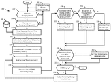
- FIG. 2 is a method of controlling a battery recharge procedure.
- FIG. 3 is an example of a current-time relationship for a recharge procedure.
- the state of charge (SOC) of the traction battery varies related to power depletion as well as recharge cycles. It may be desirable to maximize the utilization of the energy stored in the battery by converting the electric energy to propulsive power for the vehicle.
- SOC state of charge
- the vehicle When the vehicle is at rest, the vehicle can be plugged in to a utility power grid to recharge the battery.
- the rate at which a plug-in hybrid vehicle recharges from an electric charge station can be limited by station factors including the rating of the outlet the charge station.
- Examples of limitations include a 110V AC outlet with a 15 amp circuit breaker providing a maximum of about 1.4 kilowatts of charging power, or a 240V AC outlet with a 50 amp circuit breaker providing a maximum of 12 kilowatts of charging power.
- the maximum charge rate can also be reduced due to losses in converting AC current into DC current for receipt at the battery.
- an internal combustion engine turning a generator may output as much as 35 kilowatts or more.
- charging the battery using the engine as the power source can enable significantly faster charging compared to charging with a standard 110V, 15 amp AC outlet.
- a vehicle operator typically desires to maximize utilization of the electric energy from the utility company to obtain the fastest possible recharge time.
- the current applied during a battery charge cycle may be adjusted to influence the battery voltage thereby avoiding battery damage near peak charge.
- a unique recharge procedure may be implemented in a SOC range near full charge (e.g., in a range of 80-100% SOC).
- aspects of the present disclosure allow a remaining charge time prediction based on one or more non-linear recharge functions.
- other aspects include incrementing or decrementing the remaining charge time based on a difference between an actual voltage and an estimated voltage.
- the remaining charge time prediction may be adjusted based on the real-time actual charging rate to compensate for errors in the prediction on a minute by minute basis.
- FIG. 1 depicts a plug-in hybrid-electric vehicle (PHEV) 112 .
- the PHEV 112 includes one or more electric machines 114 mechanically coupled to a hybrid transmission 116 .
- the electric machines 114 may be capable of operating as a motor or a generator.
- the hybrid transmission 116 is mechanically coupled to a combustion engine 118 .
- the hybrid transmission 116 is also mechanically coupled to a drive shaft 120 that is mechanically coupled to road wheels 122 .
- the electric machines 114 can provide propulsion as well as deceleration capability either while the engine 118 is operated or turned off.
- the electric machines 114 are capable of operating as generators to provide fuel economy benefits by recovering energy that would normally be lost as heat in a friction braking system.
- the electric machines 114 may additionally impart a reaction torque against the engine output torque to generate electricity for recharging a traction battery the while the vehicle is operating.
- the electric machines 114 may further reduce vehicle emissions by allowing the engine 118 to operate near the most efficient speed and torque ranges.
- the PHEV 112 may be operated in electric-only mode using the electric machines 114 as the sole source of propulsion.
- a traction battery or battery pack 124 stores energy that can be used by the electric machines 114 .
- the battery pack 124 typically provides a high-voltage direct current (DC) output.
- One or more contactors 142 may isolate the traction battery 124 from a DC high-voltage bus 154 A when opened and couple the traction battery 124 to the DC high-voltage bus 154 A when closed.
- the traction battery 124 is electrically coupled to one or more power electronics modules 126 via the DC high-voltage bus 154 A.
- the power electronics module 126 is also electrically coupled to the electric machines 114 and provides the ability to bi-directionally transfer energy between AC high-voltage bus 154 B and the electric machines 114 .
- the traction battery 124 may provide energy for other vehicle electrical systems.
- the vehicle 112 may include a DC/DC converter module 128 that is electrically coupled to the high-voltage bus 154 .
- the DC/DC converter module 128 may be electrically coupled to a low-voltage bus 156 .
- the DC/DC converter module 128 may convert the high-voltage DC output of the traction battery 124 to a low-voltage DC supply that is compatible with low-voltage vehicle loads 152 .
- the low-voltage bus 156 may be electrically coupled to an auxiliary battery 130 (e.g., 12V battery).
- the low-voltage loads 152 may be electrically coupled to the low-voltage bus 156 .
- the low-voltage loads 152 may include various controllers within the vehicle 112 .
- the traction battery 124 of vehicle 112 may be recharged by an off-board power source 136 .
- the off-board power source 136 may be a connection to an electrical outlet.
- the external power source 136 may be electrically coupled to a charger or another type of electric vehicle supply equipment (EVSE) 138 .
- the off-board power source 136 may be an electrical power distribution network or grid as provided by an electric utility company.
- the EVSE 138 provides circuitry and controls to regulate and manage the transfer of energy between the power source 136 and the vehicle 112 .
- the off-board power source 136 may provide DC or AC electric power to the EVSE 138 .
- the EVSE 138 includes a charge connector 140 for plugging into a charge port 134 of the vehicle 112 .
- the charge port 134 may be any type of port configured to transfer power from the EVSE 138 to the vehicle 112 .
- the charge port 134 may be electrically coupled to a charger or onboard power conversion module 132 .
- the power conversion module 132 conditions power supplied from the EVSE 138 to provide the proper voltage and current levels to the traction battery 124 .
- the power conversion module 132 interfaces with the EVSE 138 to coordinate the delivery of power to the vehicle 112 .
- the EVSE connector 140 may have pins that mate with corresponding recesses of the charge port 134 .
- various components described as being electrically coupled or connected may transfer power using wireless inductive coupling or other non-contact power transfer mechanisms.
- the charge components including the charge port 134 , power conversion module 132 , power electronics module 126 , and DC-DC converter module 128 may collectively be considered part of a power interface system configured to receive power from the off-board power source 136 .
- One or more wheel brakes 144 may be provided for decelerating the vehicle 112 and preventing motion of the vehicle 112 .
- the wheel brakes 144 may be hydraulically actuated, electrically actuated, or some combination thereof.
- the wheel brakes 144 may be a part of a brake system 150 .
- the brake system 150 may include other components to operate the wheel brakes 144 .
- the brake system 150 may include a controller to monitor and coordinate operation of the brake system 150 .
- the brake system 150 monitors the brake components and controls the wheel brakes 144 for vehicle deceleration.
- the brake system 150 also responds to driver commands via brake pedal input and may also operate to automatically implement features such as stability control.
- the controller of the brake system 150 may implement a method of applying a requested brake force when requested by another controller or sub-function.
- One or more high-voltage electrical loads 146 may be coupled to the high-voltage bus 154 .
- the high-voltage electrical loads 146 may have an associated controller that operates and controls the high-voltage electrical loads 146 when appropriate.
- the high-voltage loads 146 may include compressors and electric heaters. For example, the air conditioning system may draw as much as 6 kW under high cooling loads.
- the various components discussed may have one or more associated controllers to control and monitor the operation of the components.
- the controllers may communicate via a serial bus (e.g., Controller Area Network (CAN)) or via discrete conductors.
- CAN Controller Area Network
- a vehicle system controller 148 may be present to coordinate the operation of the various components.
- the contactors 142 When the vehicle 112 is plugged in to the EVSE 138 , the contactors 142 may be in a closed state so that the traction battery 124 is coupled to the high-voltage bus 154 and to the power source 136 to charge the battery. The vehicle may be in the ignition-off condition when plugged in to the EVSE 138 .
- the System controller 148 may be implemented as one or more controllers.
- the controller 148 may monitor operating conditions of the traction battery 124 , the power conversion module 132 and the electric machine 114 .
- the traction battery 124 includes a current sensor to sense a current that flows through the traction battery 124 .
- the traction battery 124 also includes a voltage sensor to sense a voltage across terminals of the traction battery 124 .
- the voltage sensor outputs a signal indicative of the voltage across the terminals of the traction battery 124 .
- the traction battery current sensor outputs a signal indicative of a magnitude and direction of current flowing into or out of the traction battery 124 .
- the power conversion module 132 also includes a current sensor to sense a current that flows from the EVSE 138 to the traction battery 124 .
- the engine 118 coupled to the electric machine 114 generates an AC current that is converted to a DC current by the power electronics module 126 .
- the engine 118 may be controlled by a powertrain control module having at least one controller in connection with the system controller 148 .
- the current sensor of the power conversion module 132 outputs a signal indicative of a magnitude and direction of current flowing from the EVSE 138 to the traction battery 124 .
- the current sensor and voltage sensor outputs of the traction battery 124 are provided to the controller 148 .
- the controller 148 may be programmed to compute a state of charge (SOC) based on the signals from the current sensor and the voltage sensor of the traction battery 124 .
- SOC state of charge
- Various techniques may be utilized to compute the state of charge. For example, an ampere-hour integration may be implemented in which the current through the traction battery 124 is integrated over time.
- the SOC may also be estimated based on the output of the traction battery voltage sensor 104 . The specific technique utilized may depend upon the chemical composition and characteristics of the particular battery.
- the controller 148 may be configured to monitor the status the traction battery 124 .
- the controller 148 includes at least one processor that controls at least some portion of the operation of the controller 148 .
- the processor allows onboard processing of commands and executes any number of predetermined routines.
- the processor may be coupled to non-persistent storage and persistent storage.
- the non-persistent storage is random access memory (RAM) and the persistent storage is flash memory.
- RAM random access memory
- flash memory persistent (non-transitory) storage can include all forms of storage that maintain data when a computer or other device is powered down.
- the controller assesses the battery voltage at step 206 .
- the controller assesses the battery voltage. If the battery voltage is not near the battery charging voltage limit at step 202 , the method includes outputting at step 204 a remaining charge time according to traditional time calculation procedures. According to at least one example, a predetermined voltage threshold is used to determine whether battery voltage is near the charging limit.
- the controller enters a unique recharging mode to compensate for battery recharging differences when the battery is approaching a full charge.
- the method includes recalling an expected current-time relationship stored in a memory of the controller.
- the relationship is provided from an external source such as downloaded from a remote server.
- the relationship is calculated real-time using a number of algorithms based on the current operating conditions. Discussed in more detail below, it may be desirable to recharge the battery according to a predetermined recharge profile which corresponds to an expected current-time relationship.
- a plot 300 is a representation of an example current-time relationship for a recharge procedure.
- Horizontal axis 302 represents time, and vertical axis 304 represents charge current supplied to the battery for recharge.
- Curve 306 represents a profile of recharge current supplied to the battery.
- recharge current 306 is reduced as the SOC and battery voltage approach maximum values.
- the current entering the battery is modeled as an exponential function versus time, and this relationship may used to determine how much time it will take to reach a full battery charge.
- the exponential function can be predetermined, or based on present charging conditions, such as battery temperature and maximum charging current.
- a maximum current 308 is provided to the battery.
- the charge current is reduced to regulate the recharge rate of the battery until the battery is fully charged at time 310 .
- the shape of the recharge current curve 306 may vary. In this way, any number of unique current-time relationship profiles may be stored to account for various operating conditions.
- a plurality of lookup tables is stored in a memory including different current-time relationships that each correspond to a particular recharge profile.
- the controller may be programmed to store a plurality of expected current-time relationships and recall a particular recharge profile based on the vehicle operating conditions. Such profiles may be used to estimate both of an appropriate recharge current to be supplied to the battery, as well as a remaining charge time while the battery is near an SOC recharge limit or a voltage recharge limit.
- the method includes recalling an expected current-time relationship from a memory.
- a database 208 stores a plurality of unique current-time recharge curves each corresponding to different vehicle operating conditions.
- the method includes estimating a remaining charge time T R based on a current-time relationship and recharge profile corresponding to the present vehicle operating conditions.
- remaining charge time is calculated by using a predetermined equation (e.g., by integrating a current formula such as
- the percentage used for employing the exponential function can be stored at a lookup table.
- the estimated remaining charge time T R may represent the time at which the SOC is estimated to reach 100% battery SOC.
- Time may be added to the remaining charge time T R at step 214 to account for voltage and SOC variability near full charge. For example, a calibratable time (e.g., an initial value of 5 minutes) may be added to a previous remaining time estimate.
- a calibratable time e.g., an initial value of 5 minutes
- the method includes holding for a predetermined time increment T i .
- the controller is programmed to periodically compare an estimated SOC to the measured SOC at predetermined time increments.
- the time increment T i is about one minute.
- the method includes comparing the measured actual SOC to an estimated SOC based on the expected current-time relationship determined at step 212 .
- the controller calculates the estimated SOC at periodic time intervals and compares it with the actual SOC.
- the expected SOC is a percentage of the cumulative Watt-hours predicted, divided by Watt-hours at top of charge.
- the cumulative watt hours predicted may be high-voltage traction battery voltage (e.g., 350V) multiplied by a calculated battery current divided by 60 (60 minutes for 1 Watt-hour). The cumulative watt hours predicted is then added to the prior cumulative watt hours.
- the method includes assessing the direction of the discrepancy at step 224 . If at step 224 the actual SOC and remaining energy is greater than the estimated SOC and remaining energy, recharging may be proceeding faster than expected, and a greater than standard time duration is decremented from the remaining charge time at step 226 .
- the controller may be programmed to decrement the remaining charge time by a duration greater than a standard time interval in response to a negative difference between an estimated SOC and a measured actual SOC.
- the controller may periodically reduce the remaining charge time by an update decrement amount that increases as an amount that an estimated SOC is less than a measured SOC increases. This acceleration of the decrementing of the remaining charge time may account for a recharge occurring faster than the current estimate near the top of charge. According to some examples, two minutes are subtracted from the remaining charge time based on the measured actual SOC being greater than estimated SOC.
- the controller may be programmed to maintain the remaining charge time responsive to the estimated SOC being greater than the measured SOC.
- less than a standard time increment is subtracted from the remaining charge time estimate. This deceleration of the decrementing of the remaining charge time may account for a recharge occurring slower than the current estimate near the top of charge, and allow more time for additional power to be transferred to the battery.
- the method includes assessing at step 234 whether the charge procedure is still underway. If the charge is no longer underway at step 234 , the procedure ends without generating a remaining charge time display.
- the method includes generating a remaining time display estimate at step 236 .
- the method further includes looping back and re-assessing how close the actual battery parameters are relative to estimated parameters by returning to step 218 .
- the processes, methods, or algorithms disclosed herein can be deliverable to/implemented by a processing device, controller, or computer, which can include any existing programmable electronic control unit or dedicated electronic control unit.
- the processes, methods, or algorithms can be stored as data and instructions executable by a controller or computer in many forms including, but not limited to, information permanently stored on non-writable storage media such as ROM devices and information alterably stored on writeable storage media such as floppy disks, magnetic tapes, CDs, RAM devices, and other magnetic and optical media.
- the processes, methods, or algorithms can also be implemented in a software executable object.
- the processes, methods, or algorithms can be embodied in whole or in part using suitable hardware components, such as Application Specific Integrated Circuits (ASICs), Field-Programmable Gate Arrays (FPGAs), state machines, controllers or other hardware components or devices, or a combination of hardware, software and firmware components.
- suitable hardware components such as Application Specific Integrated Circuits (ASICs), Field-Programmable Gate Arrays (FPGAs), state machines, controllers or other hardware components or devices, or a combination of hardware, software and firmware components.
Landscapes
- Engineering & Computer Science (AREA)
- Power Engineering (AREA)
- Transportation (AREA)
- Mechanical Engineering (AREA)
- Life Sciences & Earth Sciences (AREA)
- Sustainable Development (AREA)
- Sustainable Energy (AREA)
- Charge And Discharge Circuits For Batteries Or The Like (AREA)
- Electric Propulsion And Braking For Vehicles (AREA)
Abstract
Description
The percentage used for employing the exponential function can be stored at a lookup table. The lookup table may be a function of time, and τ may be set to a constant value based on operating conditions (e.g., τ=8). The estimated remaining charge time TR may represent the time at which the SOC is estimated to reach 100% battery SOC.
Claims (14)
Priority Applications (3)
| Application Number | Priority Date | Filing Date | Title |
|---|---|---|---|
| US15/837,248 US10604025B2 (en) | 2017-12-11 | 2017-12-11 | Battery charging systems and methods |
| CN201811505419.7A CN110015161A (en) | 2017-12-11 | 2018-12-10 | Batter-charghing system and method |
| DE102018131645.3A DE102018131645A1 (en) | 2017-12-11 | 2018-12-10 | BATTERY CHARGING SYSTEMS AND METHOD |
Applications Claiming Priority (1)
| Application Number | Priority Date | Filing Date | Title |
|---|---|---|---|
| US15/837,248 US10604025B2 (en) | 2017-12-11 | 2017-12-11 | Battery charging systems and methods |
Publications (2)
| Publication Number | Publication Date |
|---|---|
| US20190176632A1 US20190176632A1 (en) | 2019-06-13 |
| US10604025B2 true US10604025B2 (en) | 2020-03-31 |
Family
ID=66629463
Family Applications (1)
| Application Number | Title | Priority Date | Filing Date |
|---|---|---|---|
| US15/837,248 Active 2038-05-11 US10604025B2 (en) | 2017-12-11 | 2017-12-11 | Battery charging systems and methods |
Country Status (3)
| Country | Link |
|---|---|
| US (1) | US10604025B2 (en) |
| CN (1) | CN110015161A (en) |
| DE (1) | DE102018131645A1 (en) |
Cited By (1)
| Publication number | Priority date | Publication date | Assignee | Title |
|---|---|---|---|---|
| US11161428B2 (en) * | 2019-07-01 | 2021-11-02 | Ford Global Technologies, Llc | Adaptive open circuit voltage based soc reset method at the end of charge based on temperature and charging rate |
Families Citing this family (5)
| Publication number | Priority date | Publication date | Assignee | Title |
|---|---|---|---|---|
| DE102020215328A1 (en) * | 2020-12-03 | 2022-06-09 | Vitesco Technologies GmbH | Method and device for controlling an electric drive system for an electric vehicle |
| CN111731152B (en) * | 2020-06-28 | 2021-10-29 | 中国第一汽车股份有限公司 | Power control method, device, vehicle and storage medium |
| CN114407727A (en) * | 2022-01-24 | 2022-04-29 | 四川野马汽车股份有限公司 | Method and system for estimating charging remaining time of electric automobile |
| CN114506244B (en) * | 2022-01-28 | 2023-05-23 | 重庆长安新能源汽车科技有限公司 | Estimation method and estimation system for charging remaining time of electric automobile |
| CN116872787A (en) * | 2023-08-10 | 2023-10-13 | 力高(山东)新能源技术股份有限公司 | Battery remaining charging time calculation method based on BMS charging mode |
Citations (6)
| Publication number | Priority date | Publication date | Assignee | Title |
|---|---|---|---|---|
| US20080150491A1 (en) | 2004-02-25 | 2008-06-26 | Koninklijke Philips Electronics, N.V. | Method Of Estimating The State-Of-Charge And Of The Use Time Left Of A Rechageable Battery, And Apparatus For Executing Such A Method |
| US20080197812A1 (en) * | 2007-02-16 | 2008-08-21 | O2Micro Inc. | Topology and method for dynamic charging current allocation |
| US20120098488A1 (en) * | 2009-12-21 | 2012-04-26 | Toyota Jidosha Kabushiki Kaisha | Charging system |
| US8624560B2 (en) | 2008-04-11 | 2014-01-07 | Apple Inc. | Controlling battery charging based on current, voltage and temperature |
| US20140347012A1 (en) | 2013-05-27 | 2014-11-27 | Samsung Sdi Co., Ltd. | Battery management system and method of driving the same |
| US20150066224A1 (en) | 2013-08-29 | 2015-03-05 | Honda Motor Co., Ltd | System and method for estimating a charge load |
-
2017
- 2017-12-11 US US15/837,248 patent/US10604025B2/en active Active
-
2018
- 2018-12-10 DE DE102018131645.3A patent/DE102018131645A1/en active Pending
- 2018-12-10 CN CN201811505419.7A patent/CN110015161A/en active Pending
Patent Citations (6)
| Publication number | Priority date | Publication date | Assignee | Title |
|---|---|---|---|---|
| US20080150491A1 (en) | 2004-02-25 | 2008-06-26 | Koninklijke Philips Electronics, N.V. | Method Of Estimating The State-Of-Charge And Of The Use Time Left Of A Rechageable Battery, And Apparatus For Executing Such A Method |
| US20080197812A1 (en) * | 2007-02-16 | 2008-08-21 | O2Micro Inc. | Topology and method for dynamic charging current allocation |
| US8624560B2 (en) | 2008-04-11 | 2014-01-07 | Apple Inc. | Controlling battery charging based on current, voltage and temperature |
| US20120098488A1 (en) * | 2009-12-21 | 2012-04-26 | Toyota Jidosha Kabushiki Kaisha | Charging system |
| US20140347012A1 (en) | 2013-05-27 | 2014-11-27 | Samsung Sdi Co., Ltd. | Battery management system and method of driving the same |
| US20150066224A1 (en) | 2013-08-29 | 2015-03-05 | Honda Motor Co., Ltd | System and method for estimating a charge load |
Cited By (1)
| Publication number | Priority date | Publication date | Assignee | Title |
|---|---|---|---|---|
| US11161428B2 (en) * | 2019-07-01 | 2021-11-02 | Ford Global Technologies, Llc | Adaptive open circuit voltage based soc reset method at the end of charge based on temperature and charging rate |
Also Published As
| Publication number | Publication date |
|---|---|
| CN110015161A (en) | 2019-07-16 |
| DE102018131645A1 (en) | 2019-06-13 |
| US20190176632A1 (en) | 2019-06-13 |
Similar Documents
| Publication | Publication Date | Title |
|---|---|---|
| US10604025B2 (en) | Battery charging systems and methods | |
| US10449870B2 (en) | Battery charge strategy using discharge cycle | |
| CN106842034B (en) | Estimating battery capacity in an electric vehicle | |
| US9457686B2 (en) | Method to adjust battery minimum state of charge limits based on battery power capability | |
| US9849871B2 (en) | Electric vehicle opportunistic charging systems and methods | |
| US8395355B2 (en) | Power supply system and vehicle with the system | |
| US10086709B2 (en) | Variable wakeup of a high-voltage charger based on low-voltage system parameters | |
| US9676288B2 (en) | Battery open-circuit voltage measurement using reverse current pulse | |
| US11161428B2 (en) | Adaptive open circuit voltage based soc reset method at the end of charge based on temperature and charging rate | |
| US7687934B2 (en) | System and method for managing energy use in an electric vehicle | |
| US11697355B2 (en) | Electrified vehicle electrical distribution system component protection systems and methods | |
| US10427537B2 (en) | Vehicle power supply control | |
| CN105015542A (en) | Electric vehicle control based on operating costs associated with power sources | |
| US11110809B2 (en) | Vehicle energy consumption during charging | |
| CN108656980A (en) | Off-board power transmission | |
| US9718456B2 (en) | Torque assist based on battery state of charge allocation | |
| US20160167540A1 (en) | Current Sensor for a Vehicle | |
| US10933768B2 (en) | Electrified vehicle measurement error compensating charge voltage request | |
| US11794738B2 (en) | Filtered battery current based vehicle speed limiter | |
| US11787306B2 (en) | Electrified vehicle control to reduce battery sensor heat generation | |
| US11597289B2 (en) | Electrified vehicle control of bi-directional DC/DC converter for high voltage power assist from low voltage system | |
| US20230226950A1 (en) | Vehicle battery cell balancing | |
| US20230182587A1 (en) | Current control during dc fast charging |
Legal Events
| Date | Code | Title | Description |
|---|---|---|---|
| AS | Assignment |
Owner name: FORD GLOBAL TECHNOLOGIES, LLC, MICHIGAN Free format text: ASSIGNMENT OF ASSIGNORS INTEREST;ASSIGNOR:TREHARNE, WILLIAM DAVID;REEL/FRAME:044353/0240 Effective date: 20171208 |
|
| FEPP | Fee payment procedure |
Free format text: ENTITY STATUS SET TO UNDISCOUNTED (ORIGINAL EVENT CODE: BIG.); ENTITY STATUS OF PATENT OWNER: LARGE ENTITY |
|
| STPP | Information on status: patent application and granting procedure in general |
Free format text: DOCKETED NEW CASE - READY FOR EXAMINATION |
|
| STPP | Information on status: patent application and granting procedure in general |
Free format text: NON FINAL ACTION MAILED |
|
| STPP | Information on status: patent application and granting procedure in general |
Free format text: RESPONSE TO NON-FINAL OFFICE ACTION ENTERED AND FORWARDED TO EXAMINER |
|
| STPP | Information on status: patent application and granting procedure in general |
Free format text: NOTICE OF ALLOWANCE MAILED -- APPLICATION RECEIVED IN OFFICE OF PUBLICATIONS |
|
| STPP | Information on status: patent application and granting procedure in general |
Free format text: PUBLICATIONS -- ISSUE FEE PAYMENT RECEIVED |
|
| STPP | Information on status: patent application and granting procedure in general |
Free format text: PUBLICATIONS -- ISSUE FEE PAYMENT VERIFIED |
|
| STCF | Information on status: patent grant |
Free format text: PATENTED CASE |
|
| MAFP | Maintenance fee payment |
Free format text: PAYMENT OF MAINTENANCE FEE, 4TH YEAR, LARGE ENTITY (ORIGINAL EVENT CODE: M1551); ENTITY STATUS OF PATENT OWNER: LARGE ENTITY Year of fee payment: 4 |