US10595047B2 - Wireless display subsystem and system-on-chip - Google Patents
Wireless display subsystem and system-on-chip Download PDFInfo
- Publication number
- US10595047B2 US10595047B2 US15/710,925 US201715710925A US10595047B2 US 10595047 B2 US10595047 B2 US 10595047B2 US 201715710925 A US201715710925 A US 201715710925A US 10595047 B2 US10595047 B2 US 10595047B2
- Authority
- US
- United States
- Prior art keywords
- hardware
- video
- stream
- wireless
- memory device
- Prior art date
- Legal status (The legal status is an assumption and is not a legal conclusion. Google has not performed a legal analysis and makes no representation as to the accuracy of the status listed.)
- Active, expires
Links
- 230000002194 synthesizing effect Effects 0.000 claims abstract description 8
- 238000004891 communication Methods 0.000 claims description 9
- 230000004044 response Effects 0.000 description 5
- 238000000034 method Methods 0.000 description 2
- 230000006978 adaptation Effects 0.000 description 1
- 230000002457 bidirectional effect Effects 0.000 description 1
- 239000003550 marker Substances 0.000 description 1
- 230000002123 temporal effect Effects 0.000 description 1
- 230000000007 visual effect Effects 0.000 description 1
Images


Classifications
-
- H—ELECTRICITY
- H04—ELECTRIC COMMUNICATION TECHNIQUE
- H04N—PICTORIAL COMMUNICATION, e.g. TELEVISION
- H04N21/00—Selective content distribution, e.g. interactive television or video on demand [VOD]
- H04N21/20—Servers specifically adapted for the distribution of content, e.g. VOD servers; Operations thereof
- H04N21/23—Processing of content or additional data; Elementary server operations; Server middleware
- H04N21/236—Assembling of a multiplex stream, e.g. transport stream, by combining a video stream with other content or additional data, e.g. inserting a URL [Uniform Resource Locator] into a video stream, multiplexing software data into a video stream; Remultiplexing of multiplex streams; Insertion of stuffing bits into the multiplex stream, e.g. to obtain a constant bit-rate; Assembling of a packetised elementary stream
- H04N21/2368—Multiplexing of audio and video streams
-
- H—ELECTRICITY
- H04—ELECTRIC COMMUNICATION TECHNIQUE
- H04N—PICTORIAL COMMUNICATION, e.g. TELEVISION
- H04N21/00—Selective content distribution, e.g. interactive television or video on demand [VOD]
- H04N21/40—Client devices specifically adapted for the reception of or interaction with content, e.g. set-top-box [STB]; Operations thereof
- H04N21/41—Structure of client; Structure of client peripherals
- H04N21/418—External card to be used in combination with the client device, e.g. for conditional access
-
- H—ELECTRICITY
- H04—ELECTRIC COMMUNICATION TECHNIQUE
- H04N—PICTORIAL COMMUNICATION, e.g. TELEVISION
- H04N21/00—Selective content distribution, e.g. interactive television or video on demand [VOD]
- H04N21/40—Client devices specifically adapted for the reception of or interaction with content, e.g. set-top-box [STB]; Operations thereof
- H04N21/43—Processing of content or additional data, e.g. demultiplexing additional data from a digital video stream; Elementary client operations, e.g. monitoring of home network or synchronising decoder's clock; Client middleware
- H04N21/436—Interfacing a local distribution network, e.g. communicating with another STB or one or more peripheral devices inside the home
-
- H—ELECTRICITY
- H04—ELECTRIC COMMUNICATION TECHNIQUE
- H04N—PICTORIAL COMMUNICATION, e.g. TELEVISION
- H04N19/00—Methods or arrangements for coding, decoding, compressing or decompressing digital video signals
- H04N19/65—Methods or arrangements for coding, decoding, compressing or decompressing digital video signals using error resilience
- H04N19/66—Methods or arrangements for coding, decoding, compressing or decompressing digital video signals using error resilience involving data partitioning, i.e. separation of data into packets or partitions according to importance
-
- H04L65/607—
-
- H—ELECTRICITY
- H04—ELECTRIC COMMUNICATION TECHNIQUE
- H04L—TRANSMISSION OF DIGITAL INFORMATION, e.g. TELEGRAPHIC COMMUNICATION
- H04L65/00—Network arrangements, protocols or services for supporting real-time applications in data packet communication
- H04L65/60—Network streaming of media packets
- H04L65/70—Media network packetisation
-
- H—ELECTRICITY
- H04—ELECTRIC COMMUNICATION TECHNIQUE
- H04L—TRANSMISSION OF DIGITAL INFORMATION, e.g. TELEGRAPHIC COMMUNICATION
- H04L65/00—Network arrangements, protocols or services for supporting real-time applications in data packet communication
- H04L65/60—Network streaming of media packets
- H04L65/75—Media network packet handling
- H04L65/756—Media network packet handling adapting media to device capabilities
-
- H—ELECTRICITY
- H04—ELECTRIC COMMUNICATION TECHNIQUE
- H04N—PICTORIAL COMMUNICATION, e.g. TELEVISION
- H04N19/00—Methods or arrangements for coding, decoding, compressing or decompressing digital video signals
- H04N19/10—Methods or arrangements for coding, decoding, compressing or decompressing digital video signals using adaptive coding
- H04N19/134—Methods or arrangements for coding, decoding, compressing or decompressing digital video signals using adaptive coding characterised by the element, parameter or criterion affecting or controlling the adaptive coding
- H04N19/157—Assigned coding mode, i.e. the coding mode being predefined or preselected to be further used for selection of another element or parameter
- H04N19/16—Assigned coding mode, i.e. the coding mode being predefined or preselected to be further used for selection of another element or parameter for a given display mode, e.g. for interlaced or progressive display mode
-
- H—ELECTRICITY
- H04—ELECTRIC COMMUNICATION TECHNIQUE
- H04N—PICTORIAL COMMUNICATION, e.g. TELEVISION
- H04N19/00—Methods or arrangements for coding, decoding, compressing or decompressing digital video signals
- H04N19/10—Methods or arrangements for coding, decoding, compressing or decompressing digital video signals using adaptive coding
- H04N19/169—Methods or arrangements for coding, decoding, compressing or decompressing digital video signals using adaptive coding characterised by the coding unit, i.e. the structural portion or semantic portion of the video signal being the object or the subject of the adaptive coding
- H04N19/17—Methods or arrangements for coding, decoding, compressing or decompressing digital video signals using adaptive coding characterised by the coding unit, i.e. the structural portion or semantic portion of the video signal being the object or the subject of the adaptive coding the unit being an image region, e.g. an object
- H04N19/172—Methods or arrangements for coding, decoding, compressing or decompressing digital video signals using adaptive coding characterised by the coding unit, i.e. the structural portion or semantic portion of the video signal being the object or the subject of the adaptive coding the unit being an image region, e.g. an object the region being a picture, frame or field
-
- H—ELECTRICITY
- H04—ELECTRIC COMMUNICATION TECHNIQUE
- H04N—PICTORIAL COMMUNICATION, e.g. TELEVISION
- H04N19/00—Methods or arrangements for coding, decoding, compressing or decompressing digital video signals
- H04N19/10—Methods or arrangements for coding, decoding, compressing or decompressing digital video signals using adaptive coding
- H04N19/169—Methods or arrangements for coding, decoding, compressing or decompressing digital video signals using adaptive coding characterised by the coding unit, i.e. the structural portion or semantic portion of the video signal being the object or the subject of the adaptive coding
- H04N19/17—Methods or arrangements for coding, decoding, compressing or decompressing digital video signals using adaptive coding characterised by the coding unit, i.e. the structural portion or semantic portion of the video signal being the object or the subject of the adaptive coding the unit being an image region, e.g. an object
- H04N19/176—Methods or arrangements for coding, decoding, compressing or decompressing digital video signals using adaptive coding characterised by the coding unit, i.e. the structural portion or semantic portion of the video signal being the object or the subject of the adaptive coding the unit being an image region, e.g. an object the region being a block, e.g. a macroblock
-
- H—ELECTRICITY
- H04—ELECTRIC COMMUNICATION TECHNIQUE
- H04N—PICTORIAL COMMUNICATION, e.g. TELEVISION
- H04N19/00—Methods or arrangements for coding, decoding, compressing or decompressing digital video signals
- H04N19/42—Methods or arrangements for coding, decoding, compressing or decompressing digital video signals characterised by implementation details or hardware specially adapted for video compression or decompression, e.g. dedicated software implementation
- H04N19/423—Methods or arrangements for coding, decoding, compressing or decompressing digital video signals characterised by implementation details or hardware specially adapted for video compression or decompression, e.g. dedicated software implementation characterised by memory arrangements
-
- H—ELECTRICITY
- H04—ELECTRIC COMMUNICATION TECHNIQUE
- H04N—PICTORIAL COMMUNICATION, e.g. TELEVISION
- H04N19/00—Methods or arrangements for coding, decoding, compressing or decompressing digital video signals
- H04N19/65—Methods or arrangements for coding, decoding, compressing or decompressing digital video signals using error resilience
- H04N19/68—Methods or arrangements for coding, decoding, compressing or decompressing digital video signals using error resilience involving the insertion of resynchronisation markers into the bitstream
-
- H—ELECTRICITY
- H04—ELECTRIC COMMUNICATION TECHNIQUE
- H04N—PICTORIAL COMMUNICATION, e.g. TELEVISION
- H04N21/00—Selective content distribution, e.g. interactive television or video on demand [VOD]
- H04N21/20—Servers specifically adapted for the distribution of content, e.g. VOD servers; Operations thereof
- H04N21/23—Processing of content or additional data; Elementary server operations; Server middleware
- H04N21/234—Processing of video elementary streams, e.g. splicing of video streams, manipulating MPEG-4 scene graphs
- H04N21/2343—Processing of video elementary streams, e.g. splicing of video streams, manipulating MPEG-4 scene graphs involving reformatting operations of video signals for distribution or compliance with end-user requests or end-user device requirements
-
- H—ELECTRICITY
- H04—ELECTRIC COMMUNICATION TECHNIQUE
- H04N—PICTORIAL COMMUNICATION, e.g. TELEVISION
- H04N21/00—Selective content distribution, e.g. interactive television or video on demand [VOD]
- H04N21/20—Servers specifically adapted for the distribution of content, e.g. VOD servers; Operations thereof
- H04N21/23—Processing of content or additional data; Elementary server operations; Server middleware
- H04N21/236—Assembling of a multiplex stream, e.g. transport stream, by combining a video stream with other content or additional data, e.g. inserting a URL [Uniform Resource Locator] into a video stream, multiplexing software data into a video stream; Remultiplexing of multiplex streams; Insertion of stuffing bits into the multiplex stream, e.g. to obtain a constant bit-rate; Assembling of a packetised elementary stream
- H04N21/23605—Creation or processing of packetized elementary streams [PES]
-
- H—ELECTRICITY
- H04—ELECTRIC COMMUNICATION TECHNIQUE
- H04N—PICTORIAL COMMUNICATION, e.g. TELEVISION
- H04N21/00—Selective content distribution, e.g. interactive television or video on demand [VOD]
- H04N21/20—Servers specifically adapted for the distribution of content, e.g. VOD servers; Operations thereof
- H04N21/23—Processing of content or additional data; Elementary server operations; Server middleware
- H04N21/238—Interfacing the downstream path of the transmission network, e.g. adapting the transmission rate of a video stream to network bandwidth; Processing of multiplex streams
- H04N21/2389—Multiplex stream processing, e.g. multiplex stream encrypting
-
- H—ELECTRICITY
- H04—ELECTRIC COMMUNICATION TECHNIQUE
- H04N—PICTORIAL COMMUNICATION, e.g. TELEVISION
- H04N21/00—Selective content distribution, e.g. interactive television or video on demand [VOD]
- H04N21/40—Client devices specifically adapted for the reception of or interaction with content, e.g. set-top-box [STB]; Operations thereof
- H04N21/41—Structure of client; Structure of client peripherals
- H04N21/426—Internal components of the client ; Characteristics thereof
- H04N21/42684—Client identification by a unique number or address, e.g. serial number, MAC address, socket ID
-
- H—ELECTRICITY
- H04—ELECTRIC COMMUNICATION TECHNIQUE
- H04N—PICTORIAL COMMUNICATION, e.g. TELEVISION
- H04N21/00—Selective content distribution, e.g. interactive television or video on demand [VOD]
- H04N21/40—Client devices specifically adapted for the reception of or interaction with content, e.g. set-top-box [STB]; Operations thereof
- H04N21/43—Processing of content or additional data, e.g. demultiplexing additional data from a digital video stream; Elementary client operations, e.g. monitoring of home network or synchronising decoder's clock; Client middleware
- H04N21/434—Disassembling of a multiplex stream, e.g. demultiplexing audio and video streams, extraction of additional data from a video stream; Remultiplexing of multiplex streams; Extraction or processing of SI; Disassembling of packetised elementary stream
- H04N21/4343—Extraction or processing of packetized elementary streams [PES]
-
- H—ELECTRICITY
- H04—ELECTRIC COMMUNICATION TECHNIQUE
- H04N—PICTORIAL COMMUNICATION, e.g. TELEVISION
- H04N21/00—Selective content distribution, e.g. interactive television or video on demand [VOD]
- H04N21/40—Client devices specifically adapted for the reception of or interaction with content, e.g. set-top-box [STB]; Operations thereof
- H04N21/43—Processing of content or additional data, e.g. demultiplexing additional data from a digital video stream; Elementary client operations, e.g. monitoring of home network or synchronising decoder's clock; Client middleware
- H04N21/434—Disassembling of a multiplex stream, e.g. demultiplexing audio and video streams, extraction of additional data from a video stream; Remultiplexing of multiplex streams; Extraction or processing of SI; Disassembling of packetised elementary stream
- H04N21/4347—Demultiplexing of several video streams
-
- H—ELECTRICITY
- H04—ELECTRIC COMMUNICATION TECHNIQUE
- H04N—PICTORIAL COMMUNICATION, e.g. TELEVISION
- H04N21/00—Selective content distribution, e.g. interactive television or video on demand [VOD]
- H04N21/40—Client devices specifically adapted for the reception of or interaction with content, e.g. set-top-box [STB]; Operations thereof
- H04N21/43—Processing of content or additional data, e.g. demultiplexing additional data from a digital video stream; Elementary client operations, e.g. monitoring of home network or synchronising decoder's clock; Client middleware
- H04N21/436—Interfacing a local distribution network, e.g. communicating with another STB or one or more peripheral devices inside the home
- H04N21/4363—Adapting the video or multiplex stream to a specific local network, e.g. a IEEE 1394 or Bluetooth® network
- H04N21/43637—Adapting the video or multiplex stream to a specific local network, e.g. a IEEE 1394 or Bluetooth® network involving a wireless protocol, e.g. Bluetooth, RF or wireless LAN [IEEE 802.11]
-
- H—ELECTRICITY
- H04—ELECTRIC COMMUNICATION TECHNIQUE
- H04N—PICTORIAL COMMUNICATION, e.g. TELEVISION
- H04N21/00—Selective content distribution, e.g. interactive television or video on demand [VOD]
- H04N21/40—Client devices specifically adapted for the reception of or interaction with content, e.g. set-top-box [STB]; Operations thereof
- H04N21/43—Processing of content or additional data, e.g. demultiplexing additional data from a digital video stream; Elementary client operations, e.g. monitoring of home network or synchronising decoder's clock; Client middleware
- H04N21/44—Processing of video elementary streams, e.g. splicing a video clip retrieved from local storage with an incoming video stream, rendering scenes according to MPEG-4 scene graphs
- H04N21/4408—Processing of video elementary streams, e.g. splicing a video clip retrieved from local storage with an incoming video stream, rendering scenes according to MPEG-4 scene graphs involving video stream encryption, e.g. re-encrypting a decrypted video stream for redistribution in a home network
-
- H—ELECTRICITY
- H04—ELECTRIC COMMUNICATION TECHNIQUE
- H04N—PICTORIAL COMMUNICATION, e.g. TELEVISION
- H04N5/00—Details of television systems
- H04N5/44—Receiver circuitry for the reception of television signals according to analogue transmission standards
-
- G—PHYSICS
- G09—EDUCATION; CRYPTOGRAPHY; DISPLAY; ADVERTISING; SEALS
- G09G—ARRANGEMENTS OR CIRCUITS FOR CONTROL OF INDICATING DEVICES USING STATIC MEANS TO PRESENT VARIABLE INFORMATION
- G09G2310/00—Command of the display device
- G09G2310/02—Addressing, scanning or driving the display screen or processing steps related thereto
- G09G2310/0264—Details of driving circuits
- G09G2310/0297—Special arrangements with multiplexing or demultiplexing of display data in the drivers for data electrodes, in a pre-processing circuitry delivering display data to said drivers or in the matrix panel, e.g. multiplexing plural data signals to one D/A converter or demultiplexing the D/A converter output to multiple columns
-
- G—PHYSICS
- G09—EDUCATION; CRYPTOGRAPHY; DISPLAY; ADVERTISING; SEALS
- G09G—ARRANGEMENTS OR CIRCUITS FOR CONTROL OF INDICATING DEVICES USING STATIC MEANS TO PRESENT VARIABLE INFORMATION
- G09G2370/00—Aspects of data communication
- G09G2370/16—Use of wireless transmission of display information
Definitions
- One or more embodiments described herein relate to a wireless display subsystem and a system-on-chip including a wireless display subsystem.
- Wireless display techniques have been developed to control the wireless transfer of video and/or audio data from an electronic device (e.g., mobile device) to an external display device.
- the video and/or audio data are processed to place them in a form suitable for wireless transfer.
- this data processing introduces a delay that increases the response time to inputs on the mobile device.
- the increase in response time produces a time lag (e.g., latency) in displaying information in response to the inputs.
- a wireless display subsystem includes a hardware composition generator to read video data from a memory device and generate video frame data by synthesizing the video data; a hardware video encoder to receive the video frame data in an on-the-fly (OTF) manner from the hardware composition generator and generate a video stream by encoding the video frame data; and a wireless hardware transport stream multiplexer to receive the video stream in the OTF manner from the hardware video encoder, read an audio stream from the memory device, multiplex the video stream and the audio stream, and generate a wireless display packet by packetizing the multiplexed video and audio streams.
- OTF on-the-fly
- a system-on-chip (SOC) coupled to a memory device, the SOC including at least one processor and a wireless display subsystem, the wireless display subsystem including a hardware composition generator to read video data from the memory device and generate video frame data by synthesizing the video data; a hardware video encoder implemented to receive the video frame data in an on-the-fly (OTF) manner from the hardware composition generator and generate a video stream by encoding the video frame data; and a wireless hardware transport stream multiplexer to receive the video stream in the OTF manner from the hardware video encoder, read an audio stream from the memory device, multiplex the video stream and the audio stream, and generate a wireless display packet by packetizing the multiplexed video and audio streams.
- OTF on-the-fly
- a wireless display subsystem includes first hardware to generate video frame data; second hardware to receive the video frame data in an on-the-fly manner from the first hardware and encode the video frame data to form a video stream; and third hardware to receive the video stream in the on-the-fly manner from the second hardware, read an audio stream, multiplex the video stream and the audio stream, and packetizing the multiplexed video and audio streams to generate a wireless display packet.
- FIG. 1 illustrates an embodiment of a wireless display subsystem
- FIG. 2 illustrates an embodiment of a hardware composition generator
- FIGS. 3A and 3B illustrate examples of data formats of video frame data output from the hardware composition generator
- FIG. 4 illustrates another example of a data format of video frame data output from the hardware composition generator
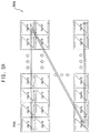
- FIG. 5A and 5B illustrate embodiments of output orders of image data in video frame data output from the hardware composition generator
- FIG. 6 illustrates an embodiment of a hardware video encoder
- FIG. 7 illustrates an example of a video stream output from the hardware video encoder
- FIG. 8 illustrates an embodiment of a wireless hardware transport stream multiplexer
- FIG. 9 illustrates an example where a wireless display subsystem requests a wireless transmitter to transfer a wireless display packet
- FIG. 10 illustrates another embodiment of a wireless display subsystem
- FIG. 11A illustrates operation of a wireless display subsystem in game mode according to an embodiment
- FIG. 11B illustrates operation of a wireless display subsystem in a non-game mode according to an embodiment
- FIG. 12 illustrates an embodiment of an electronic device including a system-on-chip.
- FIG. 1 illustrates an embodiment of a wireless display subsystem 100 which includes a hardware composition generator 120 , a hardware video encoder 140 , and a wireless hardware transport stream multiplexer 160 , which, for example, may be implemented as hardware or hardware engines.
- the hardware composition generator 120 may read video data VD from a memory device 200 .
- the video data VD may be written to the memory device 200 by any video source 210 .
- the video source 210 may be, for example, a graphics processing unit (GPU) that performs any graphics processing, a central processing unit (CPU), or an application processor (AP) that executes any application, an external storage device such as a flash memory, or a communication device that receives the video data VD through wired or wireless communications.
- GPU graphics processing unit
- CPU central processing unit
- AP application processor
- the hardware composition generator 120 may generate video frame data VFD by synthesizing the video data VD.
- the video data VD may be, for example, data corresponding to one or more image layers.
- the hardware composition generator 120 may generate video frame data VFD by synthesizing the image layers so that the image layers overlap.
- the video frame data VFD may include frame synchronization information per frame.
- the frame synchronization information may include at least one of a frame start indication, a frame end indication, or a timestamp.
- the hardware video encoder 140 may receive the video frame data VFD in an on-the-fly (OTF) manner from the hardware composition generator 120 .
- OTF on-the-fly
- Data transfer in the OTF manner between components or elements of the wireless display subsystem 100 may corresponding to the case where data output from one component are directly transferred to another component, without being stored in the memory device 200 .
- data generated by one component may be transferred to another component in substantially real time. That is, the video frame data VFD output from the hardware composition generator 120 may be directly transferred to the hardware video encoder 140 without being stored in the memory device 200 .
- the hardware video encoder 140 may generate a video stream VBS by encoding the video frame data VFD.
- the video stream VBS may include the frame synchronization information (e.g., the frame start indication, the frame end indication, and/or the timestamp) per frame. Since each of the video frame data VFD transferred between the hardware composition generator 120 and the hardware video encoder 140 and the video stream VBS transferred between the hardware video encoder 140 and the wireless hardware transport stream multiplexer 160 has the frame synchronization information including (e.g., at least one of the frame start indication, the frame end indication, or the timestamp), data may be processed in an accurate order in the wireless display subsystem 100 . Also, synchronization between components 120 , 140 , 170 and 180 may be ensured.
- the wireless hardware transport stream multiplexer 160 may receive the video stream VBS in the OTF manner from the hardware video encoder 140 .
- the video stream VBS output from the hardware video encoder 140 may be directly transferred to the wireless hardware transport stream multiplexer 160 without being stored in the memory device 200 .
- the wireless hardware transport stream multiplexer 160 may read an audio stream from the memory device 200 .
- the audio stream may be audio data AD written to the memory device 200 by any audio source 220 .
- the audio stream may be encoded audio data EAD generated by encoding the audio data AD by an audio encoder (e.g., a software audio encoder) 230 .
- the wireless hardware transport stream multiplexer 160 may multiplex the video stream VBS and the audio stream EAD, and may generate a wireless display packet WDP by packetizing the multiplexed video and audio streams VBS and EAD.
- the wireless hardware transport stream multiplexer 160 may include a hardware packetizer 180 that performs multiplexing and packetizing on the video stream VBS and the audio stream EAD.
- the wireless hardware transport stream multiplexer 160 may further include a hardware encryptor 170 that performs encryption on the video stream VBS and the audio stream EAD.
- the hardware encryptor 170 may perform high-bandwidth digital content protection (HDCP) encryption.
- HDCP high-bandwidth digital content protection
- the hardware packetizer 180 may perform multiplexing and packetizing on the encrypted video and audio streams VBS and EAD.
- the wireless display packet WDP generated by the wireless hardware transport stream multiplexer 160 may be wirelessly transferred to an external wireless display device through a wireless transmitter 260 and an antenna 270 .
- the wireless transmitter 260 may be, for example, a wireless-fidelity (Wi-Fi) transmitter, a wireless local area network (WLAN) transmitter, a bluetooth transmitter, a near field communication (NFC) transmitter, or another wireless communication transmitter.
- the wireless display packet WDP generated by the wireless hardware transport stream multiplexer 160 may be directly transferred to the wireless transmitter 260 .
- the wireless hardware transport stream multiplexer 160 may write the wireless display packet WDP to the memory device 200 , and the wireless transmitter 260 may read the wireless display packet WDP from the memory device 200 .
- all or a portion of components that convert video data VD to a wireless display packet WDP suitable for wireless transfer are implemented as software. Accordingly, the proposed electronic device may have a large latency in wireless display data transfer.
- the components that convert the video data VD to the wireless display packet WDP suitable for the wireless transfer e.g., the hardware composition generator 120 , the hardware video encoder 140 , the hardware encryptor 170 and the hardware packetizer 180 ) may be implemented as hardware. Accordingly, an electronic device including the wireless display subsystem 100 may reduce the latency of the wireless display data transfer.
- each component performs processing (e.g., composition, encoding, encryption, or the like) on data stored in the memory device 200 and stores results of the processing again in the memory device, which may be referred to as a memory-to-memory (M2M) operation. Subsequently, the next component also receives the results of the processing from the memory device 200 .
- processing e.g., composition, encoding, encryption, or the like
- M2M memory-to-memory
- the data transfer between the components may be performed in the OTF manner without using the memory device 200 .
- processing results of each component may not be stored in the memory device 200 and may be directly transferred to the next component in substantially real time.
- the wireless display subsystem 100 forms an OTF path from the hardware composition generator 120 to the hardware packetizer 180 , the electronic device including the wireless display subsystem 100 according to example embodiments may further reduce the latency of the wireless display data transfer.
- FIG. 2 illustrates an embodiment of a hardware composition generator, which, for example, may correspond to the hardware composition generator 120 in the wireless display subsystem of FIG. 1 .
- the hardware composition generator 120 is implemented as hardware which includes a direct memory access (DMA) interface 122 , a composition engine 124 and an OTF interface 126 .
- the DMA interface 122 may perform an access operation to a memory device.
- the DMA interface 122 may receive video data VD from the memory device.
- the video data VD may be data corresponding to one or more image layers and/or one or more image objects.
- the composition engine 124 may generate video frame data VFD based on the video data VD received through the DMA interface 122 .
- the composition engine 124 may generate the video frame data VFD corresponding to one frame by synthesizing the video data VD, so that the image layers and/or image objects overlap.
- the composition engine 124 may include a display data processor, a display and enhancement controller, or the like, but is not limited thereto.
- the OTF interface 126 may directly transfer the video frame data VFD generated by the composition engine 124 to a hardware video encoder.
- FIGS. 3A and 3B illustrate examples of data formats of video frame data output from a hardware composition generator, e.g., a hardware composition generator 120 .
- video frame data output from the hardware composition generator may have a data format in a packet form including control bits CB and data bits DB.
- each packet 310 , 320 , 330 a , 335 a and 340 of the video frame data may include thirty data bits DB and two control bits CB.
- the control bits CB may indicate a frame start, a data transfer or a frame end.
- the packets 310 , 320 , 330 a , 335 a and 340 of the video frame data may be classified into frame start packets 310 and 320 , data transfer packets 330 a and 335 a , and frame end packets 340 according to the control bits CB.
- the frame start packets 310 and 320 may include, as the data bits DB, a timestamp TS representing time information of each frame.
- a first frame start packet 310 may have the control bits CB of ‘01’ and may include, as the data bits DB, thirty bits of the 33-bit timestamp TS.
- a second frame start packet 320 may have the control bits CB of ‘10’ and may include, as the data bits DB, the remaining three bits of the 33-bit timestamp TS.
- Each data transfer packet 330 a and 335 a may have the control bits CB of ‘00’, and may include, as the data bits DB, image data (e.g., YUV data).
- a first data transfer packet 330 a may include, as the data bits DB, two 8-bit Y data (or luminance data) and one 8-bit U data (or chrominance data)
- a second data transfer packet 335 a may include, as the data bits DB, two 8-bit Y data and one 8-bit V data (or chrominance data).
- the first data transfer packet 330 a and the second data transfer packet 335 a may be alternately transferred.
- FIG. 3A illustrates an example of the data format of the video frame data including 4:1:1 YUV data as the image data, the image data of the video frame data are not limited thereto.
- the frame end packet 340 may have the control bits CB of ‘11’.
- the data format in FIG. 3B may be substantially the same as the data format in FIG. 3A , except that each data transfer packet 330 b and 330 b includes 10-bit Y, U or V data.
- a first data transfer packet 330 b may include, as the data bits DB, two 10-bit Y data and one 10-bit U data
- a second data transfer packet 335 b may include, as the data bits DB, two 10-bit Y data and one 10-bit V data.
- the first data transfer packet 330 b and the second data transfer packet 335 b may be alternately transferred.
- FIG. 4 illustrates an example of a data format of video frame data output from a hardware composition generator, e.g., a hardware composition generator 120 .
- FIG. 5A illustrates an example of an output order of image data included in video frame data output from a hardware composition generator.
- FIG. 5B illustrates another example of an output order of image data included in video frame data output from a hardware composition generator, e.g., a hardware composition generator 120 .
- FIG. 4 illustrates an example for transferring video frame data 300 having the data format in FIG. 3B for one frame.
- First and second frame start packets 310 and 320 including a timestamp TS may be first transferred.
- a first data transfer packet 330 b including two 10-bit Y data and one 10-bit U data and a second data transfer packet 335 b including two 10-bit Y data and one 10-bit V data may be alternately transferred.
- the video frame data 300 corresponding to one frame may include 4N Y data Y 0 through Y(4N- 1 ), N U data U 0 through U(N- 1 ) and N V data V 0 through V(N- 1 ).
- a hardware composition generator may divide each frame into macro blocks on each of which a hardware video encoder performs encoding, and may transfer the video frame data 300 to the hardware video encoder on a macro block unit basis.
- the hardware composition generator may divide one frame 300 a into a plurality of macro blocks 350 a , each including 16*16 pixels.
- the hardware composition generator may sequentially transfer image data for the macro blocks 350 a to the hardware video encoder.
- the hardware composition generator may first transfer the data transfer packets 330 b and 335 b including the image data for one macro block 350 a , and then may transfer the data transfer packets 330 b and 335 b including the image data for the next macro block 350 a .
- FIG. 5A the hardware composition generator may divide one frame 300 a into a plurality of macro blocks 350 a , each including 16*16 pixels.
- the hardware composition generator may sequentially transfer image data for the macro blocks 350 a to the hardware video encoder.
- the hardware composition generator may first transfer the data transfer packets 330 b and 335 b including the image data for one macro block 350 a , and then may transfer the data transfer packets 330 b and 335 b including the image data for the next macro block 350 a
- the hardware composition generator may transfer the image data for the pixels in a raster scan order with respect to each macro block 350 a , and may transfer the image data for the macro blocks 350 a also in the raster scan order with respect to one frame 300 a.
- the hardware composition generator may divide one frame 300 b into a plurality of macro blocks 350 b each including 32*32 pixels, and may sequentially transfer the image data for the macro blocks 350 b to the hardware video encoder.
- the sizes of macro blocks 350 a and 350 b may be different in another embodiment.
- the hardware composition generator may transfer a frame end packet 340 to the hardware video encoder.
- FIG. 6 illustrates an embodiment of the hardware video encoder 140 in the wireless display subsystem of FIG. 1 .
- the hardware video encoder 140 is implemented as hardware which includes an input OTF interface 141 , an encoding engine 142 and an output OTF interface 143 .
- the input OTF interface 141 may directly receive video frame data VFD from a hardware composition generator.
- the encoding engine 142 may generate a video stream VBS by encoding the video frame data VFD received through the input OTF interface 141 .
- the encoding engine 142 may perform intra-mode (e.g., I-mode) encoding for reducing a spatial redundancy within one frame, one macro block or one slice, and/or inter-mode (e.g., unidirectional predictive P-mode or bidirectional predictive B-mode) encoding for reducing a temporal redundancy between adjacent frames, macro blocks or slices.
- intra-mode e.g., I-mode
- inter-mode e.g., unidirectional predictive P-mode or bidirectional predictive B-mode
- the encoding engine 142 may include a pipeline control unit 150 , a motion estimation unit 151 , a motion compensation unit 152 , an intra prediction and transform unit 153 , an intra mode decision unit 154 , a deblock filter 155 , a pixel cache 156 and a bitstream processing unit 157 .
- the encoding engine 142 may have a different configuration in another embodiment.
- the output OTF interface 143 may directly transfer the video stream VBS generated by the encoding engine 142 to a wireless hardware transport stream multiplexer.
- FIG. 7 illustrates an example of a video stream VBS output from a hardware video encoder.
- the video stream VBS may have a data format in a form of packets 410 , 420 , 430 and 440 , each including one flag bit FB and sixty four data bits.
- the flag bit FB may indicate information corresponding to at least one of the data bits, a frame start, a slice start, a data transfer, a slice end, or a frame end.
- the flag bit FB of ‘0’ may indicate a data transfer or may indicate a slice start along with the data transfer.
- the flag bit FB of ‘1’ may indicate a frame start, slice end, or frame end.
- a packet 410 including the flag bit FB of ‘1’ and the data bits [63:62] of ‘00’ may be a frame start packet and may include, as data bits, a timestamp TS representing time information of each frame.
- a packet 420 including the flag bit FB of ‘0’ may be a data transfer packet and may include, as the data bits, a bitstream BS of encoded image data for each slice.
- a packet 430 including the flag bit FB of ‘1’ and data bits [63:62] of ‘01’ may be a slice end packet.
- the data transfer packet 420 next to the frame start packet 410 or the slice end packet 430 may indicate the slice start along with the data transfer.
- a frame end packet 440 including the flag bit FB of ‘1’ and the data bits [63:62] of ‘10’ may be transferred.
- FIG. 8 illustrates an embodiment of the wireless hardware transport stream multiplexer 160 in the wireless display subsystem of FIG. 1 .
- the wireless hardware transport stream multiplexer 160 may be implemented as hardware which includes an input OTF interface 162 , a DMA interface 164 , a multiplexer 166 , a hardware encryptor 170 and a hardware packetizer 180 .
- the input OTF interface 162 may directly receive a video stream VBS from a hardware video encoder.
- the DMA interface 164 may receive an audio stream EAD from a memory device.
- the multiplexer 166 may selectively output, as a payload PL to be packetized to a wireless display packet WDP, the video stream VBS received through the input OTF interface 162 or the audio stream EAD received through the DMA interface 164 .
- the hardware encryptor 170 may perform encryption (e.g., HDCP encryption) on the payload PL from the multiplexer 166 and may output an encrypted payload EPL.
- the hardware packetizer 180 may packetize the encrypted payload EPL output from the hardware encryptor 170 to the wireless display packet WDP.
- the hardware packetizer 180 may include a packetized elementary stream (PES) packetizer 182 , a transport stream (TS) packetizer 184 , and a real-time transport protocol (RTP) packetizer 186 .
- the packetized elementary stream (PES) packetizer 182 packetizes the encrypted payload EPL to a PES packet by adding a PES header to the encrypted payload EPL.
- the transport stream (TS) packetizer 184 packetizes at least one PES packet to a TS packet by adding a TS header to the at least one PES packet.
- the real-time transport protocol (RTP) packetizer 186 packetizes at least one TS packet to a RTP packet (or the wireless display packet WDP) by adding a RTP header to the at least one TS packet.
- the PES header may include, but is not limited to, a packet start code prefix, a stream ID, a PES packet length, etc.
- the TS header may include, but is not limited to, a sync byte, a transport error indicator, a payload unit start indicator, a transport priority, a packet ID, a transport scrambling control, an adaptation field control, a continuity counter, etc.
- the RTP header may include, but is not limited to, a version, a padding, an extension, a contributing source (CSRC) count, a marker, a payload type, a sequence number, a timestamp, a synchronization source (SSRC), etc.
- the wireless display packet WDP generated by the hardware packetizer 180 may be written to the memory device through the DMA interface 164 .
- FIG. 9 illustrates an example where the wireless display subsystem 100 requests a wireless transmitter to transfer a wireless display packet.
- a wireless display packet WDP generated by a wireless display subsystem 100 may be written to a region 250 of a memory device 200 .
- the wireless display subsystem 100 (or the wireless hardware transport stream multiplexer) may request a wireless transmitter 260 to wirelessly transfer the wireless display packet WDP before the entire wireless display packet(s) WDP corresponding to one frame is written to the memory region 250 .
- the wireless display subsystem 100 may divide one frame into a plurality of slices and may request the wireless transmitter 260 to wirelessly transfer the wireless display packet WDP_SLICE each time the wireless display packet WDP_SLICE corresponding to one slice is written to memory region 250 or the memory device 200 .
- the wireless display subsystem 100 (or the wireless hardware transport stream multiplexer) may generate an interrupt signal INT each time the wireless display packet WDP_SLICE corresponding to one slice is written to the memory device 200 .
- a wireless communication subsystem 262 may control a radio frequency (RF) integrated circuit 264 to wirelessly transfer the wireless display packet WDP_SLICE in response to the interrupt signal INT.
- the RF integrated circuit 264 may transfer the wireless display packet WDP_SLICE to an external wireless display device through an antenna 270 .
- RF radio frequency
- FIG. 10 illustrates another embodiment of a wireless display subsystem 100 a which has a similar configuration to wireless display subsystem 100 of FIG. 1 , except that a wireless hardware transport stream multiplexer 160 a further reads an auxiliary stream AUXD from a memory device 200 .
- the wireless hardware transport stream multiplexer 160 a may receive not only a video stream VBS and an audio stream EAD, but also the auxiliary stream AUXD.
- the auxiliary stream AUXD may include still image data, e.g., joint photographic experts group (JPEG) data, portable network graphics (PNG) data, etc.
- the auxiliary stream AUXD may include moving image data, e.g., H.264 data.
- the auxiliary stream AUXD may include data different from or in addition to still and moving image data in other embodiments.
- the wireless hardware transport stream multiplexer 160 a may multiplex the video stream VBS, the audio stream EAD, and the auxiliary stream AUXD, and may generate a wireless display packet WDP by packetizing the multiplexed video, audio, and auxiliary streams VBS, EAD and AUXD.
- a hardware encryptor 170 a may perform encryption on the video stream VBS, the audio stream EAD, and the auxiliary stream AUXD
- a hardware packetizer 180 may perform multiplexing and packetizing on the encrypted video, audio and auxiliary streams VBS, EAD and AUXD.
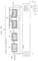
- FIG. 11A illustrates an example of an operation of a wireless display subsystem 100 b in a game mode
- FIG. 11B illustrates an example of an operation of the wireless display subsystem 100 b in a non-game mode.
- the wireless display subsystem 100 b of FIGS. 11A and 11B may have a similar configuration to that of a wireless display subsystem 100 of FIG. 1 , except that the wireless display subsystem 100 b receives a mode signal SMODE.
- the wireless display subsystem 100 b may receive a mode signal SMODE indicating a game mode or a non-game mode. As illustrated in FIG. 11A , when the mode signal SMODE indicates the game mode, a hardware composition generator 120 b , a hardware video encoder 140 b , and a wireless hardware transport stream multiplexer 160 b (e.g., hardware encryptor 170 b and hardware packetizer 180 b ) may perform a data transfer in an OTF manner without using a memory device 200 , as described above with reference to FIG. 1 .
- the hardware composition generator 120 b when the mode signal SMODE indicates the non-game mode, the hardware composition generator 120 b , the hardware video encoder 140 b , and the wireless hardware transport stream multiplexer 160 b (e.g., hardware encryptor 170 b and hardware packetizer 180 b ) may perform the data transfer in a M2M manner (which is a data transfer manner in one type of proposed wireless display subsystem) using memory device 200 .
- M2M manner which is a data transfer manner in one type of proposed wireless display subsystem
- the hardware composition generator 120 b may read video data VD from the memory device 200 to receive an input and may write video frame data VFD to the memory device 200 to provide an output.
- the hardware video encoder 140 b may read the video frame data VFD from the memory device 200 to receive an input and may write a video stream VBS to the memory device 200 to provide an output.
- the hardware encryptor 170 b may read the video stream VBS (along with audio and/or auxiliary streams) from the memory device 200 to receive an input and write an encrypted payload EPL to the memory device 200 to provide an output.
- the hardware packetizer 180 b may read the encrypted payload EPL from the memory device 200 to receive an input and may write a wireless display packet WDP to the memory device 200 to provide an output.
- the wireless display subsystem 100 b may operate like the proposed wireless display subsystem in the non-game mode and may generate the wireless display packet WDP in the OTF manner in the game mode, in order to rapidly transfer the wireless display packet WDP to an external wireless display device. Accordingly, when an electronic device including the wireless display subsystem 100 b operates in the game mode, a visual (and/or aural) response to an input of a user to the electronic device may be rapidly displayed at the external wireless display device.
- the hardware video encoder 140 b may only perform encoding on the video frame data VFD. However, when the mode signal SMODE indicates the non-game mode, the hardware video encoder 140 b may perform not only encoding on the video frame data VFD but also decoding on other video data (e.g., data for video played at the electronic device including wireless display subsystem 100 b ) in a time divisional manner. Accordingly, the hardware video encoder 140 b may serve as an encoder for the wireless display data transfer and may also serve as a decoder for the video playback at the same time.
- the hardware video encoder 140 b may serve as an encoder for the wireless display data transfer and may also serve as a decoder for the video playback at the same time.
- FIG. 12 illustrates an embodiment of an electronic device 500 including a system-on-chip (SOC) 510 .
- the electronic device 500 may include a memory device 200 , the SOC 510 coupled to the memory device 200 , an RF integrated circuit 264 , and a transmitting antenna 270 .
- the electronic device 500 may be any mobile device including, but not limited to, a smart phone, a mobile phone, a tablet computer, a laptop computer, a digital camera, a portable game console, an MP3 player, a personal digital assistants (PDA), a portable multimedia player (PMP), etc.
- PDA personal digital assistants
- PMP portable multimedia player
- the SOC 510 may include a processor 520 (e.g., a CPU, an AP, etc.) and a wireless display subsystem 100 .
- the wireless display subsystem 100 may include a hardware composition generator, a hardware video encoder and a wireless hardware transport stream multiplexer implemented as hardware, and may perform a data transfer in an OTF manner between the hardware composition generator, the hardware video encoder, and the wireless hardware transport stream multiplexer. Accordingly, the wireless display subsystem 100 may reduce latency of a wireless display data transfer.
- the SOC 510 may further include a wireless communication subsystem 262 that controls the RF integrated circuit 264 to wirelessly transfer a wireless display packet generated by the wireless display subsystem 100 to a wireless display device 550 .
- the wireless communication subsystem 262 may include, for example, a Wi-Fi subsystem, a WLAN subsystem, and/or a Bluetooth subsystem.
- the RF integrated circuit 264 controlled by the wireless communication subsystem 262 may wirelessly transfer the wireless display packet through the transmitting antenna 270 .
- the wireless display device 550 may receive the wireless display packet through a receiving antenna 570 , and may output a video and/or an audio based on the wireless display packet.
- the embodiments described herein may be applied, for example, to any SOC and any electronic device including the SOC.
- the electronic device include but are not limited to a smart phone, a mobile phone, a tablet computer, a laptop computer, a personal computer, an MP3 player, a PDA, a PMP, a digital TV, a digital camera, portable game console, etc.
Abstract
Description
Claims (18)
Applications Claiming Priority (2)
| Application Number | Priority Date | Filing Date | Title |
|---|---|---|---|
| KR1020170004611A KR102581438B1 (en) | 2017-01-12 | 2017-01-12 | Wireless display subsystem and system-on-chip |
| KR10-2017-0004611 | 2017-01-12 |
Publications (2)
| Publication Number | Publication Date |
|---|---|
| US20180199068A1 US20180199068A1 (en) | 2018-07-12 |
| US10595047B2 true US10595047B2 (en) | 2020-03-17 |
Family
ID=62783733
Family Applications (1)
| Application Number | Title | Priority Date | Filing Date |
|---|---|---|---|
| US15/710,925 Active 2037-09-27 US10595047B2 (en) | 2017-01-12 | 2017-09-21 | Wireless display subsystem and system-on-chip |
Country Status (3)
| Country | Link |
|---|---|
| US (1) | US10595047B2 (en) |
| KR (1) | KR102581438B1 (en) |
| CN (1) | CN108307201B (en) |
Families Citing this family (1)
| Publication number | Priority date | Publication date | Assignee | Title |
|---|---|---|---|---|
| CN114697744B (en) * | 2020-12-28 | 2023-12-19 | 海能达通信股份有限公司 | Video data processing method and related device |
Citations (16)
| Publication number | Priority date | Publication date | Assignee | Title |
|---|---|---|---|---|
| US7565677B1 (en) * | 2003-04-21 | 2009-07-21 | Microsoft Corporation | Method and apparatus for managing a data carousel |
| US20110107057A1 (en) * | 2009-10-29 | 2011-05-05 | Petolino Jr Joseph A | Address translation unit with multiple virtual queues |
| US20110158604A1 (en) * | 2008-12-26 | 2011-06-30 | Taiji Sasaki | Recording medium, reproduction device, and integrated circuit |
| US8019883B1 (en) * | 2005-05-05 | 2011-09-13 | Digital Display Innovations, Llc | WiFi peripheral mode display system |
| US20110276710A1 (en) * | 2010-05-05 | 2011-11-10 | Cavium Networks | System and method for low-latency multimedia streaming |
| US20120054806A1 (en) | 2010-08-28 | 2012-03-01 | Zvi Reznic | Methods circuits & systems for wireless video transmission |
| US20120243602A1 (en) | 2010-09-23 | 2012-09-27 | Qualcomm Incorporated | Method and apparatus for pipelined slicing for wireless display |
| US20130257687A1 (en) | 2012-03-30 | 2013-10-03 | Samsung Electronics Co., Ltd. | Display system, display device, and related methods of operation |
| US8700796B2 (en) | 2010-09-22 | 2014-04-15 | Qualcomm Incorporated | MAC data service enhancements |
| US20140233732A1 (en) * | 2013-02-21 | 2014-08-21 | Broadcom Corporation | Mobile paytv drm architecture |
| US8917608B2 (en) | 2012-01-31 | 2014-12-23 | Qualcomm Incorporated | Low latency WiFi display using intelligent aggregation |
| US20150036695A1 (en) | 2013-07-31 | 2015-02-05 | Nvidia Corporation | Real time network adaptive low latency transport stream muxing of audio/video streams for miracast |
| US20150295982A1 (en) | 2014-04-10 | 2015-10-15 | Qualcomm Incorporated | Streaming control for real-time transport protocol |
| US20160286260A1 (en) * | 2015-03-24 | 2016-09-29 | Intel Corporation | Distributed media stream synchronization control |
| US20180227539A1 (en) * | 2014-12-14 | 2018-08-09 | SZ DJI Technology Co., Ltd. | System and method for supporting selective backtracking data recording |
| US20190089927A1 (en) * | 2017-09-20 | 2019-03-21 | Qualcomm Incorporated | Block-based power efficient timing engine for smart display panels |
Family Cites Families (7)
| Publication number | Priority date | Publication date | Assignee | Title |
|---|---|---|---|---|
| US7450600B2 (en) * | 2003-04-21 | 2008-11-11 | Microsoft Corporation | Method and apparatus for managing a data carousel |
| JP4983147B2 (en) * | 2006-08-18 | 2012-07-25 | 富士通セミコンダクター株式会社 | Multiplexing device, multiplexing method, and multiplexing program |
| WO2008130367A1 (en) * | 2007-04-19 | 2008-10-30 | Thomson Licensing | Adaptive reference picture data generation for intra prediction |
| JP5410720B2 (en) * | 2008-09-25 | 2014-02-05 | 日立コンシューマエレクトロニクス株式会社 | Digital information signal transmitting / receiving apparatus and digital information signal transmitting / receiving method |
| EP2264642B1 (en) * | 2009-06-02 | 2014-02-26 | Vodafone Holding GmbH | Data exchange with a man-machine-device using short range radio communication |
| CN104040542B (en) * | 2011-12-08 | 2017-10-10 | 甲骨文国际公司 | For the technology for the column vector that relational data is kept in volatile memory |
| US9749682B2 (en) * | 2015-06-09 | 2017-08-29 | Qualcomm Incorporated | Tunneling HDMI data over wireless connections |
-
2017
- 2017-01-12 KR KR1020170004611A patent/KR102581438B1/en active IP Right Grant
- 2017-09-21 US US15/710,925 patent/US10595047B2/en active Active
-
2018
- 2018-01-05 CN CN201810010828.3A patent/CN108307201B/en active Active
Patent Citations (16)
| Publication number | Priority date | Publication date | Assignee | Title |
|---|---|---|---|---|
| US7565677B1 (en) * | 2003-04-21 | 2009-07-21 | Microsoft Corporation | Method and apparatus for managing a data carousel |
| US8019883B1 (en) * | 2005-05-05 | 2011-09-13 | Digital Display Innovations, Llc | WiFi peripheral mode display system |
| US20110158604A1 (en) * | 2008-12-26 | 2011-06-30 | Taiji Sasaki | Recording medium, reproduction device, and integrated circuit |
| US20110107057A1 (en) * | 2009-10-29 | 2011-05-05 | Petolino Jr Joseph A | Address translation unit with multiple virtual queues |
| US20110276710A1 (en) * | 2010-05-05 | 2011-11-10 | Cavium Networks | System and method for low-latency multimedia streaming |
| US20120054806A1 (en) | 2010-08-28 | 2012-03-01 | Zvi Reznic | Methods circuits & systems for wireless video transmission |
| US8700796B2 (en) | 2010-09-22 | 2014-04-15 | Qualcomm Incorporated | MAC data service enhancements |
| US20120243602A1 (en) | 2010-09-23 | 2012-09-27 | Qualcomm Incorporated | Method and apparatus for pipelined slicing for wireless display |
| US8917608B2 (en) | 2012-01-31 | 2014-12-23 | Qualcomm Incorporated | Low latency WiFi display using intelligent aggregation |
| US20130257687A1 (en) | 2012-03-30 | 2013-10-03 | Samsung Electronics Co., Ltd. | Display system, display device, and related methods of operation |
| US20140233732A1 (en) * | 2013-02-21 | 2014-08-21 | Broadcom Corporation | Mobile paytv drm architecture |
| US20150036695A1 (en) | 2013-07-31 | 2015-02-05 | Nvidia Corporation | Real time network adaptive low latency transport stream muxing of audio/video streams for miracast |
| US20150295982A1 (en) | 2014-04-10 | 2015-10-15 | Qualcomm Incorporated | Streaming control for real-time transport protocol |
| US20180227539A1 (en) * | 2014-12-14 | 2018-08-09 | SZ DJI Technology Co., Ltd. | System and method for supporting selective backtracking data recording |
| US20160286260A1 (en) * | 2015-03-24 | 2016-09-29 | Intel Corporation | Distributed media stream synchronization control |
| US20190089927A1 (en) * | 2017-09-20 | 2019-03-21 | Qualcomm Incorporated | Block-based power efficient timing engine for smart display panels |
Also Published As
| Publication number | Publication date |
|---|---|
| KR102581438B1 (en) | 2023-09-21 |
| CN108307201B (en) | 2021-05-18 |
| US20180199068A1 (en) | 2018-07-12 |
| KR20180083041A (en) | 2018-07-20 |
| CN108307201A (en) | 2018-07-20 |
Similar Documents
| Publication | Publication Date | Title |
|---|---|---|
| CN107660280B (en) | Low latency screen mirroring | |
| US8929297B2 (en) | System and method of transmitting content from a mobile device to a wireless display | |
| US10192516B2 (en) | Method for wirelessly transmitting content from a source device to a sink device | |
| US20110216829A1 (en) | Enabling delta compression and modification of motion estimation and metadata for rendering images to a remote display | |
| US20170026439A1 (en) | Devices and methods for facilitating video and graphics streams in remote display applications | |
| KR101582795B1 (en) | High definition multimedia interface dongle and control method thereof | |
| US8249140B2 (en) | Direct macroblock mode techniques for high performance hardware motion compensation | |
| WO2011073947A1 (en) | Method and apparatus for projecting a user interface via partition streaming | |
| US20120054806A1 (en) | Methods circuits & systems for wireless video transmission | |
| US11115693B2 (en) | Source clock recovery in wireless video systems | |
| US10595047B2 (en) | Wireless display subsystem and system-on-chip | |
| RU2691084C2 (en) | Encoding device, encoding method, transmission device, transmission method, receiving device, reception method and program | |
| US20140146836A1 (en) | Method for video streaming and an electronic device thereof | |
| JP2013031024A (en) | Image transmission device, image transmission method, image receiving device, and image receiving method | |
| JP5739262B2 (en) | Image transmission device, image transmission method, image reception device, and image reception method | |
| US11418797B2 (en) | Multi-plane transmission | |
| US9288648B2 (en) | Transport stream packet generation device and method of generating transport stream packet thereof | |
| WO2020231893A1 (en) | Packing of subpixel rendered data for display stream compression | |
| WO2016006107A1 (en) | Image transmission device, image reception device, and image transmission method | |
| WO2014042137A1 (en) | Communication system and method, and server device and terminal |
Legal Events
| Date | Code | Title | Description |
|---|---|---|---|
| AS | Assignment |
Owner name: SAMSUNG ELECTRONICS CO., LTD., KOREA, DEMOCRATIC PEOPLE'S REPUBLIC OF Free format text: ASSIGNMENT OF ASSIGNORS INTEREST;ASSIGNORS:ROH, JONG-HO;MOON, GAHNG-SOO;JANG, WON-JOON;AND OTHERS;SIGNING DATES FROM 20170823 TO 20170905;REEL/FRAME:043647/0672 Owner name: SAMSUNG ELECTRONICS CO., LTD., KOREA, DEMOCRATIC P Free format text: ASSIGNMENT OF ASSIGNORS INTEREST;ASSIGNORS:ROH, JONG-HO;MOON, GAHNG-SOO;JANG, WON-JOON;AND OTHERS;SIGNING DATES FROM 20170823 TO 20170905;REEL/FRAME:043647/0672 |
|
| FEPP | Fee payment procedure |
Free format text: ENTITY STATUS SET TO UNDISCOUNTED (ORIGINAL EVENT CODE: BIG.); ENTITY STATUS OF PATENT OWNER: LARGE ENTITY |
|
| STPP | Information on status: patent application and granting procedure in general |
Free format text: RESPONSE TO NON-FINAL OFFICE ACTION ENTERED AND FORWARDED TO EXAMINER |
|
| STPP | Information on status: patent application and granting procedure in general |
Free format text: FINAL REJECTION MAILED |
|
| STPP | Information on status: patent application and granting procedure in general |
Free format text: ADVISORY ACTION MAILED |
|
| STPP | Information on status: patent application and granting procedure in general |
Free format text: DOCKETED NEW CASE - READY FOR EXAMINATION |
|
| STPP | Information on status: patent application and granting procedure in general |
Free format text: NOTICE OF ALLOWANCE MAILED -- APPLICATION RECEIVED IN OFFICE OF PUBLICATIONS |
|
| STPP | Information on status: patent application and granting procedure in general |
Free format text: PUBLICATIONS -- ISSUE FEE PAYMENT VERIFIED |
|
| STCF | Information on status: patent grant |
Free format text: PATENTED CASE |
|
| MAFP | Maintenance fee payment |
Free format text: PAYMENT OF MAINTENANCE FEE, 4TH YEAR, LARGE ENTITY (ORIGINAL EVENT CODE: M1551); ENTITY STATUS OF PATENT OWNER: LARGE ENTITY Year of fee payment: 4 |