US10590999B2 - Overrunning, non-friction, radial coupling and control assembly and switchable linear actuator device for use in the assembly - Google Patents
Overrunning, non-friction, radial coupling and control assembly and switchable linear actuator device for use in the assembly Download PDFInfo
- Publication number
- US10590999B2 US10590999B2 US15/890,415 US201815890415A US10590999B2 US 10590999 B2 US10590999 B2 US 10590999B2 US 201815890415 A US201815890415 A US 201815890415A US 10590999 B2 US10590999 B2 US 10590999B2
- Authority
- US
- United States
- Prior art keywords
- locking member
- coupling
- cam
- axis
- positions
- Prior art date
- Legal status (The legal status is an assumption and is not a legal conclusion. Google has not performed a legal analysis and makes no representation as to the accuracy of the status listed.)
- Active, expires
Links
Images


Classifications
-
- F—MECHANICAL ENGINEERING; LIGHTING; HEATING; WEAPONS; BLASTING
- F16—ENGINEERING ELEMENTS AND UNITS; GENERAL MEASURES FOR PRODUCING AND MAINTAINING EFFECTIVE FUNCTIONING OF MACHINES OR INSTALLATIONS; THERMAL INSULATION IN GENERAL
- F16D—COUPLINGS FOR TRANSMITTING ROTATION; CLUTCHES; BRAKES
- F16D27/00—Magnetically- or electrically- actuated clutches; Control or electric circuits therefor
- F16D27/10—Magnetically- or electrically- actuated clutches; Control or electric circuits therefor with an electromagnet not rotating with a clutching member, i.e. without collecting rings
- F16D27/118—Magnetically- or electrically- actuated clutches; Control or electric circuits therefor with an electromagnet not rotating with a clutching member, i.e. without collecting rings with interengaging jaws or gear teeth
-
- F—MECHANICAL ENGINEERING; LIGHTING; HEATING; WEAPONS; BLASTING
- F16—ENGINEERING ELEMENTS AND UNITS; GENERAL MEASURES FOR PRODUCING AND MAINTAINING EFFECTIVE FUNCTIONING OF MACHINES OR INSTALLATIONS; THERMAL INSULATION IN GENERAL
- F16D—COUPLINGS FOR TRANSMITTING ROTATION; CLUTCHES; BRAKES
- F16D27/00—Magnetically- or electrically- actuated clutches; Control or electric circuits therefor
- F16D27/10—Magnetically- or electrically- actuated clutches; Control or electric circuits therefor with an electromagnet not rotating with a clutching member, i.e. without collecting rings
- F16D27/108—Magnetically- or electrically- actuated clutches; Control or electric circuits therefor with an electromagnet not rotating with a clutching member, i.e. without collecting rings with axially movable clutching members
-
- F—MECHANICAL ENGINEERING; LIGHTING; HEATING; WEAPONS; BLASTING
- F16—ENGINEERING ELEMENTS AND UNITS; GENERAL MEASURES FOR PRODUCING AND MAINTAINING EFFECTIVE FUNCTIONING OF MACHINES OR INSTALLATIONS; THERMAL INSULATION IN GENERAL
- F16D—COUPLINGS FOR TRANSMITTING ROTATION; CLUTCHES; BRAKES
- F16D21/00—Systems comprising a plurality of actuated clutches
- F16D21/02—Systems comprising a plurality of actuated clutches for interconnecting three or more shafts or other transmission members in different ways
- F16D21/04—Systems comprising a plurality of actuated clutches for interconnecting three or more shafts or other transmission members in different ways with a shaft carrying a number of rotatable transmission members, e.g. gears, each of which can be connected to the shaft by a clutching member or members between the shaft and the hub of the transmission member
-
- F—MECHANICAL ENGINEERING; LIGHTING; HEATING; WEAPONS; BLASTING
- F16—ENGINEERING ELEMENTS AND UNITS; GENERAL MEASURES FOR PRODUCING AND MAINTAINING EFFECTIVE FUNCTIONING OF MACHINES OR INSTALLATIONS; THERMAL INSULATION IN GENERAL
- F16D—COUPLINGS FOR TRANSMITTING ROTATION; CLUTCHES; BRAKES
- F16D41/00—Freewheels or freewheel clutches
- F16D41/12—Freewheels or freewheel clutches with hinged pawl co-operating with teeth, cogs, or the like
- F16D41/16—Freewheels or freewheel clutches with hinged pawl co-operating with teeth, cogs, or the like the action being reversible
-
- F—MECHANICAL ENGINEERING; LIGHTING; HEATING; WEAPONS; BLASTING
- F16—ENGINEERING ELEMENTS AND UNITS; GENERAL MEASURES FOR PRODUCING AND MAINTAINING EFFECTIVE FUNCTIONING OF MACHINES OR INSTALLATIONS; THERMAL INSULATION IN GENERAL
- F16D—COUPLINGS FOR TRANSMITTING ROTATION; CLUTCHES; BRAKES
- F16D27/00—Magnetically- or electrically- actuated clutches; Control or electric circuits therefor
- F16D27/004—Magnetically- or electrically- actuated clutches; Control or electric circuits therefor with permanent magnets combined with electromagnets
-
- F—MECHANICAL ENGINEERING; LIGHTING; HEATING; WEAPONS; BLASTING
- F16—ENGINEERING ELEMENTS AND UNITS; GENERAL MEASURES FOR PRODUCING AND MAINTAINING EFFECTIVE FUNCTIONING OF MACHINES OR INSTALLATIONS; THERMAL INSULATION IN GENERAL
- F16D—COUPLINGS FOR TRANSMITTING ROTATION; CLUTCHES; BRAKES
- F16D27/00—Magnetically- or electrically- actuated clutches; Control or electric circuits therefor
- F16D27/10—Magnetically- or electrically- actuated clutches; Control or electric circuits therefor with an electromagnet not rotating with a clutching member, i.e. without collecting rings
- F16D27/102—Magnetically- or electrically- actuated clutches; Control or electric circuits therefor with an electromagnet not rotating with a clutching member, i.e. without collecting rings with radially movable clutching members
-
- F—MECHANICAL ENGINEERING; LIGHTING; HEATING; WEAPONS; BLASTING
- F16—ENGINEERING ELEMENTS AND UNITS; GENERAL MEASURES FOR PRODUCING AND MAINTAINING EFFECTIVE FUNCTIONING OF MACHINES OR INSTALLATIONS; THERMAL INSULATION IN GENERAL
- F16D—COUPLINGS FOR TRANSMITTING ROTATION; CLUTCHES; BRAKES
- F16D41/00—Freewheels or freewheel clutches
- F16D41/12—Freewheels or freewheel clutches with hinged pawl co-operating with teeth, cogs, or the like
- F16D41/14—Freewheels or freewheel clutches with hinged pawl co-operating with teeth, cogs, or the like the effective stroke of the pawl being adjustable
-
- H—ELECTRICITY
- H02—GENERATION; CONVERSION OR DISTRIBUTION OF ELECTRIC POWER
- H02K—DYNAMO-ELECTRIC MACHINES
- H02K41/00—Propulsion systems in which a rigid body is moved along a path due to dynamo-electric interaction between the body and a magnetic field travelling along the path
- H02K41/02—Linear motors; Sectional motors
- H02K41/03—Synchronous motors; Motors moving step by step; Reluctance motors
- H02K41/031—Synchronous motors; Motors moving step by step; Reluctance motors of the permanent magnet type
Definitions
- This invention generally relates to overrunning, non-friction, radial coupling and control assemblies and switchable linear actuator devices for use in such assemblies.
- a typical one-way clutch consists of an inner ring, an outer ring and a locking device between the two rings.
- the one-way clutch is designed to lock in one direction and to allow free rotation in the other direction.
- Two types of one-way clutches often used in vehicular, automatic transmissions include:
- Roller type which consists of spring loaded rollers between the inner and outer race of the one-way clutch. (Roller type is also used without springs on some applications); and
- Sprag type which consists of asymmetrically shaped wedges located between the inner and outer race of the one-way clutch.
- the one-way clutches are typically used in the transmission to prevent an interruption of drive torque (i.e., power flow) during certain gear shifts and to allow engine braking during coasting.
- Controllable or selectable one-way clutches are a departure from traditional one-way clutch designs.
- Selectable OWCs add a second set of locking members in combination with a slide plate. The additional set of locking members plus the slide plate adds multiple functions to the OWC.
- controllable OWCs are capable of producing a mechanical connection between rotating or stationary shafts in one or both directions. Also, depending on the design, OWCs are capable of overrunning in one or both directions.
- a controllable OWC contains an externally controlled selection or control mechanism. Movement of this selection mechanism can be between two or more positions which correspond to different operating modes.
- U.S. Pat. No. 5,927,455 discloses a bi-directional overrunning pawl-type clutch
- U.S. Pat. No. 6,244,965 discloses a planar overrunning coupling
- U.S. Pat. No. 6,290,044 discloses a selectable one-way clutch assembly for use in an automatic transmission.
- U.S. Pat. Nos. 7,258,214 and 7,344,010 disclose overrunning coupling assemblies
- U.S. Pat. No. 7,484,605 discloses an overrunning radial coupling assembly or clutch.
- a properly designed controllable OWC can have near-zero parasitic losses in the “off” state. It can also be activated by electro-mechanics and does not have either the complexity or parasitic losses of a hydraulic pump and valves.
- a linear motor is an electric motor that has had its stator and rotor “unrolled” so that instead of producing a torque (rotation) it produces a linear force along its length.
- the most common mode of operation is as a Lorentz-type actuator, in which the applied force is linearly proportional to the current and the magnetic field.
- U.S. published application 2003/0102196 discloses a bi-directional linear motor.
- Linear stepper motors are used for positioning applications requiring rapid acceleration and high speed moves with low mass payloads. Mechanical simplicity and precise open look operation are additional features of stepper linear motor systems.
- a linear stepper motor operates on the same electromagnetic principles as a rotary stepper motor.
- the stationary part or platen is a passive toothed steel bar extending over the desired length of travel. Permanent magnets, electro-magnets with teeth, and bearings are incorporated into the moving elements or forcer.
- the forcer moves bi-directionally along the platen, assuring discrete locations in response to the state of the currents in the field windings.
- the motor is two-phase, however a larger number of phases can be employed.
- the linear stepper motor is well known in the prior art and operates upon established principles of magnetic theory.
- the stator or platen component of the linear stepper motor consists of an elongated, rectangular steel bar having a plurality of parallel teeth that extends over the distance to be traversed and functions in the manner of a track for the so-called forcer component of the motor.
- the platen is entirely passive during operation of the motor and all magnets and electromagnets are incorporated into the forcer or armature component.
- the forcer moves bi-directionally along the platen assuming discrete locations in response to the state of the electrical current in its field windings.
- a 2-position, linear motor eCMD electrically controllable mechanical diode
- This device is a dynamic one-way clutch as both races (i.e. notch and pocket plates) rotate.
- the linear motor or actuator moves which, in turn, moves plungers coupled to struts, via a magnetic field produced by a stator.
- the actuator has a ring of permanent magnets that latches the clutch into two states, ON and OFF. Power is only consumed during the transition from one state to the other. Once in the desired state, the magnet latches and power is cut.
- U.S. patent documents 2015/0000442; 2016/0047439; and U.S. Pat. No. 9,441,708 disclose 3-position, linear motor, magnetically-latching, 2-way CMDs.
- a magnetic field is a vector field indicating at any point in space the magnitude and direction of the influential capability of the local or remote magnetic sources.
- the strength or magnitude of the magnetic field at a point within any region of interest is dependent on the strength, the amount and the relative location of the exciting magnetic sources and the magnetic properties of the various mediums between the locations of the exciting sources and the given region of interest.
- magnetize a unit volume of the material, that is, to establish a certain level of magnetic field strength. In general, regions which contain iron material are much easier to “magnetize” in comparison to regions which contain air or plastic material.
- Magnetic fields can be represented or described as three dimensional lines of force, which are closed curves that traverse throughout regions of space and within material structures. When magnetic “action” (production of measurable levels of mechanical force) takes place within a magnetic structure these lines of force are seen to couple or link the magnetic sources within the structure. Lines of magnetic force are coupled/linked to a current source if they encircle all or a portion of the current path in the structure. Force lines are coupled/linked to a PM source if they traverse the PM material, generally in the direction or the anti-direction of the permanent magnetization.
- Metal injection molding is a metalworking process where finely-powdered metal is mixed with a measured amount of binder material to comprise a ‘feedstock’ capable of being handled by plastic processing equipment through a process known as injection mold forming.
- the molding process allows complex parts to be shaped in a single operation and in high volume. End products are commonly component items used in various industries and applications.
- the nature of MIM feedstock flow is defined by a physics called rheology. Current equipment capability requires processing to stay limited to products that can be molded using typical volumes of 100 grams or less per “shot” into the mold. Rheology does allow this “shot” to be distributed into multiple cavities, thus becoming cost-effective for small, intricate, high-volume products which would otherwise be quite expensive to produce by alternate or classic methods.
- powder metallurgy The variety of metals capable of implementation within MIM feedstock are referred to as powder metallurgy, and these contain the same alloying constituents found in industry standards for common and exotic metal applications. Subsequent conditioning operations are performed on the molded shape, where the binder material is removed and the metal particles are coalesced into the desired state for the metal alloy.
- a multiple-ratio (i.e., step-ratio) automatic transmission in an automotive vehicle powertrain adjusts a gear ratio between a torque source and a driveshaft to meet drivability requirements under dynamically-changing driving conditions. Ratio changes are achieved by engaging a so-called “on-coming clutch” (“OCC”) as a so-called “off-going clutch” (“OGC”) is released.
- OCC on-coming clutch
- OOC off-going clutch
- the clutches which may be referred to as transmission friction elements or brakes, establish and disestablish power flow paths from an internal combustion engine to vehicle traction wheels.
- the overall speed ratio which is the ratio of transmission input shaft speed to transmission output shaft speed, is reduced as vehicle speed increases for a given engine throttle settling. This is an up-shift.
- the synchronous up-shift event can be divided into three phases, which may be referred to as a preparatory phase, a torque phase, and an inertia phase.
- the torque phase is a time period when the OCC torque is controlled to decrease toward a non-significant level with an intention to disengage it.
- the OCC is controlled to increase from a non-significant level, thereby initiating the OCC engagement according to a conventional up-shift control.
- the clutch engagement and disengagement timing results in a momentary activation of two torque flow paths through the gearing, thereby causing torque delivery to drop momentarily at the transmission output shaft.
- This condition which can be referred to as a “torque hole,” occurs before the OGC disengages.
- a vehicle occupant can perceive a large torque hole as an unpleasant shift shock.
- the preparatory phase is a time period prior to the torque phase.
- the inertia phase is a time period when the OGC starts to slip due to substantially reduced holding capacity, following the torque phase.
- An automated manual transmission (AMT), a type of automatic shifting transmission used in motor vehicles, improves mechanical efficiency by removing the torque converter.
- Such automated manual transmissions typically include a plurality of power-operated actuators that are controlled by a transmission controller or some type of electronic control unit (ECU) to automatically shift synchronized clutches that control the engagement of meshed gear wheels, traditionally found in manual transmissions.
- ECU electronice control unit
- the engine torque is disconnected from the vehicle via a clutch.
- the torque is interrupted while the transmission changes ratio. After the ratio is changed, the clutch reapplies connecting the engine back to the drivetrain.
- the problem with this approach is that during the torque interruption, the driver is lunged forward in the cab and then lunged backwards when the engine hooks back up with the drivetrain.
- This shift event can be as long as a second. It is an undesirable “shift feel”.
- the vehicle has no acceleration during this transition leading to undesirable driving situations (pulling out into traffic, merging, etc.).
- Coupled should be interpreted to include clutches or brakes wherein one of the plates is drivably connected to a torque delivery element of a transmission and the other plate is drivably connected to another torque delivery element or is anchored and held stationary with respect to a transmission housing.
- the terms “coupling,” “clutch” and “brake” may be used interchangeably.
- An object of at least one embodiment of the invention is to provide a switchable linear actuator device and an overrunning, non-friction, radial coupling and control assembly both of which utilize a plurality of magnetic sources to move a translator structure to perform a sequenced shift.
- a switchable linear actuator device to control the operating mode of a non-friction coupling assembly.
- the device has a plurality of magnetic sources which produce corresponding magnetic fields to create a plurality of net translational forces.
- the device includes a first locking member pivotable between an uncoupling position and a coupling position characterized by abutting engagement with a first load bearing shoulder of the coupling assembly.
- a second locking member is pivotable between an uncoupling position and a coupling position characterized by abutting engagement with a second load bearing shoulder of the coupling assembly.
- a stator structure includes a first electromagnetic source configured to create a first electronically-switched magnetic field and a second electromagnetic source configured to create a second electronically-switched magnetic field.
- a translator structure includes a first cam having a contour surface, a second cam having a contour surface and a magnetically-latching, permanent magnetic source magnetically coupled to the stator structure across a radial air gap. The translator structure is supported for translational movement relative to the stator structure along an axis between a plurality of predefined, discrete, axial positions which correspond to different operating modes of the coupling assembly.
- the translator structure translates along the axis between first and second axial positions upon experiencing a first net translational force to cause the first locking member to ride on the contour surface of the first cam to cause the first locking member to pivot between its coupling and uncoupling positions which correspond to different operating modes of the coupling assembly.
- the translator structure translates along the axis between the second axial position and a third axial position upon experiencing a second net translational force to cause the second locking member to ride on the contour surface of the second cam to cause the second locking member to pivot between its coupling and uncoupling positions which correspond to different operating modes of the coupling assembly.
- the first net translational force comprises a first translational force caused by energization of the first electromagnetic source and a magnetic latching force based on linear position of the permanent magnet source along the axis.
- the second net translational force comprises a second translational force caused by energization of the second electromagnetic source and a magnetic latching force based on a linear position of the permanent magnet source along the axis.
- the first locking member may comprise a forward locking member.
- the second locking member may comprise a reverse or coast locking member.
- the first axial position may be a full “off” position
- the third axial position may be a full “on” position
- the second axial position may be an axial position intermediate the full “on” and the full “off” positions.
- the translator structure may include a bi-directionally movable first plunger which supports the first cam to move therewith and a bi-directionally movable second plunger which supports the second cam to move therewith.
- the coupling assembly may be a radial clutch assembly.
- Each of the cams may be funnel-shaped.
- a switchable linear actuator device to control the operating mode of first and second non-friction coupling assemblies.
- the device has a plurality of magnetic sources which produce corresponding magnetic fields to create a plurality of net translational forces.
- the device includes a first locking member pivotable between an uncoupling position and a coupling position characterized by abutting engagement with a first load bearing shoulder of the first coupling assembly.
- a second locking member is pivotable between an uncoupling position and a coupling position characterized by abutting engagement with a second load bearing shoulder of the first coupling assembly.
- a third locking member is pivotable between an uncoupling position and a coupling position characterized by abutting engagement with a first load bearing shoulder of the second coupling assembly.
- a stator structure includes a first electromagnetic source configured to create a first electronically switched magnetic field, a second electromagnetic source configured to create a second electronically switched magnetic field and a third electromagnetic source configured to create a third electronically switch magnetic field.
- a translator structure includes a first cam having a contour surface, a second cam having a contour surface, a third cam having a contour surface and a magnetically-latching, permanent magnetic source magnetically coupled to the stator structure across a radial air gap.
- the translator structure is supported for translational movement relative to the stator structure in first and second opposite directions along an axis between a plurality of predefined, discrete, axial positions which correspond to different operating modes of the coupling assemblies.
- the translator structure translates along the axis in the first direction between first and second axial positions upon experiencing a first net translational force to cause the first locking member to ride on the contour surface of the first cam to cause the first locking member to pivot between its coupling and uncoupling positions, which correspond to different operating modes of the first coupling assembly.
- the translator structure translates in the first direction along the axis between the second axial position and a third axial position upon experiencing a second net translational force to cause the second locking member to ride on the contour surface of the second cam to cause the second locking member to pivot between its coupling and uncoupling positions which correspond to different operating modes of the first coupling assembly.
- the translator structure translates along the axis in the second direction between the first axial position and a fourth axial position upon experiencing a third net translational force to cause the third locking member to ride on the contour surface of the third cam to cause the third locking member to pivot between its coupling and uncoupling positions which correspond to different operating modes of the second coupling assembly.
- the third net translational force comprises a third translational force caused by energization of the third electromagnetic source and a magnetic latch force based on linear position of the permanent magnet source along the axis.
- the first net translational force comprises a first translational force caused by energization of the first electromagnetic source and a magnetic latching force based on linear position of the permanent magnet source along the axis.
- the second net translational force comprises a second translational force caused by energization of the second electromagnetic source and a magnetic latching force based on a linear position of the permanent magnet source along the axis.
- the first and third locking members may comprise forward locking members.
- the second locking member may comprise a reverse or coast locking member.
- the first axial position may be a full “off” position
- the third axial position may be a full “on” position
- the second axial position may be an axial position intermediate the full “on” and the full “off” positions
- the fourth axial position may be a full “on” position.
- the translator structure may include a bi-directionally movable first plunger which supports the first and third cams to move therewith and a bi-directionally movable second plunger which supports the second cam to move therewith.
- the coupling assembly may be a radial clutch assembly.
- Each of the cams may be funnel-shaped.
- an overrunning, non-friction, radial coupling and control assembly includes a non-friction coupling assembly having a pair of coupling members supported for rotation relative to one another about a common rotational axis.
- a switchable linear actuator device controls the operating mode of the coupling assembly.
- the device has a plurality of magnetic sources which produce corresponding magnetic fields to create a plurality of net translational forces.
- the device includes a first locking member pivotable between an uncoupling position and a coupling position characterized by abutting engagement with a first load bearing shoulder of the coupling assembly.
- a second locking member is pivotable between an uncoupling position and a coupling position characterized by abutting engagement with a second load bearing shoulder of the coupling assembly.
- the first and second locking members selectively mechanically couple the coupling members together to prevent relative rotation of the coupling members with respect to each other in first and second opposite directions, respectively, about the axis.
- a stator structure includes a first electromagnetic source configured to create a first electronically switched magnetic field and a second electromagnetic source configured to create a second electronically switched magnetic field.
- a translator structure includes a first cam having a contour surface, a second cam having a contour surface and a magnetically-latching, permanent magnetic source magnetically coupled to the stator structure across a radial air gap.
- the translator structure is supported for translational movement relative to the stator structure along the axis between a plurality of predefined, discrete, axial positions which correspond to different operating modes of the coupling assembly.
- the translator structure translates along the axis between first and second axial positions upon experiencing a first net translational force to cause the first locking member to ride on the contour surface of the first cam to cause the first locking member to pivot between its coupling and uncoupling positions which correspond to different operating modes of the coupling assembly.
- the translator structure translates along the axis between the second axial position and a third axial position upon experiencing a second net translational force to cause the second locking member to ride on the contour surface of the second cam to cause the second locking member to pivot between its coupling and uncoupling positions which correspond to different operating modes of the coupling assembly.
- the first net translational force comprises a first translational force caused by energization of the first electromagnetic source and a magnetic latching force based on linear position of the permanent magnet source along the axis.
- the second net translational force comprises a second translational force caused by energization of the second electromagnetic source and a magnetic latching force based on a linear position of the permanent magnet source along the axis.
- the first locking member may comprise a forward locking member.
- the second locking member may comprise a reverse or coast locking member.
- the first axial position may be a full “off” position
- the third axial position may be a full “on” position
- the second axial position may be an axial position intermediate the full “on” and the full “off” positions.
- the translator structure may include a bi-directionally movable first plunger which supports the first cam to move therewith and a bi-directionally movable second plunger which supports the second cam to move therewith.
- Each of the cams may be funnel-shaped.
- FIG. 1 is a side schematic view, partially broken away and in cross section, of a switchable linear actuator device including a forward plunger in its full “off” axial position (or position #3) and a radial coupling and control assembly which utilizes the device constructed in accordance with one embodiment of the invention;
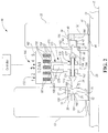
- FIG. 2 is a view similar to the view of FIG. 1 but showing a coast plunger rather than the forward plunger of FIG. 1 ;
- FIG. 3 is an end schematic view of a subassembly of the assembly of FIGS. 1 and 2 and showing forward and reverse or coast locking members in their uncoupling positions which corresponds to the device being in its full “off” position;
- FIG. 4 is a view similar to the view of FIG. 1 with a translater structure of the device in an intermediate axial position between, its full “off” position and a full “on” position;
- FIG. 5 is a view similar to the view of FIG. 4 but showing the coast plunger and not the forward plunger of FIG. 4 ;
- FIG. 6 is a view similar to the view of FIG. 3 and showing a forward locking member in its coupling position and a reverse or coast locking member in its uncoupling position which corresponds to the device being in its intermediate axial position;
- FIG. 7 is a view similar to the views of FIGS. 1 and 4 with the translater structure of the device in its full “on” axial position;
- FIG. 8 is a view similar to the view of FIG. 7 but showing the coast plunger and not the forward plunger of FIG. 7 ;
- FIG. 9 is a view similar to the views of FIGS. 3 and 6 showing the forward and reverse locking members in their coupling positions which corresponds to the device being in its full “on” position.
- FIGS. 1, 2, 4, 5, 7 and 8 An overrunning, non-friction, radial coupling and control assembly constructed in accordance with at least one embodiment of the present invention is generally indicated at 10 in FIGS. 1, 2, 4, 5, 7 and 8 .
- the assembly 10 preferably includes one or more radial, pawl-type clutch assemblies having bearing support.
- the assembly 10 includes a first pair of coupling members 12 and 13 .
- the member 12 is a pocket plate and the member 13 comprises a notch plate which is typically integrated with a powdered metal gear (not shown) which may be mounted for rotation with a shaft (also not shown).
- the pocket plate has pockets 16 and the notch plate has notches 17 .
- the members 12 and 13 are supported for rotation relative to one another about a common rotational axis 15 of an output shaft 19 .
- the member 13 is supported for rotation on the shaft 19 by bearing 21 .
- the coupling member 12 is splined to the output shaft 19 via splines 25 for rotation therewith.
- First locking members or pawls 23 (both forward and reverse) float freely in their pockets 16 and selectively mechanically couple the first pair of members 12 and 13 together upon engaging notches 17 to prevent relative rotation of the first pair of members 12 and 13 with respect to each other in at least one direction about the axis 15 .
- the assembly 10 also includes a second pair of coupling members 32 and 33 supported for rotation relative to one another about the common rotational axis 15 and second locking members or pawls 43 which float freely in their pockets 36 for selectively mechanically coupling the second pair of members 32 and 33 together to prevent relative rotation of the second pair of members 32 and 33 with respect to each other in at least one direction about the axis 15 .
- a powdered metal second gear (not shown) is typically integrally formed with the member 33 and is mounted for rotation with the shaft (not shown).
- the member 33 is supported for rotation on the shaft 19 by bearings 41 .
- the coupling member 32 is splined to the output shaft 19 via splines 45 for rotation therewith.
- the inner plate-like members 12 and 32 have outer peripheral surfaces 18 and 38 , respectively.
- the outer plate-like members 13 and 33 have inner peripheral surfaces 20 and 40 adjacent the outer peripheral surface 18 and 38 , respectively, in radially inner and radially outer relationship.
- Each of the members 12 and 32 includes the pockets 16 and 36 , respectively, angularly spaced about the axis 15 .
- Each of the pockets 16 and 36 has a closed end 22 and 42 , respectively, and an open end located axially opposite its closed end 22 or 42 .
- Each of the pawls 23 and 43 is located in its respective pocket 16 or 36 and is supported to pivot toward the inner peripheral surface 20 or 40 of its member 13 or 33 .
- the pawls 23 and 43 are retained within their respective pockets 16 and 36 by plate-like bushings or retainers 27 and 47 which are secured to their respective member 12 or 32 via locking or snap rings 28 and 48 .
- the retainers 27 and 47 partially cover the open ends of the pockets 16 and 36 , respectively.
- the inner and outer peripheral surfaces 20 and 18 define a first radial bearing interface adjacent the closed end 22 of each of the pockets 16 .
- the retainer 27 has a bearing surface which defines a bearing interface adjacent the open end of each of the pockets 16 .
- the inner and outer peripheral surfaces 40 and 38 define a second radial bearing interface adjacent the closed end 42 of each of the pockets 36 .
- the retainer 47 has a bearing surface which defines a bearing interface adjacent the open end of each of the pockets 36 .
- the assembly 10 includes sets of actuators, generally indicated at 51 , including biasing members, such as springs 50 .
- Each actuator 51 includes a sliding pin 52 having a head 53 received within an aperture formed in the lower surface of an end portion 54 of its respective pawl 23 .
- An opposite end portion 55 of each pawl 23 is configured to engage the notches 17 .
- Each of the biasing members 50 urges its respective pin 52 to move its respective pawl 23 toward the peripheral surface 20 of the member 13 .
- the assembly 10 also includes a 5-position linear stepper motor, generally indicated at 144 .
- the stepper motor 144 is typically controlled by a controller and includes the stator structure or subassembly 135 including at least one coil 166 (five shown) to create an electromagnetically switched magnetic field and to create a magnetic flux when the at least one coil 166 is energized.
- the stepper motor 144 further includes a magnetically-latching translator structure or actuator subassembly, generally indicated at 170 , including at least one bi-directionally movable connecting structure, such as a spring-biased forward rod or plunger, generally indicated at 172 in FIGS. 1, 4 and 7 .
- a similar spring-biased coast plunger is generally indicated as 172 ′ in FIGS. 2, 5 and 8 .
- the plunger 172 ′ is substantially identical to the plunger 172 . Consequently, the parts of plunger 172 ′ have the same reference number as the parts of the plunger 172 , but a prime designation.
- Each rod 172 (or 172 ′) includes a pair of spaced apart, funnel-shaped cams 174 and 176 , each of which has a contour surface 175 and 177 , respectively, to cause the first and second locking members 23 and 43 , respectively, to ride on their respective contour surfaces 175 and 177 to cause small-displacement, locking-member pivotal movement between coupling and uncoupling positions generally as shown in FIGS. 6 and 9 .
- the actuator subassembly 170 further includes a magnetic actuator, generally indicated at 171 , coupled to each rod 172 (or 172 ′) and mounted for controlled reciprocating movement along the rotational axis 15 relative to the first and second pairs of coupling members 12 and 13 , and 32 and 33 , respectively, between a first extended position (corresponds to position #1) which corresponds to a first mode of the first pair of coupling members 12 and 13 and a second extended position (corresponds to position #5) which corresponds to a second mode of the second pair of coupling members 32 and 33 .
- the cam 174 actuates the first locking member 23 in its extended position, so that the first locking member 23 couples the first pair of coupling members 12 and 13 for rotation with each other in at least one direction about the rotational axis 15 .
- Position #3 is a neutral position in which both the forward and reverse or coast rockers are in their “off” positions as shown in FIGS. 1-3 .
- Position #2 is an intermediate position between the neutral position of FIGS. 1-3 and position #1 of FIGS. 7-9 .
- the forward rockers are “on” and the coast rockers are “off” as shown in FIG. 6 .
- the forward rockers are “on” and the coast rockers are “on” as shown in FIG. 9 .
- the cam 176 actuates the second locking member 43 to couple the second pair of coupling members 32 and 33 for rotation with each other in at least one direction about the rotational axis 15 .
- the magnetic actuator 171 completes a path of the magnetic flux to magnetically latch in the extended positions (i.e. positions 1, 2, 4 and 5). A control force caused by the magnetic flux is applied to linearly move the magnetic actuator 171 between the extended positions along the rotational axis 15 .
- the magnetic actuator 171 preferably includes a permanent magnet source 178 sandwiched between a pair of annular field redirection rings 179 .
- the magnetic source 178 is preferably an annular, rare earth magnet which is axially magnetized.
- the electromechanical apparatus or motor 144 controls the operating mode of a pair of coupling apparatus, each of which has drive and driven members supported for rotation relative to one another about the common rotational axis 15 of the output shaft 19 .
- Each driven member may be the pocket plate 12 or 32 and the drive member may be the notch plate 13 or 33 .
- Each coupling apparatus or assembly may include two or more rockers or pawls 23 or 43 for selectively mechanically coupling the members of each coupling assembly together and change the operating mode of each coupling assembly.
- the rockers or pawls 23 and 43 are spaced at intervals about the axis 15 (i.e. FIGS. 3, 6 and 9 ).
- the actuator subassembly 170 is configured or adapted for coupling with the members or plates of both of the coupling apparatus to rotate therewith.
- the subassembly 170 is supported on the output shaft 19 for rotation relative to the coils 166 about the rotational axis 15 .
- the subassembly 170 typically includes two or more bi-directionally movable rods or shafts 172 .
- Each stem portion 180 or 182 of its funnel-shaped cam 174 and 176 respectively, is adapted to slide within an aperture 184 or 186 in its respective coupling member during the selective, small-displacement, locking member pivotal movement.
- a bushing 188 or 190 may slidably support the stem portions 180 or 182 , respectively, within the apertures 184 and 186 .
- the actuator 171 is operatively connected to the rods 172 for selective bi-directional shifting movement along the rotational axis 15 between a first position (i.e. position #1) of the actuator 171 which corresponds to a mode of the first coupling apparatus (plate 12 and plate 13 ) and a second position (i.e. position #5) of the actuator 171 which corresponds to a different mode of the coupling apparatus (plate 32 and plate 33 ).
- Two or more rods 172 may be spaced apart from one another as shown in FIGS. 3, 6 and 9 .
- the different modes may be locked and unlocked (i.e. free wheeling) modes and may lock in one or both directions of rotary movement about the axis 15 .
- a first magnetic control force is applied to the actuator 171 when the at least one coil 166 is energized to cause the actuator 171 to move between its first, second, third (i.e. neutral), fourth and fifth positions along the axis 15 .
- the actuator 171 includes a pair of spaced biasing spring members 192 and 194 for each rod 172 for exerting corresponding biasing forces on an I-shaped hub or support 196 in opposite directions along the axis 15 when the hub 196 moves between its first, second, third, fourth and fifth positions along the axis 15 .
- the hub 196 has holes for slideably receiving and supporting the connecting rods or shafts 172 . When the support 196 moves, it pushes/pulls its respective springs 192 and 194 between opposite faces of the support 196 and cylindrical portions of the funnel-shaped cams 174 and 176 .
- the hub 196 rotates with the shaft 19 about the rotational axis 15 .
- the hub 196 slideably supports interconnecting shaft portions of the shafts 172 during corresponding shifting movement along the rotational axis 15 via bushings mounted within the holes in the hub 196 .
- the member may include spaced stops to define the extended positions of the actuator 171 .
- the actuator 171 also preferably includes a set of spaced guide pins (not shown) sandwiched between inner surface of the member 12 and an outer surface of the hub 196 and extending along the rotational axis 15 .
- the inner surface and the outer surface may have V-shaped grooves or notches (not shown) formed therein to hold the guide pins.
- the hub 196 slides on the guide pins during shifting movement of the hub 196 along the rotational axis 15 .
- the guide pins pilot the hub 196 on the member 12 .
- the hub 196 may also distribute oil to the guide pins.
- the stator subassembly 135 includes a ferromagnetic housing 167 having spaced apart fingers 168 and the electromagnetically inductive coils 166 housed between adjacent fingers 168 .
- the actuator 171 is an annular part having the magnetic annular ring 178 sandwiched between the pair of ferromagnetic backing rings 179 .
- the magnetic control forces magnetically bias the fingers 168 and their corresponding backing rings 179 into alignment upon coil energization. These forces latch the actuator 171 in the two “on” or extended positions, two “intermediate” positions and the “off” or neutral position.
- the rings 179 are acted upon by the stator subassembly 135 to move the actuator 171 .
- the stator 24,28 cross section is a three iron tooth 72, two slot/coil 26 structure with the slot openings facing, across a radial air gap, the moving element or translator.
- the translator structure includes a single, axially-magnetized, rare earth PM ring 78 sandwiched between two iron field redirection rings 80.
- the sizing of the various components can be estimated from the scaling, given in meters, on the x and y axes.
- the magnetic field lines have been determined by a commercial magnetic finite element analysis (MFEA) software package.
- MFEA magnetic finite element analysis
- the solution shown in FIG. 13 is for the case of no coil current in the stator windings, and a translator axial position somewhat past, to the right of, the “neutral” or center position.
- the magnetic field lines, due to the translator magnet ring 78 alone, are seen to “flow” in closed paths with the majority of the lines flowing in a stator iron-air gap-translator iron/magnet circular path.
- the magnet axial magnetization is stipulated to be to the right, in the plus x-direction, and therefore the direction or polarity of the magnetic lines of force closed “flow” path, due to the magnet alone, would be a counter clockwise circulation.
- the polarity direction of the circulating magnetic lines of force due to an electric current is given by the “right hand rule.” If the thumb of one's right hand is made to point in the direction of the current flow in a wire, or a coil of wires, with the fingers encircling the cross section of the wire or the coil, the magnetic field lines or flux lines also encircle the wire or coil cross section and have a circulating direction in the same direction as the curling fingers.
- FIG. 16 the magnetic lines due the current in the left side coil alone then encircle this coil in the counter clockwise direction, while the magnetic lines due to the current in the right side coil encircle this coil in the clockwise direction.
- the net or total production of magnetic field lines, as shown in FIG. 16 is due to all three magnetic sources, the current in both coils and the translator magnet, so obviously there are regions in the machine structure where the individual sources of magnetic excitation enforce and add with each other and there are regions in the machine structure where the individual sources of magnetic excitation buck or subtract from each other. Since the coil current is reversible (plus or minus) the dual source enforcement and bucking regions within the machine structure and, most importantly, within the machine air gap, can be removed with respect to each other. This is the basis of the controllable/reversible direction linear motor disclosed herein.
- a slide show set of solutions for the total magnetic field lines within the linear motor structure with the same coil current drive as in the case shown in FIG. 16, as a function of the axial position of the translator, similar to that given for the previous case of magnet excitation alone, show that for the level of coil current assumed the net force on the translator structure is always to the left, no matter the assumed value of the translator position.
- FIGS. 18 and 19A respectively of the above-noted published application.
- the polarity of the coil currents for the case of FIGS. 18 and 19A are simply reversed from that of the case shown in FIGS. 16 and 17A, the translator position is the same as in the case of FIGS. 16 and 17A. In this case, coil current drives in the direction of the magnet latching force, when the translator position has moved to the left of the center position.
- Each embodiment of a drive system or powertrain constructed in accordance with the invention may utilize a main controller or electronic control unit (not shown) and one or more controllers as shown by the controllers in FIGS. 1 and 14.
- the controllers are preferably controlled by the control unit.
- control unit provides and regulates the power to drive the linear motor through one or more controllers.
- controllers typically has a microcontroller (i.e. MCU) including circuitry.
- MCU microcontroller
- Each controller typically receives command signals from the remote electronic control unit over or through a vehicle-based bus.
- control logic used by the control unit and/or the controller is implemented primarily in software executed by a microprocessor-based controller or the microcontroller (i.e. MCU).
- the control logic may be implemented in software, hardware, or a combination of software and hardware depending upon the particular application.
- the control logic is preferably provided in a computer-readable storage medium having stored data representing instructions executed by a computer.
- the computer-readable storage medium or media may be any of a number of known physical devices which utilize electric, magnetic, and/or optical devices to temporarily or persistently store executable instructions and associated calibration information, operating variables, and the like.
- the control unit and the controller are connected via a vehicle bus such as a local interconnect network (LIN or CAN) line or bus capable of two-way communications.
- LIN is one of many possible in-vehicle local area network (LAN) communications protocols.
- a power line and a ground line may be provided between the control unit and the controller.
- Each controller typically includes a transceiver interface within the MCU, a microprocessor and its control logic within the MCU, and a motor drive or driver, and an electrical power source.
- Each controller may be integrated or physically coupled within the housing, while the control unit is provided some distance away from the housing.
- the MCU of the motor controller typically includes a memory and may be configured as a conventional micro-computer including a CPU, a ROM, a RAM and the like or as a hardwired logic circuit.
- Sequenced Shifting (OFF, FWD, Coast) is described above in at least one embodiment of the present invention.
- the forward clutch is synced such that the forward rocker is in an over run state targeting 10 to 50 RPM
- the e-motor(s) then land on the rocker locking and transmitting torque in the forward direction.
- a 0-0 to a 1-0 to a 1-1 shift as opposed to a 0-0 to a 1-1 shift is better shift quality.
- the impact and NVH of a sequenced shift is negligible.
- a sequenced shift is more forgiving when syncing.
- a 0-0 to a 1-1 state is the same shift a dog-clutch executes and historically can be challenging due to the condition where the races of the clutch have to be synced (in a position) in order to be turned ON.
- Position 4 and 5 on the second clutch is the same as 2 and 1 on the first clutch.
- a 4-position device is described by Table 2.
Landscapes
- Engineering & Computer Science (AREA)
- General Engineering & Computer Science (AREA)
- Mechanical Engineering (AREA)
- Physics & Mathematics (AREA)
- Electromagnetism (AREA)
- Mechanical Operated Clutches (AREA)
- Transmission Devices (AREA)
- Reciprocating, Oscillating Or Vibrating Motors (AREA)
- Linear Motors (AREA)
- Dynamo-Electric Clutches, Dynamo-Electric Brakes (AREA)
Abstract
Description
| TABLE 1 | ||||
| |
1st |
1st |
2nd |
2nd Coast |
| 1 | X | X | ||
| 2 | |
|||
| 3 | ||||
| 4 | X | |||
| 5 | X | X | ||
| TABLE 2 | ||||
| |
1st |
1st |
2nd |
2nd Coast |
| 1 | X | X | ||
| 2 | |
|||
| 3 | ||||
| 4 | X | X | ||
Claims (20)
Priority Applications (1)
| Application Number | Priority Date | Filing Date | Title |
|---|---|---|---|
| US15/890,415 US10590999B2 (en) | 2017-06-01 | 2018-02-07 | Overrunning, non-friction, radial coupling and control assembly and switchable linear actuator device for use in the assembly |
Applications Claiming Priority (2)
| Application Number | Priority Date | Filing Date | Title |
|---|---|---|---|
| US201762513567P | 2017-06-01 | 2017-06-01 | |
| US15/890,415 US10590999B2 (en) | 2017-06-01 | 2018-02-07 | Overrunning, non-friction, radial coupling and control assembly and switchable linear actuator device for use in the assembly |
Publications (2)
| Publication Number | Publication Date |
|---|---|
| US20180347642A1 US20180347642A1 (en) | 2018-12-06 |
| US10590999B2 true US10590999B2 (en) | 2020-03-17 |
Family
ID=64456485
Family Applications (1)
| Application Number | Title | Priority Date | Filing Date |
|---|---|---|---|
| US15/890,415 Active 2038-08-26 US10590999B2 (en) | 2017-06-01 | 2018-02-07 | Overrunning, non-friction, radial coupling and control assembly and switchable linear actuator device for use in the assembly |
Country Status (5)
| Country | Link |
|---|---|
| US (1) | US10590999B2 (en) |
| JP (1) | JP2020521920A (en) |
| CN (1) | CN111094781B (en) |
| DE (1) | DE112018002826B4 (en) |
| WO (1) | WO2018222425A2 (en) |
Cited By (2)
| Publication number | Priority date | Publication date | Assignee | Title |
|---|---|---|---|---|
| US11614130B2 (en) | 2021-01-26 | 2023-03-28 | Means Industries, Inc. | Dynamic controllable dog clutch |
| US11692596B2 (en) | 2020-09-25 | 2023-07-04 | Means Industries, Inc. | Axially oriented linear actuator including single stator coil, and clutch assembly having the actuator |
Families Citing this family (12)
| Publication number | Priority date | Publication date | Assignee | Title |
|---|---|---|---|---|
| US10533618B2 (en) | 2013-09-26 | 2020-01-14 | Means Industries, Inc. | Overrunning, non-friction coupling and control assembly, engageable coupling assembly and locking member for use in the assemblies |
| US10619681B2 (en) * | 2014-09-16 | 2020-04-14 | Means Industries, Inc. | Overrunning, non-friction coupling and control assemblies and switchable linear actuator device and reciprocating electromechanical apparatus for use therein |
| US11035423B2 (en) | 2017-02-02 | 2021-06-15 | Means Industries, Inc. | Non-friction coupling and control assembly, engageable coupling assembly and locking member for use in the assemblies |
| EP3861226A4 (en) | 2018-10-04 | 2022-06-29 | Means Industries, Inc. | Coupling and control assembly having an internal latching mechanism |
| DE102018127155A1 (en) * | 2018-10-31 | 2020-04-30 | Bayerische Motoren Werke Aktiengesellschaft | Coupling assembly for a motor vehicle drive train and motor vehicle drive train |
| US11105380B2 (en) * | 2019-07-23 | 2021-08-31 | Ford Global Technologies, Llc | Wheel end disconnect system and method |
| US11894187B2 (en) | 2019-08-22 | 2024-02-06 | Husco Automotive Holdings Llc | Systems and methods for multi-stable solenoid |
| US11874142B2 (en) * | 2020-03-31 | 2024-01-16 | Means Industries, Inc. | Coupling and control assembly including a position sensor |
| US11542992B2 (en) * | 2020-03-31 | 2023-01-03 | Means Industries, Inc. | Coupling and control assembly including a non-contact, linear inductive position sensor |
| DE102021104228A1 (en) | 2020-03-31 | 2021-09-30 | Means Industries, Inc. | Coupling and control arrangement with a non-contact, linear inductive position sensor |
| US20220106991A1 (en) * | 2020-10-06 | 2022-04-07 | Means Industries, Inc. | Bearing Assembly for Translator of Linear Actuator of Clutch Assembly |
| DE102022001398A1 (en) * | 2022-04-23 | 2023-10-26 | Borg Warner Inc. | Pawl freewheel |
Citations (90)
| Publication number | Priority date | Publication date | Assignee | Title |
|---|---|---|---|---|
| US4050560A (en) | 1975-02-19 | 1977-09-27 | Stal-Laval Turbin Ab | Fluid pressure actuated clutch for starting multi-stage turbine |
| US4340133A (en) | 1979-05-23 | 1982-07-20 | Zahnradfabrik Friedrichshafen Ag | Device for sensing the engagement position of a clutch |
| US5052534A (en) | 1990-10-30 | 1991-10-01 | Dana Corporation | Electromagnetic synchronizing and shifting clutch |
| US5070978A (en) | 1990-04-19 | 1991-12-10 | Pires Paul B | One way drive device |
| US5206573A (en) | 1991-12-06 | 1993-04-27 | Mccleer Arthur P | Starting control circuit |
| US5231265A (en) | 1990-09-28 | 1993-07-27 | Balance Dynamics Corporation | Method and apparatus for the transfer of electrical power to a balancer |
| US5342258A (en) | 1991-08-16 | 1994-08-30 | Motion Sciences Inc. | Combinational incrementally variable transmissions and other gearing arrangements allowing maximum kinematic degrees of freedom |
| US5362293A (en) | 1992-12-14 | 1994-11-08 | E. I. Du Pont De Nemours And Company | Drive clutch for a centrifuge rotor |
| US5387854A (en) | 1992-09-02 | 1995-02-07 | Electric Power Research Institute, Inc. | Method of torque notch minimization for quasi square wave back EMF permanent magnet synchronous machines with voltage source drive |
| US5394321A (en) | 1992-09-02 | 1995-02-28 | Electric Power Research Institute, Inc. | Quasi square-wave back-EMF permanent magnet AC machines with five or more phases |
| US5597057A (en) | 1993-10-26 | 1997-01-28 | Brenco, Inc. | One-way clutch apparatus |
| US5638929A (en) | 1995-04-06 | 1997-06-17 | Hyundai Motor Company, Ltd. | Controllable one-way clutch for a vehicle |
| US5678668A (en) | 1996-08-26 | 1997-10-21 | Brenco, Incorporated | One-way overrunning clutch mechanism |
| US5802915A (en) * | 1996-05-23 | 1998-09-08 | Eaton Corporation | Transmission shifting mechanism with ball ramp actuator |
| US5846257A (en) | 1997-08-15 | 1998-12-08 | Nexus Medical System, Inc. Llc | Pressure sensor for a surgical system |
| US5918715A (en) | 1997-06-09 | 1999-07-06 | Means Industries, Inc. | Overrunning planar clutch assembly |
| US5924510A (en) | 1996-06-12 | 1999-07-20 | Ntn Corporation | Rotation transmission device |
| US5927455A (en) | 1997-07-21 | 1999-07-27 | Warn Industries | Overrunning pawl clutch |
| US6065576A (en) | 1998-03-20 | 2000-05-23 | Means Industries, Inc. | Strut for planar one-way clutch |
| US6075302A (en) | 1997-10-20 | 2000-06-13 | Mccleer; Patrick J. | Brushless heteropolar inductor machine |
| US6193038B1 (en) | 1999-08-18 | 2001-02-27 | Means Industries, Inc. | One-way clutch and method for making same |
| US6244965B1 (en) | 1997-04-28 | 2001-06-12 | Means Industries, Inc. | Controllable overrunning coupling |
| US6290044B1 (en) | 2000-04-03 | 2001-09-18 | General Motors Corporation | Selectable one-way clutch assembly |
| US6328670B1 (en) | 1998-04-28 | 2001-12-11 | Hitachi, Ltd. | Power transmission apparatus for an automobile |
| US6503167B1 (en) | 2000-09-28 | 2003-01-07 | Spicer Technology, Inc. | Externally actuated locking differential assembly |
| US20030102196A1 (en) | 2001-12-05 | 2003-06-05 | Aerotech Engineering & Research Corporation | Bidirectional linear motor |
| US20040110594A1 (en) | 2002-12-04 | 2004-06-10 | Ntn Corporation | Roller clutch assembly |
| US6814201B2 (en) | 2003-02-13 | 2004-11-09 | Borgwarner, Inc. | Bi-directional axially applied pawl clutch assembly |
| US6846257B2 (en) | 2002-12-11 | 2005-01-25 | Ntn Corporation | Series drive clutch |
| US6953409B2 (en) | 2003-12-19 | 2005-10-11 | General Motors Corporation | Two-mode, compound-split, hybrid electro-mechanical transmission having four fixed ratios |
| US6982502B1 (en) | 2003-09-26 | 2006-01-03 | The United States Of America As Represented By The Secretary Of The Navy | Hybrid electric linear actuator |
| US20060021836A1 (en) | 2004-07-27 | 2006-02-02 | John Kimes | Overrunning clutch |
| US20060138777A1 (en) | 2003-06-25 | 2006-06-29 | Peter Hofbauer | Ring generator |
| US7093512B2 (en) | 2000-03-10 | 2006-08-22 | Hitachi, Ltd. | Automatic transmission, dynamo-electric machine, and car |
| US20060185957A1 (en) | 2004-07-27 | 2006-08-24 | Kimes John W | Dual-mode one-way torque transmitting device |
| US20060252589A1 (en) | 2005-01-20 | 2006-11-09 | Tay Armin S | Adjuster systems for continuous variable transmissions |
| US20060278487A1 (en) | 2005-06-09 | 2006-12-14 | Means Industries, Inc. | Overrunning radial coupling assembly and method for controlling the engagement of inner and outer members of the assembly |
| US7153228B2 (en) | 2002-12-25 | 2006-12-26 | Sanden Corporation | Power transmission |
| US20070056825A1 (en) | 2005-09-14 | 2007-03-15 | Means Industries, Inc. | Overrunning coupling assembly including clustered pawls and method for controlling the engagement of planar members |
| US7198587B2 (en) | 2003-12-16 | 2007-04-03 | General Motors Corporation | Transmission with selectable braking one-way clutch |
| US7223198B2 (en) | 2004-07-27 | 2007-05-29 | Ford Global Technologies, Llc | Automatic transmission carrier assembly including an overrunning brake |
| US7256510B2 (en) | 2005-12-23 | 2007-08-14 | General Motors Corportion | Hybrid electro-mechanical transmission with single motor/generator and method of control |
| US7258214B2 (en) | 2005-06-09 | 2007-08-21 | Means Industries, Inc. | Overrunning coupling assembly and method for controlling the engagement of planar members |
| US7275628B2 (en) | 2005-06-09 | 2007-10-02 | Means Industries Inc. | Overrunning coupling assembly having improved shift feel and/or noise reduction |
| US20070278061A1 (en) | 2006-05-31 | 2007-12-06 | Gm Global Technology Operations, Inc. | Selectable One-Way Rocker Clutch |
| US20080110715A1 (en) | 2006-11-13 | 2008-05-15 | Means Industries, Inc. | Fluid actuated overrunning coupling assembly |
| US20080169166A1 (en) | 2007-01-12 | 2008-07-17 | Gm Global Technology Operations, Inc. | Rocker Clutch Assembly |
| US20080169165A1 (en) | 2007-01-12 | 2008-07-17 | Gm Global Technology Operations, Inc. | Selectable One-Way Clutch with Symmetrical Struts |
| US20080185253A1 (en) | 2007-02-06 | 2008-08-07 | Kimes John W | Selectively controlled rocker one-way clutch |
| US20080223681A1 (en) | 2007-03-13 | 2008-09-18 | Stevenson Paul D | Selectable one-way clutch |
| US7464801B2 (en) | 2006-01-17 | 2008-12-16 | Gm Global Technology Operations, Inc. | Selectable one-way clutch |
| US7491151B2 (en) | 2005-10-31 | 2009-02-17 | Gm Global Technology Operations, Inc. | Selectable one-way clutch control |
| US20090084653A1 (en) | 2007-09-28 | 2009-04-02 | Holmes Alan G | Electrically Variable Transmission with an Axially-Moveable Selectable One-Way Clutch Assembly |
| US20090098968A1 (en) | 2007-10-11 | 2009-04-16 | Gm Global Technology Operations, Inc. | Hybrid Powertrain With Single Electric Motor Integrated Within Automatic Transmission |
| US20090098970A1 (en) | 2007-10-12 | 2009-04-16 | Means Industries, Inc. | High-Efficiency Vehicular Transmission |
| US20090127059A1 (en) | 2006-01-25 | 2009-05-21 | Getrag Innovations Gmbh | Clutch arrangement for motor vehicle transmission and method for engaging and disengaging a gearspeed |
| US20090133981A1 (en) | 2005-08-27 | 2009-05-28 | Deere & Company | Gear Shifting Point for the Establishment of a Connection, Fixed Against Rotation, Between a Gear and a Shaft |
| US20090142207A1 (en) | 2007-11-30 | 2009-06-04 | Stellarton Technologies Inc. | Bottom hole hollow core electric submersible pumping system |
| US20090159391A1 (en) | 2007-12-19 | 2009-06-25 | Means Industries, Inc. | Overrunning Coupling Assembly |
| US20090194381A1 (en) | 2008-02-04 | 2009-08-06 | Gm Global Technology Operations, Inc. | Method and apparatus for controlling a selectable one-way clutch in an electro-mechanical transmission |
| US20090211863A1 (en) | 2008-02-21 | 2009-08-27 | Means Industries, Inc. | Controllable Overrunning Coupling Assembly |
| US20090255773A1 (en) | 2006-10-26 | 2009-10-15 | Getrag Getriebe- Und Zahnradfabrik Hermann Hagenmeyer Gmbh & Cie Kg | Actuator arrangement for a motor vehicle clutch |
| US20100044141A1 (en) | 2008-08-25 | 2010-02-25 | Ford Global Technologies, Inc. | Planetary Transmission Having Common Carrier for Generating Six Forward and Two Reverse Drive Ratios |
| US20100071497A1 (en) | 2006-10-19 | 2010-03-25 | Zf Friedrichshafen Ag | Transmission device having at least one shift element which can be actuated by means of an actuator arrangement which has at least one electrical component |
| US7690455B2 (en) | 2003-06-30 | 2010-04-06 | Toyota Jidosha Kabushiki Kaisha | Hybrid drive device and automobile mounted with device |
| US7695387B2 (en) | 2007-06-14 | 2010-04-13 | Toyota Jidosha Kabushiki Kaisha | Power output apparatus and hybrid vehicle equipped with power output apparatus |
| US20100119389A1 (en) | 2008-11-07 | 2010-05-13 | Robert Lazebnik | Modular, brushless motors and applications thereof |
| US20100200358A1 (en) | 2009-02-06 | 2010-08-12 | Means Industries, Inc. | Overrunning coupling and control assembly including apparatus having a latching mechanism |
| US20100230226A1 (en) | 2009-03-13 | 2010-09-16 | Means Industries, Inc. | Overrunning one-way clutch or coupling assembly |
| US7806795B2 (en) | 2007-06-22 | 2010-10-05 | Toyota Jidosha Kabushiki Kaisha | Power output apparatus and hybrid vehicle with power output apparatus |
| US20100252384A1 (en) | 2009-04-01 | 2010-10-07 | Means Industries, Inc. | Controllable coupling assembly and overrunning coupling and control assembly utilizing same |
| US7898121B2 (en) * | 2005-09-21 | 2011-03-01 | Ricardo Uk Ltd | Linear actuator |
| US20110140451A1 (en) | 2009-12-16 | 2011-06-16 | Clear Path Energy, Llc | Axial Gap Rotating Electrical Machine |
| US20110177900A1 (en) | 2010-01-15 | 2011-07-21 | Means Industries, Inc. | Hybrid electric vehicle drive system and control system for controlling a hybrid electric vehicle drive system |
| US20110215575A1 (en) | 2010-03-08 | 2011-09-08 | Ecomotors International, Inc. | Electrical Generator |
| US20110233026A1 (en) | 2010-03-26 | 2011-09-29 | Means Industries, Inc. | Overrunning coupling and control assembly including an electromechanical actuator subassembly |
| US20120149518A1 (en) | 2010-12-10 | 2012-06-14 | Means Industries, Inc. | Vehicle drive system including a transmission |
| US20130256078A1 (en) | 2007-10-12 | 2013-10-03 | Means Industries, Inc. | Electromechanically actuated coupling and control assembly |
| US20130277164A1 (en) | 2012-04-18 | 2013-10-24 | Means Industries, Inc. | Coupling and control assembly |
| US20140100071A1 (en) | 2012-10-04 | 2014-04-10 | Means Industries, Inc. | Vehicle drive system including a transmission |
| US8813929B2 (en) | 2010-12-10 | 2014-08-26 | Means Industries, Inc. | Controllable coupling assembly |
| US20140291100A1 (en) | 2013-04-02 | 2014-10-02 | Warner Electric Technology Llc | Electromagnetic actuator for a bi-directional clutch |
| US20150000442A1 (en) | 2010-12-10 | 2015-01-01 | Means Industries, Inc. | Electronic, high-efficiency vehicular transmission, overrunning, non-friction coupling and control assembly and switchable linear actuator device for use therein |
| US20150014116A1 (en) | 2010-12-10 | 2015-01-15 | Means Industries, Inc. | Device and apparatus for controlling the operating mode of a coupling assembly, coupling and control assembly and electric motor disconnect and pass through assemblies |
| US20150034448A1 (en) | 2012-03-14 | 2015-02-05 | Denso Corporation | Electromagnetic clutch |
| US9188172B2 (en) | 2013-01-10 | 2015-11-17 | Means Industries, Inc. | Compact overrunning coupling and control assembly having reduced part count and manufacturing complexity |
| US9186977B2 (en) | 2011-08-26 | 2015-11-17 | Means Industries, Inc. | Drive system including a transmission for a hybrid electric vehicle |
| US9303699B2 (en) | 2010-12-10 | 2016-04-05 | Means Industries, Inc. | Electromechanical assembly to control the operating mode of a coupling apparatus |
| US9441708B2 (en) | 2010-12-10 | 2016-09-13 | Means Industries, Inc. | High-efficiency drive system including a transmission for a hybrid electric vehicle |
| US20160290426A1 (en) | 2013-11-13 | 2016-10-06 | Schaeffler Technologies AG & Co. KG | Clutch assembly for coupling an internal combustion engine to a drive train of a motor vehicle and method for dampening torsional vibrations in a drive train of a motor vehicle |
Family Cites Families (6)
| Publication number | Priority date | Publication date | Assignee | Title |
|---|---|---|---|---|
| DE19947405A1 (en) | 1999-10-01 | 2001-04-05 | Mannesmann Sachs Ag | Vehicle automatic transmission gearbox includes linear electrical stepper motor to operate synch unit |
| CN2511828Y (en) * | 2001-08-13 | 2002-09-18 | 蒋国祥 | Assembled overrunning clutch and automatic overrunning gearbox |
| JP4493932B2 (en) * | 2003-05-13 | 2010-06-30 | 東京エレクトロン株式会社 | Upper electrode and plasma processing apparatus |
| US7599778B2 (en) * | 2006-04-22 | 2009-10-06 | Juan Zak | Transmission with intelligent gear synchronization and shifting |
| CN101614253B (en) * | 2009-07-23 | 2010-12-08 | 东南大学 | Clutch for dual drive system |
| CN103403384B (en) * | 2011-02-14 | 2016-04-20 | 敏思工业公司 | For controlling the electromechanical assemblies of the operating mode of coupling equipment |
-
2018
- 2018-02-07 US US15/890,415 patent/US10590999B2/en active Active
- 2018-05-21 CN CN201880036673.9A patent/CN111094781B/en active Active
- 2018-05-21 DE DE112018002826.7T patent/DE112018002826B4/en active Active
- 2018-05-21 JP JP2019565831A patent/JP2020521920A/en active Pending
- 2018-05-21 WO PCT/US2018/033591 patent/WO2018222425A2/en active Application Filing
Patent Citations (101)
| Publication number | Priority date | Publication date | Assignee | Title |
|---|---|---|---|---|
| US4050560A (en) | 1975-02-19 | 1977-09-27 | Stal-Laval Turbin Ab | Fluid pressure actuated clutch for starting multi-stage turbine |
| US4340133A (en) | 1979-05-23 | 1982-07-20 | Zahnradfabrik Friedrichshafen Ag | Device for sensing the engagement position of a clutch |
| US5070978A (en) | 1990-04-19 | 1991-12-10 | Pires Paul B | One way drive device |
| US5453598A (en) | 1990-09-28 | 1995-09-26 | The Balance Dynamics Corporation | Apparatus for the transfer of electrical power to a balancer |
| US5231265A (en) | 1990-09-28 | 1993-07-27 | Balance Dynamics Corporation | Method and apparatus for the transfer of electrical power to a balancer |
| US5052534A (en) | 1990-10-30 | 1991-10-01 | Dana Corporation | Electromagnetic synchronizing and shifting clutch |
| US5342258A (en) | 1991-08-16 | 1994-08-30 | Motion Sciences Inc. | Combinational incrementally variable transmissions and other gearing arrangements allowing maximum kinematic degrees of freedom |
| US5206573A (en) | 1991-12-06 | 1993-04-27 | Mccleer Arthur P | Starting control circuit |
| US5387854A (en) | 1992-09-02 | 1995-02-07 | Electric Power Research Institute, Inc. | Method of torque notch minimization for quasi square wave back EMF permanent magnet synchronous machines with voltage source drive |
| US5394321A (en) | 1992-09-02 | 1995-02-28 | Electric Power Research Institute, Inc. | Quasi square-wave back-EMF permanent magnet AC machines with five or more phases |
| US5642009A (en) | 1992-09-02 | 1997-06-24 | Electric Power Research Institute, Inc. | Quasi square-wave back-EMF permanent magnet AC machines with five or more phases |
| US5362293A (en) | 1992-12-14 | 1994-11-08 | E. I. Du Pont De Nemours And Company | Drive clutch for a centrifuge rotor |
| US5597057A (en) | 1993-10-26 | 1997-01-28 | Brenco, Inc. | One-way clutch apparatus |
| US5638929A (en) | 1995-04-06 | 1997-06-17 | Hyundai Motor Company, Ltd. | Controllable one-way clutch for a vehicle |
| US5802915A (en) * | 1996-05-23 | 1998-09-08 | Eaton Corporation | Transmission shifting mechanism with ball ramp actuator |
| US5924510A (en) | 1996-06-12 | 1999-07-20 | Ntn Corporation | Rotation transmission device |
| US5678668A (en) | 1996-08-26 | 1997-10-21 | Brenco, Incorporated | One-way overrunning clutch mechanism |
| US6244965B1 (en) | 1997-04-28 | 2001-06-12 | Means Industries, Inc. | Controllable overrunning coupling |
| US5918715A (en) | 1997-06-09 | 1999-07-06 | Means Industries, Inc. | Overrunning planar clutch assembly |
| US5927455A (en) | 1997-07-21 | 1999-07-27 | Warn Industries | Overrunning pawl clutch |
| US5846257A (en) | 1997-08-15 | 1998-12-08 | Nexus Medical System, Inc. Llc | Pressure sensor for a surgical system |
| US6075302A (en) | 1997-10-20 | 2000-06-13 | Mccleer; Patrick J. | Brushless heteropolar inductor machine |
| US6065576A (en) | 1998-03-20 | 2000-05-23 | Means Industries, Inc. | Strut for planar one-way clutch |
| US6328670B1 (en) | 1998-04-28 | 2001-12-11 | Hitachi, Ltd. | Power transmission apparatus for an automobile |
| US6692405B2 (en) | 1998-04-28 | 2004-02-17 | Hitachi, Ltd. | Power transmission apparatus for an automobile |
| US6193038B1 (en) | 1999-08-18 | 2001-02-27 | Means Industries, Inc. | One-way clutch and method for making same |
| US7093512B2 (en) | 2000-03-10 | 2006-08-22 | Hitachi, Ltd. | Automatic transmission, dynamo-electric machine, and car |
| US6290044B1 (en) | 2000-04-03 | 2001-09-18 | General Motors Corporation | Selectable one-way clutch assembly |
| US6503167B1 (en) | 2000-09-28 | 2003-01-07 | Spicer Technology, Inc. | Externally actuated locking differential assembly |
| US20030102196A1 (en) | 2001-12-05 | 2003-06-05 | Aerotech Engineering & Research Corporation | Bidirectional linear motor |
| US20040110594A1 (en) | 2002-12-04 | 2004-06-10 | Ntn Corporation | Roller clutch assembly |
| US6846257B2 (en) | 2002-12-11 | 2005-01-25 | Ntn Corporation | Series drive clutch |
| US7153228B2 (en) | 2002-12-25 | 2006-12-26 | Sanden Corporation | Power transmission |
| US6814201B2 (en) | 2003-02-13 | 2004-11-09 | Borgwarner, Inc. | Bi-directional axially applied pawl clutch assembly |
| US20060138777A1 (en) | 2003-06-25 | 2006-06-29 | Peter Hofbauer | Ring generator |
| US7690455B2 (en) | 2003-06-30 | 2010-04-06 | Toyota Jidosha Kabushiki Kaisha | Hybrid drive device and automobile mounted with device |
| US6982502B1 (en) | 2003-09-26 | 2006-01-03 | The United States Of America As Represented By The Secretary Of The Navy | Hybrid electric linear actuator |
| US7198587B2 (en) | 2003-12-16 | 2007-04-03 | General Motors Corporation | Transmission with selectable braking one-way clutch |
| US6953409B2 (en) | 2003-12-19 | 2005-10-11 | General Motors Corporation | Two-mode, compound-split, hybrid electro-mechanical transmission having four fixed ratios |
| US7223198B2 (en) | 2004-07-27 | 2007-05-29 | Ford Global Technologies, Llc | Automatic transmission carrier assembly including an overrunning brake |
| US20060021836A1 (en) | 2004-07-27 | 2006-02-02 | John Kimes | Overrunning clutch |
| US20060185957A1 (en) | 2004-07-27 | 2006-08-24 | Kimes John W | Dual-mode one-way torque transmitting device |
| US20060252589A1 (en) | 2005-01-20 | 2006-11-09 | Tay Armin S | Adjuster systems for continuous variable transmissions |
| US20060278487A1 (en) | 2005-06-09 | 2006-12-14 | Means Industries, Inc. | Overrunning radial coupling assembly and method for controlling the engagement of inner and outer members of the assembly |
| US7258214B2 (en) | 2005-06-09 | 2007-08-21 | Means Industries, Inc. | Overrunning coupling assembly and method for controlling the engagement of planar members |
| US7275628B2 (en) | 2005-06-09 | 2007-10-02 | Means Industries Inc. | Overrunning coupling assembly having improved shift feel and/or noise reduction |
| US7484605B2 (en) | 2005-06-09 | 2009-02-03 | Means Industries, Inc. | Overrunning radial coupling assembly and method for controlling the engagement of inner and outer members of the assembly |
| US20090133981A1 (en) | 2005-08-27 | 2009-05-28 | Deere & Company | Gear Shifting Point for the Establishment of a Connection, Fixed Against Rotation, Between a Gear and a Shaft |
| US7344010B2 (en) | 2005-09-14 | 2008-03-18 | Means Industries, Inc. | Overrunning coupling assembly including clustered pawls and method for controlling the engagement of planar members |
| US20070056825A1 (en) | 2005-09-14 | 2007-03-15 | Means Industries, Inc. | Overrunning coupling assembly including clustered pawls and method for controlling the engagement of planar members |
| US7898121B2 (en) * | 2005-09-21 | 2011-03-01 | Ricardo Uk Ltd | Linear actuator |
| US7491151B2 (en) | 2005-10-31 | 2009-02-17 | Gm Global Technology Operations, Inc. | Selectable one-way clutch control |
| US7256510B2 (en) | 2005-12-23 | 2007-08-14 | General Motors Corportion | Hybrid electro-mechanical transmission with single motor/generator and method of control |
| US7464801B2 (en) | 2006-01-17 | 2008-12-16 | Gm Global Technology Operations, Inc. | Selectable one-way clutch |
| US20090127059A1 (en) | 2006-01-25 | 2009-05-21 | Getrag Innovations Gmbh | Clutch arrangement for motor vehicle transmission and method for engaging and disengaging a gearspeed |
| US7743678B2 (en) * | 2006-05-31 | 2010-06-29 | Gm Global Technology Operations, Inc. | Selectable one-way rocker clutch |
| US20070278061A1 (en) | 2006-05-31 | 2007-12-06 | Gm Global Technology Operations, Inc. | Selectable One-Way Rocker Clutch |
| US20100071497A1 (en) | 2006-10-19 | 2010-03-25 | Zf Friedrichshafen Ag | Transmission device having at least one shift element which can be actuated by means of an actuator arrangement which has at least one electrical component |
| US20090255773A1 (en) | 2006-10-26 | 2009-10-15 | Getrag Getriebe- Und Zahnradfabrik Hermann Hagenmeyer Gmbh & Cie Kg | Actuator arrangement for a motor vehicle clutch |
| US20080110715A1 (en) | 2006-11-13 | 2008-05-15 | Means Industries, Inc. | Fluid actuated overrunning coupling assembly |
| US20080169166A1 (en) | 2007-01-12 | 2008-07-17 | Gm Global Technology Operations, Inc. | Rocker Clutch Assembly |
| US20080169165A1 (en) | 2007-01-12 | 2008-07-17 | Gm Global Technology Operations, Inc. | Selectable One-Way Clutch with Symmetrical Struts |
| US20080185253A1 (en) | 2007-02-06 | 2008-08-07 | Kimes John W | Selectively controlled rocker one-way clutch |
| US8491439B2 (en) | 2007-02-06 | 2013-07-23 | Ford Global Technologies, Llc | Selectively controlled rocker one-way clutch |
| US20080223681A1 (en) | 2007-03-13 | 2008-09-18 | Stevenson Paul D | Selectable one-way clutch |
| US7695387B2 (en) | 2007-06-14 | 2010-04-13 | Toyota Jidosha Kabushiki Kaisha | Power output apparatus and hybrid vehicle equipped with power output apparatus |
| US7806795B2 (en) | 2007-06-22 | 2010-10-05 | Toyota Jidosha Kabushiki Kaisha | Power output apparatus and hybrid vehicle with power output apparatus |
| US20090084653A1 (en) | 2007-09-28 | 2009-04-02 | Holmes Alan G | Electrically Variable Transmission with an Axially-Moveable Selectable One-Way Clutch Assembly |
| US20090098968A1 (en) | 2007-10-11 | 2009-04-16 | Gm Global Technology Operations, Inc. | Hybrid Powertrain With Single Electric Motor Integrated Within Automatic Transmission |
| US20130256078A1 (en) | 2007-10-12 | 2013-10-03 | Means Industries, Inc. | Electromechanically actuated coupling and control assembly |
| US7942781B2 (en) | 2007-10-12 | 2011-05-17 | Means Industries, Inc. | High-efficiency vehicular transmission |
| US9109636B2 (en) | 2007-10-12 | 2015-08-18 | Means Industries, Inc. | Electromechanically actuated coupling and control assembly |
| US20090098970A1 (en) | 2007-10-12 | 2009-04-16 | Means Industries, Inc. | High-Efficiency Vehicular Transmission |
| US20090142207A1 (en) | 2007-11-30 | 2009-06-04 | Stellarton Technologies Inc. | Bottom hole hollow core electric submersible pumping system |
| US20090159391A1 (en) | 2007-12-19 | 2009-06-25 | Means Industries, Inc. | Overrunning Coupling Assembly |
| US20090194381A1 (en) | 2008-02-04 | 2009-08-06 | Gm Global Technology Operations, Inc. | Method and apparatus for controlling a selectable one-way clutch in an electro-mechanical transmission |
| US20090211863A1 (en) | 2008-02-21 | 2009-08-27 | Means Industries, Inc. | Controllable Overrunning Coupling Assembly |
| US20100044141A1 (en) | 2008-08-25 | 2010-02-25 | Ford Global Technologies, Inc. | Planetary Transmission Having Common Carrier for Generating Six Forward and Two Reverse Drive Ratios |
| US20100119389A1 (en) | 2008-11-07 | 2010-05-13 | Robert Lazebnik | Modular, brushless motors and applications thereof |
| US20100200358A1 (en) | 2009-02-06 | 2010-08-12 | Means Industries, Inc. | Overrunning coupling and control assembly including apparatus having a latching mechanism |
| US20100230226A1 (en) | 2009-03-13 | 2010-09-16 | Means Industries, Inc. | Overrunning one-way clutch or coupling assembly |
| US20100252384A1 (en) | 2009-04-01 | 2010-10-07 | Means Industries, Inc. | Controllable coupling assembly and overrunning coupling and control assembly utilizing same |
| US20110140451A1 (en) | 2009-12-16 | 2011-06-16 | Clear Path Energy, Llc | Axial Gap Rotating Electrical Machine |
| US20110177900A1 (en) | 2010-01-15 | 2011-07-21 | Means Industries, Inc. | Hybrid electric vehicle drive system and control system for controlling a hybrid electric vehicle drive system |
| US20110215575A1 (en) | 2010-03-08 | 2011-09-08 | Ecomotors International, Inc. | Electrical Generator |
| US20110233026A1 (en) | 2010-03-26 | 2011-09-29 | Means Industries, Inc. | Overrunning coupling and control assembly including an electromechanical actuator subassembly |
| US9441708B2 (en) | 2010-12-10 | 2016-09-13 | Means Industries, Inc. | High-efficiency drive system including a transmission for a hybrid electric vehicle |
| US9435387B2 (en) | 2010-12-10 | 2016-09-06 | Means Industries, Inc. | Device and apparatus for controlling the operating mode of a coupling assembly, coupling and control assembly and electric motor disconnect and pass through assemblies |
| US8813929B2 (en) | 2010-12-10 | 2014-08-26 | Means Industries, Inc. | Controllable coupling assembly |
| US9303699B2 (en) | 2010-12-10 | 2016-04-05 | Means Industries, Inc. | Electromechanical assembly to control the operating mode of a coupling apparatus |
| US8888637B2 (en) | 2010-12-10 | 2014-11-18 | Means Industries, Inc. | Vehicle drive system including a transmission |
| US20150000442A1 (en) | 2010-12-10 | 2015-01-01 | Means Industries, Inc. | Electronic, high-efficiency vehicular transmission, overrunning, non-friction coupling and control assembly and switchable linear actuator device for use therein |
| US20150014116A1 (en) | 2010-12-10 | 2015-01-15 | Means Industries, Inc. | Device and apparatus for controlling the operating mode of a coupling assembly, coupling and control assembly and electric motor disconnect and pass through assemblies |
| US20120149518A1 (en) | 2010-12-10 | 2012-06-14 | Means Industries, Inc. | Vehicle drive system including a transmission |
| US9186977B2 (en) | 2011-08-26 | 2015-11-17 | Means Industries, Inc. | Drive system including a transmission for a hybrid electric vehicle |
| US20150034448A1 (en) | 2012-03-14 | 2015-02-05 | Denso Corporation | Electromagnetic clutch |
| US20130277164A1 (en) | 2012-04-18 | 2013-10-24 | Means Industries, Inc. | Coupling and control assembly |
| US20140100071A1 (en) | 2012-10-04 | 2014-04-10 | Means Industries, Inc. | Vehicle drive system including a transmission |
| US9188172B2 (en) | 2013-01-10 | 2015-11-17 | Means Industries, Inc. | Compact overrunning coupling and control assembly having reduced part count and manufacturing complexity |
| US20140291100A1 (en) | 2013-04-02 | 2014-10-02 | Warner Electric Technology Llc | Electromagnetic actuator for a bi-directional clutch |
| US20160290426A1 (en) | 2013-11-13 | 2016-10-06 | Schaeffler Technologies AG & Co. KG | Clutch assembly for coupling an internal combustion engine to a drive train of a motor vehicle and method for dampening torsional vibrations in a drive train of a motor vehicle |
Non-Patent Citations (1)
| Title |
|---|
| International Searching Authority, International Search Report for International Application No. PCT/US2018/33591 dated Aug. 13, 2018. |
Cited By (2)
| Publication number | Priority date | Publication date | Assignee | Title |
|---|---|---|---|---|
| US11692596B2 (en) | 2020-09-25 | 2023-07-04 | Means Industries, Inc. | Axially oriented linear actuator including single stator coil, and clutch assembly having the actuator |
| US11614130B2 (en) | 2021-01-26 | 2023-03-28 | Means Industries, Inc. | Dynamic controllable dog clutch |
Also Published As
| Publication number | Publication date |
|---|---|
| CN111094781B (en) | 2021-09-07 |
| US20180347642A1 (en) | 2018-12-06 |
| DE112018002826B4 (en) | 2023-09-07 |
| JP2020521920A (en) | 2020-07-27 |
| WO2018222425A2 (en) | 2018-12-06 |
| CN111094781A (en) | 2020-05-01 |
| DE112018002826T5 (en) | 2020-02-13 |
| WO2018222425A3 (en) | 2020-04-02 |
Similar Documents
| Publication | Publication Date | Title |
|---|---|---|
| US10590999B2 (en) | Overrunning, non-friction, radial coupling and control assembly and switchable linear actuator device for use in the assembly | |
| US10619681B2 (en) | Overrunning, non-friction coupling and control assemblies and switchable linear actuator device and reciprocating electromechanical apparatus for use therein | |
| US20210301886A1 (en) | Non-Friction Coupling and Control Assembly, Engageable Coupling Assembly and Locking Member for Use in the Assemblies | |
| US10533618B2 (en) | Overrunning, non-friction coupling and control assembly, engageable coupling assembly and locking member for use in the assemblies | |
| US9435387B2 (en) | Device and apparatus for controlling the operating mode of a coupling assembly, coupling and control assembly and electric motor disconnect and pass through assemblies | |
| US9874252B2 (en) | Electronic, high-efficiency vehicular transmission, overrunning, non-friction coupling and control assembly and switchable linear actuator device for use therein | |
| US10677296B2 (en) | Electronic, high-efficiency vehicular transmission, overrunning, non-friction coupling and control assembly and switchable linear actuator device for use therein | |
| US9303699B2 (en) | Electromechanical assembly to control the operating mode of a coupling apparatus | |
| US8646587B2 (en) | Strut for a controllable one-way clutch | |
| US8813929B2 (en) | Controllable coupling assembly | |
| US9377061B2 (en) | Electromagnetic system for controlling the operating mode of an overrunning coupling assembly and overrunning coupling and control assembly including the system | |
| JP6021229B2 (en) | Electromechanical assembly that controls the operating mode of the coupling device | |
| US11286996B2 (en) | Electro-dynamic coupling and control assembly and switchable linear actuator device for use therein | |
| EP3577362B1 (en) | Reciprocating electromechanical apparatus | |
| EP3049686B1 (en) | Electronic, high-efficiency vehicular transmission, overrunning, non-friction coupling and control assembly and switchable linear actuator device for use therein | |
| EP3049685B1 (en) | Apparatus for controlling operating modes of a coupling assembly, and electric motor disconnect and pass through assemblies | |
| WO2020163686A1 (en) | Non-friction coupling and control assembly, engageable coupling assembly and locking member for use in the assemblies | |
| WO2015047938A1 (en) | Electromagnetic system for overrunning coupling assembly |
Legal Events
| Date | Code | Title | Description |
|---|---|---|---|
| AS | Assignment |
Owner name: MEANS INDUSTRIES, INC., MICHIGAN Free format text: ASSIGNMENT OF ASSIGNORS INTEREST;ASSIGNOR:KIMES, JOHN W.;REEL/FRAME:044851/0274 Effective date: 20180205 |
|
| FEPP | Fee payment procedure |
Free format text: ENTITY STATUS SET TO UNDISCOUNTED (ORIGINAL EVENT CODE: BIG.); ENTITY STATUS OF PATENT OWNER: LARGE ENTITY |
|
| STPP | Information on status: patent application and granting procedure in general |
Free format text: DOCKETED NEW CASE - READY FOR EXAMINATION |
|
| AS | Assignment |
Owner name: BANK OF AMERICA, N.A., AS ADMINISTRATIVE AGENT, IL Free format text: NOTICE OF GRANT OF SECURITY INTEREST IN PATENTS;ASSIGNOR:MEANS INDUSTRIES, INC.;REEL/FRAME:048478/0571 Effective date: 20190228 Owner name: BANK OF AMERICA, N.A., AS ADMINISTRATIVE AGENT, ILLINOIS Free format text: NOTICE OF GRANT OF SECURITY INTEREST IN PATENTS;ASSIGNOR:MEANS INDUSTRIES, INC.;REEL/FRAME:048478/0571 Effective date: 20190228 |
|
| STPP | Information on status: patent application and granting procedure in general |
Free format text: NON FINAL ACTION MAILED |
|
| STPP | Information on status: patent application and granting procedure in general |
Free format text: RESPONSE TO NON-FINAL OFFICE ACTION ENTERED AND FORWARDED TO EXAMINER |
|
| STPP | Information on status: patent application and granting procedure in general |
Free format text: NOTICE OF ALLOWANCE MAILED -- APPLICATION RECEIVED IN OFFICE OF PUBLICATIONS |
|
| STPP | Information on status: patent application and granting procedure in general |
Free format text: PUBLICATIONS -- ISSUE FEE PAYMENT VERIFIED |
|
| STCF | Information on status: patent grant |
Free format text: PATENTED CASE |
|
| MAFP | Maintenance fee payment |
Free format text: PAYMENT OF MAINTENANCE FEE, 4TH YEAR, LARGE ENTITY (ORIGINAL EVENT CODE: M1551); ENTITY STATUS OF PATENT OWNER: LARGE ENTITY Year of fee payment: 4 |