US10555865B2 - Torque control methods for an exoskeleton device - Google Patents
Torque control methods for an exoskeleton device Download PDFInfo
- Publication number
- US10555865B2 US10555865B2 US15/605,520 US201715605520A US10555865B2 US 10555865 B2 US10555865 B2 US 10555865B2 US 201715605520 A US201715605520 A US 201715605520A US 10555865 B2 US10555865 B2 US 10555865B2
- Authority
- US
- United States
- Prior art keywords
- torque
- rotational joint
- motor
- determining
- apply
- Prior art date
- Legal status (The legal status is an assumption and is not a legal conclusion. Google has not performed a legal analysis and makes no representation as to the accuracy of the status listed.)
- Active, expires
Links
Images


Classifications
-
- A—HUMAN NECESSITIES
- A61—MEDICAL OR VETERINARY SCIENCE; HYGIENE
- A61H—PHYSICAL THERAPY APPARATUS, e.g. DEVICES FOR LOCATING OR STIMULATING REFLEX POINTS IN THE BODY; ARTIFICIAL RESPIRATION; MASSAGE; BATHING DEVICES FOR SPECIAL THERAPEUTIC OR HYGIENIC PURPOSES OR SPECIFIC PARTS OF THE BODY
- A61H3/00—Appliances for aiding patients or disabled persons to walk about
-
- A—HUMAN NECESSITIES
- A61—MEDICAL OR VETERINARY SCIENCE; HYGIENE
- A61H—PHYSICAL THERAPY APPARATUS, e.g. DEVICES FOR LOCATING OR STIMULATING REFLEX POINTS IN THE BODY; ARTIFICIAL RESPIRATION; MASSAGE; BATHING DEVICES FOR SPECIAL THERAPEUTIC OR HYGIENIC PURPOSES OR SPECIFIC PARTS OF THE BODY
- A61H1/00—Apparatus for passive exercising; Vibrating apparatus ; Chiropractic devices, e.g. body impacting devices, external devices for briefly extending or aligning unbroken bones
- A61H1/02—Stretching or bending or torsioning apparatus for exercising
- A61H1/0237—Stretching or bending or torsioning apparatus for exercising for the lower limbs
- A61H1/024—Knee
-
- A—HUMAN NECESSITIES
- A61—MEDICAL OR VETERINARY SCIENCE; HYGIENE
- A61H—PHYSICAL THERAPY APPARATUS, e.g. DEVICES FOR LOCATING OR STIMULATING REFLEX POINTS IN THE BODY; ARTIFICIAL RESPIRATION; MASSAGE; BATHING DEVICES FOR SPECIAL THERAPEUTIC OR HYGIENIC PURPOSES OR SPECIFIC PARTS OF THE BODY
- A61H1/00—Apparatus for passive exercising; Vibrating apparatus ; Chiropractic devices, e.g. body impacting devices, external devices for briefly extending or aligning unbroken bones
- A61H1/02—Stretching or bending or torsioning apparatus for exercising
- A61H1/0237—Stretching or bending or torsioning apparatus for exercising for the lower limbs
- A61H1/0266—Foot
-
- F—MECHANICAL ENGINEERING; LIGHTING; HEATING; WEAPONS; BLASTING
- F16—ENGINEERING ELEMENTS AND UNITS; GENERAL MEASURES FOR PRODUCING AND MAINTAINING EFFECTIVE FUNCTIONING OF MACHINES OR INSTALLATIONS; THERMAL INSULATION IN GENERAL
- F16C—SHAFTS; FLEXIBLE SHAFTS; ELEMENTS OR CRANKSHAFT MECHANISMS; ROTARY BODIES OTHER THAN GEARING ELEMENTS; BEARINGS
- F16C1/00—Flexible shafts; Mechanical means for transmitting movement in a flexible sheathing
- F16C1/10—Means for transmitting linear movement in a flexible sheathing, e.g. "Bowden-mechanisms"
- F16C1/12—Arrangements for transmitting movement to or from the flexible member
-
- G—PHYSICS
- G05—CONTROLLING; REGULATING
- G05B—CONTROL OR REGULATING SYSTEMS IN GENERAL; FUNCTIONAL ELEMENTS OF SUCH SYSTEMS; MONITORING OR TESTING ARRANGEMENTS FOR SUCH SYSTEMS OR ELEMENTS
- G05B6/00—Internal feedback arrangements for obtaining particular characteristics, e.g. proportional, integral, differential
- G05B6/02—Internal feedback arrangements for obtaining particular characteristics, e.g. proportional, integral, differential electric
-
- G—PHYSICS
- G05—CONTROLLING; REGULATING
- G05D—SYSTEMS FOR CONTROLLING OR REGULATING NON-ELECTRIC VARIABLES
- G05D17/00—Control of torque; Control of mechanical power
- G05D17/02—Control of torque; Control of mechanical power characterised by the use of electric means
-
- A—HUMAN NECESSITIES
- A61—MEDICAL OR VETERINARY SCIENCE; HYGIENE
- A61H—PHYSICAL THERAPY APPARATUS, e.g. DEVICES FOR LOCATING OR STIMULATING REFLEX POINTS IN THE BODY; ARTIFICIAL RESPIRATION; MASSAGE; BATHING DEVICES FOR SPECIAL THERAPEUTIC OR HYGIENIC PURPOSES OR SPECIFIC PARTS OF THE BODY
- A61H3/00—Appliances for aiding patients or disabled persons to walk about
- A61H2003/007—Appliances for aiding patients or disabled persons to walk about secured to the patient, e.g. with belts
-
- A—HUMAN NECESSITIES
- A61—MEDICAL OR VETERINARY SCIENCE; HYGIENE
- A61H—PHYSICAL THERAPY APPARATUS, e.g. DEVICES FOR LOCATING OR STIMULATING REFLEX POINTS IN THE BODY; ARTIFICIAL RESPIRATION; MASSAGE; BATHING DEVICES FOR SPECIAL THERAPEUTIC OR HYGIENIC PURPOSES OR SPECIFIC PARTS OF THE BODY
- A61H2201/00—Characteristics of apparatus not provided for in the preceding codes
- A61H2201/01—Constructive details
- A61H2201/0165—Damping, vibration related features
-
- A—HUMAN NECESSITIES
- A61—MEDICAL OR VETERINARY SCIENCE; HYGIENE
- A61H—PHYSICAL THERAPY APPARATUS, e.g. DEVICES FOR LOCATING OR STIMULATING REFLEX POINTS IN THE BODY; ARTIFICIAL RESPIRATION; MASSAGE; BATHING DEVICES FOR SPECIAL THERAPEUTIC OR HYGIENIC PURPOSES OR SPECIFIC PARTS OF THE BODY
- A61H2201/00—Characteristics of apparatus not provided for in the preceding codes
- A61H2201/12—Driving means
- A61H2201/1207—Driving means with electric or magnetic drive
- A61H2201/1215—Rotary drive
- A61H2201/1223—Frequency controlled AC motor
-
- A—HUMAN NECESSITIES
- A61—MEDICAL OR VETERINARY SCIENCE; HYGIENE
- A61H—PHYSICAL THERAPY APPARATUS, e.g. DEVICES FOR LOCATING OR STIMULATING REFLEX POINTS IN THE BODY; ARTIFICIAL RESPIRATION; MASSAGE; BATHING DEVICES FOR SPECIAL THERAPEUTIC OR HYGIENIC PURPOSES OR SPECIFIC PARTS OF THE BODY
- A61H2201/00—Characteristics of apparatus not provided for in the preceding codes
- A61H2201/14—Special force transmission means, i.e. between the driving means and the interface with the user
- A61H2201/1481—Special movement conversion means
- A61H2201/149—Special movement conversion means rotation-linear or vice versa
-
- A—HUMAN NECESSITIES
- A61—MEDICAL OR VETERINARY SCIENCE; HYGIENE
- A61H—PHYSICAL THERAPY APPARATUS, e.g. DEVICES FOR LOCATING OR STIMULATING REFLEX POINTS IN THE BODY; ARTIFICIAL RESPIRATION; MASSAGE; BATHING DEVICES FOR SPECIAL THERAPEUTIC OR HYGIENIC PURPOSES OR SPECIFIC PARTS OF THE BODY
- A61H2201/00—Characteristics of apparatus not provided for in the preceding codes
- A61H2201/16—Physical interface with patient
- A61H2201/1602—Physical interface with patient kind of interface, e.g. head rest, knee support or lumbar support
- A61H2201/164—Feet or leg, e.g. pedal
-
- A—HUMAN NECESSITIES
- A61—MEDICAL OR VETERINARY SCIENCE; HYGIENE
- A61H—PHYSICAL THERAPY APPARATUS, e.g. DEVICES FOR LOCATING OR STIMULATING REFLEX POINTS IN THE BODY; ARTIFICIAL RESPIRATION; MASSAGE; BATHING DEVICES FOR SPECIAL THERAPEUTIC OR HYGIENIC PURPOSES OR SPECIFIC PARTS OF THE BODY
- A61H2201/00—Characteristics of apparatus not provided for in the preceding codes
- A61H2201/16—Physical interface with patient
- A61H2201/1602—Physical interface with patient kind of interface, e.g. head rest, knee support or lumbar support
- A61H2201/165—Wearable interfaces
-
- A—HUMAN NECESSITIES
- A61—MEDICAL OR VETERINARY SCIENCE; HYGIENE
- A61H—PHYSICAL THERAPY APPARATUS, e.g. DEVICES FOR LOCATING OR STIMULATING REFLEX POINTS IN THE BODY; ARTIFICIAL RESPIRATION; MASSAGE; BATHING DEVICES FOR SPECIAL THERAPEUTIC OR HYGIENIC PURPOSES OR SPECIFIC PARTS OF THE BODY
- A61H2201/00—Characteristics of apparatus not provided for in the preceding codes
- A61H2201/50—Control means thereof
- A61H2201/5007—Control means thereof computer controlled
-
- A—HUMAN NECESSITIES
- A61—MEDICAL OR VETERINARY SCIENCE; HYGIENE
- A61H—PHYSICAL THERAPY APPARATUS, e.g. DEVICES FOR LOCATING OR STIMULATING REFLEX POINTS IN THE BODY; ARTIFICIAL RESPIRATION; MASSAGE; BATHING DEVICES FOR SPECIAL THERAPEUTIC OR HYGIENIC PURPOSES OR SPECIFIC PARTS OF THE BODY
- A61H2201/00—Characteristics of apparatus not provided for in the preceding codes
- A61H2201/50—Control means thereof
- A61H2201/5058—Sensors or detectors
- A61H2201/5061—Force sensors
-
- A—HUMAN NECESSITIES
- A61—MEDICAL OR VETERINARY SCIENCE; HYGIENE
- A61H—PHYSICAL THERAPY APPARATUS, e.g. DEVICES FOR LOCATING OR STIMULATING REFLEX POINTS IN THE BODY; ARTIFICIAL RESPIRATION; MASSAGE; BATHING DEVICES FOR SPECIAL THERAPEUTIC OR HYGIENIC PURPOSES OR SPECIFIC PARTS OF THE BODY
- A61H2201/00—Characteristics of apparatus not provided for in the preceding codes
- A61H2201/50—Control means thereof
- A61H2201/5058—Sensors or detectors
- A61H2201/5069—Angle sensors
-
- A—HUMAN NECESSITIES
- A61—MEDICAL OR VETERINARY SCIENCE; HYGIENE
- A61H—PHYSICAL THERAPY APPARATUS, e.g. DEVICES FOR LOCATING OR STIMULATING REFLEX POINTS IN THE BODY; ARTIFICIAL RESPIRATION; MASSAGE; BATHING DEVICES FOR SPECIAL THERAPEUTIC OR HYGIENIC PURPOSES OR SPECIFIC PARTS OF THE BODY
- A61H2230/00—Measuring physical parameters of the user
- A61H2230/60—Muscle strain, i.e. measured on the user, e.g. Electromyography [EMG]
-
- F—MECHANICAL ENGINEERING; LIGHTING; HEATING; WEAPONS; BLASTING
- F16—ENGINEERING ELEMENTS AND UNITS; GENERAL MEASURES FOR PRODUCING AND MAINTAINING EFFECTIVE FUNCTIONING OF MACHINES OR INSTALLATIONS; THERMAL INSULATION IN GENERAL
- F16C—SHAFTS; FLEXIBLE SHAFTS; ELEMENTS OR CRANKSHAFT MECHANISMS; ROTARY BODIES OTHER THAN GEARING ELEMENTS; BEARINGS
- F16C1/00—Flexible shafts; Mechanical means for transmitting movement in a flexible sheathing
- F16C1/10—Means for transmitting linear movement in a flexible sheathing, e.g. "Bowden-mechanisms"
- F16C1/108—Reducing or controlling of vibrations, e.g. by resilient damping of noise
Definitions
- Exoskeletons have been used for performance restoration and enhancement. Recently, the importance of the natural dynamics of the human body, energy input, and comfort of human-robot interactions have been given increased attention in exoskeleton applications. In these approaches to exoskeleton assistance torque control is crucial. In such systems, series-elastic actuators are commonly used to provide low error torque tracking in the presence of unknown and changing human dynamics.
- Control of exoskeletons is normally hierarchical, with high level controllers determining behavior-related desired torques and torque control lying at a lower level.
- Torque controllers are called low-level controllers and desired torque generators are called high-level controllers.
- Many low-level control methods have been employed for torque or position tracking in exoskeletons, including classical feedback control, model-based control, adaptive control and iterative learning control. However, it remains unclear which method has the best performance, or how performance may vary with high-level controllers.
- High-level controllers based on time, joint angle, neuromuscular models, and electromyographic measurements have been used to assist human walking. Each may be advantageous in some assistance paradigms, and each generates desired torques with different dynamics.
- This document describes torque-tracking performance of prominent torque controllers, with multiple high-level controllers, in a single exoskeleton platform.
- the feedback control approaches include variations on classical feedback control, model-based control, adaptive control and iterative learning.
- Four example high-level exoskeleton controllers are described.
- the high-level controllers determine desired torque based on time, joint angle, a neuromuscular model, or electromyography measurements, respectively.
- Controllers are implemented on an ankle exoskeleton with series elastic actuation driven by an off-board motor through a unidirectional Bowden cable.
- the exoskeleton can be worn by a human subject.
- the exoskeleton system is tested by walking on a treadmill at 1.25 meters per second for one hundred steady-state steps under each condition.
- This document describes a process for receiving a measurement of a first torque applied to a rotational joint coupling a first component to a second component, the first torque being applied by a motor via a cable; determining, based on the measurement of the first torque, a first portion of a second torque to apply to the rotational joint; determining, based on the measurement of the first torque, a second portion of the second torque to apply to the rotational joint; determining a value of the second torque to apply to the rotational joint based on the first portion and the second portion; and controlling the motor for applying the second torque to the rotational joint via the cable.
- the first portion of the second torque to apply to the rotational joint includes a feedback response portion, the feedback response portion being a first function of a value of a torque error value.
- the first function comprises a proportional response component.
- the first function further comprises an integral component and a damping component.
- the second portion of the second torque to apply to the rotational joint is a feed-forward response portion, the feed-forward response portion being a second function of the value of the torque error value, the second function being different from the first function.
- the second function comprises an iterative learning parameter
- the method further comprises adjusting the iterative learning parameter based on the torque error value and an additional torque error value.
- the actions include determining a value of a torque to apply to the rotational joint comprises based on a neuromuscular model.
- the actions include determining a value of a torque to apply to the rotational joint based on one or more measured electromyography signals. A gain of the feed-forward response portion is greater than a gain of the feedback response portion.
- the actions include measuring a plurality of torques; measuring a plurality of angles of rotation of the rotational joint; determining a plurality of torque error values for the plurality of torques; generating an array of torque-angle pairs by associating each measured angle of rotation with a determined torque error of the plurality; calculating a gain parameter for each torque-angle pair in the array of torque-angle pairs; and determining the second portion of the second torque using the gain parameter for each torque-angle pair.
- the actions include measuring a plurality of torques; determining a plurality of torque error values for the plurality of torques; generating an array of torque-time pairs by associating each determined torque error value with a cycle time; calculating a gain parameter for each torque-time pair in the array of torque-time pairs; and determining the second portion of the second torque using the gain parameter for each torque-time pair.
- the measurement of a first torque comprises a measurement of a strain on one or both of the first component and the second component.
- controlling the motor to apply the second torque to the rotational joint by the cable comprises controlling one or both of a position of the motor or a velocity of the motor.
- the cable is in series with a spring, and where a spring stiffness of the spring is tuned to reduce a torque error value relative to the torque error value that occurs independent of the spring stiffness being tuned.
- the first component and the second component are portions of a multi joint exoskeleton, and where the actions further include receiving a measurement of a third torque applied to a second rotational joint coupling a third component to a fourth component, the third torque being applied by a second motor via a second cable; determining, based on the measurement of the third torque, a first portion of a fourth torque to apply to the second rotational joint; determining, based on the measurement of the third torque, a second portion of the fourth torque to apply to the second rotational joint; determining a value of the fourth torque to apply to the second rotational joint based on the first portion and the second portion; and controlling the second motor for applying the fourth torque to the second rotational joint via the second cable.
- This document describes a system including a rotational joint that couples a first component and a second component; a cable connected to one or more of the first component and the second component; a motor coupled to the cable, the motor configured to apply a torque to the rotational joint by the cable; and a motor controller configured for communication with the motor, the motor controller further configured to control the torque applied to the rotational joint by the cable by performing operations including: measuring a first torque applied by the cable to the rotational joint; determining, based on the first torque, a first portion of a second torque to apply to the rotational joint; determining, based on the first torque, a second portion of the second torque to apply to the rotational joint; determining a value of the second torque to apply to the rotational joint by combining the first portion and the second portion; and controlling the motor to apply the second torque to the rotational joint by the cable.
- the first portion of the second torque to apply to the rotational joint includes a feedback response portion, the feedback response portion being a first function of a value of a torque error value.
- the first function comprises a proportional response component.
- the first function further comprises an integral component and a damping component.
- the second portion of the second torque to apply to the rotational joint is a feed-forward response portion, the feed-forward response portion being a second function of the value of the torque error value, the second function being different from the first function.
- the second function comprises an iterative learning parameter, and where the motor controller is configured to adjust the iterative learning parameter based on the torque error value and an additional torque error value.
- the operations include determining a value of a torque to apply to the rotational joint based on a neuromuscular model. In some implementations, the operations include determining a value of a torque to apply to the rotational joint based on one or more measured electromyography signals. In some implementations, a gain of the feed-forward response portion is greater than a gain of the feedback response portion.
- the system includes an optical encoder configured to measure an angle of rotation of the rotational joint.
- the operations further include measuring a plurality of torques; measuring a plurality of angles of rotation of the rotational joint; determining a plurality of torque error values for the plurality of torques; generating an array of torque-angle pairs by associating each measured angle of rotation with a determined torque error of the plurality; calculating a gain parameter for each torque-angle pair in the array of torque-angle pairs; and determining the second portion of the second torque using the gain parameter for each torque-angle pair.
- the operations further comprise: measuring a plurality of torques; determining a plurality of torque error values for the plurality of torques; generating an array of torque-time pairs by associating each determined torque error value with a cycle time; calculating a gain parameter for each torque-time pair in the array of torque-time pairs; and determining the second portion of the second torque using the gain parameter for each torque-time pair.
- measuring the torque comprises measuring a strain on one or both of the first component and the second component.
- controlling the motor to apply the second torque to the rotational joint by the cable comprises controlling one or both of a position of the motor or a velocity of the motor.
- the cable is in series with a spring, and where a spring stiffness of the spring is tuned to reduce a torque error value relative to the torque error value that occurs independent of the spring stiffness being tuned.
- the system includes a third component and a fourth component
- the operations further include receiving a measurement of a third torque applied to a second rotational joint coupling a third component to a fourth component, the third torque being applied by a second motor via a second cable; determining, based on the measurement of the third torque, a first portion of a fourth torque to apply to the second rotational joint; determining, based on the measurement of the third torque, a second portion of the fourth torque to apply to the second rotational joint; determining a value of the fourth torque to apply to the second rotational joint based on the first portion and the second portion; and controlling the second motor for applying the fourth torque to the second rotational joint via the second cable.
- the operations include receiving a measurement of a first torque applied to a rotational joint coupling a first component to a second component, the first torque being applied by a motor via a cable; determining, based on the measurement of the first torque, a first portion of a second torque to apply to the rotational joint; determining, based on the measurement of the first torque, a second portion of the second torque to apply to the rotational joint; determining a value of the second torque to apply to the rotational joint by combining the first portion and the second portion; and sending a signal for controlling the motor for applying the second torque to the rotational joint via the cable.
- the system includes a rotational joint that couples a foot portion of an exoskeleton and a shank portion of the exoskeleton; a Bowden cable connected to one or more of the foot portion and the shank portion; a motor coupled to the Bowden cable, the motor configured to apply a plantarflexion torque to the rotational joint by the Bowden cable; and a motor controller configured for communication with the motor, the motor controller further configured to control the plantarflexion torque applied to the rotational joint by the Bowden cable by performing operations including: measuring a first plantarflexion torque applied by the Bowden cable to the rotational joint; determining, based on a first plantarflexion torque, a feedback portion of a second plantarflexion torque to apply to the rotational joint, where the feedback portion is proportional to a first plantarflexion torque error value and is proportional to a velocity of the motor; determining, based on the first plantarflexion torque, a feed-forward portion of the second plantarflexion torque to apply to the rotational joint, where the feed-forward portion is
- FIG. 1 shows an example exoskeleton system.
- FIG. 2 shows a diagram of the exoskeleton system.
- FIG. 3 shows a passive torque-vs-angle curve.
- FIG. 4 shows an example of ankle joint angle patterns.
- FIG. 5 shows a graph of high-level torque control based on a trajectory in time.
- FIG. 6 shows high-level control based on ankle joint angle.
- FIG. 7 shows a diagram of an example neuromuscular model control system.
- FIG. 8 shows a diagram of an example proportional electromyography control system.
- FIG. 9 shows torque errors for high and low-level control combinations.
- FIGS. 10A-10B shows results data including time trajectories of desired and measured torques.
- FIG. 11 shows the contributions of each component of a controller to desired motor displacement.
- FIG. 12 shows a block diagram of a controller.
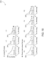
- FIGS. 13-19 show graphs of spring stiffness optimization data.
- exoskeletons for performance enhancement or restoration has been an area of active research for more than fifty years. Most early exoskeletons used kinematic trajectory control, an approach that persists today. However, position control strategies tend to result in less safe and less comfortable human-robot interactions, since they can cause large forces to develop when human and robot motions differ. Position-controlled exoskeletons can also be less effective in rehabilitation compared to traditional human-based therapies.
- exoskeleton control has shifted from kinematic methods to strategies that respond more fluidly to actions of the user.
- One reason for this shift is the concern for human safety and comfort.
- Another driver is an improved understanding of the natural dynamics of human motion, which suggests a more dynamic approach to human-robot interactions than afforded by position control.
- One method for improved interaction between humans and exoskeletons is impedance manipulation, in which the reaction of a robot to external forces is regulated rather than the resulting position trajectory. Whereas position control strategies typically impose high impedance to improve trajectory tracking performance, this method allows lower impedance at the robot interface and a greater influence of human actions on the resulting motions.
- Torque control provides a simple means of manipulating the flow of energy from the exoskeleton to the human, which can be useful in biomechanics studies. Torque control can also be used to exploit passive dynamics or render virtual systems with alternate dynamics in humanoid robots, active prostheses, and exoskeletons. In exoskeletons, the quality of torque control is a limiting factor in precision of the applied intervention and can be the limiting factor in human-exoskeleton system performance.
- Series elastic actuation can improve torque control in exoskeletons, which often include unknown, changing human-exoskeleton interaction dynamics. Elasticity in the actuator transmission decouples motor inertia from the exoskeleton frame, physically reducing interface impedance and resulting in smaller torques when human and exoskeleton motions unexpectedly diverge. Series elastic actuation can thereby provide improved human safety and improve torque tracking performance in the face of complex, dynamic user movements. Unlike direct-drive actuators, torque output in a series elastic actuator is usually not directly related to motor torque, but instead to the position of the motor relative to the joint. Motor position is therefore better correlated to load torque, especially in the presence of transmission friction. For these reasons, series elastic actuators with a motor drive running in velocity mode typically have lower actuation impedance and smoother torque tracking with lower error.
- Flexible Bowden cable transmissions can be in exoskeletons to further reduce physical impedance through drive relocation.
- Bowden cables allow massive motor and gearbox elements to be placed in more desirable locations than the joint they actuate, resulting in reduced exoskeleton inertia. Motors can be moved proximally on the limb or body or off the body altogether.
- Bowden cables are flexible, producing little interference with joint motion, but have complex stick-slip transmission dynamics that pose additional torque control challenges.
- Unidirectional Bowden cables can completely physically isolate the human from motor inertia when desired.
- the capacity to become transparent, or produce zero impedance, is desirable in exoskeletons, as it is frequently useful to apply precisely zero torque to the human.
- Unidirectional Bowden cables can be kept slack, preventing any torque from being transmitted regardless of human dynamics. However, allowing the transmission to become slack introduces complex dynamics and uncertainty during re-engagement, as in other systems with intermittent contact, which can make torque control more difficult.
- the human ankle produces more than half of the mechanical work of the lower limbs during walking and has been a frequent target for exoskeleton assistance.
- ankle joint assistance has led to the first systems that reduce the energy cost of walking for humans, including one device that does so passively.
- Improved torque control at exoskeleton ankle joints would provide immediate benefits for such systems, and could also be beneficial at exoskeleton knee and hip joints.
- Torque control can be found at a low level in exoskeleton control hierarchies, with higher level controllers determining behaviors and commanding desired torques.
- desired torque is not a control objective selected in advance, but rather a mid-level signal, often with complex dynamics that reflect interactions with the human user.
- This document describes the class of control elements that generate desired torque as high-level controllers, and the elements that enforce desired torque (the torque controllers) as low-level controllers. Since the dynamics of the desired torque signal depend on the high-level control type, interactions with low-level controllers will affect torque tracking performance.
- Prominent categories of torque control include classical feedback, model-based control, adaptive control and iterative learning.
- Integral control elements are used to reduce steady state errors in series elastic actuators with consistent dynamics and low impedance.
- Integration-free proportional-derivative (PD) control is often used in high-impedance exoskeletons and in series elastic actuators with more modeling uncertainties.
- Gain scheduling is sometimes used in the control of robots that interact with humans for improved safety or training efficiency.
- Model-based control elements are often used in robots and exoskeletons to improve torque-tracking performance.
- Approaches typically include feed-forward terms that use inverted plant dynamics to shape impedance or torque. This approach works best with an accurate model of the system.
- passivity-based control One example of adaptive control that has been applied to human-robot interaction is passivity-based control. These controllers manipulate the energy balance of the system using a system model and adaptive control elements, and can improve tracking performance with provable closed-loop stability. Passivity-based control has been proposed for series elastic actuators and used during human-robot interactions.
- High-level controllers intended to assist human walking include schemes that command desired torque based on time, joint angle, neuromuscular models, and electromyographic measurements. Perhaps the simplest way to generate desired torques is as a function of time, which can be used to regulate the relative timing of human and exoskeleton actions. Another common method is to imitate observed relationships between human joint angles and joint torques, which can be especially useful in regulating net joint work. Virtual neuromuscular systems with complex internal dynamics have also been used to generate desired joint torques in assistive devices. This method has demonstrated benefits in the control of adaptive prosthetic limbs. Direct neuromuscular interfaces, such as through electromyographic measurement of muscle activity, promise more intuitive control of exoskeletons by users. Each of these high-level control approaches may be advantageous in some assistance paradigm, and each results in desired torque signals with different dynamics.
- a system compares the tracking performance of prominent torque control methods, with multiple high-level desired torque conditions, in a single lower-limb exoskeleton platform, during human walking.
- Promising methods using classical feedback, model-based, adaptive and iterative learning control elements were used.
- the chosen controllers span the set of candidate methods and provide a more comprehensive test than previously available.
- a diverse sample of high-level controllers were used to test for interactions with low-level control dynamics and provide insights into the generality of tracking results.
- a single exoskeleton system was used, to control for hardware capabilities. It was not practical to test multiple exoskeletons. however, and so results might be specific to hardware systems with similar properties.
- Tests were conducted while a human wore the exoskeleton and walked on a treadmill, making results relevant to conditions with complex human-robot interactions. These results to help guide the selection and tuning of torque control elements particularly in lower-limb exoskeletons for locomotion assistance.
- FIG. 1 shows an example exoskeleton system 100 .
- a high speed stand-alone real-time motor controller 110 reads sensory information, computes desired torques, computes desired motor velocity using low level controller, and outputs desired motor velocity to the motor drive.
- the system 100 includes a dedicated motor drive 120 .
- the system 100 includes an off-board geared motor 130 and pulley.
- the system 100 includes a Bowden cable 140 transmission.
- the system 100 includes an ankle exoskeleton 150 , e.g., as described in Witte, Zhang, Jackson, Collins, Design of Two Lightweight, High - Bandwidth Torque - Controlled Ankle Exoskeletons, 2015 IEEE International Conference on Robotics and Automation , p. 1223-1228, incorporated herein in entirety.
- the motor controller 110 is configured to perform one or more of at least nine torque control methods.
- the torque control methods include combinations of classical feedback control, model-based control, adaptive control and iterative learning, as well as model-free and model-based feedback and feedforward control.
- Each low-level torque controller was tested with four high-level walking controllers that set desired torque based on time, ankle angle, a neuromuscular model, or electromyographic measurements.
- the motor controller 110 can be implemented on a tethered ankle-foot exoskeleton with series-elastic actuation driven by a unidirectional Bowden cable and tuned to minimize error.
- the exoskeleton can be worn by a subject who walks on a treadmill for one hundred strides at steady state under each condition, and the root mean squared errors between desired and measured torque are calculated for each stride and for an averaged stride.
- the motor controller 110 is a part of a tethered ankle exoskeleton including a real-time control module and geared electric motor, a unidirectional Bowden cable transmission with a series spring, and an exoskeleton frame that interfaced with the human foot and shank.
- a dedicated real-time control system e.g., ACEI 103, dSPACE Inc., samples sensors at 5000 Hz, filters sensor data at 200 Hz, and generates desired motor velocity commands at 500 Hz.
- the motor unit can be composed of a low-inertia 1.6 kW AC servo motor and a 5:1 planetary gear, with input voltage regulated by a motor driver running in velocity control mode (e.g., BSM90N-175AD, GBSM90-MRP120-S and MFE460AOIOB, Baldor Electric Co.).
- a digital optical encoder e.g., E4, US Digital Corp. measures motor position. As an indication of motor module performance, the 100% rise time to peak motor velocity can be 0.013 s.
- a flexible unidirectional Bowden cable transmits forces from the motor to the exoskeleton frame while minimally restricting leg motions.
- the cable can be composed of a coiled-steel outer conduit (e.g., 415310-00, Lexco Cable Mfg.) and a 0.003 m diameter Vectran® inner rope, and can be approximately 2 m in length.
- a series spring e.g., DWC-148M-12, Diamond Wire Spring Co.
- an effective stiffness of 190 N ⁇ m ⁇ rad ⁇ 1 in terms of ankle rotation
- the exoskeleton frame applies forces on the front of the shank component below the knee, beneath the heel, and beneath the toe, so as to generate an ankle plantarflexion torque in proportion to transmission force.
- Torque is measured using strain gauges (e.g., MMF003129, Micro-Measurements) applied in a full Wheatstone bridge on the heel lever, with 1000 Hz signal conditioning (e.g., CSG110, Futek Inc.).
- Joint angle is measured using a digital optical encoder (e.g., ES, US Digital Corp.).
- gastrocnemius muscle activity can be measured using a wired electromyography system (e.g., Bagnoli 4 EMO System, Delsys Inc.).
- FIG. 2 shows a diagram of an exoskeleton system 200 including high-level and low-level controllers 210 , 220 , motor 230 , transmission cable 240 , and exoskeleton frame 250 .
- the high-level controller uses time, ⁇ , exoskeleton joint angle, ⁇ e , or electromyography, EMG, to determine desired torque.
- the low-level controller regulates torque, using desired torque, ⁇ des , measured torque, ⁇ , motor angle, ⁇ m , and/or exoskeleton angle to command desired motor velocity, ⁇ m,des .
- a hardware motor driver regulates motor velocity. Motor rotations are transmitted through a Bowden cable to one end of a series spring. Together with exoskeleton rotation, this determines spring deflection, which in turn generates exoskeleton torque. Both the user and the series spring exert torques on the exoskeleton frame, the balance of which causes exoskeleton rotation.
- K ⁇ is the motor-torque constant
- i ⁇ is the armature current
- I e is the effective moment of inertia of the motor and gear referred to the motor shaft
- ⁇ m is the angular position of the motor shaft
- ⁇ p is the angular position of the gear output shaft
- ⁇ e is the effective viscous friction coefficient of the combined motor and gear referred to the motor shaft
- ⁇ 0 is output torque at the gear output pulley
- V ⁇ is the armature voltage
- R ⁇ is the armature resistance
- Kb is the motor voltage constant.
- the Bowden cable is modeled as shown below.
- ⁇ 0 F ⁇ r p (2) in which r p is the radius of the pulley attached to the gear output and F is the tension in the cable on the motor side of the conduit.
- the gear ratio of the transmission, R is defined as:
- Motor velocity control dynamics are modeled as shown below.
- the motor and commercial motor driver are operated in a velocity control mode, which results in lower actuation impedance and better torque tracking in series elastic actuators.
- the precise relationship between desired motor velocity, ⁇ m,des , and input voltage to the motor, V a was:
- V a ( R a ⁇ f e K a + K b ) ⁇ ⁇ ⁇ . m + R a K a ⁇ ⁇ o . ( 10 )
- V a ( R a ⁇ f e K a + K b ) ⁇ ⁇ ⁇ . m , ( 11 ) and input voltage and motor velocity are linearly related at moderate, steady speed.
- the cable warms over the course of a many strides, which decreases its overall stiffness.
- the cable exhibits creep, which increases the slack length. If the cable is allowed to go slack, the state corresponding to re-engagement is uncertain. There is substantial friction in the cable, including dissipation with characteristics of Coulomb friction, viscous damping, and stiction, some of which are visible in FIG. 3 .
- the cable heats over the course of many strides, which increases overall friction. Stiction leads to sudden changes in cable force, and propagation of the slipping point along the cable makes these changes unpredictable.
- These transmission properties are complex, nonlinear and time varying. For graph 300 , complex torque is shown against exoskeleton ankle joint angle relationship when motor position was fixed and the exoskeleton was passively flexed for one hundred strides.
- the exoskeleton frame contacts the soft tissues and muscles of a user's body using flexible straps.
- This interface is complex and nonlinear, with low overall impedance.
- muscle activity beneath the straps substantially affects stiffness and damping at the interface. Straps may also shift on the limb, altering lever arms and engaging different tissues.
- Human kinematics, kinetics and underlying neural and muscular activity also vary in time and across steps.
- Graph 400 of FIG. 4 shows the variations in ankle joint angle curves over many steps, even when the motor is fixed.
- graph 400 shows variability in exoskeleton ankle joint angle trajectory during one hundred strides of walking with the motor fixed and the exoskeleton passively flexing.
- Delays in generating desired motor position also pose a control challenge.
- a portion of these delays can come from communication between subsystems. For example, in the hardware used in this system there was a 6 ms closed-loop communication delay. Another effective delay comes from accelerating the motor rotor. The motor velocity rise time was about 7 ms. These delays cause feedback controllers to become unstable as gains are increased, limiting closed-loop performance. The low-level torque controller accommodates these complex, nonlinear, time-varying system features.
- Torque tracking performance varies for different prominent low-level torque control methods.
- Low-level controllers are selected based on prominence in the literature, expected performance based on system modeling, and the results of pilot testing.
- the controllers include model-free and model-based feedback and feedforward elements. Desired torque was set with each of four high-level exoskeleton control strategies, chosen based on prominence in the literature.
- High-level controllers set desired torque based on time, joint angle, a neuromuscular model or electromyography.
- the torque control system includes motor velocity control performed by a dedicated hardware motor controller.
- Series elastic actuators with a drive running in velocity mode typically have lower actuation impedance and smoother torque tracking with lower error than when torque is commanded to the drive.
- controlling motor velocity is similar to controlling the rate of change of exoskeleton torque, since torque is approximated by the product of series stiffness and the difference between motor angle and exoskeleton joint angle (Eq. 6). Desired motor velocity is calculated as:
- T a gain related to rise time
- ⁇ m des is desired change in motor position
- N the motor gear ratio
- ⁇ p des is desired change in pulley position, determined by one of the low-level torque controllers described below.
- the value of T was tuned so as to minimize motor position rise time without causing oscillations during torque tracking.
- the first group of torque controllers used model-free feedback control, comprising variations on classical proportional-integral-derivative control. Gains are tuned systematically using model-free procedures. Four low-level controllers are compared, L 1- L 4.
- the damping term can be more effective than a term with the derivative of torque error. Torque is measured with analog strain gauges, which included substantial noise, while pulley position is measured with a digital encoder.
- This controller is identical to L 1, with the exception that the proportional gain is error-dependent and increased with torque error:
- K* p is the error dependent proportional gain
- h ⁇ and h k are torque error and proportional gain step sizes
- K max is the maximum allowable gain. This is similar to performing proportional control on the square of the torque error, with a sign and gain adjustment. This type of gain scheduling is expected to result in slower corrections, and fewer oscillations, when torque tracking errors are small.
- L 3 Proportional Control with Damping Injection and Previous-Error Compensation (PD*+PEC)
- This approach is expected to increase the control response to large errors. It bears some similarity to integral control, in that it includes a term on prior error, but differs in that only the prior error at the previous sampling time is used rather than the entire time history. In cases where torque error changes slowly, this approach equates to doubling the proportional gain.
- PID* Proportional-Integral Control with Damping Injection
- This controller includes both the classical feedback controller of L 1 and a model-based feedforward term, which anticipates changes in desired motor position due to either changes in exoskeleton joint angle or changes in desired joint torque:
- ⁇ p,des ⁇ K p ⁇ e ⁇ ⁇ K d ⁇ dot over ( ⁇ ) ⁇ p +( ⁇ mdl ⁇ P )
- ⁇ mdl ⁇ e ⁇ tilde over (R) ⁇ des ⁇ tilde over (K) ⁇ i ⁇ 1 (17)
- ⁇ mdl is a model-based motor position compensation generated from Eq. (6)
- ⁇ p is measured motor pulley position
- ⁇ e measured exoskeleton ankle joint angle
- R is the estimate of R as defined in Eq.
- K t is an estimate of K t , which is the total stiffness of the tether, series spring, and other structures between the motor pulley and exoskeleton joint as defined by Eq. (7).
- K t is the total stiffness of the tether, series spring, and other structures between the motor pulley and exoskeleton joint as defined by Eq. (7).
- a change in pulley angle rather than absolute pulley angle, was anticipated based on the rate of change in exoskeleton angle and the rate of change in desired torque. This approach was less stable, owing to the effects of Bowden cable stiction on exoskeleton joint angle and the interplay between user behavior and desired torque through the high-level controller.
- Adaptive control approaches have the capacity to exploit additional knowledge of system dynamics and allow theoretical tests of stability and performance.
- a new adaptive controller was developed for this system using a passivity-based approach, L 6.
- K V r a ⁇ r p ⁇ K a ⁇ K c I e ⁇ NR a
- K 1 1 I e ⁇ ( K a ⁇ K b R a + f e )
- K 2 r p 2 ⁇ K c N 2 ⁇ I e + r a 2 ⁇ K c I e
- K h r a 2 ⁇ K c I e
- S ⁇ is a gain expressed as:
- V a - K p ⁇ e ⁇ - K s ⁇ s + Y d ⁇ ( ⁇ , ⁇ . r , ⁇ ⁇ r , ⁇ . e ) ⁇ ⁇ - K sw ⁇ sign ⁇ ⁇ ( s ) ( 19 )
- K p and e ⁇ are as defined in L 1
- K s is the sliding control gain
- s is the sliding vector, defined below
- Y d is a regressor, defined below
- ⁇ and ⁇ are the system parameter vector and its estimate, defined below
- K sw is the switching term gain.
- Motor controllers can use iterative learning as a feed-forward component, and can improve performance by exploiting the cyclic nature of human gait.
- This controller uses torque error at each instant of one stride to update a feed-forward trajectory of desired motor position for each instant of the next stride. This is a variation on iterative learning, which, more generally, exploits the cyclic nature of a task to compensate complex system dynamics without an explicit model. While walking is not as consistent as the operations of most industrial robots, it is cyclic, which was expected to afford some improvement in torque errors that occurred consistently from stride to stride.
- Iterative learning generates a feed-forward trajectory that tracks torque for an average stride with zero stead-state error regardless of the complexity of the command signal required, but can be susceptible to step-by-step variability.
- Proportional damping control quickly compensates for small torque errors relative to iterative learning, but can be susceptible to rapid changes in desired or measured torque.
- This controller is similar to L 8, and has similar strengths and weaknesses. Differences in motor position are learned rather than absolute positions, however, which eliminates measured motor pulley position, ⁇ p from the formulation. It is therefore a velocity control approach rather than a position control approach. This may affect stability, drift and the level and source of noise in the learned trajectory, which may in turn affect the allowable gains and speed of convergence. Learning desired changes in position also affects interactions between the feedback and feed-forward elements of the controller in the presence of step-by-step variability. Learned changes in position add the same way regardless of present position and error, while the contribution of learned absolute positions depends upon the present motor position. Either approach can oppose feedback contributions under some conditions, but in different ways. A detailed mathematical comparison of these two approaches is provided in Appendix C.
- ⁇ K d ( ⁇ dot over ( ⁇ ) ⁇ dot over ( ⁇ ) ⁇ des ) which involves the derivative of torque error.
- Analog noise in the derivative of measured torque limited the magnitude of the derivative gain that could be applied without causing oscillations. This limited the capacity of the derivative term to stabilize the system, in turn limiting the magnitude of the proportional gains that could be applied.
- the system approximated the derivative term as: ⁇ K d [( ⁇ dot over ( ⁇ ) ⁇ p ⁇ dot over ( ⁇ ) ⁇ e R ) ⁇ dot over ( ⁇ ) ⁇ des ⁇ tilde over (K) ⁇ t ] where the relative velocity between the motor and exoskeleton was substituted for the noisy measured torque derivative.
- the derivative of desired torque is also problematic, however, because it generally cannot be calculated in advance and its numerical approximation online is subject to noise from the human measurements used by the high-level controller to calculate desired torque, for example electromyographic measurements.
- a motor controller using just the relative velocity between the motor pulley and exoskeleton joint is described by: ⁇ K d ( ⁇ dot over ( ⁇ ) ⁇ p ⁇ dot over ( ⁇ ) ⁇ e R ) which is equivalent to making the additional approximation that the derivative of desired torque, ⁇ des , is negligible.
- this control element was also found to be ineffective in pilot tests due to noise on the derivative of the exoskeleton joint angle, which seems to primarily arise from stiction in the Bowden cable transmission.
- desired exoskeleton joint torque was set according to one of four high-level assistance controllers, H 1- H 4, described below.
- This high-level controller set desired torque as a function of time.
- a curve that resembles a scaled-down version of the human ankle moment during unassisted walking can be calculated as:
- ⁇ des 0 ⁇ t ⁇ 0.15 ⁇ ⁇ ⁇ : 0 , 0.15 ⁇ ⁇ ⁇ ⁇ t ⁇ 0.30 ⁇ ⁇ ⁇ : ⁇ p 2 ⁇ sin ⁇ ⁇ ( t cs - 0.15 ⁇ ⁇ ⁇ 0.3 ⁇ ⁇ ⁇ ⁇ ⁇ ) , 0.30 ⁇ ⁇ ⁇ ⁇ t ⁇ 0.45 ⁇ ⁇ ⁇ : - ⁇ p 2 ⁇ cos ⁇ ⁇ ( t cs - 0.3 ⁇ ⁇ ⁇ 0.15 ⁇ ⁇ ⁇ ⁇ ⁇ ) + 3 ⁇ ⁇ p 4 , 0.45 ⁇ ⁇ ⁇ ⁇ t ⁇ 0.60 ⁇ ⁇ ⁇ : ⁇ p 2 ⁇ cos ⁇ ⁇ ( t cs - 0.45 ⁇ ⁇ ⁇ 0.15 ⁇ ⁇ ⁇ ⁇ ⁇ ) + ⁇ p 2 , 0.60 ⁇ ⁇
- This high-level controller sets desired torque as a function of exoskeleton ankle joint angle and phase of the gait cycle.
- This approach is a subset of impedance control, and is similar to setting desired torque based on a phase variable rather than clock time.
- a piece-wise linear curve is used by the controller that resembles a scaled-down version of the human ankle moment during unassisted walking, calculated as:
- ( ⁇ i , ⁇ i ) defines a node in torque-angle space, as seen in graph 600 of FIG. 6 .
- the node ( ⁇ 2 , ⁇ 2 ) marked the transition from the dorsiflexion phase, in which ankle velocity was negative, to the plantarflexion phase, in which ankle velocity was positive. Since the exact transition point varied on each stride, the system uses the angle and torque at the moment of transition, ( ⁇ ′ 2 , ⁇ ′ 2 ). when calculating desired torque in the first portion of Plantarflexion.
- NMM Neuromuscular Model Based Desired Torque
- This high-level controller sets desired exoskeleton torque based on a Hill-type muscle model and apositive force feedback reflex model.
- the resulting dynamics produce human-like motions and muscle activation patterns in simulation and interact well with the human neuromuscular system.
- Virtual muscle-tendon-unit length and velocity are set by measured exoskeleton joint angle and angular velocity.
- Virtual fiber length, velocity and activation were then used to determine muscle-tendon-unit force, F mtu , which, after conditioning, was used to set desired exoskeleton torque.
- the system conditions the force signal by applying a low-pass filter with frequency W q , adding a small negative offset of ⁇ o nmm , and applying a gain of K nmm .
- FIG. 7 shows an example schematic 700 of the neuromuscular control system. High-level parameters are found in Table 2, and a full set of equations and parameters are available in Appendix B, below.
- This high-level controller sets desired torque in proportion to electromyographic measurements from the human gastrocnemius muscle.
- This approach gives the user direct neural control of the device, which makes interactions more intuitive, but can result in more complex desired torque dynamics.
- Electrical activity in the gastrocnemius is measured using surface electrodes and a commercial electromyography system.
- the signal is then high-pass filtered at a frequency of W hp rectified, and low-pass filtered at a frequency of W lp .
- a small negative offset, ⁇ 0 emg was applied, which prevented desired torque generation at low levels of muscle activity.
- the signal is then amplified by a gain, K emg , yielding desired torque.
- FIG. 8 shows a diagram 800 of the proportional electromyography control system. The parameters used by the system can be found in Table 3, below.
- High-level control parameters listed in the prior section were selected so as to result in peak instantaneous desired torques of approximately 45 N-m during the course of one hundred steps of walking.
- Low-level control parameters listed in Table 4 were systematically tuned with the aim of minimizing torque error.
- Feedback, model and adaptive control gains in L 1- L 6 and L 8- L 9 were tuned using a variant of the Ziegler-Nichols method (Ziegler and Nichols, 1942), in which:
- the iterative learning gain in L 7 was tuned such that steady state was reached at approximately 10 strides, which led to a value of K l that was about one tenth the tuned value of K p .
- the same gains were used for iterative learning elements in controllers L 7- L 9.
- the value of R was based on measurements of the motor output pulley radius, motor gear ratio, and exoskeleton lever arm.
- K c was estimated based on measurement of the passive relationship between exoskeleton torque and exoskeleton joint angle measured during walking, as described in relation to FIG. 3 , above.
- Root-mean-squared torque error was calculated for all strides (RMS-E) and for an average stride (RMS-E AVG) across all high- and low-level control combinations.
- a complete table of p values for statistical comparisons between the RMS-E of all torque controllers are provided as Supporting Materials (Tables STI-SV).
- FIGS. S1 -S 2 Ankle angle trajectories in time and torque trajectories in ankle angle space are also provided for all conditions as in Appendix D ( FIGS. S1 -S 2 ). Convergence plots for controllers that involved iterative learning are provided in Appendix D ( FIG. S4 ).
- Model-free proportional control with damping injection compensated by iterative learning resulted in the lowest torque errors for all high-level controllen, both in real-time and for an averaged trajectory.
- This controller resulted in improved normalized torque tracking errors compared to prior exoskeleton torque control techniques.
- FIG. 12 shows a block diagram of controller L 9 PD*+ ⁇ LRN.
- FIG. 11 shows the contributions of each component of the PD*+ ⁇ LRN controller at steps 1 - 10 , steps 51 - 60 and steps 101 - 110 .
- proportional control dominates, and al steady state the learned component dominates. Data shown are from the time-based high-level controller. Plots for all high-level conditions are shown in FIG. S5 of Appendix D.
- Each component of the proportional-learning-damping controller contributes to overall commands in different ways across the learning process.
- proportional control is the primary contributor, moderated by damping injection, while the learned trajectory remains near its initial value, as shown in graph 1100 of FIG. 11 , steps 1 - 10 .
- the proportional gain on torque error is slowly increased until some overshoot and oscillations are observed.
- the damping gain on motor velocity is increased until high-frequency motor oscillations are observed, and the gain is backed off of this limit.
- the proportional gain is then returned such that it is as high as possible without resulting in oscillations in torque error.
- the learning gain is set to a value of one tenth that of the proportional gain and fine-tuned until convergence occurs within the desired time, in this case ten strides.
- a parameter sweep is performed on the delay parameter used to preview learned desired motor position.
- Lopes assists the hip and knee, which have relatively smooth, continuous patterns of joint torque.
- system assisted the ankle joint which typically involves sharper changes in dynamics.
- the foot intermittently contacts the ground, discontinuously changing both the impedance of the ankle joint and the magnitude of desired torques.
- model-based control elements show promise in simulation and in theory, these generally worsened or had no effect on tracking performance.
- the system obtains the best performance by driving model-based contributions to zero.
- One reason for the ineffectiveness of model-based compensation may have been the nonlinear stiffness of the Bowden cable, which was modeled as a linear spring, and slow changes in cable stiffness and length due to heating over the course of each trial. Another reason may have been the exclusion of friction and stiction.
- model-based compensation that included these elements, it was found to make the controller less robust. In each case the effects were highly sensitive to choice of parameter value and torque tracking error was not reduced. Sensitivity to model errors seems to be a fundamental issue in implementing this type of inverse-model control in exoskeletons with Bowden cable transmissions.
- the passivity-based controller fared slightly better, perhaps due to its adaptive nature, but still did not yield substantial benefits.
- One factor that may have limited its effectiveness is input mismatch.
- the controller was designed with motor voltage as input (Eq. 18), but implemented using motor velocity commands instead. While these terms are closely related (Eq. 11), it is possible that an alternate mode of motor control, or an alternate formulation, could have led to improved results.
- Another factor that may have limited performance was the inclusion of a term akin to continuous-time integration, which is subject to windup as discussed above. The primary limitations likely stem from the reliance on any explicit model, however, since the dynamics of this human-exoskeleton system are highly complex and time-varying.
- Error-dependent gains did not provide benefits for any high-level controller. Lower gains when torque errors were low seem to have led to larger errors at other times, since the set point changed rapidly and there were substantial execution delays. Gain scheduling methods that instead use optimal control might improve torque tracking for this system, but such feedback control techniques would still be limited by communication and actuation delays.
- iterative learning realizes another form of optimal control, but uses a feed-forward approach to overcome delays.
- ⁇ m , des ⁇ ( n + 1 ) ⁇ m , des ⁇ ( n ) - e ⁇ ⁇ ( ⁇ m , des ⁇ ( n ) ) K l - 1 ( 33 )
- Low-level torque control can significantly affect human response to high-level assistance modes. For example, changes in the patterns of desired torque and joint kinematics across torque controllers within the same high-level controller reveal an interaction effect. For example, there was more variability in joint kinematics with PD* torque control than with LRN torque control when desired torque was generated on the basis of time. In this case, differences seem to be related to the smoothness of the measured torque generated by the two controllers. The subject reported that the PD* controller had uncomfortable oscillations, leading to compensatory activity, while the LRN controller did not. As another example, there is variability in desired torque with NMM-based assistance than angle-based assistance using PD* torque control, but an opposite trend using LRN torque control.
- the system models the assisted walking with the ankle exoskeleton as an oscillator.
- Oscillators are efficient modeling tools in biological and physical sciences due to their capability to synchronize with other oscillators or with external driving signals. Multiple efforts have been made towards improving the synchronization capabilities of nonlinear oscillators by adapting their frequencies.
- the concept has been introduced and employed in locomotion to either improve the identification of central pattern generator parameters, to better estimate state measurements, or to help with controller design by exploiting the cyclic behavior of walking. Therefore, various states of walking are modeled as synchronized oscillations.
- This method disburdens the analysis from dealing with complicated human-robot interactive dynamics, focus on the resulting states like ankle kinematic profile and required motor position profile that are close to be periodical, and significantly simplified the analysis. However, neglecting of step-to-step variations in practical cases does cause potential deviation of results from theoretical models.
- ⁇ 0 is maximum joint position for the device to exert torque on the human ankle, i.e., the intersection of torque-angle relationship with the angle axis.
- c is an constant denoting the offset of the profile on torque axis
- d n and ⁇ n are the magnitude and phase shift of the n th sinusoidal wave
- t represents the time elapsed within one stride since heel strike.
- the corresponding stabilized motor position should also oscillate with the same frequency.
- K t,opt K des (5.20) Relationship Between Torque Tracking Performance and the Difference of Desired and Passive Stiffnesses
- Eq. (5.24) can be further simplified.
- Successful torque tracking also means a fast changing rate of actual torque compared to the desired torque, ⁇ dot over ( ⁇ ) ⁇ >> ⁇ dot over ( ⁇ ) ⁇ des , which leads to the results of dominance of applied torque changing rate in torque error changing rate, i.e., ⁇ ⁇ ⁇ dot over ( ⁇ ) ⁇ (5.26)
- K p 1 + K d and Kt are inversely proportional to each other.
- the application of Conjecture 1 in this case results in a fixed time constant
- the root-mean-squared torque tracking errors under optimal feedback control conditions are proportional to the absolute difference between the desired and passive stiffness values, i.e., ⁇ e ⁇ ,opt,RMS ⁇ K des ⁇ K t ⁇ . (5.28) Interactions Between Optimal Control Gains and Passive Stiffness
- K p ( K des ⁇ ⁇ . e - e . ⁇ ) ⁇ ( 1 + K d ) ⁇ R - 1 ⁇ e ⁇ - 1 K t - ⁇ . e ⁇ ( 1 + K d ) ⁇ R - 1 ⁇ e ⁇ - 1 . ( 5.29 ) which can be simplified under the same desired torque-angle relationship, i.e., K des .
- a root-mean-squared tracking error of ⁇ 8% the peak desired torque is shown under proportional control and damping injection, which is expected to be improvable with better control parameters and different curve types.
- the optimal proportional gain K p,opt is related to the passive stiffness K t by:
- K p,old is the optimal proportional control gain at K t,old .
- the K d ⁇ K t coefficient in Eq. (5.30) is related to the desired quasi-stiffness K des by:
- ⁇ ⁇ ⁇ K des + ⁇ K des + ⁇ , ( 5.38 ) in which ⁇ , ⁇ and ⁇ are constant parameters, and
- Five piece-wise linear curves, P1, P2, P3, P4 and P5, were then achieved by scaling the unit curve with factors 0.4, 0.7, 1, 1.3 and 1.7.
- the resulting desired torque versus ankle angle curves are shown in graph 1300 of FIG. 13 .
- the effective passive stiffness values of various spring configurations, Kt are evaluated based on passive walking data.
- the human subject walks on the treadmill for at least one hundred steady steps wearing the exoskeleton with the motor position fixed at the position where force starts to be generated with the subject standing in neutral position. Such walking sessions were repeated multiple times for the same passive stiffness.
- the instantaneous value of passive stiffness at each time stamp was calculated and presented in relation to the measured torque values.
- FIG. 14 presents such plots 1400 of passive walking sessions for different spring configurations, one session for each configuration. Median of the instantaneous passive stiffness values within the stabilized region was defined as the stabilized passive stiffness value of the session.
- its stabilized region is defined as a 5.65 Nm torque range, within which the change of trend for the instantaneous passive stiffness averaged over all sessions is minimum.
- the key to be able to compare the influence of passive stiffness on torque tracking performance under a fixed desired quasi-stiffness is to evaluate the ‘best’ tracking performance under each passive stiffness configuration. This was done by evaluating the tracking errors of multiple tests, each with different feedback control gains. The lowest error across these trials was then assigned as the estimate of the actual optimal performance with this passive stiffness.
- the initial session had fairly low proportional and damping gains.
- the gains were gradually increased across trials until perceptible oscillations were detected with maximum damping gain.
- number of trials varies for each stiffness combination.
- the gains are lowered in the final sessions to achieve better gain tuning resolution.
- around ten trials were conducted for each stiffness combination.
- RMS root-mean-squared
- the level of oscillation included in FIG. 15 is an indicator defined to show the amount of oscillations in the control results of each test.
- oscillation level is defined as the mean stride-wise oscillation energy of the torque tracking error signal above 10 Hz.
- the total oscillation energy of a signal s(t) within one stance period is achieved by firstly high-pass filtering it at 10 Hz.
- the filtered signal, x(t) is converted to frequency domain using Fast Fourier Transform.
- the resulting signal in frequency domain, X(f) is used to construct the energy spectral density as X(f) 2 ⁇ Ts 2 .
- the total energy of oscillation of signal s(t) is then calculated as the integral of the energy spectral density.
- the level of oscillation of a signal is then achieved by averaging the stride-wise torque error oscillation energy.
- Estimated optimal tracking errors i.e., the RMS torque errors of the data sets with minimum errors, for linear curves are approximately linearly related to the absolute difference between desired and passive stiffness values as hypothesized by Hypothesis 1 and 2 (graph 1700 of FIG. 17 ). It can be observed that torque errors show strong linear correlation with the absolute value of K t ⁇ K des in cases of both individual desired curves and all curves combined.
- the RMS torque errors of separate phases for data sets with minimum errors are also well correlated to their corresponding differences between the passive and desired stiffnesses (graph 1700 of FIG. 17 ).
- Control gains show interactions with desired and passive stiffnesses (graph 1800 of FIG. 18 ).
- the proportional gains of the trials with minimum errors for all desired curves which are the estimates of optimal proportional gains, saw strong inversely proportional correlation with passive stiffness values (R2 ⁇ 0.565).
- R2 ⁇ 0.565 For each desired curve, data were fitted into a curve with the same format as Eq. (5.30), in which the same ⁇ values were asserted for all curves of the same type, i.e., linear or piece-wise linear. This result agrees with Hypothesis 3, which is based on Conjecture 1.
- the K p ⁇ K t coefficient, ⁇ as identified in FIG. 18 was also seen to be inversely proportional to the desired stiffness (graph 1900 of FIG. 19 ), which agrees with Hypothesis 4 based on Conjecture 1. Note that for each piece-wise linear curve, its effective desired stiffness is defined the mean of phase-wise desired stiffness values averaged over all the six best-performed data sets, one for each spring configuration.
- the optimal proportional gain for a piece-wise linear curve is expected to be higher than the optimal gain for the phase with largest desired stiffness and lower than the one with smallest. This means that the phase-wise torque errors in piece-wise linear curves are noisier than those of linear curves.
- Another issue was that for some phases, for example phase 1 of P1, P2 and P3, the desired torques were very low. Since the Bowden cable rope was still slacking at the beginning of stance, the effective passive stiffness values were actually a lot smaller than the stabilized values used in data analysis. Therefore, many data points as circled in FIG. 17 should be shifted to the left, which will improve the fitting.
- K t ⁇ K des The effective difference in desired and passive stiffness was evaluated, K t ⁇ K des , of piece-wise linear curves for full steps and present torque errors in a way similar to the linear curves in FIG. 17 .
- the effective desired stiffness of piecewise linear curves was generated by linearly fitting the average stride and use it to then calculate K t ⁇ K des .
- Another method was to calculate the difference as the area between desired stiffness versus torque curve and passive stiffness versus torque curve. For both cases, the relationships between torque errors and effective stiffness differences showed significantly less agreement with Eq. (5.28) than FIG. 17 . This suggests that when Hypothesis 1 and 2 are used in guidance to choose passive stiffness, the concerning desired stiffness value K t should be the instantaneous values instead of a collective determined values.
- the first factor is the method used.
- the optimal performance of each desired and passive stiffness combination were achieved by gradually increasing proportional and damping injection gains until perceptible oscillations happen with maximum damping gains.
- the unidirectional Bowden cable is not the dominant factor in the observed patterns of torque error.
- the onset of applied torque tended to lag that of desired torque, particularly with feedback controllers and TIME based desired torque. This pattern might suggest that slack in the Bowden cable as the primary cause of torque error, but this is not the case.
- All high-level controllers set desired torque to zero during the beginning of stance, from about 0 to 0.25 s, consistent with typical human ankle torque patterns. All low-level controllers acted to track desired torque throughout stance, quickly eliminating slack from the previous swing phase early in the period of zero desired torque. The Bowden cable was therefore not slack upon the onset of desired torque.
Abstract
Description
τ0 =F·r p (2)
in which rp is the radius of the pulley attached to the gear output and F is the tension in the cable on the motor side of the conduit. Making the simplifying assumption that there is no friction in the Bowden cable, the torque at the exoskeleton side of the transmission is:
τ=F·r α (3)
in which rα is the lever arm at the ankle joint. The angular excursion of the ankle joint is small, and that the lever arm is therefore approximately constant.
F=K c·(r pθp −r α·θe) (4)
in which Ke is the total effective stiffness of the Bowden cable transmission and series spring and Θp and Θe are the pulley and exoskeleton joint angles relative to a position at which the Bowden cable begins to go slack.
and the torque applied by the exoskeleton can be written as:
with transmission stiffness, Kt, defined as:
K t =r p ·r a ·K c (7)
relating torque at the exoskeleton to the angles of the motor output pulley and exoskeleton joint.
τ−τh −B e·{dot over (θ)}e =I e·{umlaut over (θ)}e (8)
where τh is the torque applied to the exoskeleton by human body, Be is the exoskeleton joint damping coefficient, and Ie is the moment of inertia of the exoskeleton.
and input voltage and motor velocity are linearly related at moderate, steady speed.
where Θm,des is commanded motor velocity, T is a gain related to rise time, ΔΘm,des is desired change in motor position, N is the motor gear ratio, and ΔΘp,des is desired change in pulley position, determined by one of the low-level torque controllers described below. The value of T was tuned so as to minimize motor position rise time without causing oscillations during torque tracking.
Model-Free Feedback Control
Δθp,des =−K p·et −K d·{dot over (θ)}p (13)
where Kp is a proportional gain, eτ=τ−τdes is torque error, r is measured exoskeleton torque, τdes is desired exoskeleton torque, Kd is a damping gain, and Θp is measured velocity of the motor pulley. The damping term can be more effective than a term with the derivative of torque error. Torque is measured with analog strain gauges, which included substantial noise, while pulley position is measured with a digital encoder. Damping is placed on motor pulley velocity alone rather than the relative velocity between the motor pulley and the exoskeleton joint. Using relative velocity can be less effective, likely due to the irregular effects of stiction in the Bowden cable transmission on ankle joint velocity.
where the symbol [•] denotes the ceiling operation, K*p is the error dependent proportional gain, hτ and hk are torque error and proportional gain step sizes, and Kmax is the maximum allowable gain. This is similar to performing proportional control on the square of the torque error, with a sign and gain adjustment. This type of gain scheduling is expected to result in slower corrections, and fewer oscillations, when torque tracking errors are small.
τ′des=τdes −e τ,prev
Δθp,des =−K pec·(τ−τ′des)−K d·{dot over (θ)}p (15)
where τ′des is the compensated torque error and eτprev is the torque error from the previous time step. Kpec is a proportional gain. This approach is expected to increase the control response to large errors. It bears some similarity to integral control, in that it includes a term on prior error, but differs in that only the prior error at the previous sampling time is used rather than the entire time history. In cases where torque error changes slowly, this approach equates to doubling the proportional gain.
Δθp,des =−K p ·e τ −K t·∫i
where Ki is the gain on the integral of torque error, t0 is the time at which the stride began, and t is the present time. Integral control eliminates steady-state error by accumulation of control input (see e.g., Pratt et al., 2004; Wyeth, 2006; Vallery et al., 2007).
Model-Based Feed-Forward Control
Δθp,des =−K p ·e τ −K d·{dot over (θ)}p+(θmdl−θP)
θmdl=θe ·{tilde over (R)}−τ des ·{tilde over (K)} i −1 (17)
where Θmdl is a model-based motor position compensation generated from Eq. (6), Θp is measured motor pulley position, Θe is measured exoskeleton ankle joint angle, R is the estimate of R as defined in Eq. (5), or the ratio of the exoskeleton lever arm to the motor pulley radius, and Kt is an estimate of Kt, which is the total stiffness of the tether, series spring, and other structures between the motor pulley and exoskeleton joint as defined by Eq. (7). This is an inverse dynamics approach similar to computed torque and feedback linearization in nonlinear control. If desired torque remains constant but the exoskeleton joint moves, the motor needs to move in proportion. If the joint is stationary but desired torque changes, the motor moves a predetermined amount to obtain the desired change in torque.
{umlaut over (τ)}+K 1 {dot over (τ)}+K 2 τ+S θ{dot over (θ)}e =K V V a +K hτh (18)
in which τ denotes the torque transmitted to the exoskeleton from the motor, Θe denotes the exoskeleton joint angle, Va is the voltage applied to the armature of the motor, and τh denotes the torque applied to exoskeleton by human body. KV, K1, K2 and Kh are positive gains expressed as:
and SΘ is a gain expressed as:
with definitions of constants provided in Section 2.2. Based on the system model in Eq. (18), a new, provably stable, adaptive controller for the system is shown. The system defines the controller as:
where Kp and eτ are as defined in
s={dot over (τ)}−{dot over (τ)} des +λ·e τ={dot over (τ)}−{dot over (τ)}r
where λ is a positive scalar and τr is a virtual reference torque. The regressor, Yd, is defined as:
s={dot over (τ)}−{dot over (τ)} des +λ·e τ={dot over (τ)}−{dot over (τ)}r
and is used to express the dynamics as linear combination of system parameters as:
Y d(τ,{dot over (τ)}r,{umlaut over (τ)}r,{dot over (θ)}e)=[τ{dot over (τ)}r{umlaut over (τ)}r{dot over (θ)}e],
Γ=K v −1·[1K 1 K 2 S θ]T.
{tilde over ({dot over (Γ)})}=−LY d T s. (20)
where L is a symmetric positive definite parameter adaptation gain matrix. This parameter updating process reduces the model-dependency of controller in Eq. (19), because only the structure of the dynamic model is used in the construction of controller.
S≈{dot over (θ)} p +λ·e τ
Y d≈[τ−λ·e τ−λ·{dot over (θ)}p{dot over (θ)}e]
Model-Free Feed-Forward Control
θp,des(i,n+1)=θp,des(i,n)−K 1 ·e τ(i,n) (22)
where i is the time index or number of control cycles elapsed within this stride, n is this stride and n+1 is the next stride, and K1 is the iterative learning gain. Desired motor position is enforced as:
Δθp,des(i,n)=θp,des(i+D,n)−θp(i,n) (23)
where D is an estimate of the delay between commanding and achieving a change in motor position. During tuning, both K1 and D were adjusted.
θp,des(i,n+1)=β·θp,des(i,n)−K 1 ·e τ(i,n) (24)
where βϵ[0, 1] is a weight on the learned trajectory. For β=1, all leaning is retained, zero steady-state off-set is expected, but ripples can form if the value of D is incorrect. For β<1, torque errors from strides before the last stride have a reduced effect on controller behavior, reducing likelihood of ripple formation, but leading to some steady-state torque offset. For β=0, iterative learning is disabled.
Learning from Filtered Errors
e flt(i,n)=(1−μ)·e flt(i,n−1)+μ·e τ(i,n) (25)
where eflt is the filtered torque error trajectory, initially an array of zeros, used in place of eτ in Eq. (22) and (24), and μϵ[0, 1] is a weighting term on the learned error. For μ=1, only the error from the last stride is used to update the motor trajectory, resulting in faster convergence but larger effects of sensor noise. For μ<1, errors at this time increment from all prior strides have some effect on the motor trajectory update, resulting in slower but more stable convergence. For μ=0, torque error is not updated, and iterative learning is disabled.
θp,des LRN(i,n+1)=β·θp,des LRN(i,n)−K 1 ·e flt(i,n)
θp,des(i,n)=θp,des LRN(i+D,n)−K p ·e τ(i,n)−K d·{dot over (θ)}p(i,n)
Δθp,des(i,n)=θp,des(i,n)−θp(i,n) (26)
Δθp,des LRN(i,n+1)=β·Δθp,des LRN(i,n)−K l ·e flt(i,n)
Δθp,des(i,n)=−K p ·e τ(i,n)−K d{dot over (θ)}p(i,n)+Δθp,des LRN(i+D,n) (27)
−K d({dot over (τ)}−{dot over (τ)}des)
which involves the derivative of torque error. Analog noise in the derivative of measured torque limited the magnitude of the derivative gain that could be applied without causing oscillations. This limited the capacity of the derivative term to stabilize the system, in turn limiting the magnitude of the proportional gains that could be applied.
−K d[({dot over (θ)}p−{dot over (θ)}e R)−{dot over (τ)}des ·{tilde over (K)} t]
where the relative velocity between the motor and exoskeleton was substituted for the noisy measured torque derivative. The derivative of desired torque is also problematic, however, because it generally cannot be calculated in advance and its numerical approximation online is subject to noise from the human measurements used by the high-level controller to calculate desired torque, for example electromyographic measurements.
−K d({dot over (θ)}p−{dot over (θ)}e R)
which is equivalent to making the additional approximation that the derivative of desired torque, τdes, is negligible. However, this control element was also found to be ineffective in pilot tests due to noise on the derivative of the exoskeleton joint angle, which seems to primarily arise from stiction in the Bowden cable transmission.
where t is the time since the current stride began, ξ is stride period and τp is peak torque. ξ=1.1 s and τp=45 N-m, which produces the desired
with curve parameter values as listed in Table 1, below.
| TABLE 1 | ||
| Param | Value | |
| [θ0, τ0] | [0.018, 0.00] | |
| [θ1, τ1] | [−0.122, 18.1] | |
| [θ2, τ2] | [−0.209, 45.2] | |
| [θ3, τ3] | [0.00, 11.3] | |
| [θ4, τ4] | [0.140, 0.00] | |
| TABLE 2 |
| NMM parameter values |
| Param | Value | ||
| KR | 0.002 | ||
| DR | 0.020 s | ||
| PreStim | 0.05 | ||
| | 50 Hz | ||
| τ0 nmm | −20 | ||
| Knmm | 0.057 N · m | ||
| TABLE 3 |
| EMG parameter values |
| | Value | |
| F | ||
| hp | 20 Hz | |
| Kemg | 283 | |
| | 6 Hz | |
| τ0 emg | −0.008 | |
Swing Control
θp,des=θe ·{tilde over (R)},
Δθp,des=θp,des−θp (30)
where Θe, is exoskeleton joint angle and R is the estimated total gear ratio from motor to exoskeleton joint. Maintaining low slack in the Bowden cable reduces the time required for cable winding at the beginning of stance.
-
- 1. All gains (proportional, damping, integral, model, sliding, and/or adaptive) were set to zero.
- 2. The proportional gain was increased until significant oscillations were observed.
- 3. Gain value and oscillation period were then recorded and used to estimate optimal values for proportional and damping gains.
- 4. Fine tuning of gains for all control elements, other than iterative learning, was then performed by the system.
| TABLE 4 |
| Low-level torque control parameter values |
| (Note: l3 denotes a 3 × 3 identity matrix) |
| Param | Value | |
| Kp | 0.093 | |
| Kd | 0.010 | |
| Kmax | 0.15 | |
| Kpec | 0.046 | |
| Ki | 7.7e-5 | |
| hτ | 11.3 N · m | |
| {tilde over (R)} | 2.90 | |
| {tilde over (K)}c | 195 N · m · rad−1 | |
| Ks | 0.005 | |
| λ | 0.077 | |
| L | 1.0e−9l3 | |
| hk | 0.039 | |
| Kl | 0.0077 | |
| D | 0.022 s | |
| |
1 | |
| μ | 1 | |
| T | 0.250 s | |
| |
0 | |
| TABLE 5 |
| Tracking errors with PD* + Δ torque control |
| RMSE | % τmax | RMSE-A | % τmax | ||
| Time | 0.57 ± 0.18 Nm | 1.3% | 0.10 Nm | 0.2% | |
| Angle | 0.99 ± 0.23 Nm | 2.5% | 0.11 Nm | 0.3% | |
| NMM | 0.93 ± 0.32 Nm | 2.3% | 0.12 Nm | 0.3% | |
| EMG | 2.14 ± 0.77 Nm | 5.9% | 0.22 Nm | 0.6% | |
e τ(Δθm,des)=0 (31)
Δθm,des(n+1)=Δθm,des(n)−K l ·e τ(n) (32)
which can be rewritten as:
{dot over (θ)}p={dot over (θ)}p,des. (5.10)
τdes =−K des(θe−θ0), (5.11)
there is:
(1+K d){dot over (θ)}p =−K p[K t(θp R−θ e)+K des(θe−θ0)]. (5.12)
K des −K t=0
will minimize torque tracking error. Therefore, the following hypothesis is made:
K t,opt =K des (5.20)
Relationship Between Torque Tracking Performance and the Difference of Desired and Passive Stiffnesses
K t −K des≠0
with the same step frequency F and angle profile
torque tracking error eτ is inversely proportional to
{dot over (τ)}=K t({dot over (θ)}p R−{dot over (θ)} e) (5.23)
which is a first order dynamics created by feedback control with an effective proportional gain of:
and a time constant of:
{dot over (τ)}≈K t R{dot over (θ)} p. (5.25)
ė τ≈{dot over (τ)} (5.26)
and Kt are inversely proportional to each other. The application of
at optimal control conditions. Together with the assumption of a rather constant step frequency F and a constant angle profile
torque error as expressed by Eq. (5.21) is proportional to the difference between passive and desired stiffness values, i.e.,
e τ,opt ∝K des −K t,
which then leads to the hypothesis below.
∥eτ,opt,RMS ∥∝∥K des −K t∥. (5.28)
Interactions Between Optimal Control Gains and Passive Stiffness
which can be simplified under the same desired torque-angle relationship, i.e., Kdes. A root-mean-squared tracking error of <8% the peak desired torque is shown under proportional control and damping injection, which is expected to be improvable with better control parameters and different curve types. This suggests that under optimal torque tracking conditions, the actual applied torque profiles with the same Kdes, are expected to be fairly constant regardless of the value of passive stiffness Kt. Meanwhile, although the exact exoskeleton-human interactive dynamics is difficult to identify, the relationship between applies torque and resulting human ankle kinematics to obeys of Newton's law. Therefore, a fairly constant torque profile from the exoskeleton, when applied to the same subject under the same walking speed and step frequencies with low variance, should produce rather constant human and device joint kinematics, θe and θ′e. Therefore, the extreme device joint velocity that would produce the highest torque error rate with fixed control gains and push the controlled system to its bandwidth limit, θe,ext, does not vary significantly across different passive stiffness conditions. Similar assumptions can be made about the extreme torque error eτ,ext. On the other hand, gain of the less dominant damping injection control part, Kd, have been observed to be upper-bounded by the appearance of motor juddering at Kd,max=0.6 for various stiffness combinations. The approximated invariance of θe,ext and Kd,max, combined with a fixed eτ,max as assumed by
in which σ is dependent on the desired stiffness Kdes and can be expressed as:
σ=(K des{dot over (θ)}e,ext −ė τ,max)(1+K d,max)R −1 e τ,ext −1 (5.31)
and the constant is:
λ=−{dot over (θ)}e,ext(1+K d,max)R −1 e τ,ext −1 (5.32)
{dot over (θ)}p,des ≈K p e τ (5.33)
and accordingly, Eq. (5.27) becomes:
ė τ ≈−K l RK p e τ (5.34)
which suggests that
in which Kp,old is the optimal proportional control gain at Kt,old. Although multiple approximations have been made in the derivation of this corollary, which causes inaccuracies in this estimation, it can be used to set a starting point of proportional control gain tuning when system passive stiffness is changed with only the knowledge of the old and new passive stiffness values.
Relationship Between Kp−Kt Coefficient and Desired Stiffness
ė τ,max =−σR(1+K d,max)−1 e τ +K des{dot over (θ)}e
=−σR(1+K d,max)−1[τ+K des(θe−θ0)]+K des{dot over (θ)}e (5.36)
which means:
in which ζ, δ and ξ are constant parameters, and
is linearly related to the hypothesized maximum commanded torque change rate eτ,max.
| TABLE 5.1 |
| Linear unit curve parameter values |
| Param | Value | |
| [θ0, l τ0, l] | [−2, 0] | |
| |
5 | |
| TABLE 5.2 |
| Piece-wise linear unit curve parameter values |
| Param | Value | |
| [θ0, p τ0, p] | [−2, 0] | |
| [θ2, p τ2, p] | [−12, 50] | |
| [θ4, p τ4, p] | [8, 0] | |
| [θ1, p τ1, p] | [−8, 20] | |
| [θ3, p τ3, p] | [0, 12.5] | |
| TABLE 5.3 |
| List of springs used in experiments with assigned ID |
| Passive Stiffness | ||||||
| ID | S1 | S2 | S3 | S4 | S5 | S6 |
| Spring Part No. | DWC-148M-13 | DWC-162M-12 | DWC-187M-12 | DWC-225M-13 | DWC-250M-12 | No Spring |
| Length (m) | 0.635 | 0.0508 | 0.0508 | 0.0635 | 0.0508 | — |
| Spring Rate | 15.1 | 27.5 | 50.1 | 103.1 | 235.7 | — |
| (N/m × 103) | ||||||
| Max Load (N) | 413.7 | 578.3 | 778.4 | 1641.4 | 2246.4 | — |
| TABLE 5.4 |
| List of measured stabilized passive stiffness values |
| Passive Stiffness ID | S1 | S2 | S3 | S4 | S5 | S6 | ||
| Kt (Nm/deg) | 1.9 | 2.8 | 3.7 | 4.7 | 5.6 | 5.9 | ||
e τ,opt,RMS =a·∥K t −K des ∥+b (5.40)
with a coefficient of determinant R2=0.839 at a slope of a=0.355 for the absolute ones and R2=0.854 at a=0.869 for the relative ones.
Claims (32)
Priority Applications (1)
| Application Number | Priority Date | Filing Date | Title |
|---|---|---|---|
| US15/605,520 US10555865B2 (en) | 2016-05-25 | 2017-05-25 | Torque control methods for an exoskeleton device |
Applications Claiming Priority (2)
| Application Number | Priority Date | Filing Date | Title |
|---|---|---|---|
| US201662392270P | 2016-05-25 | 2016-05-25 | |
| US15/605,520 US10555865B2 (en) | 2016-05-25 | 2017-05-25 | Torque control methods for an exoskeleton device |
Publications (2)
| Publication Number | Publication Date |
|---|---|
| US20170340506A1 US20170340506A1 (en) | 2017-11-30 |
| US10555865B2 true US10555865B2 (en) | 2020-02-11 |
Family
ID=60421172
Family Applications (1)
| Application Number | Title | Priority Date | Filing Date |
|---|---|---|---|
| US15/605,520 Active 2037-09-14 US10555865B2 (en) | 2016-05-25 | 2017-05-25 | Torque control methods for an exoskeleton device |
Country Status (1)
| Country | Link |
|---|---|
| US (1) | US10555865B2 (en) |
Families Citing this family (29)
| Publication number | Priority date | Publication date | Assignee | Title |
|---|---|---|---|---|
| US8075633B2 (en) * | 2003-09-25 | 2011-12-13 | Massachusetts Institute Of Technology | Active ankle foot orthosis |
| US11921471B2 (en) | 2013-08-16 | 2024-03-05 | Meta Platforms Technologies, Llc | Systems, articles, and methods for wearable devices having secondary power sources in links of a band for providing secondary power in addition to a primary power source |
| US20150124566A1 (en) | 2013-10-04 | 2015-05-07 | Thalmic Labs Inc. | Systems, articles and methods for wearable electronic devices employing contact sensors |
| US10188309B2 (en) | 2013-11-27 | 2019-01-29 | North Inc. | Systems, articles, and methods for electromyography sensors |
| US10555865B2 (en) * | 2016-05-25 | 2020-02-11 | Carnegie Mellon University | Torque control methods for an exoskeleton device |
| US11000211B2 (en) * | 2016-07-25 | 2021-05-11 | Facebook Technologies, Llc | Adaptive system for deriving control signals from measurements of neuromuscular activity |
| WO2020112986A1 (en) | 2018-11-27 | 2020-06-04 | Facebook Technologies, Inc. | Methods and apparatus for autocalibration of a wearable electrode sensor system |
| KR102510874B1 (en) | 2017-06-15 | 2023-03-16 | 삼성전자주식회사 | Method for walking assist, and devices operating the same |
| US11717187B2 (en) * | 2017-06-15 | 2023-08-08 | Samsung Electronics Co., Ltd. | Walking assistance method and apparatuses |
| US11491074B2 (en) | 2017-07-17 | 2022-11-08 | Carnegie Mellon University | Exoskeleton device emulation system |
| WO2019060791A1 (en) * | 2017-09-22 | 2019-03-28 | North Carolina State University | Hip exoskeleton |
| EP3697297A4 (en) | 2017-10-19 | 2020-12-16 | Facebook Technologies, Inc. | Systems and methods for identifying biological structures associated with neuromuscular source signals |
| US11150730B1 (en) | 2019-04-30 | 2021-10-19 | Facebook Technologies, Llc | Devices, systems, and methods for controlling computing devices via neuromuscular signals of users |
| US11907423B2 (en) | 2019-11-25 | 2024-02-20 | Meta Platforms Technologies, Llc | Systems and methods for contextualized interactions with an environment |
| US11493993B2 (en) | 2019-09-04 | 2022-11-08 | Meta Platforms Technologies, Llc | Systems, methods, and interfaces for performing inputs based on neuromuscular control |
| US11961494B1 (en) | 2019-03-29 | 2024-04-16 | Meta Platforms Technologies, Llc | Electromagnetic interference reduction in extended reality environments |
| US11481030B2 (en) | 2019-03-29 | 2022-10-25 | Meta Platforms Technologies, Llc | Methods and apparatus for gesture detection and classification |
| WO2020061451A1 (en) | 2018-09-20 | 2020-03-26 | Ctrl-Labs Corporation | Neuromuscular text entry, writing and drawing in augmented reality systems |
| KR20200085083A (en) * | 2019-01-04 | 2020-07-14 | 삼성전자주식회사 | Method and apparatus for controlling walking assist device |
| US20200268541A1 (en) * | 2019-02-22 | 2020-08-27 | The Government Of The United States, As Represented By The Secretary Of The Army | Spring Engagement and Disengagement During Gait Cycle |
| CN110412866B (en) * | 2019-05-14 | 2022-12-23 | 上海大学 | Exoskeleton single-leg cooperative control method based on adaptive iterative learning |
| EP4025127A4 (en) * | 2019-09-06 | 2023-09-27 | The University of Miami | Quantification of symmetry and repeatability in limb motion for treatment of abnormal motion patterns |
| CN112068435B (en) * | 2020-09-09 | 2021-07-16 | 北京航空航天大学 | Rehabilitation mechanical device iterative learning control method and system based on disturbance observer |
| CN112372637B (en) * | 2020-10-27 | 2022-05-06 | 东方红卫星移动通信有限公司 | Adaptive impedance compliance control method, module and system for low-orbit satellite space manipulator |
| US11868531B1 (en) | 2021-04-08 | 2024-01-09 | Meta Platforms Technologies, Llc | Wearable device providing for thumb-to-finger-based input gestures detected based on neuromuscular signals, and systems and methods of use thereof |
| CN113255208B (en) * | 2021-04-21 | 2023-05-12 | 杭州新剑机器人技术股份有限公司 | Neural network model predictive control method for series elastic actuator of robot |
| CN113442114A (en) * | 2021-06-04 | 2021-09-28 | 迈宝智能科技(苏州)有限公司 | Waist assistance exoskeleton and control method thereof |
| KR20240036769A (en) * | 2022-09-13 | 2024-03-21 | 삼성전자주식회사 | Wearable apparatus and operating method thereof |
| CN115755592B (en) * | 2023-01-10 | 2023-05-12 | 常熟理工学院 | Multi-mode control method for adjusting motion state of three-degree-of-freedom exoskeleton and exoskeleton |
Citations (15)
| Publication number | Priority date | Publication date | Assignee | Title |
|---|---|---|---|---|
| US20100113980A1 (en) * | 2008-09-04 | 2010-05-06 | Iwalk, Inc. | Hybrid Terrain-Adaptive Lower-Extremity Systems |
| US20100114329A1 (en) * | 2005-03-31 | 2010-05-06 | Iwalk, Inc. | Hybrid terrain-adaptive lower-extremity systems |
| US20100324699A1 (en) * | 2005-03-31 | 2010-12-23 | Massachusetts Institute Of Technology | Model-Based Neuromechanical Controller for a Robotic Leg |
| US20110130761A1 (en) * | 2005-04-07 | 2011-06-02 | Perception Raisonnement Action En Medecine | Robotic guide assembly for use in computer-aided surgery |
| US20120330198A1 (en) * | 2011-06-21 | 2012-12-27 | Volkan Patoglu | Exoskeleton |
| US20130289452A1 (en) * | 2011-07-29 | 2013-10-31 | Global Medical Device Partners, Inc. | Exoskeleton for gait assistance and rehabilitation |
| US20150141878A1 (en) * | 2013-11-20 | 2015-05-21 | The University Of Maryland, Baltimore | Method and apparatus for providing deficit-adjusted adaptive assistance during movement phases of an impaired joint |
| US20150173993A1 (en) * | 2012-09-17 | 2015-06-25 | President And Fellows Of Harvard College | Soft exosuit for assistance with human motion |
| US20150297934A1 (en) * | 2014-04-21 | 2015-10-22 | The Trustees Of Columbia University In The City Of New York | Active movement training devices, methods, and systems |
| US20160107309A1 (en) * | 2013-05-31 | 2016-04-21 | President And Fellows Of Harvard College | Soft Exosuit for Assistance with Human Motion |
| US20170202724A1 (en) * | 2013-12-09 | 2017-07-20 | President And Fellows Of Harvard College | Assistive Flexible Suits, Flexible Suit Systems, and Methods for Making and Control Thereof to Assist Human Mobility |
| US20170231787A1 (en) * | 2014-09-12 | 2017-08-17 | Advanced Telecommunications Research Institute International | Actuator device, power assist robot and humanoid robot |
| US20170340506A1 (en) * | 2016-05-25 | 2017-11-30 | Carnegie Mellon University | Torque control methods for an exoskeleton device |
| US20180160946A1 (en) * | 2015-06-22 | 2018-06-14 | University Of Maryland, Baltimore | Method and Apparatus for Providing Economical, Portable Deficit-Adjusted Adaptive Assistance During Movement Phases of an Impaired Ankle |
| US20180325713A1 (en) * | 2017-05-11 | 2018-11-15 | Board Of Regents, The University Of Texas System | Lower limb powered orthosis with low ratio actuation |
-
2017
- 2017-05-25 US US15/605,520 patent/US10555865B2/en active Active
Patent Citations (15)
| Publication number | Priority date | Publication date | Assignee | Title |
|---|---|---|---|---|
| US20100114329A1 (en) * | 2005-03-31 | 2010-05-06 | Iwalk, Inc. | Hybrid terrain-adaptive lower-extremity systems |
| US20100324699A1 (en) * | 2005-03-31 | 2010-12-23 | Massachusetts Institute Of Technology | Model-Based Neuromechanical Controller for a Robotic Leg |
| US20110130761A1 (en) * | 2005-04-07 | 2011-06-02 | Perception Raisonnement Action En Medecine | Robotic guide assembly for use in computer-aided surgery |
| US20100113980A1 (en) * | 2008-09-04 | 2010-05-06 | Iwalk, Inc. | Hybrid Terrain-Adaptive Lower-Extremity Systems |
| US20120330198A1 (en) * | 2011-06-21 | 2012-12-27 | Volkan Patoglu | Exoskeleton |
| US20130289452A1 (en) * | 2011-07-29 | 2013-10-31 | Global Medical Device Partners, Inc. | Exoskeleton for gait assistance and rehabilitation |
| US20150173993A1 (en) * | 2012-09-17 | 2015-06-25 | President And Fellows Of Harvard College | Soft exosuit for assistance with human motion |
| US20160107309A1 (en) * | 2013-05-31 | 2016-04-21 | President And Fellows Of Harvard College | Soft Exosuit for Assistance with Human Motion |
| US20150141878A1 (en) * | 2013-11-20 | 2015-05-21 | The University Of Maryland, Baltimore | Method and apparatus for providing deficit-adjusted adaptive assistance during movement phases of an impaired joint |
| US20170202724A1 (en) * | 2013-12-09 | 2017-07-20 | President And Fellows Of Harvard College | Assistive Flexible Suits, Flexible Suit Systems, and Methods for Making and Control Thereof to Assist Human Mobility |
| US20150297934A1 (en) * | 2014-04-21 | 2015-10-22 | The Trustees Of Columbia University In The City Of New York | Active movement training devices, methods, and systems |
| US20170231787A1 (en) * | 2014-09-12 | 2017-08-17 | Advanced Telecommunications Research Institute International | Actuator device, power assist robot and humanoid robot |
| US20180160946A1 (en) * | 2015-06-22 | 2018-06-14 | University Of Maryland, Baltimore | Method and Apparatus for Providing Economical, Portable Deficit-Adjusted Adaptive Assistance During Movement Phases of an Impaired Ankle |
| US20170340506A1 (en) * | 2016-05-25 | 2017-11-30 | Carnegie Mellon University | Torque control methods for an exoskeleton device |
| US20180325713A1 (en) * | 2017-05-11 | 2018-11-15 | Board Of Regents, The University Of Texas System | Lower limb powered orthosis with low ratio actuation |
Non-Patent Citations (9)
| Title |
|---|
| Juanjuan Zhang et al., "Experimental comparison of torque control methods on an ankle exoskeleton during human walking," IEEE, (2015), pp. 5584-5589. |
| Juanjuan Zhang et al., "Stable Human-Robot Interaction Control for Upper-limb Rehabilitation Robotics," 2013 IEEE International Conference on Robotics and Automation (ICRA), pp. 1-6. |
| Juanjuan Zhang et al., "Supporting Materials: Comparison of torque control methods for tethered lower-limb exoskeletons during human walking," International Journal of Robotics Research (2015), pp. 1-9. |
| Seungmoon Song et al., "The Effect of Foot Compliance Encoded in the Windlass Mechanism on the Energetics of Human Walking," 35th Annual International Conference on the IEEE EMBS, 2013, pp. 1-4. |
| Steven H. Collins and Rachel W. Jackson, "Inducing Self-Selected Human Engagement in Robotic Locomotion Training," 2013 IEEE International Conference on Rehabiliation Robotics, pp. 1-6. |
| Van der Helm et al., "Changing Speed in a Simple Walker with Dynamic One-Step Transitions," Master Thesis, 2009, pp. 1-20. |
| Wiggen et al., "An Exoskeleton Using Controlled Energy Storage and Release to Aid Ankle Propulsion," 2011 IEEE International Conference on Rehabilitation Robotics, pp. 1-5. |
| Wiggin et al., "An Exoskeleton Using Controlled Energy Storage and Release to Aid Ankle Propulsion," 2011 IEEE International Conference on Rehabilitation Robotics, 2011, pp. 1-5. |
| Witte et al., Design of Two Lightweight, High-Bandwidth Torque-Controlled Ankle Exoskeletons, 2015 IEEE International Conference on Robotics and Automation, p. 1-2. |
Also Published As
| Publication number | Publication date |
|---|---|
| US20170340506A1 (en) | 2017-11-30 |
Similar Documents
| Publication | Publication Date | Title |
|---|---|---|
| US10555865B2 (en) | Torque control methods for an exoskeleton device | |
| Zhang et al. | Torque control in legged locomotion | |
| Liu et al. | Impedance-controlled variable stiffness actuator for lower limb robot applications | |
| Liu et al. | Design and control of a mechanical rotary variable impedance actuator | |
| Yu et al. | Human–robot interaction control of rehabilitation robots with series elastic actuators | |
| Kong et al. | Control of rotary series elastic actuator for ideal force-mode actuation in human–robot interaction applications | |
| Emken et al. | Human-robot cooperative movement training: learning a novel sensory motor transformation during walking with robotic assistance-as-needed | |
| Jezernik et al. | Sliding mode closed-loop control of FES controlling the shank movement | |
| Sergi et al. | Design and characterization of a compact rotary series elastic actuator for knee assistance during overground walking | |
| US20180125738A1 (en) | Exoskeleton device and control system | |
| Sharifi et al. | Adaptive CPG-based gait planning with learning-based torque estimation and control for exoskeletons | |
| Lu et al. | Design and torque-mode control of a cable-driven rotary series elastic actuator for subject-robot interaction | |
| Tu et al. | A data-driven reinforcement learning solution framework for optimal and adaptive personalization of a hip exoskeleton | |
| JP7054130B2 (en) | Motor learning support device and motor learning support method | |
| Taherifar et al. | Assistive-compliant control of wearable robots for partially disabled individuals | |
| Narayan et al. | Adaptive iterative learning-based gait tracking control for paediatric exoskeleton during passive-assist rehabilitation | |
| Kaneishi et al. | Optimal control parameterization for activelpassive exoskeleton with variable impedance actuator | |
| Stollenmaier et al. | Simulating the response of a neuro-musculoskeletal model to assistive forces: implications for the design of wearables compensating for motor control deficits | |
| Ballesteros-Escamilla et al. | Hybrid position/force output feedback second-order sliding mode control for a prototype of an active orthosis used in back-assisted mobilization | |
| Kong et al. | Mechanical design and impedance compensation of SUBAR (Sogang University’s Biomedical Assist Robot) | |
| Caputo | Informing ankle-foot prosthesis design and prescription through systematic experimentation with a tethered robotic prosthesis | |
| Wei et al. | Adaptive iterative learning control design for RUPERT IV | |
| Rinderknecht et al. | Assistance using adaptive oscillators: Robustness to errors in the identification of the limb parameters | |
| Zhang et al. | Compensation of time delay in a network-based gait rehabilitation system with a discrete-time communication disturbance observer | |
| Anwar et al. | Adaptive trajectory control to achieve smooth interaction force in robotic rehabilitation device |
Legal Events
| Date | Code | Title | Description |
|---|---|---|---|
| STPP | Information on status: patent application and granting procedure in general |
Free format text: NON FINAL ACTION MAILED |
|
| STPP | Information on status: patent application and granting procedure in general |
Free format text: RESPONSE TO NON-FINAL OFFICE ACTION ENTERED AND FORWARDED TO EXAMINER |
|
| STPP | Information on status: patent application and granting procedure in general |
Free format text: NOTICE OF ALLOWANCE MAILED -- APPLICATION RECEIVED IN OFFICE OF PUBLICATIONS |
|
| AS | Assignment |
Owner name: CARNEGIE MELLON UNIVERSITY, PENNSYLVANIA Free format text: ASSIGNMENT OF ASSIGNORS INTEREST;ASSIGNORS:ZHANG, JUANJUAN;COLLINS, STEVEN H.;SIGNING DATES FROM 20180220 TO 20190930;REEL/FRAME:051006/0974 |
|
| STPP | Information on status: patent application and granting procedure in general |
Free format text: NOTICE OF ALLOWANCE MAILED -- APPLICATION RECEIVED IN OFFICE OF PUBLICATIONS |
|
| STPP | Information on status: patent application and granting procedure in general |
Free format text: PUBLICATIONS -- ISSUE FEE PAYMENT VERIFIED |
|
| STCF | Information on status: patent grant |
Free format text: PATENTED CASE |
|
| CC | Certificate of correction | ||
| MAFP | Maintenance fee payment |
Free format text: PAYMENT OF MAINTENANCE FEE, 4TH YR, SMALL ENTITY (ORIGINAL EVENT CODE: M2551); ENTITY STATUS OF PATENT OWNER: SMALL ENTITY Year of fee payment: 4 |