US10503633B2 - Symbolic execution of alternative branches - Google Patents
Symbolic execution of alternative branches Download PDFInfo
- Publication number
- US10503633B2 US10503633B2 US15/084,617 US201615084617A US10503633B2 US 10503633 B2 US10503633 B2 US 10503633B2 US 201615084617 A US201615084617 A US 201615084617A US 10503633 B2 US10503633 B2 US 10503633B2
- Authority
- US
- United States
- Prior art keywords
- branch
- symbolic
- execution
- state
- symbolic state
- Prior art date
- Legal status (The legal status is an assumption and is not a legal conclusion. Google has not performed a legal analysis and makes no representation as to the accuracy of the status listed.)
- Expired - Fee Related, expires
Links
- 238000000034 method Methods 0.000 claims abstract description 25
- 238000004590 computer program Methods 0.000 claims description 42
- 238000003860 storage Methods 0.000 claims description 18
- 230000001143 conditioned effect Effects 0.000 claims description 11
- 230000000694 effects Effects 0.000 claims description 8
- 238000010586 diagram Methods 0.000 description 13
- 230000006870 function Effects 0.000 description 9
- 230000014509 gene expression Effects 0.000 description 6
- 230000003068 static effect Effects 0.000 description 5
- 230000005540 biological transmission Effects 0.000 description 4
- 238000004880 explosion Methods 0.000 description 4
- 238000005192 partition Methods 0.000 description 3
- 238000004458 analytical method Methods 0.000 description 2
- 238000003491 array Methods 0.000 description 2
- 239000000463 material Substances 0.000 description 2
- 238000012986 modification Methods 0.000 description 2
- 230000004048 modification Effects 0.000 description 2
- 230000003287 optical effect Effects 0.000 description 2
- 230000001902 propagating effect Effects 0.000 description 2
- RYGMFSIKBFXOCR-UHFFFAOYSA-N Copper Chemical compound [Cu] RYGMFSIKBFXOCR-UHFFFAOYSA-N 0.000 description 1
- 230000003750 conditioning effect Effects 0.000 description 1
- 229910052802 copper Inorganic materials 0.000 description 1
- 239000010949 copper Substances 0.000 description 1
- 230000001419 dependent effect Effects 0.000 description 1
- 239000000835 fiber Substances 0.000 description 1
- 238000004519 manufacturing process Methods 0.000 description 1
- 231100000957 no side effect Toxicity 0.000 description 1
- 238000005457 optimization Methods 0.000 description 1
- 239000004065 semiconductor Substances 0.000 description 1
- 238000000638 solvent extraction Methods 0.000 description 1
- 230000001131 transforming effect Effects 0.000 description 1
- 238000012795 verification Methods 0.000 description 1
Images


Classifications
-
- G—PHYSICS
- G06—COMPUTING; CALCULATING OR COUNTING
- G06F—ELECTRIC DIGITAL DATA PROCESSING
- G06F11/00—Error detection; Error correction; Monitoring
- G06F11/36—Preventing errors by testing or debugging software
- G06F11/3668—Software testing
-
- G—PHYSICS
- G06—COMPUTING; CALCULATING OR COUNTING
- G06F—ELECTRIC DIGITAL DATA PROCESSING
- G06F11/00—Error detection; Error correction; Monitoring
- G06F11/36—Preventing errors by testing or debugging software
- G06F11/3604—Software analysis for verifying properties of programs
- G06F11/3608—Software analysis for verifying properties of programs using formal methods, e.g. model checking, abstract interpretation
-
- G—PHYSICS
- G06—COMPUTING; CALCULATING OR COUNTING
- G06F—ELECTRIC DIGITAL DATA PROCESSING
- G06F11/00—Error detection; Error correction; Monitoring
- G06F11/36—Preventing errors by testing or debugging software
- G06F11/3668—Software testing
- G06F11/3672—Test management
- G06F11/3688—Test management for test execution, e.g. scheduling of test suites
Definitions
- the present disclosure relates to symbolic execution of computer programs in general, and to symbolic execution of computer programs having alternative branches, in particular.
- Symbolic execution combines explicit exploration of every feasible execution path of a computer program with a symbolic representation of input values. Symbols are injected instead of input values, where a symbol represents any value in the corresponding domain. Using the symbolic values, properties relating to every potential execution of the execution path may be analyzed. For example, absence of failures on all possible inputs that lead the program through this execution path may be determined or a counter-example may be provided to demonstrate such failure.
- Symbolic execution can be implemented in a variety of manners.
- the computer program is compiled to create an executable file which is configured to perform the symbolic execution when executed.
- an interpreter is used to interpret the computer program and simulate symbolic execution thereof.
- “symbolic execution” covers both these implementations, as well as any other implementation.
- Symbolic execution suffers from a drawback known as path explosion.
- path explosion As each execution path of the program is traversed, symbolic execution may not be feasible when there are many execution paths that need to be traversed. Such may be the case when, during execution, there is a sequence of branches each of which spawns more than one feasible sub-path, thereby increasing the number of the total paths exponentially in the number of branches.
- One exemplary embodiment of the disclosed subject matter is a computer-implemented method for performing symbolic execution of a computer program, wherein the symbolic execution traverses a Control Flow Graph (CFG) of the computer program while updating a symbolic state of the computer program, the method comprising: reaching a branching node in the CFG with a first symbolic state, wherein the branching has at least a first branch and a second branch, wherein the first and second branches end at a joining node in the CFG; symbolically executing the first branch using the first symbolic state, whereby a second symbolic state is determined; and symbolically executing the second branch using the second symbolic state, whereby a third symbolic state is determined, the third symbolic state is based on sequential symbolic execution of alternative branches.
- CFG Control Flow Graph
- Another exemplary embodiment of the disclosed subject matter is an apparatus for performing symbolic execution of a computer program, wherein the symbolic execution traverses a Control Flow Graph (CFG) of the computer program while updating a symbolic state of the computer program
- the apparatus comprising a processor being adapted to perform the steps of: reaching a branching node in the CFG with a first symbolic state, wherein the branching has at least a first branch and a second branch, wherein the first and second branches end at a joining node in the CFG; symbolically executing the first branch using the first symbolic state, whereby a second symbolic state is determined; and symbolically executing the second branch using the second symbolic state, whereby a third symbolic state is determined, the third symbolic state is based on sequential symbolic execution of alternative branches.
- CFG Control Flow Graph
- Yet another exemplary embodiment of the disclosed subject matter is a computer program product for performing symbolic execution of a computer program, wherein the symbolic execution traverses a Control Flow Graph (CFG) of the computer program while updating a symbolic state of the computer program
- the computer program product comprising a computer readable storage medium retaining program instructions, which program instructions when read by a processor, cause the processor to perform a method comprising: reaching a branching node in the CFG with a first symbolic state, wherein the branching has at least a first branch and a second branch, wherein the first and second branches end at a joining node in the CFG; symbolically executing the first branch using the first symbolic state, whereby a second symbolic state is determined; and symbolically executing the second branch using the second symbolic state, whereby a third symbolic state is determined, the third symbolic state is based on sequential symbolic execution of alternative branches.
- CFG Control Flow Graph
- FIG. 1 shows a schematic illustration of a Control Flow Graph (CFG), in accordance with some exemplary embodiments of the disclosed subject matter.
- CFG Control Flow Graph
- FIG. 2 shows a flowchart diagram, in accordance with some exemplary embodiments of the subject matter.
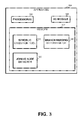
- FIG. 3 shows a block diagram of an apparatus, in accordance with some exemplary embodiments of the disclosed subject matter.
- One technical problem dealt with by the disclosed subject matter is to provide for a method, system or product capable of symbolic execution of a program comprising alternative branches.
- Symbolic execution may be performed by traversing a Control Flow Graph (CFG) of the computer program.
- the CFG is a static representation of the computer program which comprises nodes representing instructions in the program, and directed edges connect two nodes (source node and target node) if after executing the instruction of the source node, the control flow may pass to the instruction of the target node.
- Symbolic execution may lead to a path explosion problem.
- the number of feasible execution paths may be exponential, and the symbolic execution tool may be unable to provide meaningful verification result.
- the problem may occur when a symbolic execution tool reaches nondeterministic branches, for example, in case a branch having a nondeterministic branch condition appears inside a loop. In such a case, an efficient symbolic execution of the alternative branches may be desired so as to allow the symbolic execution of the computer program to be feasible.
- Path explosion problem harms scalability of tools that apply symbolic execution on the code.
- proving the code correctness may become an infeasible task since both time and memory constraints become insufficient for covering this huge number of spawn execution paths.
- bug hunting abilities may also be harmed because the tool may get stuck in spawning more and more feasible execution paths, without making a real progress into the more interesting areas in the code.
- One technical solution is to symbolically execute alternative branches in sequential manner. Without loss of generality, consider a branching node having two alternative branches, such as an if-then-else control scheme. A first branch may be symbolically executed until reaching a joining node in the CFG. The symbolic state that was determined during the symbolic execution of the first branch is manipulated and used again as if it was the state when the branching node was reached. Then, the second branch is symbolically executed using the same symbolic state.
- both execution paths are performed sequentially and without splitting the state.
- ITE constructs may be used where the condition of the ITE construct is a condition required to follow the execution path in which the instruction was performed.
- the ITE construct may be a triplet (exp, value 1 , value 2 ), where exp is a condition, if the condition is true than the value of the ITE construct is value 1 , otherwise, the value is value 2 .
- exp is a condition
- the variable may be assigned as the following ITE construct: (cond, newValue, oldValue).
- assignments to global variables or other variables whose scope is not completely internal to the executed branch may be symbolically executed using an ITE construct or otherwise using a conditional assignment that is guarded by the branch condition of the branch. Additionally or alternatively, assignment to local variables whose scope is completely internal to the executed branch may be symbolically executed using an unconditioned assignment.
- the disclosed subject matter may identify nondeterministic branches and avoid splitting of execution to multiple paths on those branches. Instead, both sides of a branch are treated in a single symbolic execution.
- outcomes of instructions having a side effect that is external to the scope of a branch such as assigning values to non-local variables, outputting messages to the user, assertions, or the like, may be conditioned on the branch condition of the respective branch. In such a manner, the branching conditions may be embedded into symbolic expressions in the symbolic state.
- the point of splitting may be identified dynamically during symbolic execution, upon reaching a branching node and before reaching a joining node.
- the point of splitting may be a branching node having two or more feasible branches that join in a single joining node.
- the joining node may be identified on demand or statically.
- the joining node may be identified, for example, by analyzing the CFG to identify a cut of size one after the branching node.
- the cut may define a cut-set consisting of a single edge.
- a source node or target node of that single edge may be considered as the joining node as all paths from the branching node that reach the end of the program must pass through that node.
- the optimization disclosed herein may not be performed for the branching node.
- the symbolic execution may be a concolic execution which retains a state that comprises a symbolic state as well as a concrete state.
- the concrete state may be used to simplify some computations, such as, for example, detect a single reachable branch when reaching a branching node without requiring extensive computations.
- One technical effect of the disclosed subject matter may be that the symbolic states that represent merged branches are built during execution. As a result, there's no need to store states that may be potentially merged later on.
- the ITE constructs or other conditioned constructs are built only where necessary, such as only for variables that can really have different values on both execution paths, as determined on the fly on not in a static manner.
- the symbolic state may be relatively compact.
- Yet another technical effect is the option to determine on the fly which branch may be merged.
- Analysis of the CFG may be used to decide whether or not to merge branches.
- dynamic information such as number of times the same instruction produced a state split, may be used.
- static knowledge gathered from the CFG may be used, such as identifying that a state split that may have a high potential to cause path explosion as is the case in a branching instruction occurring within a loop.
- FIG. 1 showing a schematic illustration of a CFG, in accordance with some exemplary embodiments of the disclosed subject matter.
- FIG. 1 shows a CFG of the following computer program:
- CFG 100 includes three branching nodes: Node 110 , Node 112 and Node 114 .
- Each branching node is conditioned on a symbolic expression such that both branches are feasible. For example, in line 5, the condition is (x>0). As x is assigned a nondeterministic value in line 3, the condition may be evaluated to TRUE for some input and to FALSE for other input.
- a Branch 110 a comprising a plurality of nodes starting from Node 150 and ending in Node 120 , is executed. Otherwise, Branch 110 b , comprising the nodes starting from Node 160 and ending in Node 120 , is executed.
- Branches 110 a , 110 b may be referred to as alternative branches, as the branching condition in Branching Node 110 may determine which of the branches is to be executed, and each of which is an alternative branch that may be executed until reaching a joining node—Node 120 .
- Identifying a joining node may be performed by searching for a cut of size one between the branching node (e.g., Node 110 ) and the terminal CFG node (e.g., Node 199 ). If such a cut is detected, a node through which all paths pass from the branching node to the terminal CFG node can be located. For Nodes 110 , 112 , 114 , the joining nodes may be detected as Nodes 120 , 122 , 124 , respectively.
- the joining node cannot be found.
- One typical case may be when the search is started from the branch node which originates from a loop.
- the optimized handling of the branch provided by the disclosed subject matter may not be applied to the branching node.
- FIG. 2 showing a flowchart diagram of a method, in accordance with the disclosed subject matter.
- Step 200 symbolic execution reaches a branching node.
- the symbolic execution reaches the branching node with a symbolic state, denoted as S.
- a condition of a branch may be evaluated, based on the symbolic state, S, to determine if for some input, the branch may be taken.
- a Constraint Satisfaction Problem (CSP) or Boolean Satisfiability Problem (SAT) may be defined to reflect cond and a solver may be used to determine whether the problem is satisfiable and therefore cond can be evaluated to TRUE under some input, given the symbolic values defined in S.
- the concrete state may be used to determine which branch is taken for the concrete state thereby determining a single feasible branch and avoiding computations regarding such branch.
- a joining node may be identified for all branches.
- the joining node may be identified by detecting a cut of size one in the CFG or in a sub-graph of the CFG beginning in the branching node.
- the cut may partition the CFG (or sub-graph thereof) to two partitions, one of which comprises the branching node, the other comprises the terminal node of the CFG, such that a single edge crosses between one partition to the other.
- Step 230 a dynamic decision as to whether or not to merge the branches may be determined.
- the decision may depend on the values of S, on dynamic information obtained during symbolic execution such as a number of times the branching node caused a splitting of the execution path during the symbolic execution being above a threshold, on static analysis information, such as the location of the branching node being inside a loop, or on similar information.
- Step 250 is performed. Otherwise, Step 240 is performed.
- Step 240 symbolic execution occurs without merging the branches. Based on the state S, symbolic execution of each feasible branch is performed independently.
- Step 250 symbolic execution of a first branch is performed based on state S.
- a conditional assignment is performed that is based on the branch condition of the first branch.
- each operation that has a side effect external to the first branch may be conditioned on the branch condition.
- instructions having no side effect such as an assignment of a value to a local variable whose scope is completely internal to the first branch may be performed in an unconditional manner.
- the symbolic execution of the first branch continues until reaching the joining node with a modified symbolic state, referred to as a second symbolic state S′.
- Step 260 instead of continuing symbolic execution from the joining node using S′ onwards to following nodes according to the CFG, the state S′ is used to symbolically execute the second branch in a similar manner to that described in Step 250 . After the execution of the second branch a third symbolic state is obtained.
- Step 260 may be performed iteratively for each such branch, so as to sequentially execute all the branches and update a same symbolic state in the process.
- the symbolic state obtained after sequential execution of the branches may comprise conditional assignments that are conditioned on different branch conditions, thereby merging the control flow of the branches and transforming the control split into a data split.
- unconditional assignments of local variables in each branch may also be represented in the symbolic state.
- FIG. 3 showing an apparatus, in accordance with some exemplary embodiments of the disclosed subject matter.
- Apparatus 300 may be configured to perform symbolic execution of a computer program in accordance with the disclosed subject matter. In some exemplary embodiments, Apparatus 300 may be configured to perform the method of FIG. 2 .
- Apparatus 300 may comprise one or more Processor(s) 302 .
- Processor 302 may be a Central Processing Unit (CPU), a microprocessor, an electronic circuit, an Integrated Circuit (IC) or the like.
- Processor 302 may be utilized to perform computations required by Apparatus 300 or any of it subcomponents.
- Apparatus 300 may comprise an Input/Output (I/O) Module 305 .
- I/O Module 305 may be utilized to provide an output to and receive input from a user, a computerized apparatus or another apparatus similar to Apparatus 300 .
- Apparatus 300 may comprise a Memory 307 .
- Memory 307 may be a hard disk drive, a Flash disk, a Random Access Memory (RAM), a memory chip, or the like.
- Memory 307 may retain program code operative to cause Processor 302 to perform acts associated with any of the subcomponents of Apparatus 300 .
- Symbolic Execution Tool 310 may be configured to symbolically execute a computer program. Symbolic Execution Tool 310 may be configured to maintain a symbolic state in accordance with the execution path that is being traversed on a CFG. In some exemplary embodiments, Symbolic Execution Tool 310 may be a Concolic Execution Tool 310 configured to maintain a symbolic state as well as a concrete state.
- Joining Node Detector 320 may be configured to detect a joining node for a branching.
- the joining node may be detected by analyzing the CFG and partitioning the CFG (or portion thereof comprising at least the sub-graph between the branch node and the terminal node of the program) into two sets of nodes such that there's a single edge traversing between nodes in the first set to the second set (e.g., a cut of size one).
- the cut havening a minimal number of nodes in the set that comprises the branching node may be searched for.
- Branch Merging Determinator 330 may be configured to dynamically determine whether or not to merge the branches. Based on a determination to merge branches, Symbolic Execution Tool 310 may be invoked to execute the branches sequentially while conditioning using the branch condition each instruction having a side effect that is not completely internal to the branch.
- Line 3 a memory for the variable i is allocated and it is assigned value 0.
- Line 4 a memory for the variable y is allocated and it is assigned value 0.
- Line 5 a memory for the variable cond is allocated and it is assigned a nondeterministic value N 0 .
- Line 6 the loop condition (i ⁇ 10) is tested. The condition holds, so the execution continues to line 7.
- Line 7 the branch condition (cond>0) is nondeterministic and both branches are feasible. A determination may be made to merge the branches:
- Line 11 a local variable (local) is assigned a nondeterministic value N 1 .
- N 1 a nondeterministic value assigned to the branch.
- the assignment is performed in an unconditional manner albeit it being performed within a single branch: local ⁇ N 1 .
- Line 12 the joining node is reached from the else-branch. Symbolic execution exits the branch merging mode and continues as usual.
- Line 14 end of loop scope, go back to line 6.
- Symbolic execution may continue in the same way for nine more iterations, each time entering the merged branches in line 7 and completing the symbolic execution of merged branches in line 14.
- the variable y will have the following value: y ⁇ (!(cond>0)? y 1 ⁇ 1:(cond>0? y 1 +1: y 1 )), where y 1 is the value of y after the first iteration: (!(cond>0)? ⁇ 1:(cond>0?1:0)). If the above expression is simplified it may be resolved to be (!(cond>0)? ⁇ 2:2).
- the disclosed subject matter merges the 2 10 execution paths into a single execution path.
- the present invention may be a system, a method, and/or a computer program product.
- the computer program product may include a computer readable storage medium (or media) having computer readable program instructions thereon for causing a processor to carry out aspects of the present invention.
- the computer readable storage medium can be a tangible device that can retain and store instructions for use by an instruction execution device.
- the computer readable storage medium may be, for example, but is not limited to, an electronic storage device, a magnetic storage device, an optical storage device, an electromagnetic storage device, a semiconductor storage device, or any suitable combination of the foregoing.
- a computer readable storage medium is not to be construed as being transitory signals per se, such as radio waves or other freely propagating electromagnetic waves, electromagnetic waves propagating through a waveguide or other transmission media (e.g., light pulses passing through a fiber-optic cable), or electrical signals transmitted through a wire.
- Computer readable program instructions described herein can be downloaded to respective computing/processing devices from a computer readable storage medium or to an external computer or external storage device via a network, for example, the Internet, a local area network, a wide area network and/or a wireless network.
- the network may comprise copper transmission cables, optical transmission fibers, wireless transmission, routers, firewalls, switches, gateway computers and/or edge servers.
- a network adapter card or network interface in each computing/processing device receives computer readable program instructions from the network and forwards the computer readable program instructions for storage in a computer readable storage medium within the respective computing/processing device.
- Computer readable program instructions for carrying out operations of the present invention may be assembler instructions, instruction-set-architecture (ISA) instructions, machine instructions, machine dependent instructions, microcode, firmware instructions, state-setting data, or either source code or object code written in any combination of one or more programming languages, including an object oriented programming language such as Smalltalk, C++ or the like, and conventional procedural programming languages, such as the “C” programming language or similar programming languages.
- the computer readable program instructions may execute entirely on the user's computer, partly on the user's computer, as a stand-alone software package, partly on the user's computer and partly on a remote computer or entirely on the remote computer or server.
- the remote computer may be connected to the user's computer through any type of network, including a local area network (LAN) or a wide area network (WAN), or the connection may be made to an external computer (for example, through the Internet using an Internet Service Provider).
- electronic circuitry including, for example, programmable logic circuitry, field-programmable gate arrays (FPGA), or programmable logic arrays (PLA) may execute the computer readable program instructions by utilizing state information of the computer readable program instructions to personalize the electronic circuitry, in order to perform aspects of the present invention.
- each block in the flowchart or block diagrams may represent a module, segment, or portion of instructions, which comprises one or more executable instructions for implementing the specified logical function(s).
- the functions noted in the block may occur out of the order noted in the figures.
- two blocks shown in succession may, in fact, be executed substantially concurrently, or the blocks may sometimes be executed in the reverse order, depending upon the functionality involved.
Abstract
Description
| 1: int main( ) | ||
| 2: { | ||
| 3: int x = nondet_int( ); | ||
| 4: int y = 5; | ||
| 5: if (x > 0) { | ||
| 6: int z = nondet_int( ); | ||
| 7: if (z < 5) | ||
| 8: ; | ||
| 9: else | ||
| 10: y = 10; | ||
| 11: } | ||
| 12: else { | ||
| 13: int w = nondet_int( ); | ||
| 14: if (w < 10) | ||
| 15: w++; | ||
| 16: else | ||
| 17: y = −15; | ||
| 18: } | ||
| 19: } | ||
| 1: int main( ) | ||
| 2: { | ||
| 3: int i = 0; | ||
| 4: int y = 0; | ||
| 5: int cond = nondet_int( ); | ||
| 6: while (i < 10) { | ||
| 7: if (cond > 0) | ||
| 8: y = y+1; | ||
| 9: else { | ||
| 10: y = y−1; | ||
| 11: int local=nondet_int( ); | ||
| 12: } | ||
| 13: i = i+1; | ||
| 14: } | ||
| 15: fv_assert(y == 10 || y == −10); | ||
| 16: } | ||
y←(!(cond>0)?−1:(cond>0?1:0))
The above expression is equivalent to the following expression:
y←(!(cond>0)?−1:1).
Note, that symbolic execution may simplify expressions once-in-a-while, or keep them non-simplified and let the SAT solver to do all the computation at once.
y←(!(cond>0)?y 1−1:(cond>0?y 1+1:y 1)),
where y1 is the value of y after the first iteration: (!(cond>0)?−1:(cond>0?1:0)). If the above expression is simplified it may be resolved to be (!(cond>0)?−2:2).
Claims (16)
Priority Applications (1)
| Application Number | Priority Date | Filing Date | Title |
|---|---|---|---|
| US15/084,617 US10503633B2 (en) | 2016-03-30 | 2016-03-30 | Symbolic execution of alternative branches |
Applications Claiming Priority (1)
| Application Number | Priority Date | Filing Date | Title |
|---|---|---|---|
| US15/084,617 US10503633B2 (en) | 2016-03-30 | 2016-03-30 | Symbolic execution of alternative branches |
Publications (2)
| Publication Number | Publication Date |
|---|---|
| US20170286271A1 US20170286271A1 (en) | 2017-10-05 |
| US10503633B2 true US10503633B2 (en) | 2019-12-10 |
Family
ID=59959512
Family Applications (1)
| Application Number | Title | Priority Date | Filing Date |
|---|---|---|---|
| US15/084,617 Expired - Fee Related US10503633B2 (en) | 2016-03-30 | 2016-03-30 | Symbolic execution of alternative branches |
Country Status (1)
| Country | Link |
|---|---|
| US (1) | US10503633B2 (en) |
Families Citing this family (2)
| Publication number | Priority date | Publication date | Assignee | Title |
|---|---|---|---|---|
| CN108563561B (en) * | 2018-03-15 | 2020-06-23 | 北京邮电大学 | Program implicit constraint extraction method and system |
| CN110457208B (en) * | 2019-07-16 | 2023-01-06 | 百度在线网络技术(北京)有限公司 | Symbol execution guiding method, device, equipment and computer readable storage medium |
Citations (13)
| Publication number | Priority date | Publication date | Assignee | Title |
|---|---|---|---|---|
| US20050060691A1 (en) * | 2003-09-15 | 2005-03-17 | Manuvir Das | System and method for performing path-sensitive value flow analysis on a program |
| US20070168988A1 (en) * | 2006-01-11 | 2007-07-19 | International Business Machines Corporation | Software verification using hybrid explicit and symbolic model checking |
| US20080005619A1 (en) * | 2006-06-29 | 2008-01-03 | Tamarah Arons | Validation of software execution paths |
| US20120084759A1 (en) * | 2010-10-01 | 2012-04-05 | George Candea | System and method for in-vivo multi-path analysis of binary software |
| US20120311545A1 (en) * | 2011-06-06 | 2012-12-06 | Fujitsu Limited | Lossless Path Reduction for Efficient Symbolic Execution and Automatic Test Generation |
| US20130055210A1 (en) * | 2011-08-26 | 2013-02-28 | Fujitsu Limited | Symbolic Execution of Javascript Software Using a Control Flow Graph |
| US20130085979A1 (en) * | 2011-09-30 | 2013-04-04 | Accenture Global Services Limited | Testing for rule-based systems |
| US20130091495A1 (en) * | 2011-10-06 | 2013-04-11 | Nec Laboratories America, Inc. | Feedback-directed random class unit test generation using symbolic execution |
| US20150074652A1 (en) * | 2013-09-10 | 2015-03-12 | International Business Machines Corporation | Avoiding similar counter-examples in model checking |
| US9141354B2 (en) | 2012-04-23 | 2015-09-22 | Ecole polytechnique fédérale de Lausanne (EPFL) | Advantageous state merging during symbolic analysis |
| US20150269061A1 (en) * | 2014-03-21 | 2015-09-24 | Oracle International Corporation | Method and system for code analysis using symbolic types |
| US20150293831A1 (en) | 2014-04-15 | 2015-10-15 | Fujitsu Limited | Parameterized states in symbolic execution for software testing |
| US20150339217A1 (en) * | 2014-05-23 | 2015-11-26 | Carnegie Mellon University | Methods and systems for automatically testing software |
-
2016
- 2016-03-30 US US15/084,617 patent/US10503633B2/en not_active Expired - Fee Related
Patent Citations (13)
| Publication number | Priority date | Publication date | Assignee | Title |
|---|---|---|---|---|
| US20050060691A1 (en) * | 2003-09-15 | 2005-03-17 | Manuvir Das | System and method for performing path-sensitive value flow analysis on a program |
| US20070168988A1 (en) * | 2006-01-11 | 2007-07-19 | International Business Machines Corporation | Software verification using hybrid explicit and symbolic model checking |
| US20080005619A1 (en) * | 2006-06-29 | 2008-01-03 | Tamarah Arons | Validation of software execution paths |
| US20120084759A1 (en) * | 2010-10-01 | 2012-04-05 | George Candea | System and method for in-vivo multi-path analysis of binary software |
| US20120311545A1 (en) * | 2011-06-06 | 2012-12-06 | Fujitsu Limited | Lossless Path Reduction for Efficient Symbolic Execution and Automatic Test Generation |
| US20130055210A1 (en) * | 2011-08-26 | 2013-02-28 | Fujitsu Limited | Symbolic Execution of Javascript Software Using a Control Flow Graph |
| US20130085979A1 (en) * | 2011-09-30 | 2013-04-04 | Accenture Global Services Limited | Testing for rule-based systems |
| US20130091495A1 (en) * | 2011-10-06 | 2013-04-11 | Nec Laboratories America, Inc. | Feedback-directed random class unit test generation using symbolic execution |
| US9141354B2 (en) | 2012-04-23 | 2015-09-22 | Ecole polytechnique fédérale de Lausanne (EPFL) | Advantageous state merging during symbolic analysis |
| US20150074652A1 (en) * | 2013-09-10 | 2015-03-12 | International Business Machines Corporation | Avoiding similar counter-examples in model checking |
| US20150269061A1 (en) * | 2014-03-21 | 2015-09-24 | Oracle International Corporation | Method and system for code analysis using symbolic types |
| US20150293831A1 (en) | 2014-04-15 | 2015-10-15 | Fujitsu Limited | Parameterized states in symbolic execution for software testing |
| US20150339217A1 (en) * | 2014-05-23 | 2015-11-26 | Carnegie Mellon University | Methods and systems for automatically testing software |
Non-Patent Citations (1)
| Title |
|---|
| Volodymyr Kuznetsov et al., "Efficient State Merging in Symbolic Execution", PLDI '12 Proceedings of the 33rd ACM SIGPLAN Conference on Programming Language Design and Implementation, pp. 193-204, 2012. |
Also Published As
| Publication number | Publication date |
|---|---|
| US20170286271A1 (en) | 2017-10-05 |
Similar Documents
| Publication | Publication Date | Title |
|---|---|---|
| US10901876B2 (en) | Providing cognitive intelligence across continuous delivery pipeline data | |
| US9600403B1 (en) | Method and system for creating functional model of test cases | |
| US20180137037A1 (en) | White box testing | |
| US9703690B2 (en) | Determining test case efficiency | |
| US9946629B2 (en) | System, method and apparatus for deriving root cause for software test failure | |
| US20180357153A1 (en) | Programming assistance to identify suboptimal performing code and suggesting alternatives | |
| US9703683B2 (en) | Software testing coverage | |
| US20150089296A1 (en) | Derivation of generalized test cases | |
| US10902151B2 (en) | Cognitive API policy manager | |
| US10503633B2 (en) | Symbolic execution of alternative branches | |
| US9418201B1 (en) | Integration of functional analysis and common path pessimism removal in static timing analysis | |
| US9983975B2 (en) | Fixing anti-patterns in javascript | |
| US10430739B2 (en) | Automatic solution to a scheduling problem | |
| US9037916B2 (en) | Dynamic concolic execution of an application | |
| US9189369B1 (en) | Systems, methods and computer program products for an automated test framework | |
| US10439905B2 (en) | Quantifying and designing optimal connecting networks | |
| US20180322427A1 (en) | System and method for time critical automation | |
| US20180357354A1 (en) | Parameter collapsing and corner reduction in an integrated circuit | |
| US11709936B2 (en) | Automatic integrity vulnerability detection in an integrated development environment | |
| US11163664B2 (en) | Breakpoint with specified anchor points | |
| US11182265B2 (en) | Method and apparatus for test generation | |
| US10540469B2 (en) | Verifying sequential equivalence for randomly initialized designs | |
| US9916405B2 (en) | Distributed timing analysis of a partitioned integrated circuit design | |
| US20180232292A1 (en) | Error checking of a multi-threaded computer processor design under test | |
| Rodriguez et al. | Automatic generation of GUI test cases using Ant Colony Optimization and Greedy algorithm. |
Legal Events
| Date | Code | Title | Description |
|---|---|---|---|
| AS | Assignment |
Owner name: INTERNATIONAL BUSINESS MACHINES CORPORATION, NEW Y Free format text: ASSIGNMENT OF ASSIGNORS INTEREST;ASSIGNORS:PIDAN, DMITRY;VEKSLER, TATYANA;REEL/FRAME:038133/0650 Effective date: 20160322 |
|
| STPP | Information on status: patent application and granting procedure in general |
Free format text: NON FINAL ACTION MAILED |
|
| STPP | Information on status: patent application and granting procedure in general |
Free format text: RESPONSE TO NON-FINAL OFFICE ACTION ENTERED AND FORWARDED TO EXAMINER |
|
| STPP | Information on status: patent application and granting procedure in general |
Free format text: NOTICE OF ALLOWANCE MAILED -- APPLICATION RECEIVED IN OFFICE OF PUBLICATIONS |
|
| STPP | Information on status: patent application and granting procedure in general |
Free format text: AWAITING TC RESP., ISSUE FEE NOT PAID |
|
| STPP | Information on status: patent application and granting procedure in general |
Free format text: NOTICE OF ALLOWANCE MAILED -- APPLICATION RECEIVED IN OFFICE OF PUBLICATIONS |
|
| STPP | Information on status: patent application and granting procedure in general |
Free format text: PUBLICATIONS -- ISSUE FEE PAYMENT RECEIVED |
|
| STCF | Information on status: patent grant |
Free format text: PATENTED CASE |
|
| FEPP | Fee payment procedure |
Free format text: MAINTENANCE FEE REMINDER MAILED (ORIGINAL EVENT CODE: REM.); ENTITY STATUS OF PATENT OWNER: LARGE ENTITY |
|
| LAPS | Lapse for failure to pay maintenance fees |
Free format text: PATENT EXPIRED FOR FAILURE TO PAY MAINTENANCE FEES (ORIGINAL EVENT CODE: EXP.); ENTITY STATUS OF PATENT OWNER: LARGE ENTITY |
|
| STCH | Information on status: patent discontinuation |
Free format text: PATENT EXPIRED DUE TO NONPAYMENT OF MAINTENANCE FEES UNDER 37 CFR 1.362 |
|
| FP | Lapsed due to failure to pay maintenance fee |
Effective date: 20231210 |