US10481977B2 - Dispersed storage of error encoded data objects having multiple resolutions - Google Patents

Dispersed storage of error encoded data objects having multiple resolutions Download PDF

Info

Publication number
US10481977B2
US10481977B2 US15/335,838 US201615335838A US10481977B2 US 10481977 B2 US10481977 B2 US 10481977B2 US 201615335838 A US201615335838 A US 201615335838A US 10481977 B2 US10481977 B2 US 10481977B2
Authority
US
United States
Prior art keywords
resolution
data
encoded data
slices
sub
Prior art date
Legal status (The legal status is an assumption and is not a legal conclusion. Google has not performed a legal analysis and makes no representation as to the accuracy of the status listed.)
Expired - Fee Related
Application number
US15/335,838
Other versions
US20180121284A1 (en
Inventor
Trevor J. Vossberg
Current Assignee (The listed assignees may be inaccurate. Google has not performed a legal analysis and makes no representation or warranty as to the accuracy of the list.)
International Business Machines Corp
Original Assignee
International Business Machines Corp
Priority date (The priority date is an assumption and is not a legal conclusion. Google has not performed a legal analysis and makes no representation as to the accuracy of the date listed.)
Filing date
Publication date
Application filed by International Business Machines Corp filed Critical International Business Machines Corp
Priority to US15/335,838 priority Critical patent/US10481977B2/en
Assigned to INTERNATIONAL BUSINESS MACHINES CORPORATION reassignment INTERNATIONAL BUSINESS MACHINES CORPORATION ASSIGNMENT OF ASSIGNORS INTEREST (SEE DOCUMENT FOR DETAILS). Assignors: VOSSBERG, TREVOR J.
Publication of US20180121284A1 publication Critical patent/US20180121284A1/en
Application granted granted Critical
Publication of US10481977B2 publication Critical patent/US10481977B2/en
Expired - Fee Related legal-status Critical Current
Anticipated expiration legal-status Critical

Links

Images

Classifications

    • GPHYSICS
    • G06COMPUTING; CALCULATING OR COUNTING
    • G06FELECTRIC DIGITAL DATA PROCESSING
    • G06F11/00Error detection; Error correction; Monitoring
    • G06F11/07Responding to the occurrence of a fault, e.g. fault tolerance
    • G06F11/08Error detection or correction by redundancy in data representation, e.g. by using checking codes
    • G06F11/10Adding special bits or symbols to the coded information, e.g. parity check, casting out 9's or 11's
    • G06F11/1076Parity data used in redundant arrays of independent storages, e.g. in RAID systems

Definitions

  • This invention relates generally to computer networks and more particularly to dispersing error encoded data.
  • Computing devices are known to communicate data, process data, and/or store data. Such computing devices range from wireless smart phones, laptops, tablets, personal computers (PC), work stations, and video game devices, to data centers that support millions of web searches, stock trades, or on-line purchases every day.
  • a computing device includes a central processing unit (CPU), a memory system, user input/output interfaces, peripheral device interfaces, and an interconnecting bus structure.
  • a computer may effectively extend its CPU by using “cloud computing” to perform one or more computing functions (e.g., a service, an application, an algorithm, an arithmetic logic function, etc.) on behalf of the computer.
  • cloud computing may be performed by multiple cloud computing resources in a distributed manner to improve the response time for completion of the service, application, and/or function.
  • Hadoop is an open source software framework that supports distributed applications enabling application execution by thousands of computers.
  • a computer may use “cloud storage” as part of its memory system.
  • cloud storage enables a user, via its computer, to store files, applications, etc. on an Internet storage system.
  • the Internet storage system may include a RAID (redundant array of independent disks) system and/or a dispersed storage system that uses an error correction scheme to encode data for storage.
  • Cloud storage is often used to store video files for video on demand applications.
  • Many video on demand application allow users to download a video file in one of many video resolution formats.
  • a user can download a movie in a standard definition format (e.g., 720i), a high definition (HD) format (e.g., 720p), an HDX format (e.g., 1080p), or a 4K HD format.
  • a higher resolution format includes more bits per pixel than a lower resolution format.
  • FIG. 1 is a schematic block diagram of an embodiment of a dispersed or distributed storage network (DSN) in accordance with the present invention
  • FIG. 2 is a schematic block diagram of an embodiment of a computing core in accordance with the present invention.
  • FIG. 3 is a schematic block diagram of an example of dispersed storage error encoding of data in accordance with the present invention.
  • FIG. 4 is a schematic block diagram of a generic example of an error encoding function in accordance with the present invention.
  • FIG. 5 is a schematic block diagram of a specific example of an error encoding function in accordance with the present invention.
  • FIG. 6 is a schematic block diagram of an example of a slice name of an encoded data slice (EDS) in accordance with the present invention.
  • FIG. 7 is a schematic block diagram of an example of dispersed storage error decoding of data in accordance with the present invention.
  • FIG. 8 is a schematic block diagram of a generic example of an error decoding function in accordance with the present invention.
  • FIG. 9 is an example of data object resolution in accordance with the present invention.
  • FIG. 10 is an example of dividing a data segment of a data object into data elements in accordance with the present invention.
  • FIG. 11 is an example of dispersed error encoding a data object based on resolution in accordance with the present invention.
  • FIG. 10A is another example of dividing a data segment of a data object into data elements in accordance with the present invention.
  • FIG. 11A is another example of dispersed error encoding a data object based on resolution in accordance with the present invention.
  • FIG. 12 is an example of creating a resolution-based data matrix in accordance with the present invention.
  • FIG. 13 is an another example of dispersed error encoding a data object based on resolution in accordance with the present invention.
  • FIG. 13A is another example of dispersed error encoding a data object based on resolution in accordance with the present invention.
  • FIG. 14 is a logic diagram of an example of a method of retrieving a data object at a desired retrieval resolution in accordance with the present invention.
  • FIG. 1 is a schematic block diagram of an embodiment of a dispersed, or distributed, storage network (DSN) 10 that includes a plurality of computing devices 12 - 16 , a managing unit 18 , an integrity processing unit 20 , and a DSN memory 22 .
  • the components of the DSN 10 are coupled to a network 24 , which may include one or more wireless and/or wire lined communication systems; one or more non-public intranet systems and/or public internet systems; and/or one or more local area networks (LAN) and/or wide area networks (WAN).
  • LAN local area network
  • WAN wide area network
  • the DSN memory 22 includes a plurality of storage units 36 that may be located at geographically different sites (e.g., one in Chicago, one in Milwaukee, etc.), at a common site, or a combination thereof. For example, if the DSN memory 22 includes eight storage units 36 , each storage unit is located at a different site. As another example, if the DSN memory 22 includes eight storage units 36 , all eight storage units are located at the same site. As yet another example, if the DSN memory 22 includes eight storage units 36 , a first pair of storage units are at a first common site, a second pair of storage units are at a second common site, a third pair of storage units are at a third common site, and a fourth pair of storage units are at a fourth common site.
  • geographically different sites e.g., one in Chicago, one in Milwaukee, etc.
  • each storage unit is located at a different site.
  • all eight storage units are located at the same site.
  • a first pair of storage units are at a first common site
  • a DSN memory 22 may include more or less than eight storage units 36 . Further note that each storage unit 36 includes a computing core (as shown in FIG. 2 , or components thereof) and a plurality of memory devices for storing dispersed error encoded data.
  • Each of the computing devices 12 - 16 , the managing unit 18 , and the integrity processing unit 20 include a computing core 26 , which includes network interfaces 30 - 33 .
  • Computing devices 12 - 16 may each be a portable computing device and/or a fixed computing device.
  • a portable computing device may be a social networking device, a gaming device, a cell phone, a smart phone, a digital assistant, a digital music player, a digital video player, a laptop computer, a handheld computer, a tablet, a video game controller, and/or any other portable device that includes a computing core.
  • a fixed computing device may be a computer (PC), a computer server, a cable set-top box, a satellite receiver, a television set, a printer, a fax machine, home entertainment equipment, a video game console, and/or any type of home or office computing equipment.
  • each of the managing unit 18 and the integrity processing unit 20 may be separate computing devices, may be a common computing device, and/or may be integrated into one or more of the computing devices 12 - 16 and/or into one or more of the storage units 36 .
  • Each interface 30 , 32 , and 33 includes software and hardware to support one or more communication links via the network 24 indirectly and/or directly.
  • interface 30 supports a communication link (e.g., wired, wireless, direct, via a LAN, via the network 24 , etc.) between computing devices 14 and 16 .
  • interface 32 supports communication links (e.g., a wired connection, a wireless connection, a LAN connection, and/or any other type of connection to/from the network 24 ) between computing devices 12 & 16 and the DSN memory 22 .
  • interface 33 supports a communication link for each of the managing unit 18 and the integrity processing unit 20 to the network 24 .
  • Computing devices 12 and 16 include a dispersed storage (DS) client module 34 , which enables the computing device to dispersed storage error encode and decode data as subsequently described with reference to one or more of FIGS. 3-8 .
  • computing device 16 functions as a dispersed storage processing agent for computing device 14 .
  • computing device 16 dispersed storage error encodes and decodes data on behalf of computing device 14 .
  • the DSN 10 is tolerant of a significant number of storage unit failures (the number of failures is based on parameters of the dispersed storage error encoding function) without loss of data and without the need for a redundant or backup copies of the data. Further, the DSN 10 stores data for an indefinite period of time without data loss and in a secure manner (e.g., the system is very resistant to unauthorized attempts at accessing the data).
  • the managing unit 18 performs DS management services. For example, the managing unit 18 establishes distributed data storage parameters (e.g., vault creation, distributed storage parameters, security parameters, billing information, user profile information, etc.) for computing devices 12 - 14 individually or as part of a group of user devices. As a specific example, the managing unit 18 coordinates creation of a vault (e.g., a virtual memory block associated with a portion of an overall namespace of the DSN) within the DSTN memory 22 for a user device, a group of devices, or for public access and establishes per vault dispersed storage (DS) error encoding parameters for a vault.
  • distributed data storage parameters e.g., vault creation, distributed storage parameters, security parameters, billing information, user profile information, etc.
  • the managing unit 18 coordinates creation of a vault (e.g., a virtual memory block associated with a portion of an overall namespace of the DSN) within the DSTN memory 22 for a user device, a group of devices, or for public access and establish
  • the managing unit 18 facilitates storage of DS error encoding parameters for each vault by updating registry information of the DSN 10 , where the registry information may be stored in the DSN memory 22 , a computing device 12 - 16 , the managing unit 18 , and/or the integrity processing unit 20 .
  • the DSN managing unit 18 creates and stores user profile information (e.g., an access control list (ACL)) in local memory and/or within memory of the DSN memory 22 .
  • the user profile information includes authentication information, permissions, and/or the security parameters.
  • the security parameters may include encryption/decryption scheme, one or more encryption keys, key generation scheme, and/or data encoding/decoding scheme.
  • the DSN managing unit 18 creates billing information for a particular user, a user group, a vault access, public vault access, etc. For instance, the DSTN managing unit 18 tracks the number of times a user accesses a non-public vault and/or public vaults, which can be used to generate a per-access billing information. In another instance, the DSTN managing unit 18 tracks the amount of data stored and/or retrieved by a user device and/or a user group, which can be used to generate a per-data-amount billing information.
  • the managing unit 18 performs network operations, network administration, and/or network maintenance.
  • Network operations includes authenticating user data allocation requests (e.g., read and/or write requests), managing creation of vaults, establishing authentication credentials for user devices, adding/deleting components (e.g., user devices, storage units, and/or computing devices with a DS client module 34 ) to/from the DSN 10 , and/or establishing authentication credentials for the storage units 36 .
  • Network administration includes monitoring devices and/or units for failures, maintaining vault information, determining device and/or unit activation status, determining device and/or unit loading, and/or determining any other system level operation that affects the performance level of the DSN 10 .
  • Network maintenance includes facilitating replacing, upgrading, repairing, and/or expanding a device and/or unit of the DSN 10 .
  • the integrity processing unit 20 performs rebuilding of ‘bad’ or missing encoded data slices.
  • the integrity processing unit 20 performs rebuilding by periodically attempting to retrieve/list encoded data slices, and/or slice names of the encoded data slices, from the DSN memory 22 .
  • retrieved encoded slices they are checked for errors due to data corruption, outdated version, etc. If a slice includes an error, it is flagged as a ‘bad’ slice.
  • encoded data slices that were not received and/or not listed they are flagged as missing slices.
  • Bad and/or missing slices are subsequently rebuilt using other retrieved encoded data slices that are deemed to be good slices to produce rebuilt slices.
  • the rebuilt slices are stored in the DSTN memory 22 .
  • FIG. 2 is a schematic block diagram of an embodiment of a computing core 26 that includes a processing module 50 , a memory controller 52 , main memory 54 , a video graphics processing unit 55 , an input/output ( 10 ) controller 56 , a peripheral component interconnect (PCI) interface 58 , an 10 interface module 60 , at least one 10 device interface module 62 , a read only memory (ROM) basic input output system (BIOS) 64 , and one or more memory interface modules.
  • a processing module 50 a memory controller 52 , main memory 54 , a video graphics processing unit 55 , an input/output ( 10 ) controller 56 , a peripheral component interconnect (PCI) interface 58 , an 10 interface module 60 , at least one 10 device interface module 62 , a read only memory (ROM) basic input output system (BIOS) 64 , and one or more memory interface modules.
  • ROM read only memory
  • BIOS basic input output system
  • the one or more memory interface module(s) includes one or more of a universal serial bus (USB) interface module 66 , a host bus adapter (HBA) interface module 68 , a network interface module 70 , a flash interface module 72 , a hard drive interface module 74 , and a DSN interface module 76 .
  • USB universal serial bus
  • HBA host bus adapter
  • the DSN interface module 76 functions to mimic a conventional operating system (OS) file system interface (e.g., network file system (NFS), flash file system (FFS), disk file system (DFS), file transfer protocol (FTP), web-based distributed authoring and versioning (WebDAV), etc.) and/or a block memory interface (e.g., small computer system interface (SCSI), internet small computer system interface (iSCSI), etc.).
  • OS operating system
  • the DSN interface module 76 and/or the network interface module 70 may function as one or more of the interface 30 - 33 of FIG. 1 .
  • the IO device interface module 62 and/or the memory interface modules 66 - 76 may be collectively or individually referred to as IO ports.
  • FIG. 3 is a schematic block diagram of an example of dispersed storage error encoding of data.
  • a computing device 12 or 16 When a computing device 12 or 16 has data to store it disperse storage error encodes the data in accordance with a dispersed storage error encoding process based on dispersed storage error encoding parameters.
  • the dispersed storage error encoding parameters include an encoding function (e.g., information dispersal algorithm, Reed-Solomon, Cauchy Reed-Solomon, systematic encoding, non-systematic encoding, on-line codes, etc.), a data segmenting protocol (e.g., data segment size, fixed, variable, etc.), and per data segment encoding values.
  • an encoding function e.g., information dispersal algorithm, Reed-Solomon, Cauchy Reed-Solomon, systematic encoding, non-systematic encoding, on-line codes, etc.
  • a data segmenting protocol e.g., data segment size
  • the per data segment encoding values include a total, or pillar width, number (T) of encoded data slices per encoding of a data segment i.e., in a set of encoded data slices); a decode threshold number (D) of encoded data slices of a set of encoded data slices that are needed to recover the data segment; a read threshold number (R) of encoded data slices to indicate a number of encoded data slices per set to be read from storage for decoding of the data segment; and/or a write threshold number (W) to indicate a number of encoded data slices per set that must be accurately stored before the encoded data segment is deemed to have been properly stored.
  • T total, or pillar width, number
  • D decode threshold number
  • R read threshold number
  • W write threshold number
  • the dispersed storage error encoding parameters may further include slicing information (e.g., the number of encoded data slices that will be created for each data segment) and/or slice security information (e.g., per encoded data slice encryption, compression, integrity checksum, etc.).
  • slicing information e.g., the number of encoded data slices that will be created for each data segment
  • slice security information e.g., per encoded data slice encryption, compression, integrity checksum, etc.
  • the encoding function has been selected as Cauchy Reed-Solomon (a generic example is shown in FIG. 4 and a specific example is shown in FIG. 5 );
  • the data segmenting protocol is to divide the data object into fixed sized data segments; and the per data segment encoding values include: a pillar width of 5, a decode threshold of 3, a read threshold of 4, and a write threshold of 4.
  • the computing device 12 or 16 divides the data (e.g., a file (e.g., text, video, audio, etc.), a data object, or other data arrangement) into a plurality of fixed sized data segments (e.g., 1 through Y of a fixed size in range of Kilo-bytes to Tera-bytes or more).
  • the number of data segments created is dependent of the size of the data and the data segmenting protocol.
  • FIG. 4 illustrates a generic Cauchy Reed-Solomon encoding function, which includes an encoding matrix (EM), a data matrix (DM), and a coded matrix (CM).
  • the size of the encoding matrix (EM) is dependent on the pillar width number (T) and the decode threshold number (D) of selected per data segment encoding values.
  • EM encoding matrix
  • T pillar width number
  • D decode threshold number
  • Z is a function of the number of data blocks created from the data segment and the decode threshold number (D).
  • the coded matrix is produced by matrix multiplying the data matrix by the encoding matrix.
  • FIG. 5 illustrates a specific example of Cauchy Reed-Solomon encoding with a pillar number (T) of five and decode threshold number of three.
  • a first data segment is divided into twelve data blocks (D 1 -D 12 ).
  • the coded matrix includes five rows of coded data blocks, where the first row of X 11 -X 14 corresponds to a first encoded data slice (EDS 1 _ 1 ), the second row of X 21 -X 24 corresponds to a second encoded data slice (EDS 2 _ 1 ), the third row of X 31 -X 34 corresponds to a third encoded data slice (EDS 3 _ 1 ), the fourth row of X 41 -X 44 corresponds to a fourth encoded data slice (EDS 4 _ 1 ), and the fifth row of X 51 -X 54 corresponds to a fifth encoded data slice (EDS 5 _ 1 ).
  • the second number of the EDS designation corresponds to the data segment number.
  • the computing device also creates a slice name (SN) for each encoded data slice (EDS) in the set of encoded data slices.
  • a typical format for a slice name 60 is shown in FIG. 6 .
  • the slice name (SN) 60 includes a pillar number of the encoded data slice (e.g., one of 1-T), a data segment number (e.g., one of 1-Y), a vault identifier (ID), a data object identifier (ID), and may further include revision level information of the encoded data slices.
  • the slice name functions as, at least part of, a DSN address for the encoded data slice for storage and retrieval from the DSN memory 22 .
  • the computing device 12 or 16 produces a plurality of sets of encoded data slices, which are provided with their respective slice names to the storage units for storage.
  • the first set of encoded data slices includes EDS 1 _ 1 through EDS 5 _ 1 and the first set of slice names includes SN 1 _ 1 through SN 5 _ 1 and the last set of encoded data slices includes EDS 1 _Y through EDS 5 _Y and the last set of slice names includes SN 1 _Y through SN 5 _Y.
  • FIG. 7 is a schematic block diagram of an example of dispersed storage error decoding of a data object that was dispersed storage error encoded and stored in the example of FIG. 4 .
  • the computing device 12 or 16 retrieves from the storage units at least the decode threshold number of encoded data slices per data segment. As a specific example, the computing device retrieves a read threshold number of encoded data slices.
  • the computing device uses a decoding function as shown in FIG. 8 .
  • the decoding function is essentially an inverse of the encoding function of FIG. 4 .
  • the coded matrix includes a decode threshold number of rows (e.g., three in this example) and the decoding matrix in an inversion of the encoding matrix that includes the corresponding rows of the coded matrix. For example, if the coded matrix includes rows 1 , 2 , and 4 , the encoding matrix is reduced to rows 1 , 2 , and 4 , and then inverted to produce the decoding matrix.
  • FIG. 9 is an example of data object resolution.
  • a data object may be a video, audio, or digital image file.
  • Data objects may be represented at various levels of resolution.
  • a digital image 82 may be represented as a collection of pixel groups 84 .
  • the image 82 contains 10 ⁇ 8 pixel groups 84 .
  • a pixel group 84 may contain more pixels per area.
  • a low resolution image may contain one pixel per pixel group such that the image 82 has a resolution of 10 ⁇ 8 pixels.
  • a mid-level resolution image may contain four pixels per pixel group such that the image 82 has an increased resolution of 20 ⁇ 16.
  • a higher resolution image may contain sixteen pixels per pixel group such that the image 82 has an increased resolution of 40 ⁇ 32.
  • a pixel may be represented by an amount of bits.
  • a pixel can be represented by more bits per pixel. For example, a low resolution pixel may be represented as 8 bits, a mid-level resolution pixel may be represented as 32 bits, and a high resolution pixel may be represented as 128 bits.
  • FIG. 10 is an example of dividing a data segment of a data object into data elements.
  • This example shows the low resolution pixel group containing one pixel, the mid-level resolution pixel group containing four pixels, and the high resolution pixel group containing sixteen pixels.
  • Each pixel group is divided into data elements where each data element represents one pixel of the pixel group.
  • the high resolution pixel group is divided into data elements D 1 -D 16 . While the example depicts dividing a pixel groups of an image into data elements, a data segment of any data object (e.g., a video, audio, or digital image file) may be similarly divided into a plurality of data elements.
  • any data object e.g., a video, audio, or digital image file
  • FIG. 11 is an example of dispersed error encoding a data object based on resolution.
  • a data object e.g., a video, audio, or digital image file
  • a data object is divided into a plurality of data segments. For example, an image may be divided into pixel groups.
  • the data segment is then divided into a plurality of data elements as discussed with reference to FIG. 10 .
  • the data elements are then arranged into a resolution-based data matrix.
  • the data elements may be arranged into the data matrix such that a first one or more rows of data elements corresponds to the data segment at a first resolution and the first one or more rows and a second one or more rows corresponds to the data segment at a second resolution.
  • the first resolution includes a first fidelity level
  • the second resolution includes a second fidelity level such that the second fidelity level is greater than the first fidelity level
  • a third resolution includes a third fidelity level such that the third fidelity is greater than the second fidelity level.
  • the high resolution pixel group containing sixteen pixels is divided into data elements D 1 -D 16 as shown in FIG. 10 .
  • the first row of the data matrix (shown in the FIG. 11 as matrix (D)) includes data element D 1 which is the low resolution pixel group containing one pixel (i.e., the first resolution).
  • the second row of the data matrix includes data elements D 2 , D 3 , and D 4 . Combining the first and second row of the data matrix corresponds to the mid-level resolution pixel group containing four pixels (i.e., the second resolution).
  • the third, fourth, and fifth row of the data matrix include data elements D 5 -D 16 such that combining all five rows of the data matrix corresponds to the high resolution pixel group containing sixteen pixels (e.g., the third resolution).
  • the data segment divided into data elements and organized into the data matrix is then dispersed error into a set of encoded data slices such that a first sub-set of encoded data slices of the set of encoded data slices corresponds to the first resolution of the data segment, a second sub-set of encoded data slices of the set of encoded data slices corresponds to the second resolution of the data segment, and the third sub-set of encoded data slices of the set of encoded data slices corresponds to redundancy encoded data slices.
  • a fourth sub-set of encoded data slices of the set of encoded data slices corresponds to the third resolution of the data segment.
  • the data segment is dispersed error encoded by matrix multiplying the data matrix with an encoding matrix (matrix (E)) to produce a coded matrix (matrix (C)).
  • the first sub-set of encoded data slices is selected from a first one or more rows of the coded matrix
  • the second sub-set of encoded data slices is selected to include the first one or more rows of the coded matrix and a second one or more rows of the coded matrix.
  • EDS 1 _ 1 is selected from the first row of the coded matrix containing data element D 1 and corresponds to the first resolution of the data segment.
  • EDS 2 _ 1 is selected from the second row of the coded matrix containing data elements D 2 -D 4 and EDS 1 _ 1 and EDS 2 _ 1 corresponds to the second resolution of the data segment.
  • EDS 3 _ 1 , EDS 4 _ 1 , and EDS 5 _ 1 are selected from the third, fourth, and fifth rows respectively containing data elements D 5 -D 16 and EDS 1 _ 1 through EDS 5 _ 1 correspond to a third resolution of the data segment.
  • EDS 6 _ 1 and EDS 7 _ 1 are selected from rows 6 and 7 of the coded matrix and correspond to redundancy data X 51 -X 64 .
  • an image file may be stored as a bitmap.
  • the bitmap image may be interlaced and divided into data elements representing pixels located at coordinates (a+4k, b+4j) where k and j are integers, a and b are numbers 1 through 3, and each data element has a unique a and b combination (if a threshold of 16 slices is selected in order to recover the full image).
  • the data elements would be arranged in the data matrix such that retrieving a first encoded data slice stored based on this encoding scheme would yield a thumbnail 1/16 the size of the full image. As more encoded data slices are retrieved, more of the full image may be retrieved.
  • a computing device of the DSN determines the desired retrieval resolution of a data segment of data object is the first resolution
  • the computing device sends one or more first requests to one or more storage units of the DSN regarding the first sub-set of encoded data slices (e.g., EDS 1 _ 1 ).
  • the computing device dispersed storage error decodes the first sub-set of encoded data slices to recover the data segment at the first resolution. For example, a low resolution representation of the data segment may be obtained by retrieving and decoding EDS 1 _ 1 .
  • the computing device When the desired retrieval resolution is the second resolution, the computing device will send one or more second requests to storage units of the DSN regarding the second sub-set of encoded data slices (e.g., EDS 1 _ 1 and EDS 2 _ 1 ). The computing device will then dispersed storage error decode the second sub-set of encoded data slices to recover the data segment at the second resolution. If a computing device of the DSN requests retrieval of the data object at a higher resolution, more slices may be retrieved to enhance the image.
  • the second sub-set of encoded data slices e.g., EDS 1 _ 1 and EDS 2 _ 1 .
  • the computing device will send third requests to the storage units of the DSN regarding the fourth sub-set of encoded data slices.
  • the computing device will then dispersed storage error decode the fourth sub-set of encoded data slices to recover the data segment at the third resolution.
  • Dispersed error encoding the data object produces redundant data (e.g., EDS 6 _ 1 and EDS 7 _ 1 ) so that desired encoded data slices may be reconstructed if lost or damaged.
  • a computing device of the DSN sends a read request to a storage unit of one or more storage units of the DSN for a first encoded data slice (e.g., EDS 1 _ 1 ) of the set of encoded data slices when the first sub-set of encoded data slices includes one encoded data slice and the first encoded data slice is not received within a given time period, the first encoded slice (EDS 1 _ 1 ) can be rebuilt.
  • Rebuilding the first encoded data slice can be done by retrieving a decode threshold number of encoded data slices of the set of encoded data slices, dispersed storage error decoding the decode threshold number of encoded data slices to recapture a higher resolution data segment, dividing the higher resolution data segment into a plurality of data elements (as discussed in FIG. 10 ), matrix multiplying the data matrix with an encoding matrix to produce a coded matrix, and selecting a first row of the coded matrix as the rebuilt first encoded data slice.
  • the computing device may then dispersed storage error decode the rebuilt first encoded data slice to recover the data segment at the first resolution.
  • FIG. 10A is an another example of dividing a data segment of a data object into data elements.
  • This example shows the low resolution pixel group containing one pixel, and the mid-level resolution pixel group containing four pixels.
  • Each pixel group is divided into data elements where each data element represents one pixel of the pixel group.
  • the mid-level resolution pixel group is divided into data elements D 1 -D 4 .
  • a data segment of any data object e.g., a video, audio, or digital image file
  • FIG. 11A is another example of dispersed error encoding a data object based on resolution.
  • a data object e.g., a video, audio, or digital image file
  • a data object is divided into a plurality of data segments. For example, an image may be divided into pixel groups.
  • the data segment is then divided into a plurality of data elements as discussed with reference to FIG. 10 .
  • the data elements may then be arranged into single column data matrix. Therefore, each row of the data matrix includes one data element of the data segment.
  • the mid-level resolution pixel group containing four pixels is divided into data elements D 1 -D 4 .
  • Each data element is arranged into a single column such that the data matrix contains one column and four rows.
  • the first row of the data matrix includes data element D 1 which is the low resolution pixel group containing one pixel (i.e., the first resolution).
  • the second row of the data matrix includes data element D 2
  • the third row of the data matrix includes data element D 3
  • the fourth row of the data matrix includes data element D 4 .
  • Combining the first, second, third, and fourth rows of the data matrix corresponds to the mid-level resolution pixel group containing four pixels (i.e., the second resolution).
  • the data segment divided into data elements and organized into the data matrix is then dispersed error into a set of encoded data slices such that a first sub-set of encoded data slices of the set of encoded data slices corresponds to the first resolution of the data segment, a second sub-set of encoded data slices of the set of encoded data slices corresponds to the second resolution of the data segment, and the third sub-set of encoded data slices of the set of encoded data slices corresponds to redundancy encoded data slices.
  • a fourth sub-set of encoded data slices of the set of encoded data slices corresponds to the third resolution of the data segment.
  • the data segment is dispersed error encoded by matrix multiplying the data matrix with an encoding matrix (matrix (E)) to produce a coded matrix (matrix (C)).
  • the first sub-set of encoded data slices is selected from a first one or more rows of the coded matrix
  • the second sub-set of encoded data slices is selected to include the first one or more rows of the coded matrix and a second one or more rows of the coded matrix.
  • EDS 1 _ 1 is selected from the first row of the coded matrix containing data element D 1 and corresponds to the first resolution of the data segment.
  • EDS 2 _ 1 is selected from the second row of the coded matrix containing data element D 2
  • EDS 3 _ 1 is selected from the third row of the coded matrix containing data element D 3
  • EDS 4 _ 1 is selected from the fourth row of the coded matrix containing data element D 4
  • EDS 1 _ 1 , EDS 2 _ 1 , EDS 3 _ 1 , and EDS 4 _ 1 correspond to the second resolution of the data segment.
  • EDS 5 _ 1 and EDS 6 _ 1 are selected from rows 5 and 6 of the coded matrix and correspond to redundancy data X 71 and X 81 .
  • FIG. 12 is an example of creating a resolution-based data matrix.
  • a data object 40 e.g., a video, audio, or digital image file
  • a data segment of the plurality of data segments is then divided into data elements.
  • a mid-resolution pixel represented by 32 bits may be divided into four groups of 8-bit data elements.
  • the first 8 bits corresponds to a low resolution pixel represented by 8 bits (i.e., a first resolution).
  • Combining the first 8 bits with the second 8 bits, the third 8 bits, and the fourth 8 bits represents the mid-level resolution pixel represented by 32 bits (i.e., a second resolution).
  • any data segment of any data object may be divided into a plurality of data elements.
  • a standard definition video file includes 480 lines per frame
  • a high definition video file includes 720 or 1080 lines per frame.
  • a data segment may be divided into data elements where a first data element includes the 480 lines per frame and subsequent data elements include 720-480 or 1080-480 lines per frame, which are added to the 480 lines to produce the higher resolution video file.
  • audio files are sampled at a 44.1 KHz rate and multiples thereof or 48 KHz and multiples thereof. Lower sampling rates correspond to the first resolution and higher sampling rates correspond to the second resolution.
  • the data elements are then arranged into a resolution-based data matrix (data matrix (D)).
  • the data elements are arranged into the data matrix such that a first one or more rows of data elements corresponds to the data segment at the first resolution and the first one or more rows and a second one or more rows corresponds to the data segment at the second resolution.
  • the first resolution includes a first fidelity level
  • the second resolution includes a second fidelity level such that the second fidelity level is greater than the first fidelity level.
  • the first row of the data matrix contains the first 8 bits which correspond to the low resolution 8-bit representation of the pixel (i.e., the first resolution).
  • the second row contains the second 8 bits
  • FIG. 13 is another example of dispersed error encoding a data object based on resolution.
  • the data segment divided into data elements and organized into the data matrix is dispersed error into a set of encoded data slices such that a first sub-set of encoded data slices of the set of encoded data slices corresponds to a first resolution of the data segment, a second sub-set of encoded data slices of the set of encoded data slices corresponds to a second resolution of the data segment, and a third sub-set of encoded data slices of the set of encoded data slices corresponds to redundancy encoded data slices.
  • This is accomplished by matrix multiplying the data matrix with an encoding matrix (matrix (E)) to produce a coded matrix (matrix (C)).
  • the first sub-set of encoded data slices is selected from a first one or more rows of the coded matrix
  • the second sub-set of encoded data slices is selected to include the first one or more rows of the coded matrix and a second one or more rows of the coded matrix.
  • EDS 1 _ 1 is selected from the first row of the coded matrix containing the first 8 bits of the data segment.
  • EDS 2 _ 1 is selected from the second row of the coded matrix containing the second 8 bits of the data segment.
  • EDS 3 _ 1 is selected from the third row containing the third and fourth 8 bits of the data segment.
  • EDS 4 _ 1 is selected from row 4 of the coded matrix containing redundancy data X 91 -X 92 .
  • EDS 5 _ 1 is selected from row 5 of the coded matrix containing redundancy data X 101 -X- 102 . Therefore, a low resolution representation of the data segment may be obtained by retrieving EDS 1 _ 1 . If a computing device of the DSN requests retrieval of the data object at a higher resolution, more slices may be retrieved to enhance the image.
  • the data object 40 may be the result of a non-lossy transform such as a discrete cosine transform used as part of an image or audio file.
  • the data object would be divided into a plurality of data segments and a data segment of the plurality of data segments would be divided into data elements in order from lower frequency to higher frequency.
  • the data elements would be arranged in the data matrix such that obtaining a first encoded data slice would contain the lowest frequency information and would be a decent approximation of the original data on its own. Adding encoded data slices storing higher frequency oscillations would progressively improve the fidelity of the original data until the data is fully reconstructed.
  • a computing device of the DSN determines the desired retrieval resolution of a data segment of data object is the first resolution
  • the computing device sends one or more first requests to one or more storage units of the DSN regarding the first sub-set of encoded data slices (e.g., EDS 1 _ 1 ).
  • the computing device dispersed storage error decodes the first sub-set of encoded data slices to recover the data segment at the first resolution. For example, a low resolution representation of the data segment may be obtained by retrieving and decoding EDS 1 _ 1 .
  • the computing device When the desired retrieval resolution is the second resolution, the computing device will send one or more second requests to storage units of the DSN regarding the second sub-set of encoded data slices (e.g., EDS 1 _ 1 , EDS 2 _ 1 , and EDS 3 _ 1 ). The computing device will then dispersed storage error decode the second sub-set of encoded data slices to recover the data segment at the second resolution. Dispersed error encoding the data object produces redundant data (e.g., EDS 4 _ 1 and EDS 5 _ 1 ) so that desired encoded data slices may be reconstructed if lost or damaged. Rebuilding an encoded data slice is previously discussed in more detail with reference to FIG. 11 .
  • FIG. 13A is another example of dispersed error encoding a data object based on resolution.
  • the data segment divided into data elements may then be arranged into single column data matrix. Therefore, each row of the data matrix includes one data element of the data segment.
  • the mid-level resolution pixel group representing by 32 bits is divided into data elements where each data element represents 8 bits.
  • Each data element is arranged into a single column such that the data matrix contains one column and four rows.
  • the first row of the data matrix includes data element D 1 which is the low resolution pixel group representing by 8 bits (i.e., the first resolution).
  • the second row of the data matrix includes data element D 2
  • the third row of the data matrix includes data element D 3
  • the single column data matrix is dispersed error into a set of encoded data slices such that a first sub-set of encoded data slices of the set of encoded data slices corresponds to a first resolution of the data segment, a second sub-set of encoded data slices of the set of encoded data slices corresponds to a second resolution of the data segment, and a third sub-set of encoded data slices of the set of encoded data slices corresponds to redundancy encoded data slices.
  • This is accomplished by matrix multiplying the data matrix with an encoding matrix (matrix (E)) to produce a coded matrix (matrix (C)).
  • the first sub-set of encoded data slices is selected from a first one or more rows of the coded matrix
  • the second sub-set of encoded data slices is selected to include the first one or more rows of the coded matrix and a second one or more rows of the coded matrix.
  • EDS 1 _ 1 is selected from the first row of the coded matrix containing the first 8 bits of the data segment.
  • EDS 2 _ 1 is selected from the second row of the coded matrix containing the second 8 bits of the data segment.
  • EDS 3 _ 1 is selected from the third row containing the third 8 bits of the data segment.
  • EDS 4 _ 1 is selected from the fourth row containing the fourth 8 bits of the data segment.
  • EDS 5 _ 1 is selected from the fifth row of the coded matrix containing redundancy data X 111 .
  • EDS 6 _ 1 is selected from the sixth row of the coded matrix containing redundancy data X 121 . Therefore, a low resolution representation of the data segment may be obtained by retrieving EDS 1 _ 1 . If a computing device of the DSN requests retrieval of the data object at a higher resolution, more slices may be retrieved to enhance the image.
  • FIG. 14 is a logic diagram of an example of a method of retrieving a data object at a desired retrieval resolution.
  • the method begins with step 86 where a computing device of the DSN determines a desired retrieval resolution (e.g., res 1 , res 2 , or res 3 ) of a data segment of a data object.
  • the data object e.g., a video, audio, or digital image file
  • the data segment is divided into a plurality of data segments, where the data segment is dispersed error encoded into a set of encoded data slices.
  • a first sub-set of encoded data slices of the set of encoded data slices corresponds to a first resolution of the data segment
  • a second sub-set of encoded data slices of the set of encoded data slices corresponds to a second resolution of the data segment
  • a third sub-set of encoded data slices of the set of encoded data slices corresponds to redundancy encoded data slices.
  • the first resolution includes a first fidelity level
  • the second resolution includes a second fidelity level, wherein the second fidelity level is greater than the first fidelity level.
  • the first resolution of the data segments may correspond to a first grouping of pixels
  • the second resolution of the data segments corresponds to a second grouping of pixels that includes the first grouping of pixels and additional pixels.
  • an image file may be stored as a bitmap.
  • the bitmap image may be interlaced and divided into data elements representing pixels located at coordinates (a+4k, b+4j) where k and j are integers, a and b are numbers 1 through 3, and each data element has a unique a and b combination (if a threshold of 16 slices is selected in order to recover the full image).
  • the data elements would be arranged in the data matrix such that retrieving a first encoded data slice stored based on this encoding scheme would yield a thumbnail 1/16 the size of the full image. As more encoded data slices are retrieved, more of the full image may be retrieved.
  • the first resolution of the data segments may correspond to a first number of bits
  • the second resolution of the data segments corresponds to a second number of bits that includes the first number of bits and additional bits.
  • image files are primarily discussed for simplicity, any data segment of any data object (e.g., a video, audio, or digital image file) may be divided into a plurality of data elements.
  • a standard definition video file includes 480 lines per frame
  • a high definition video file includes 720 or 1080 lines per frame.
  • a data segment may be divided into data elements where a first data element includes the 480 lines per frame and subsequent data elements include 720-480 or 1080-480 lines per frame, which are added to the 480 lines to produce the higher resolution video file.
  • audio files are sampled at a 44.1 KHz rate and multiples thereof or 48 KHz and multiples thereof. Lower sampling rates correspond to the first resolution and higher sampling rates correspond to the second resolution.
  • the data object may be the result of a non-lossy transform such as a discrete cosine transform used as part of an image or audio file.
  • the data object would be divided into a plurality of data segments and a data segment of the plurality of data segments would be divided into data elements in order from lower frequency to higher frequency.
  • the data elements would be arranged in the data matrix such that obtaining a first encoded data slice would contain the lowest frequency information and would be a decent approximation of the original data on its own. Adding encoded data slices storing higher frequency oscillations would progressively improve the fidelity of the original data until the data is fully reconstructed.
  • the method continues to step 88 where the computing device sends one or more first requests to one or more storage units of the DSN regarding the first sub-set of encoded data slices.
  • the first sub-set of encoded data slices includes one encoded data slice (e.g., EDS 1 _ 1 of FIGS. 11 and 13 ).
  • the method then continues to step 90 , where the computing device determines if EDS 1 _ 1 is received within a given time period. When EDS 1 _ 1 is received within the given time period, the method continues to step 92 where the computing device dispersed storage error decodes EDS 1 _ 1 to recover the data segment at the first resolution.
  • step 94 the computing device rebuilds EDS 1 _ 1 .
  • Rebuilding EDS 1 _ 1 can be done by retrieving a decode threshold number of encoded data slices of the set of encoded data slices, dispersed storage error decoding the decode threshold number of encoded data slices to recapture a higher resolution data segment, dividing the higher resolution data segment into a plurality of data elements (as discussed in FIG. 10 ), matrix multiplying the data matrix with an encoding matrix to produce a coded matrix, and selecting a first row of the coded matrix as the rebuilt EDS 1 _ 1 .
  • the computing device may then dispersed storage error decode the rebuilt EDS 1 _ 1 to recover the data segment at the first resolution.
  • step 96 the computing device sends one or more second requests to storage units of the DSN regarding the second sub-set of encoded data slices.
  • This flowchart depicts the example of FIG. 11 where EDS 1 _ 1 and EDS 2 _ 1 are the second sub-set of encoded data slices.
  • step 98 the computing device determines if EDS 1 _ 1 or EDS 2 _ 1 are received within a given time period.
  • EDS 1 _ 1 and EDS 2 _ 1 are received within the given time period
  • the method continues to step 100 where the computing device dispersed storage error decodes EDS 1 _ 1 and EDS 2 _ 1 to recover the data segment at the second resolution.
  • step 102 the computing device rebuilds the missing or damaged encoded data slice from other encoded data slices.
  • Rebuilding EDS 1 _ 1 or EDS 2 _ 1 can be done by retrieving a decode threshold number of encoded data slices of the set of encoded data slices, dispersed storage error decoding the decode threshold number of encoded data slices to recapture a higher resolution data segment, dividing the higher resolution data segment into a plurality of data elements, matrix multiplying the data matrix with an encoding matrix to produce a coded matrix, and selecting a first row or a second row of the coded matrix as the rebuilt EDS 1 _ 1 or EDS 2 _ 1 .
  • the computing device may then dispersed storage error decode second sub-set of encoded data slices to recover the data segment at the second resolution.
  • step 104 the computing device sends one or more third requests to storage units of the DSN regarding a fourth sub-set of encoded data slices.
  • This flowchart depicts the example of FIG. 11 where EDS 1 _ 1 through EDS 5 _ 1 are the fourth sub-set of encoded data slices corresponding to the third resolution.
  • step 106 the computing device determines if EDS 1 _ 1 through EDS 5 _ 1 are received within a given time period.
  • step 108 the computing device dispersed storage error decodes EDS 1 _ 1 through EDS 5 _ 1 to recover the data segment at the third resolution.
  • step 110 the computing device rebuilds the missing or damaged encoded data slice from other encoded data slices.
  • Rebuilding the lost or damaged encoded data slice can be done by retrieving a decode threshold number of encoded data slices of the set of encoded data slices, dispersed storage error decoding the decode threshold number of encoded data slices to recapture a higher resolution data segment, dividing the higher resolution data segment into a plurality of data elements, matrix multiplying the data matrix with an encoding matrix to produce a coded matrix, and selecting necessary row of the coded matrix as the rebuilt encoded data slice.
  • the computing device may then dispersed storage error decode the third sub-set of encoded data slices to recover the data segment at the third resolution.
  • the terms “substantially” and “approximately” provides an industry-accepted tolerance for its corresponding term and/or relativity between items. Such an industry-accepted tolerance ranges from less than one percent to fifty percent and corresponds to, but is not limited to, component values, integrated circuit process variations, temperature variations, rise and fall times, and/or thermal noise. Such relativity between items ranges from a difference of a few percent to magnitude differences.
  • the term(s) “configured to”, “operably coupled to”, “coupled to”, and/or “coupling” includes direct coupling between items and/or indirect coupling between items via an intervening item (e.g., an item includes, but is not limited to, a component, an element, a circuit, and/or a module) where, for an example of indirect coupling, the intervening item does not modify the information of a signal but may adjust its current level, voltage level, and/or power level.
  • inferred coupling i.e., where one element is coupled to another element by inference
  • the term “configured to”, “operable to”, “coupled to”, or “operably coupled to” indicates that an item includes one or more of power connections, input(s), output(s), etc., to perform, when activated, one or more its corresponding functions and may further include inferred coupling to one or more other items.
  • the term “associated with”, includes direct and/or indirect coupling of separate items and/or one item being embedded within another item.
  • the term “compares favorably”, indicates that a comparison between two or more items, signals, etc., provides a desired relationship. For example, when the desired relationship is that signal 1 has a greater magnitude than signal 2 , a favorable comparison may be achieved when the magnitude of signal 1 is greater than that of signal 2 or when the magnitude of signal 2 is less than that of signal 1 .
  • the term “compares unfavorably”, indicates that a comparison between two or more items, signals, etc., fails to provide the desired relationship.
  • processing module may be a single processing device or a plurality of processing devices.
  • a processing device may be a microprocessor, micro-controller, digital signal processor, microcomputer, central processing unit, field programmable gate array, programmable logic device, state machine, logic circuitry, analog circuitry, digital circuitry, and/or any device that manipulates signals (analog and/or digital) based on hard coding of the circuitry and/or operational instructions.
  • the processing module, module, processing circuit, and/or processing unit may be, or further include, memory and/or an integrated memory element, which may be a single memory device, a plurality of memory devices, and/or embedded circuitry of another processing module, module, processing circuit, and/or processing unit.
  • a memory device may be a read-only memory, random access memory, volatile memory, non-volatile memory, static memory, dynamic memory, flash memory, cache memory, and/or any device that stores digital information.
  • processing module, module, processing circuit, and/or processing unit includes more than one processing device, the processing devices may be centrally located (e.g., directly coupled together via a wired and/or wireless bus structure) or may be distributedly located (e.g., cloud computing via indirect coupling via a local area network and/or a wide area network). Further note that if the processing module, module, processing circuit, and/or processing unit implements one or more of its functions via a state machine, analog circuitry, digital circuitry, and/or logic circuitry, the memory and/or memory element storing the corresponding operational instructions may be embedded within, or external to, the circuitry comprising the state machine, analog circuitry, digital circuitry, and/or logic circuitry.
  • the memory element may store, and the processing module, module, processing circuit, and/or processing unit executes, hard coded and/or operational instructions corresponding to at least some of the steps and/or functions illustrated in one or more of the Figures.
  • Such a memory device or memory element can be included in an article of manufacture.
  • a flow diagram may include a “start” and/or “continue” indication.
  • the “start” and “continue” indications reflect that the steps presented can optionally be incorporated in or otherwise used in conjunction with other routines.
  • start indicates the beginning of the first step presented and may be preceded by other activities not specifically shown.
  • continue indicates that the steps presented may be performed multiple times and/or may be succeeded by other activities not specifically shown.
  • a flow diagram indicates a particular ordering of steps, other orderings are likewise possible provided that the principles of causality are maintained.
  • the one or more embodiments are used herein to illustrate one or more aspects, one or more features, one or more concepts, and/or one or more examples.
  • a physical embodiment of an apparatus, an article of manufacture, a machine, and/or of a process may include one or more of the aspects, features, concepts, examples, etc. described with reference to one or more of the embodiments discussed herein.
  • the embodiments may incorporate the same or similarly named functions, steps, modules, etc. that may use the same or different reference numbers and, as such, the functions, steps, modules, etc. may be the same or similar functions, steps, modules, etc. or different ones.
  • signals to, from, and/or between elements in a figure of any of the figures presented herein may be analog or digital, continuous time or discrete time, and single-ended or differential.
  • signals to, from, and/or between elements in a figure of any of the figures presented herein may be analog or digital, continuous time or discrete time, and single-ended or differential.
  • a signal path is shown as a single-ended path, it also represents a differential signal path.
  • a signal path is shown as a differential path, it also represents a single-ended signal path.
  • module is used in the description of one or more of the embodiments.
  • a module implements one or more functions via a device such as a processor or other processing device or other hardware that may include or operate in association with a memory that stores operational instructions.
  • a module may operate independently and/or in conjunction with software and/or firmware.
  • a module may contain one or more sub-modules, each of which may be one or more modules.
  • a computer readable memory includes one or more memory elements.
  • a memory element may be a separate memory device, multiple memory devices, or a set of memory locations within a memory device.
  • Such a memory device may be a read-only memory, random access memory, volatile memory, non-volatile memory, static memory, dynamic memory, flash memory, cache memory, and/or any device that stores digital information.
  • the memory device may be in a form a solid state memory, a hard drive memory, cloud memory, thumb drive, server memory, computing device memory, and/or other physical medium for storing digital information.

Abstract

A method includes determining a desired retrieval resolution of a data segment. A first sub-set of encoded data slices corresponds to a first resolution of the data segment, a second sub-set of encoded data slices corresponds to a second resolution, and a third sub-set of encoded data slices corresponds to redundancy encoded data slices. The method further includes, when the desired retrieval resolution is the first resolution, sending first requests to storage units regarding the first sub-set of encoded data slices, and dispersed storage error decoding the first sub-set of encoded data slices to recover the data segment at the first resolution. The method further includes, when the desired retrieval resolution is the second resolution, sending second requests to storage units regarding the second sub-set of encoded data slices, and dispersed storage error decoding the second sub-set of encoded data slices to recover the data segment at the second resolution.

Description

STATEMENT REGARDING FEDERALLY SPONSORED RESEARCH OR DEVELOPMENT
Not applicable.
INCORPORATION-BY-REFERENCE OF MATERIAL SUBMITTED ON A COMPACT DISC
Not applicable.
BACKGROUND OF THE INVENTION Technical Field of the Invention
This invention relates generally to computer networks and more particularly to dispersing error encoded data.
Description of Related Art
Computing devices are known to communicate data, process data, and/or store data. Such computing devices range from wireless smart phones, laptops, tablets, personal computers (PC), work stations, and video game devices, to data centers that support millions of web searches, stock trades, or on-line purchases every day. In general, a computing device includes a central processing unit (CPU), a memory system, user input/output interfaces, peripheral device interfaces, and an interconnecting bus structure.
As is further known, a computer may effectively extend its CPU by using “cloud computing” to perform one or more computing functions (e.g., a service, an application, an algorithm, an arithmetic logic function, etc.) on behalf of the computer. Further, for large services, applications, and/or functions, cloud computing may be performed by multiple cloud computing resources in a distributed manner to improve the response time for completion of the service, application, and/or function. For example, Hadoop is an open source software framework that supports distributed applications enabling application execution by thousands of computers.
In addition to cloud computing, a computer may use “cloud storage” as part of its memory system. As is known, cloud storage enables a user, via its computer, to store files, applications, etc. on an Internet storage system. The Internet storage system may include a RAID (redundant array of independent disks) system and/or a dispersed storage system that uses an error correction scheme to encode data for storage.
Cloud storage is often used to store video files for video on demand applications. Many video on demand application allow users to download a video file in one of many video resolution formats. For example, a user can download a movie in a standard definition format (e.g., 720i), a high definition (HD) format (e.g., 720p), an HDX format (e.g., 1080p), or a 4K HD format. In general, a higher resolution format includes more bits per pixel than a lower resolution format.
BRIEF DESCRIPTION OF THE SEVERAL VIEWS OF THE DRAWING(S)
FIG. 1 is a schematic block diagram of an embodiment of a dispersed or distributed storage network (DSN) in accordance with the present invention;
FIG. 2 is a schematic block diagram of an embodiment of a computing core in accordance with the present invention;
FIG. 3 is a schematic block diagram of an example of dispersed storage error encoding of data in accordance with the present invention;
FIG. 4 is a schematic block diagram of a generic example of an error encoding function in accordance with the present invention;
FIG. 5 is a schematic block diagram of a specific example of an error encoding function in accordance with the present invention;
FIG. 6 is a schematic block diagram of an example of a slice name of an encoded data slice (EDS) in accordance with the present invention;
FIG. 7 is a schematic block diagram of an example of dispersed storage error decoding of data in accordance with the present invention;
FIG. 8 is a schematic block diagram of a generic example of an error decoding function in accordance with the present invention;
FIG. 9 is an example of data object resolution in accordance with the present invention;
FIG. 10 is an example of dividing a data segment of a data object into data elements in accordance with the present invention;
FIG. 11 is an example of dispersed error encoding a data object based on resolution in accordance with the present invention;
FIG. 10A is another example of dividing a data segment of a data object into data elements in accordance with the present invention;
FIG. 11A is another example of dispersed error encoding a data object based on resolution in accordance with the present invention;
FIG. 12 is an example of creating a resolution-based data matrix in accordance with the present invention
FIG. 13 is an another example of dispersed error encoding a data object based on resolution in accordance with the present invention;
FIG. 13A is another example of dispersed error encoding a data object based on resolution in accordance with the present invention; and
FIG. 14 is a logic diagram of an example of a method of retrieving a data object at a desired retrieval resolution in accordance with the present invention.
DETAILED DESCRIPTION OF THE INVENTION
FIG. 1 is a schematic block diagram of an embodiment of a dispersed, or distributed, storage network (DSN) 10 that includes a plurality of computing devices 12-16, a managing unit 18, an integrity processing unit 20, and a DSN memory 22. The components of the DSN 10 are coupled to a network 24, which may include one or more wireless and/or wire lined communication systems; one or more non-public intranet systems and/or public internet systems; and/or one or more local area networks (LAN) and/or wide area networks (WAN).
The DSN memory 22 includes a plurality of storage units 36 that may be located at geographically different sites (e.g., one in Chicago, one in Milwaukee, etc.), at a common site, or a combination thereof. For example, if the DSN memory 22 includes eight storage units 36, each storage unit is located at a different site. As another example, if the DSN memory 22 includes eight storage units 36, all eight storage units are located at the same site. As yet another example, if the DSN memory 22 includes eight storage units 36, a first pair of storage units are at a first common site, a second pair of storage units are at a second common site, a third pair of storage units are at a third common site, and a fourth pair of storage units are at a fourth common site. Note that a DSN memory 22 may include more or less than eight storage units 36. Further note that each storage unit 36 includes a computing core (as shown in FIG. 2, or components thereof) and a plurality of memory devices for storing dispersed error encoded data.
Each of the computing devices 12-16, the managing unit 18, and the integrity processing unit 20 include a computing core 26, which includes network interfaces 30-33. Computing devices 12-16 may each be a portable computing device and/or a fixed computing device. A portable computing device may be a social networking device, a gaming device, a cell phone, a smart phone, a digital assistant, a digital music player, a digital video player, a laptop computer, a handheld computer, a tablet, a video game controller, and/or any other portable device that includes a computing core. A fixed computing device may be a computer (PC), a computer server, a cable set-top box, a satellite receiver, a television set, a printer, a fax machine, home entertainment equipment, a video game console, and/or any type of home or office computing equipment. Note that each of the managing unit 18 and the integrity processing unit 20 may be separate computing devices, may be a common computing device, and/or may be integrated into one or more of the computing devices 12-16 and/or into one or more of the storage units 36.
Each interface 30, 32, and 33 includes software and hardware to support one or more communication links via the network 24 indirectly and/or directly. For example, interface 30 supports a communication link (e.g., wired, wireless, direct, via a LAN, via the network 24, etc.) between computing devices 14 and 16. As another example, interface 32 supports communication links (e.g., a wired connection, a wireless connection, a LAN connection, and/or any other type of connection to/from the network 24) between computing devices 12 & 16 and the DSN memory 22. As yet another example, interface 33 supports a communication link for each of the managing unit 18 and the integrity processing unit 20 to the network 24.
Computing devices 12 and 16 include a dispersed storage (DS) client module 34, which enables the computing device to dispersed storage error encode and decode data as subsequently described with reference to one or more of FIGS. 3-8. In this example embodiment, computing device 16 functions as a dispersed storage processing agent for computing device 14. In this role, computing device 16 dispersed storage error encodes and decodes data on behalf of computing device 14. With the use of dispersed storage error encoding and decoding, the DSN 10 is tolerant of a significant number of storage unit failures (the number of failures is based on parameters of the dispersed storage error encoding function) without loss of data and without the need for a redundant or backup copies of the data. Further, the DSN 10 stores data for an indefinite period of time without data loss and in a secure manner (e.g., the system is very resistant to unauthorized attempts at accessing the data).
In operation, the managing unit 18 performs DS management services. For example, the managing unit 18 establishes distributed data storage parameters (e.g., vault creation, distributed storage parameters, security parameters, billing information, user profile information, etc.) for computing devices 12-14 individually or as part of a group of user devices. As a specific example, the managing unit 18 coordinates creation of a vault (e.g., a virtual memory block associated with a portion of an overall namespace of the DSN) within the DSTN memory 22 for a user device, a group of devices, or for public access and establishes per vault dispersed storage (DS) error encoding parameters for a vault. The managing unit 18 facilitates storage of DS error encoding parameters for each vault by updating registry information of the DSN 10, where the registry information may be stored in the DSN memory 22, a computing device 12-16, the managing unit 18, and/or the integrity processing unit 20.
The DSN managing unit 18 creates and stores user profile information (e.g., an access control list (ACL)) in local memory and/or within memory of the DSN memory 22. The user profile information includes authentication information, permissions, and/or the security parameters. The security parameters may include encryption/decryption scheme, one or more encryption keys, key generation scheme, and/or data encoding/decoding scheme.
The DSN managing unit 18 creates billing information for a particular user, a user group, a vault access, public vault access, etc. For instance, the DSTN managing unit 18 tracks the number of times a user accesses a non-public vault and/or public vaults, which can be used to generate a per-access billing information. In another instance, the DSTN managing unit 18 tracks the amount of data stored and/or retrieved by a user device and/or a user group, which can be used to generate a per-data-amount billing information.
As another example, the managing unit 18 performs network operations, network administration, and/or network maintenance. Network operations includes authenticating user data allocation requests (e.g., read and/or write requests), managing creation of vaults, establishing authentication credentials for user devices, adding/deleting components (e.g., user devices, storage units, and/or computing devices with a DS client module 34) to/from the DSN 10, and/or establishing authentication credentials for the storage units 36. Network administration includes monitoring devices and/or units for failures, maintaining vault information, determining device and/or unit activation status, determining device and/or unit loading, and/or determining any other system level operation that affects the performance level of the DSN 10. Network maintenance includes facilitating replacing, upgrading, repairing, and/or expanding a device and/or unit of the DSN 10.
The integrity processing unit 20 performs rebuilding of ‘bad’ or missing encoded data slices. At a high level, the integrity processing unit 20 performs rebuilding by periodically attempting to retrieve/list encoded data slices, and/or slice names of the encoded data slices, from the DSN memory 22. For retrieved encoded slices, they are checked for errors due to data corruption, outdated version, etc. If a slice includes an error, it is flagged as a ‘bad’ slice. For encoded data slices that were not received and/or not listed, they are flagged as missing slices. Bad and/or missing slices are subsequently rebuilt using other retrieved encoded data slices that are deemed to be good slices to produce rebuilt slices. The rebuilt slices are stored in the DSTN memory 22.
FIG. 2 is a schematic block diagram of an embodiment of a computing core 26 that includes a processing module 50, a memory controller 52, main memory 54, a video graphics processing unit 55, an input/output (10) controller 56, a peripheral component interconnect (PCI) interface 58, an 10 interface module 60, at least one 10 device interface module 62, a read only memory (ROM) basic input output system (BIOS) 64, and one or more memory interface modules. The one or more memory interface module(s) includes one or more of a universal serial bus (USB) interface module 66, a host bus adapter (HBA) interface module 68, a network interface module 70, a flash interface module 72, a hard drive interface module 74, and a DSN interface module 76.
The DSN interface module 76 functions to mimic a conventional operating system (OS) file system interface (e.g., network file system (NFS), flash file system (FFS), disk file system (DFS), file transfer protocol (FTP), web-based distributed authoring and versioning (WebDAV), etc.) and/or a block memory interface (e.g., small computer system interface (SCSI), internet small computer system interface (iSCSI), etc.). The DSN interface module 76 and/or the network interface module 70 may function as one or more of the interface 30-33 of FIG. 1. Note that the IO device interface module 62 and/or the memory interface modules 66-76 may be collectively or individually referred to as IO ports.
FIG. 3 is a schematic block diagram of an example of dispersed storage error encoding of data. When a computing device 12 or 16 has data to store it disperse storage error encodes the data in accordance with a dispersed storage error encoding process based on dispersed storage error encoding parameters. The dispersed storage error encoding parameters include an encoding function (e.g., information dispersal algorithm, Reed-Solomon, Cauchy Reed-Solomon, systematic encoding, non-systematic encoding, on-line codes, etc.), a data segmenting protocol (e.g., data segment size, fixed, variable, etc.), and per data segment encoding values. The per data segment encoding values include a total, or pillar width, number (T) of encoded data slices per encoding of a data segment i.e., in a set of encoded data slices); a decode threshold number (D) of encoded data slices of a set of encoded data slices that are needed to recover the data segment; a read threshold number (R) of encoded data slices to indicate a number of encoded data slices per set to be read from storage for decoding of the data segment; and/or a write threshold number (W) to indicate a number of encoded data slices per set that must be accurately stored before the encoded data segment is deemed to have been properly stored. The dispersed storage error encoding parameters may further include slicing information (e.g., the number of encoded data slices that will be created for each data segment) and/or slice security information (e.g., per encoded data slice encryption, compression, integrity checksum, etc.).
In the present example, Cauchy Reed-Solomon has been selected as the encoding function (a generic example is shown in FIG. 4 and a specific example is shown in FIG. 5); the data segmenting protocol is to divide the data object into fixed sized data segments; and the per data segment encoding values include: a pillar width of 5, a decode threshold of 3, a read threshold of 4, and a write threshold of 4. In accordance with the data segmenting protocol, the computing device 12 or 16 divides the data (e.g., a file (e.g., text, video, audio, etc.), a data object, or other data arrangement) into a plurality of fixed sized data segments (e.g., 1 through Y of a fixed size in range of Kilo-bytes to Tera-bytes or more). The number of data segments created is dependent of the size of the data and the data segmenting protocol.
The computing device 12 or 16 then disperse storage error encodes a data segment using the selected encoding function (e.g., Cauchy Reed-Solomon) to produce a set of encoded data slices. FIG. 4 illustrates a generic Cauchy Reed-Solomon encoding function, which includes an encoding matrix (EM), a data matrix (DM), and a coded matrix (CM). The size of the encoding matrix (EM) is dependent on the pillar width number (T) and the decode threshold number (D) of selected per data segment encoding values. To produce the data matrix (DM), the data segment is divided into a plurality of data blocks and the data blocks are arranged into D number of rows with Z data blocks per row. Note that Z is a function of the number of data blocks created from the data segment and the decode threshold number (D). The coded matrix is produced by matrix multiplying the data matrix by the encoding matrix.
FIG. 5 illustrates a specific example of Cauchy Reed-Solomon encoding with a pillar number (T) of five and decode threshold number of three. In this example, a first data segment is divided into twelve data blocks (D1-D12). The coded matrix includes five rows of coded data blocks, where the first row of X11-X14 corresponds to a first encoded data slice (EDS 1_1), the second row of X21-X24 corresponds to a second encoded data slice (EDS 2_1), the third row of X31-X34 corresponds to a third encoded data slice (EDS 3_1), the fourth row of X41-X44 corresponds to a fourth encoded data slice (EDS 4_1), and the fifth row of X51-X54 corresponds to a fifth encoded data slice (EDS 5_1). Note that the second number of the EDS designation corresponds to the data segment number.
Returning to the discussion of FIG. 3, the computing device also creates a slice name (SN) for each encoded data slice (EDS) in the set of encoded data slices. A typical format for a slice name 60 is shown in FIG. 6. As shown, the slice name (SN) 60 includes a pillar number of the encoded data slice (e.g., one of 1-T), a data segment number (e.g., one of 1-Y), a vault identifier (ID), a data object identifier (ID), and may further include revision level information of the encoded data slices. The slice name functions as, at least part of, a DSN address for the encoded data slice for storage and retrieval from the DSN memory 22.
As a result of encoding, the computing device 12 or 16 produces a plurality of sets of encoded data slices, which are provided with their respective slice names to the storage units for storage. As shown, the first set of encoded data slices includes EDS 1_1 through EDS 5_1 and the first set of slice names includes SN 1_1 through SN 5_1 and the last set of encoded data slices includes EDS 1_Y through EDS 5_Y and the last set of slice names includes SN 1_Y through SN 5_Y.
FIG. 7 is a schematic block diagram of an example of dispersed storage error decoding of a data object that was dispersed storage error encoded and stored in the example of FIG. 4. In this example, the computing device 12 or 16 retrieves from the storage units at least the decode threshold number of encoded data slices per data segment. As a specific example, the computing device retrieves a read threshold number of encoded data slices.
To recover a data segment from a decode threshold number of encoded data slices, the computing device uses a decoding function as shown in FIG. 8. As shown, the decoding function is essentially an inverse of the encoding function of FIG. 4. The coded matrix includes a decode threshold number of rows (e.g., three in this example) and the decoding matrix in an inversion of the encoding matrix that includes the corresponding rows of the coded matrix. For example, if the coded matrix includes rows 1, 2, and 4, the encoding matrix is reduced to rows 1, 2, and 4, and then inverted to produce the decoding matrix.
FIG. 9 is an example of data object resolution. A data object may be a video, audio, or digital image file. Data objects may be represented at various levels of resolution. As a specific example, a digital image 82 may be represented as a collection of pixel groups 84. In this example, the image 82 contains 10×8 pixel groups 84. To enhance the resolution of image 82, a pixel group 84 may contain more pixels per area. For example, a low resolution image may contain one pixel per pixel group such that the image 82 has a resolution of 10×8 pixels. A mid-level resolution image may contain four pixels per pixel group such that the image 82 has an increased resolution of 20×16. Likewise, a higher resolution image may contain sixteen pixels per pixel group such that the image 82 has an increased resolution of 40×32. As another example, a pixel may be represented by an amount of bits. To enhance image resolution, a pixel can be represented by more bits per pixel. For example, a low resolution pixel may be represented as 8 bits, a mid-level resolution pixel may be represented as 32 bits, and a high resolution pixel may be represented as 128 bits.
FIG. 10 is an example of dividing a data segment of a data object into data elements. This example shows the low resolution pixel group containing one pixel, the mid-level resolution pixel group containing four pixels, and the high resolution pixel group containing sixteen pixels. Each pixel group is divided into data elements where each data element represents one pixel of the pixel group. For instance, the high resolution pixel group is divided into data elements D1-D16. While the example depicts dividing a pixel groups of an image into data elements, a data segment of any data object (e.g., a video, audio, or digital image file) may be similarly divided into a plurality of data elements.
FIG. 11 is an example of dispersed error encoding a data object based on resolution. A data object (e.g., a video, audio, or digital image file) is divided into a plurality of data segments. For example, an image may be divided into pixel groups. The data segment is then divided into a plurality of data elements as discussed with reference to FIG. 10. The data elements are then arranged into a resolution-based data matrix. The data elements may be arranged into the data matrix such that a first one or more rows of data elements corresponds to the data segment at a first resolution and the first one or more rows and a second one or more rows corresponds to the data segment at a second resolution. The first resolution includes a first fidelity level, and the second resolution includes a second fidelity level such that the second fidelity level is greater than the first fidelity level. In addition, a third resolution includes a third fidelity level such that the third fidelity is greater than the second fidelity level.
As an example, the high resolution pixel group containing sixteen pixels is divided into data elements D1-D16 as shown in FIG. 10. The first row of the data matrix (shown in the FIG. 11 as matrix (D)) includes data element D1 which is the low resolution pixel group containing one pixel (i.e., the first resolution). The second row of the data matrix includes data elements D2, D3, and D4. Combining the first and second row of the data matrix corresponds to the mid-level resolution pixel group containing four pixels (i.e., the second resolution). The third, fourth, and fifth row of the data matrix include data elements D5-D16 such that combining all five rows of the data matrix corresponds to the high resolution pixel group containing sixteen pixels (e.g., the third resolution).
The data segment divided into data elements and organized into the data matrix is then dispersed error into a set of encoded data slices such that a first sub-set of encoded data slices of the set of encoded data slices corresponds to the first resolution of the data segment, a second sub-set of encoded data slices of the set of encoded data slices corresponds to the second resolution of the data segment, and the third sub-set of encoded data slices of the set of encoded data slices corresponds to redundancy encoded data slices. In addition, a fourth sub-set of encoded data slices of the set of encoded data slices corresponds to the third resolution of the data segment.
The data segment is dispersed error encoded by matrix multiplying the data matrix with an encoding matrix (matrix (E)) to produce a coded matrix (matrix (C)). The first sub-set of encoded data slices is selected from a first one or more rows of the coded matrix, and the second sub-set of encoded data slices is selected to include the first one or more rows of the coded matrix and a second one or more rows of the coded matrix. For example, EDS 1_1 is selected from the first row of the coded matrix containing data element D1 and corresponds to the first resolution of the data segment. EDS 2_1 is selected from the second row of the coded matrix containing data elements D2-D4 and EDS 1_1 and EDS 2_1 corresponds to the second resolution of the data segment. EDS 3_1, EDS 4_1, and EDS 5_1 are selected from the third, fourth, and fifth rows respectively containing data elements D5-D16 and EDS 1_1 through EDS 5_1 correspond to a third resolution of the data segment. EDS 6_1 and EDS 7_1 are selected from rows 6 and 7 of the coded matrix and correspond to redundancy data X51-X64.
As another example, an image file may be stored as a bitmap. The bitmap image may be interlaced and divided into data elements representing pixels located at coordinates (a+4k, b+4j) where k and j are integers, a and b are numbers 1 through 3, and each data element has a unique a and b combination (if a threshold of 16 slices is selected in order to recover the full image). The data elements would be arranged in the data matrix such that retrieving a first encoded data slice stored based on this encoding scheme would yield a thumbnail 1/16 the size of the full image. As more encoded data slices are retrieved, more of the full image may be retrieved.
In a retrieval operation, when a computing device of the DSN determines the desired retrieval resolution of a data segment of data object is the first resolution, the computing device sends one or more first requests to one or more storage units of the DSN regarding the first sub-set of encoded data slices (e.g., EDS 1_1). Once the desired encoded data slices are retrieved, the computing device dispersed storage error decodes the first sub-set of encoded data slices to recover the data segment at the first resolution. For example, a low resolution representation of the data segment may be obtained by retrieving and decoding EDS 1_1. When the desired retrieval resolution is the second resolution, the computing device will send one or more second requests to storage units of the DSN regarding the second sub-set of encoded data slices (e.g., EDS 1_1 and EDS 2_1). The computing device will then dispersed storage error decode the second sub-set of encoded data slices to recover the data segment at the second resolution. If a computing device of the DSN requests retrieval of the data object at a higher resolution, more slices may be retrieved to enhance the image. For example, if the desired retrieval resolution is a third resolution, where a fourth sub-set of encoded data slices of the set of encoded data slices corresponds to the third resolution of the data segment (e.g., EDS 1_1, EDS 2_1, EDS 3_1, EDS 4_1, and EDS 5_1), the computing device will send third requests to the storage units of the DSN regarding the fourth sub-set of encoded data slices. The computing device will then dispersed storage error decode the fourth sub-set of encoded data slices to recover the data segment at the third resolution.
Dispersed error encoding the data object produces redundant data (e.g., EDS 6_1 and EDS 7_1) so that desired encoded data slices may be reconstructed if lost or damaged. For example, when a computing device of the DSN sends a read request to a storage unit of one or more storage units of the DSN for a first encoded data slice (e.g., EDS 1_1) of the set of encoded data slices when the first sub-set of encoded data slices includes one encoded data slice and the first encoded data slice is not received within a given time period, the first encoded slice (EDS 1_1) can be rebuilt. Rebuilding the first encoded data slice can be done by retrieving a decode threshold number of encoded data slices of the set of encoded data slices, dispersed storage error decoding the decode threshold number of encoded data slices to recapture a higher resolution data segment, dividing the higher resolution data segment into a plurality of data elements (as discussed in FIG. 10), matrix multiplying the data matrix with an encoding matrix to produce a coded matrix, and selecting a first row of the coded matrix as the rebuilt first encoded data slice. The computing device may then dispersed storage error decode the rebuilt first encoded data slice to recover the data segment at the first resolution.
FIG. 10A is an another example of dividing a data segment of a data object into data elements. This example shows the low resolution pixel group containing one pixel, and the mid-level resolution pixel group containing four pixels. Each pixel group is divided into data elements where each data element represents one pixel of the pixel group. For instance, the mid-level resolution pixel group is divided into data elements D1-D4. While the example depicts dividing a pixel groups of an image into data elements, a data segment of any data object (e.g., a video, audio, or digital image file) may be similarly divided into a plurality of data elements.
FIG. 11A is another example of dispersed error encoding a data object based on resolution. A data object (e.g., a video, audio, or digital image file) is divided into a plurality of data segments. For example, an image may be divided into pixel groups. The data segment is then divided into a plurality of data elements as discussed with reference to FIG. 10. As shown, the data elements may then be arranged into single column data matrix. Therefore, each row of the data matrix includes one data element of the data segment. In this example, the mid-level resolution pixel group containing four pixels is divided into data elements D1-D4. Each data element is arranged into a single column such that the data matrix contains one column and four rows. The first row of the data matrix includes data element D1 which is the low resolution pixel group containing one pixel (i.e., the first resolution). The second row of the data matrix includes data element D2, the third row of the data matrix includes data element D3, and the fourth row of the data matrix includes data element D4. Combining the first, second, third, and fourth rows of the data matrix corresponds to the mid-level resolution pixel group containing four pixels (i.e., the second resolution).
The data segment divided into data elements and organized into the data matrix is then dispersed error into a set of encoded data slices such that a first sub-set of encoded data slices of the set of encoded data slices corresponds to the first resolution of the data segment, a second sub-set of encoded data slices of the set of encoded data slices corresponds to the second resolution of the data segment, and the third sub-set of encoded data slices of the set of encoded data slices corresponds to redundancy encoded data slices. In addition, a fourth sub-set of encoded data slices of the set of encoded data slices corresponds to the third resolution of the data segment.
The data segment is dispersed error encoded by matrix multiplying the data matrix with an encoding matrix (matrix (E)) to produce a coded matrix (matrix (C)). The first sub-set of encoded data slices is selected from a first one or more rows of the coded matrix, and the second sub-set of encoded data slices is selected to include the first one or more rows of the coded matrix and a second one or more rows of the coded matrix. For example, EDS 1_1 is selected from the first row of the coded matrix containing data element D1 and corresponds to the first resolution of the data segment. EDS 2_1 is selected from the second row of the coded matrix containing data element D2, EDS 3_1 is selected from the third row of the coded matrix containing data element D3, and EDS 4_1 is selected from the fourth row of the coded matrix containing data element D4. EDS 1_1, EDS 2_1, EDS 3_1, and EDS 4_1 correspond to the second resolution of the data segment. EDS 5_1 and EDS 6_1 are selected from rows 5 and 6 of the coded matrix and correspond to redundancy data X71 and X81.
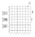
FIG. 12 is an example of creating a resolution-based data matrix. A data object 40 (e.g., a video, audio, or digital image file) is divided into a plurality of data segments 1-Y. For example, an image may be divided into sets of bits. A data segment of the plurality of data segments is then divided into data elements. For example, a mid-resolution pixel represented by 32 bits may be divided into four groups of 8-bit data elements. The first 8 bits corresponds to a low resolution pixel represented by 8 bits (i.e., a first resolution). Combining the first 8 bits with the second 8 bits, the third 8 bits, and the fourth 8 bits represents the mid-level resolution pixel represented by 32 bits (i.e., a second resolution). While this example depicts dividing the pixels of an image into data elements, any data segment of any data object (e.g., a video, audio, or digital image file) may be divided into a plurality of data elements. As an example, when the data object is a video file, a standard definition video file includes 480 lines per frame, while a high definition video file includes 720 or 1080 lines per frame. In one embodiment, a data segment may be divided into data elements where a first data element includes the 480 lines per frame and subsequent data elements include 720-480 or 1080-480 lines per frame, which are added to the 480 lines to produce the higher resolution video file. As a further example, audio files are sampled at a 44.1 KHz rate and multiples thereof or 48 KHz and multiples thereof. Lower sampling rates correspond to the first resolution and higher sampling rates correspond to the second resolution.
The data elements (i.e., groups of bits) are then arranged into a resolution-based data matrix (data matrix (D)). The data elements are arranged into the data matrix such that a first one or more rows of data elements corresponds to the data segment at the first resolution and the first one or more rows and a second one or more rows corresponds to the data segment at the second resolution. The first resolution includes a first fidelity level, and the second resolution includes a second fidelity level such that the second fidelity level is greater than the first fidelity level. For example, the first row of the data matrix contains the first 8 bits which correspond to the low resolution 8-bit representation of the pixel (i.e., the first resolution). The second row contains the second 8 bits, and the third row contains the third and fourth 8 bits. Combining the first, second, and third rows of the data matrix corresponds to the mid-level, 32-bit representation of the pixel (i.e., the second resolution).
FIG. 13 is another example of dispersed error encoding a data object based on resolution. The data segment divided into data elements and organized into the data matrix is dispersed error into a set of encoded data slices such that a first sub-set of encoded data slices of the set of encoded data slices corresponds to a first resolution of the data segment, a second sub-set of encoded data slices of the set of encoded data slices corresponds to a second resolution of the data segment, and a third sub-set of encoded data slices of the set of encoded data slices corresponds to redundancy encoded data slices. This is accomplished by matrix multiplying the data matrix with an encoding matrix (matrix (E)) to produce a coded matrix (matrix (C)). The first sub-set of encoded data slices is selected from a first one or more rows of the coded matrix, and the second sub-set of encoded data slices is selected to include the first one or more rows of the coded matrix and a second one or more rows of the coded matrix. In this example, EDS 1_1 is selected from the first row of the coded matrix containing the first 8 bits of the data segment. EDS 2_1 is selected from the second row of the coded matrix containing the second 8 bits of the data segment. EDS 3_1 is selected from the third row containing the third and fourth 8 bits of the data segment. EDS 4_1 is selected from row 4 of the coded matrix containing redundancy data X91-X92. EDS 5_1 is selected from row 5 of the coded matrix containing redundancy data X101-X-102. Therefore, a low resolution representation of the data segment may be obtained by retrieving EDS 1_1. If a computing device of the DSN requests retrieval of the data object at a higher resolution, more slices may be retrieved to enhance the image.
As another example, the data object 40 may be the result of a non-lossy transform such as a discrete cosine transform used as part of an image or audio file. The data object would be divided into a plurality of data segments and a data segment of the plurality of data segments would be divided into data elements in order from lower frequency to higher frequency. The data elements would be arranged in the data matrix such that obtaining a first encoded data slice would contain the lowest frequency information and would be a decent approximation of the original data on its own. Adding encoded data slices storing higher frequency oscillations would progressively improve the fidelity of the original data until the data is fully reconstructed.
In an example of a retrieval operation, when a computing device of the DSN determines the desired retrieval resolution of a data segment of data object is the first resolution, the computing device sends one or more first requests to one or more storage units of the DSN regarding the first sub-set of encoded data slices (e.g., EDS 1_1). Once the desired encoded data slices are retrieved, the computing device dispersed storage error decodes the first sub-set of encoded data slices to recover the data segment at the first resolution. For example, a low resolution representation of the data segment may be obtained by retrieving and decoding EDS 1_1. When the desired retrieval resolution is the second resolution, the computing device will send one or more second requests to storage units of the DSN regarding the second sub-set of encoded data slices (e.g., EDS 1_1, EDS 2_1, and EDS 3_1). The computing device will then dispersed storage error decode the second sub-set of encoded data slices to recover the data segment at the second resolution. Dispersed error encoding the data object produces redundant data (e.g., EDS 4_1 and EDS 5_1) so that desired encoded data slices may be reconstructed if lost or damaged. Rebuilding an encoded data slice is previously discussed in more detail with reference to FIG. 11.
FIG. 13A is another example of dispersed error encoding a data object based on resolution. The data segment divided into data elements may then be arranged into single column data matrix. Therefore, each row of the data matrix includes one data element of the data segment. In this example, the mid-level resolution pixel group representing by 32 bits is divided into data elements where each data element represents 8 bits. Each data element is arranged into a single column such that the data matrix contains one column and four rows. The first row of the data matrix includes data element D1 which is the low resolution pixel group representing by 8 bits (i.e., the first resolution). The second row of the data matrix includes data element D2, the third row of the data matrix includes data element D3, and the fourth row of the data matrix includes data element D4. Combining the first, second, third, and fourth rows of the data matrix corresponds to the mid-level resolution pixel group represented by 32 pixels (i.e., the second resolution).
The single column data matrix is dispersed error into a set of encoded data slices such that a first sub-set of encoded data slices of the set of encoded data slices corresponds to a first resolution of the data segment, a second sub-set of encoded data slices of the set of encoded data slices corresponds to a second resolution of the data segment, and a third sub-set of encoded data slices of the set of encoded data slices corresponds to redundancy encoded data slices. This is accomplished by matrix multiplying the data matrix with an encoding matrix (matrix (E)) to produce a coded matrix (matrix (C)). The first sub-set of encoded data slices is selected from a first one or more rows of the coded matrix, and the second sub-set of encoded data slices is selected to include the first one or more rows of the coded matrix and a second one or more rows of the coded matrix. In this example, EDS 1_1 is selected from the first row of the coded matrix containing the first 8 bits of the data segment. EDS 2_1 is selected from the second row of the coded matrix containing the second 8 bits of the data segment. EDS 3_1 is selected from the third row containing the third 8 bits of the data segment. EDS 4_1 is selected from the fourth row containing the fourth 8 bits of the data segment. EDS 5_1 is selected from the fifth row of the coded matrix containing redundancy data X111. EDS 6_1 is selected from the sixth row of the coded matrix containing redundancy data X121. Therefore, a low resolution representation of the data segment may be obtained by retrieving EDS 1_1. If a computing device of the DSN requests retrieval of the data object at a higher resolution, more slices may be retrieved to enhance the image.
FIG. 14 is a logic diagram of an example of a method of retrieving a data object at a desired retrieval resolution. The method begins with step 86 where a computing device of the DSN determines a desired retrieval resolution (e.g., res 1, res 2, or res 3) of a data segment of a data object. The data object (e.g., a video, audio, or digital image file) is divided into a plurality of data segments, where the data segment is dispersed error encoded into a set of encoded data slices. A first sub-set of encoded data slices of the set of encoded data slices corresponds to a first resolution of the data segment, a second sub-set of encoded data slices of the set of encoded data slices corresponds to a second resolution of the data segment, and a third sub-set of encoded data slices of the set of encoded data slices corresponds to redundancy encoded data slices. The first resolution includes a first fidelity level, and the second resolution includes a second fidelity level, wherein the second fidelity level is greater than the first fidelity level.
As discussed previously with reference to FIGS. 10-11, the first resolution of the data segments may correspond to a first grouping of pixels, and the second resolution of the data segments corresponds to a second grouping of pixels that includes the first grouping of pixels and additional pixels. As another example, an image file may be stored as a bitmap. The bitmap image may be interlaced and divided into data elements representing pixels located at coordinates (a+4k, b+4j) where k and j are integers, a and b are numbers 1 through 3, and each data element has a unique a and b combination (if a threshold of 16 slices is selected in order to recover the full image). The data elements would be arranged in the data matrix such that retrieving a first encoded data slice stored based on this encoding scheme would yield a thumbnail 1/16 the size of the full image. As more encoded data slices are retrieved, more of the full image may be retrieved.
As discussed previously with reference to FIGS. 11A-13A, the first resolution of the data segments may correspond to a first number of bits, and the second resolution of the data segments corresponds to a second number of bits that includes the first number of bits and additional bits. While image files are primarily discussed for simplicity, any data segment of any data object (e.g., a video, audio, or digital image file) may be divided into a plurality of data elements. As an example, when the data object is a video file, a standard definition video file includes 480 lines per frame, while a high definition video file includes 720 or 1080 lines per frame. In one embodiment, a data segment may be divided into data elements where a first data element includes the 480 lines per frame and subsequent data elements include 720-480 or 1080-480 lines per frame, which are added to the 480 lines to produce the higher resolution video file. As a further example, audio files are sampled at a 44.1 KHz rate and multiples thereof or 48 KHz and multiples thereof. Lower sampling rates correspond to the first resolution and higher sampling rates correspond to the second resolution.
As another example, the data object may be the result of a non-lossy transform such as a discrete cosine transform used as part of an image or audio file. The data object would be divided into a plurality of data segments and a data segment of the plurality of data segments would be divided into data elements in order from lower frequency to higher frequency. The data elements would be arranged in the data matrix such that obtaining a first encoded data slice would contain the lowest frequency information and would be a decent approximation of the original data on its own. Adding encoded data slices storing higher frequency oscillations would progressively improve the fidelity of the original data until the data is fully reconstructed.
When the computing device determines that the desired retrieval resolution is the first resolution, the method continues to step 88 where the computing device sends one or more first requests to one or more storage units of the DSN regarding the first sub-set of encoded data slices. In this example, the first sub-set of encoded data slices includes one encoded data slice (e.g., EDS 1_1 of FIGS. 11 and 13). The method then continues to step 90, where the computing device determines if EDS 1_1 is received within a given time period. When EDS 1_1 is received within the given time period, the method continues to step 92 where the computing device dispersed storage error decodes EDS 1_1 to recover the data segment at the first resolution.
When EDS 1_1 is not received within the given time period, the method continues to step 94 where the computing device rebuilds EDS 1_1. Rebuilding EDS 1_1 can be done by retrieving a decode threshold number of encoded data slices of the set of encoded data slices, dispersed storage error decoding the decode threshold number of encoded data slices to recapture a higher resolution data segment, dividing the higher resolution data segment into a plurality of data elements (as discussed in FIG. 10), matrix multiplying the data matrix with an encoding matrix to produce a coded matrix, and selecting a first row of the coded matrix as the rebuilt EDS 1_1. The computing device may then dispersed storage error decode the rebuilt EDS 1_1 to recover the data segment at the first resolution.
When the computing device determines at step 86 that the desired retrieval resolution is the second resolution, the method continues to step 96 where the computing device sends one or more second requests to storage units of the DSN regarding the second sub-set of encoded data slices. This flowchart depicts the example of FIG. 11 where EDS 1_1 and EDS 2_1 are the second sub-set of encoded data slices. The method then continues to step 98, where the computing device determines if EDS 1_1 or EDS 2_1 are received within a given time period. When EDS 1_1 and EDS 2_1 are received within the given time period, the method continues to step 100 where the computing device dispersed storage error decodes EDS 1_1 and EDS 2_1 to recover the data segment at the second resolution.
When either EDS 1_1 or EDS 2_1 is not received within the given time period, the method continues to step 102 where the computing device rebuilds the missing or damaged encoded data slice from other encoded data slices. Rebuilding EDS 1_1 or EDS 2_1 can be done by retrieving a decode threshold number of encoded data slices of the set of encoded data slices, dispersed storage error decoding the decode threshold number of encoded data slices to recapture a higher resolution data segment, dividing the higher resolution data segment into a plurality of data elements, matrix multiplying the data matrix with an encoding matrix to produce a coded matrix, and selecting a first row or a second row of the coded matrix as the rebuilt EDS 1_1 or EDS 2_1. The computing device may then dispersed storage error decode second sub-set of encoded data slices to recover the data segment at the second resolution.
When the computing device determines at step 86 that the desired retrieval resolution is the third resolution, the method continues to step 104 where the computing device sends one or more third requests to storage units of the DSN regarding a fourth sub-set of encoded data slices. This flowchart depicts the example of FIG. 11 where EDS 1_1 through EDS 5_1 are the fourth sub-set of encoded data slices corresponding to the third resolution. The method then continues to step 106, where the computing device determines if EDS 1_1 through EDS 5_1 are received within a given time period. When EDS 1_1 through EDS 5_1 are received within the given time period, the method continues to step 108 where the computing device dispersed storage error decodes EDS 1_1 through EDS 5_1 to recover the data segment at the third resolution.
When any of the slices EDS 1_1 through EDS 5_1 are not received within the given time period, the method continues to step 110 where the computing device rebuilds the missing or damaged encoded data slice from other encoded data slices. Rebuilding the lost or damaged encoded data slice can be done by retrieving a decode threshold number of encoded data slices of the set of encoded data slices, dispersed storage error decoding the decode threshold number of encoded data slices to recapture a higher resolution data segment, dividing the higher resolution data segment into a plurality of data elements, matrix multiplying the data matrix with an encoding matrix to produce a coded matrix, and selecting necessary row of the coded matrix as the rebuilt encoded data slice. The computing device may then dispersed storage error decode the third sub-set of encoded data slices to recover the data segment at the third resolution.
It is noted that terminologies as may be used herein such as bit stream, stream, signal sequence, etc. (or their equivalents) have been used interchangeably to describe digital information whose content corresponds to any of a number of desired types (e.g., data, video, speech, audio, etc. any of which may generally be referred to as ‘data’).
As may be used herein, the terms “substantially” and “approximately” provides an industry-accepted tolerance for its corresponding term and/or relativity between items. Such an industry-accepted tolerance ranges from less than one percent to fifty percent and corresponds to, but is not limited to, component values, integrated circuit process variations, temperature variations, rise and fall times, and/or thermal noise. Such relativity between items ranges from a difference of a few percent to magnitude differences. As may also be used herein, the term(s) “configured to”, “operably coupled to”, “coupled to”, and/or “coupling” includes direct coupling between items and/or indirect coupling between items via an intervening item (e.g., an item includes, but is not limited to, a component, an element, a circuit, and/or a module) where, for an example of indirect coupling, the intervening item does not modify the information of a signal but may adjust its current level, voltage level, and/or power level. As may further be used herein, inferred coupling (i.e., where one element is coupled to another element by inference) includes direct and indirect coupling between two items in the same manner as “coupled to”. As may even further be used herein, the term “configured to”, “operable to”, “coupled to”, or “operably coupled to” indicates that an item includes one or more of power connections, input(s), output(s), etc., to perform, when activated, one or more its corresponding functions and may further include inferred coupling to one or more other items. As may still further be used herein, the term “associated with”, includes direct and/or indirect coupling of separate items and/or one item being embedded within another item.
As may be used herein, the term “compares favorably”, indicates that a comparison between two or more items, signals, etc., provides a desired relationship. For example, when the desired relationship is that signal 1 has a greater magnitude than signal 2, a favorable comparison may be achieved when the magnitude of signal 1 is greater than that of signal 2 or when the magnitude of signal 2 is less than that of signal 1. As may be used herein, the term “compares unfavorably”, indicates that a comparison between two or more items, signals, etc., fails to provide the desired relationship.
As may also be used herein, the terms “processing module”, “processing circuit”, “processor”, and/or “processing unit” may be a single processing device or a plurality of processing devices. Such a processing device may be a microprocessor, micro-controller, digital signal processor, microcomputer, central processing unit, field programmable gate array, programmable logic device, state machine, logic circuitry, analog circuitry, digital circuitry, and/or any device that manipulates signals (analog and/or digital) based on hard coding of the circuitry and/or operational instructions. The processing module, module, processing circuit, and/or processing unit may be, or further include, memory and/or an integrated memory element, which may be a single memory device, a plurality of memory devices, and/or embedded circuitry of another processing module, module, processing circuit, and/or processing unit. Such a memory device may be a read-only memory, random access memory, volatile memory, non-volatile memory, static memory, dynamic memory, flash memory, cache memory, and/or any device that stores digital information. Note that if the processing module, module, processing circuit, and/or processing unit includes more than one processing device, the processing devices may be centrally located (e.g., directly coupled together via a wired and/or wireless bus structure) or may be distributedly located (e.g., cloud computing via indirect coupling via a local area network and/or a wide area network). Further note that if the processing module, module, processing circuit, and/or processing unit implements one or more of its functions via a state machine, analog circuitry, digital circuitry, and/or logic circuitry, the memory and/or memory element storing the corresponding operational instructions may be embedded within, or external to, the circuitry comprising the state machine, analog circuitry, digital circuitry, and/or logic circuitry. Still further note that, the memory element may store, and the processing module, module, processing circuit, and/or processing unit executes, hard coded and/or operational instructions corresponding to at least some of the steps and/or functions illustrated in one or more of the Figures. Such a memory device or memory element can be included in an article of manufacture.
One or more embodiments have been described above with the aid of method steps illustrating the performance of specified functions and relationships thereof. The boundaries and sequence of these functional building blocks and method steps have been arbitrarily defined herein for convenience of description. Alternate boundaries and sequences can be defined so long as the specified functions and relationships are appropriately performed. Any such alternate boundaries or sequences are thus within the scope and spirit of the claims. Further, the boundaries of these functional building blocks have been arbitrarily defined for convenience of description. Alternate boundaries could be defined as long as the certain significant functions are appropriately performed. Similarly, flow diagram blocks may also have been arbitrarily defined herein to illustrate certain significant functionality.
To the extent used, the flow diagram block boundaries and sequence could have been defined otherwise and still perform the certain significant functionality. Such alternate definitions of both functional building blocks and flow diagram blocks and sequences are thus within the scope and spirit of the claims. One of average skill in the art will also recognize that the functional building blocks, and other illustrative blocks, modules and components herein, can be implemented as illustrated or by discrete components, application specific integrated circuits, processors executing appropriate software and the like or any combination thereof.
In addition, a flow diagram may include a “start” and/or “continue” indication. The “start” and “continue” indications reflect that the steps presented can optionally be incorporated in or otherwise used in conjunction with other routines. In this context, “start” indicates the beginning of the first step presented and may be preceded by other activities not specifically shown. Further, the “continue” indication reflects that the steps presented may be performed multiple times and/or may be succeeded by other activities not specifically shown. Further, while a flow diagram indicates a particular ordering of steps, other orderings are likewise possible provided that the principles of causality are maintained.
The one or more embodiments are used herein to illustrate one or more aspects, one or more features, one or more concepts, and/or one or more examples. A physical embodiment of an apparatus, an article of manufacture, a machine, and/or of a process may include one or more of the aspects, features, concepts, examples, etc. described with reference to one or more of the embodiments discussed herein. Further, from figure to figure, the embodiments may incorporate the same or similarly named functions, steps, modules, etc. that may use the same or different reference numbers and, as such, the functions, steps, modules, etc. may be the same or similar functions, steps, modules, etc. or different ones.
Unless specifically stated to the contra, signals to, from, and/or between elements in a figure of any of the figures presented herein may be analog or digital, continuous time or discrete time, and single-ended or differential. For instance, if a signal path is shown as a single-ended path, it also represents a differential signal path. Similarly, if a signal path is shown as a differential path, it also represents a single-ended signal path. While one or more particular architectures are described herein, other architectures can likewise be implemented that use one or more data buses not expressly shown, direct connectivity between elements, and/or indirect coupling between other elements as recognized by one of average skill in the art.
The term “module” is used in the description of one or more of the embodiments. A module implements one or more functions via a device such as a processor or other processing device or other hardware that may include or operate in association with a memory that stores operational instructions. A module may operate independently and/or in conjunction with software and/or firmware. As also used herein, a module may contain one or more sub-modules, each of which may be one or more modules.
As may further be used herein, a computer readable memory includes one or more memory elements. A memory element may be a separate memory device, multiple memory devices, or a set of memory locations within a memory device. Such a memory device may be a read-only memory, random access memory, volatile memory, non-volatile memory, static memory, dynamic memory, flash memory, cache memory, and/or any device that stores digital information. The memory device may be in a form a solid state memory, a hard drive memory, cloud memory, thumb drive, server memory, computing device memory, and/or other physical medium for storing digital information.
While particular combinations of various functions and features of the one or more embodiments have been expressly described herein, other combinations of these features and functions are likewise possible. The present disclosure is not limited by the particular examples disclosed herein and expressly incorporates these other combinations.

Claims (16)

What is claimed is:
1. A method for execution by a computing device of a dispersed storage network (DSN), the method comprises:
determining a desired retrieval resolution of a data segment of a data object, wherein the data object is divided into a plurality of data segments, wherein the data segment is dispersed error encoded into a set of encoded data slices in accordance with a varying resolution scheme, wherein a first sub-set of encoded data slices of the set of encoded data slices corresponds to a first resolution of the data segment, a second sub-set of encoded data slices of the set of encoded data slices corresponds to a second resolution of the data segment, and a third sub-set of encoded data slices of the set of encoded data slices corresponds to redundancy encoded data slices;
when the desired retrieval resolution is the first resolution:
sending one or more first requests to one or more storage units of the DSN regarding the first sub-set of encoded data slices; and
dispersed storage error decoding the first sub-set of encoded data slices to recover the data segment at the first resolution; and
when the desired retrieval resolution is the second resolution:
sending one or more second requests to storage units of the DSN regarding the second sub-set of encoded data slices; and
dispersed storage error decoding the second sub-set of encoded data slices to recover the data segment at the second resolution.
2. The method of claim 1 further comprises:
when the desired retrieval resolution is a third resolution, wherein a fourth sub-set of encoded data slices of the set of encoded data slices corresponds to the third resolution of the data segment:
sending third requests to the storage units of the DSN regarding the fourth sub-set of encoded data slices; and
dispersed storage error decoding the fourth sub-set of encoded data slices to recover the data segment at the third resolution.
3. The method of claim 1, wherein the dispersed error encoding the data segment in accordance with the varying resolution scheme comprises:
dividing the data segment into a plurality of data elements;
arranging the data elements into a data matrix, wherein a first one or more rows of data elements corresponds to the data segment at the first resolution and the first one or more rows and a second one or more rows corresponds to the data segment at the second resolution;
matrix multiplying the data matrix with an encoding matrix to produce a coded matrix;
selecting the first sub-set of encoded data slices from a first one or more rows of the coded matrix; and
selecting the second sub-set of encoded data slices to include the first one or more rows of the coded matrix and a second one or more rows of the coded matrix.
4. The method of claim 1 further comprises:
sending a read request to a storage unit of the one or more storage units for a first encoded data slice of the set of encoded data slices when the first sub-set of encoded data slices includes one encoded data slice;
when the first encoded data slice is not received within a given time period, rebuilding the first encoded data slice by:
retrieving a decode threshold number of encoded data slices of the set of encoded data slices;
dispersed storage error decoding the decode threshold number of encoded data slices to recapture a higher resolution data segment;
dividing the higher resolution data segment into a plurality of data elements, wherein a first row of data elements corresponds to the data segment at the first resolution and other rows correspond to one or more higher resolutions of the data segment;
matrix multiplying the data matrix with an encoding matrix to produce a coded matrix;
selecting a first row of the coded matrix as the rebuilt first encoded data slice; and
dispersed storage error decoding the rebuilt first encoded data slice to recover the data segment at the first resolution.
5. The method of claim 1 further comprises:
the first resolution includes a first fidelity level; and
the second resolution includes a second fidelity level, wherein the second fidelity level is greater than the first fidelity level.
6. The method of claim 1, wherein the data object comprises one or more of:
a video file;
an audio file; and
a digital image file.
7. The method of claim 1 further comprises:
the first resolution of the data segments corresponds to a first number of bits; and
the second resolution of the data segments corresponds to a second number of bits that includes the first number of bits and additional bits.
8. The method of claim 1 further comprises:
the first resolution of the data segments corresponds to a first grouping of pixels; and
the second resolution of the data segments corresponds to a second grouping of pixels that includes the first grouping of pixels and additional pixels.
9. A computing device of a dispersed storage network (DSN), the computing device comprises:
an interface;
memory; and
a processing module operably coupled to the memory and the interface, wherein the processing module is operable to:
determine a desired retrieval resolution of a data segment of a data object, wherein the data object is divided into a plurality of data segments, wherein the data segment is dispersed error encoded into a set of encoded data slices in accordance with a varying resolution scheme, wherein a first sub-set of encoded data slices of the set of encoded data slices corresponds to a first resolution of the data segment, a second sub-set of encoded data slices of the set of encoded data slices corresponds to a second resolution of the data segment, and a third sub-set of encoded data slices of the set of encoded data slices corresponds to redundancy encoded data slices;
when the desired retrieval resolution is the first resolution:
send one or more first requests to one or more storage units of the DSN regarding the first sub-set of encoded data slices; and
dispersed storage error decode the first sub-set of encoded data slices to recover the data segment at the first resolution; and
when the desired retrieval resolution is the second resolution:
send one or more second requests to storage units of the DSN regarding the second sub-set of encoded data slices; and
dispersed storage error decode the second sub-set of encoded data slices to recover the data segment at the second resolution.
10. The computing device of claim 9, wherein the processing module further functions to:
when the desired retrieval resolution is a third resolution, wherein a fourth sub-set of encoded data slices of the set of encoded data slices corresponds to the third resolution of the data segment:
send third requests to the storage units of the DSN regarding the fourth sub-set of encoded data slices; and
dispersed storage error decode the fourth sub-set of encoded data slices to recover the data segment at the third resolution.
11. The computing device of claim 9, wherein the processing module dispersed error encodes the data segment in accordance with the varying resolution scheme by:
dividing the data segment into a plurality of data elements;
arranging the data elements into a data matrix, wherein a first one or more rows of data elements corresponds to the data segment at the first resolution and the first one or more rows and a second one or more rows corresponds to the data segment at the second resolution;
matrix multiplying the data matrix with an encoding matrix to produce a coded matrix;
selecting the first sub-set of encoded data slices from a first one or more rows of the coded matrix; and
selecting the second sub-set of encoded data slices to include the first one or more rows of the coded matrix and a second one or more rows of the coded matrix.
12. The computing device of claim 9, wherein the processing module further functions to:
send a read request to a storage unit of the one or more storage units for a first encoded data slice of the set of encoded data slices when the first sub-set of encoded data slices includes one encoded data slice;
when the first encoded data slice is not received within a given time period, rebuild the first encoded data slice by:
retrieving a decode threshold number of encoded data slices of the set of encoded data slices;
dispersed storage error decoding the decode threshold number of encoded data slices to recapture a higher resolution data segment;
dividing the higher resolution data segment into a plurality of data elements, wherein a first row of data elements corresponds to the data segment at the first resolution and other rows correspond to one or more higher resolutions of the data segment;
matrix multiplying the data matrix with an encoding matrix to produce a coded matrix;
selecting a first row of the coded matrix as the rebuilt first encoded data slice; and
dispersed storage error decoding the rebuilt first encoded data slice to recover the data segment at the first resolution.
13. The computing device of claim 9 further comprises:
the first resolution includes a first fidelity level; and
the second resolution includes a second fidelity level, wherein the second fidelity level is greater than the first fidelity level.
14. The computing device of claim 9, wherein the data object comprises one or more of:
a video file;
an audio file; and
a digital image file.
15. The computing device of claim 9 further comprises:
the first resolution of the data segments corresponds to a first number of bits; and
the second resolution of the data segments corresponds to a second number of bits that includes the first number of bits and additional bits.
16. The computing device of claim 9 further comprises:
the first resolution of the data segments corresponds to a first grouping of pixels; and
the second resolution of the data segments corresponds to a second grouping of pixels that includes the first grouping of pixels and additional pixels.
US15/335,838 2016-10-27 2016-10-27 Dispersed storage of error encoded data objects having multiple resolutions Expired - Fee Related US10481977B2 (en)

Priority Applications (1)

Application Number Priority Date Filing Date Title
US15/335,838 US10481977B2 (en) 2016-10-27 2016-10-27 Dispersed storage of error encoded data objects having multiple resolutions

Applications Claiming Priority (1)

Application Number Priority Date Filing Date Title
US15/335,838 US10481977B2 (en) 2016-10-27 2016-10-27 Dispersed storage of error encoded data objects having multiple resolutions

Publications (2)

Publication Number Publication Date
US20180121284A1 US20180121284A1 (en) 2018-05-03
US10481977B2 true US10481977B2 (en) 2019-11-19

Family

ID=62021466

Family Applications (1)

Application Number Title Priority Date Filing Date
US15/335,838 Expired - Fee Related US10481977B2 (en) 2016-10-27 2016-10-27 Dispersed storage of error encoded data objects having multiple resolutions

Country Status (1)

Country Link
US (1) US10481977B2 (en)

Families Citing this family (1)

* Cited by examiner, † Cited by third party
Publication number Priority date Publication date Assignee Title
US10567509B2 (en) * 2017-05-15 2020-02-18 International Business Machines Corporation Rebuilding derived content

Citations (82)

* Cited by examiner, † Cited by third party
Publication number Priority date Publication date Assignee Title
US4092732A (en) 1977-05-31 1978-05-30 International Business Machines Corporation System for recovering data stored in failed memory unit
US5454101A (en) 1992-09-15 1995-09-26 Universal Firmware Industries, Ltd. Data storage system with set lists which contain elements associated with parents for defining a logical hierarchy and general record pointers identifying specific data sets
US5485474A (en) 1988-02-25 1996-01-16 The President And Fellows Of Harvard College Scheme for information dispersal and reconstruction
US5774643A (en) 1995-10-13 1998-06-30 Digital Equipment Corporation Enhanced raid write hole protection and recovery
US5802364A (en) 1996-04-15 1998-09-01 Sun Microsystems, Inc. Metadevice driver rename/exchange technique for a computer system incorporating a plurality of independent device drivers
US5809285A (en) 1995-12-21 1998-09-15 Compaq Computer Corporation Computer system having a virtual drive array controller
US5890156A (en) 1996-05-02 1999-03-30 Alcatel Usa, Inc. Distributed redundant database
US5987622A (en) 1993-12-10 1999-11-16 Tm Patents, Lp Parallel computer system including parallel storage subsystem including facility for correction of data in the event of failure of a storage device in parallel storage subsystem
US5991414A (en) 1997-09-12 1999-11-23 International Business Machines Corporation Method and apparatus for the secure distributed storage and retrieval of information
US6012159A (en) 1996-01-17 2000-01-04 Kencast, Inc. Method and system for error-free data transfer
US6058454A (en) 1997-06-09 2000-05-02 International Business Machines Corporation Method and system for automatically configuring redundant arrays of disk memory devices
US6128277A (en) 1997-10-01 2000-10-03 California Inst Of Techn Reliable array of distributed computing nodes
US6175571B1 (en) 1994-07-22 2001-01-16 Network Peripherals, Inc. Distributed memory switching hub
US6256688B1 (en) 1997-12-02 2001-07-03 Casio Computer Co., Ltd. Interface apparatus operable by using floppy disk drive
US6272658B1 (en) 1997-10-27 2001-08-07 Kencast, Inc. Method and system for reliable broadcasting of data files and streams
US6301604B1 (en) 1997-12-01 2001-10-09 Matsushita Electric Industrial Co., Ltd. Multimedia server
US6356949B1 (en) 1999-01-29 2002-03-12 Intermec Ip Corp. Automatic data collection device that receives data output instruction from data consumer
US6366995B1 (en) 1998-08-19 2002-04-02 Acuid Corporation Limited System and a method for defining transforms of memory device addresses
US6374336B1 (en) 1997-12-24 2002-04-16 Avid Technology, Inc. Computer system and process for transferring multiple high bandwidth streams of data between multiple storage units and multiple applications in a scalable and reliable manner
US20020062422A1 (en) 2000-11-18 2002-05-23 International Business Machines Corporation Method for rebuilding meta-data in a data storage system and a data storage system
US6415373B1 (en) 1997-12-24 2002-07-02 Avid Technology, Inc. Computer system and process for transferring multiple high bandwidth streams of data between multiple storage units and multiple applications in a scalable and reliable manner
US6418539B1 (en) 1995-05-25 2002-07-09 Compaq Computer Corporation Continuously available computer memory systems
US20020166079A1 (en) 2001-01-29 2002-11-07 Ulrich Thomas R. Dynamic data recovery
US20030018927A1 (en) 2001-07-23 2003-01-23 Gadir Omar M.A. High-availability cluster virtual server system
US20030037261A1 (en) 2001-03-26 2003-02-20 Ilumin Corporation Secured content delivery system and method
US20030065617A1 (en) 2001-06-30 2003-04-03 Watkins Mark Robert Method of billing for utilization of a data storage array, and an array controller therefor
US20030084020A1 (en) 2000-12-22 2003-05-01 Li Shu Distributed fault tolerant and secure storage
US6571282B1 (en) 1999-08-31 2003-05-27 Accenture Llp Block-based communication in a communication services patterns environment
US6609223B1 (en) 1999-04-06 2003-08-19 Kencast, Inc. Method for packet-level fec encoding, in which on a source packet-by-source packet basis, the error correction contributions of a source packet to a plurality of wildcard packets are computed, and the source packet is transmitted thereafter
US20040024963A1 (en) 2002-08-05 2004-02-05 Nisha Talagala Method and system for striping data to accommodate integrity metadata
US6718361B1 (en) 2000-04-07 2004-04-06 Network Appliance Inc. Method and apparatus for reliable and scalable distribution of data files in distributed networks
US20040122917A1 (en) 2002-12-18 2004-06-24 Menon Jaishankar Moothedath Distributed storage system for data-sharing among client computers running defferent operating system types
US6785783B2 (en) 2000-11-30 2004-08-31 International Business Machines Corporation NUMA system with redundant main memory architecture
US20040215998A1 (en) 2003-04-10 2004-10-28 International Business Machines Corporation Recovery from failures within data processing systems
US20040228493A1 (en) 2003-05-14 2004-11-18 Kenneth Ma Method and system for disaster recovery of data from a storage device
US6826711B2 (en) 2000-02-18 2004-11-30 Avamar Technologies, Inc. System and method for data protection with multidimensional parity
US6879596B1 (en) 2001-04-11 2005-04-12 Applied Micro Circuits Corporation System and method for systolic array sorting of information segments
US20050100022A1 (en) 2003-11-12 2005-05-12 Ramprashad Sean A. Media delivery using quality of service differentiation within a media stream
US20050114594A1 (en) 2003-11-24 2005-05-26 Corbett Peter F. Semi-static distribution technique
US20050125593A1 (en) 2001-01-11 2005-06-09 Yotta Yotta, Inc. Storage virtualization system and methods
US20050132070A1 (en) 2000-11-13 2005-06-16 Redlich Ron M. Data security system and method with editor
US20050131993A1 (en) 2003-12-15 2005-06-16 Fatula Joseph J.Jr. Apparatus, system, and method for autonomic control of grid system resources
US20050144382A1 (en) 2003-12-29 2005-06-30 Schmisseur Mark A. Method, system, and program for managing data organization
US20050229069A1 (en) 2004-04-02 2005-10-13 Hitachi Global Storage Technologies Netherlands, B.V. Techniques for detecting and correcting errors using multiple interleave erasure pointers
US7003688B1 (en) 2001-11-15 2006-02-21 Xiotech Corporation System and method for a reserved memory area shared by all redundant storage controllers
US20060047907A1 (en) 2004-08-30 2006-03-02 Hitachi, Ltd. Storage system and a storage management system
US7024451B2 (en) 2001-11-05 2006-04-04 Hewlett-Packard Development Company, L.P. System and method for maintaining consistent independent server-side state among collaborating servers
US7024609B2 (en) 2001-04-20 2006-04-04 Kencast, Inc. System for protecting the transmission of live data streams, and upon reception, for reconstructing the live data streams and recording them into files
US20060136448A1 (en) 2004-12-20 2006-06-22 Enzo Cialini Apparatus, system, and method for database provisioning
US20060156059A1 (en) 2005-01-13 2006-07-13 Manabu Kitamura Method and apparatus for reconstructing data in object-based storage arrays
US7080101B1 (en) 2000-12-01 2006-07-18 Ncr Corp. Method and apparatus for partitioning data for storage in a database
US7103915B2 (en) 2000-11-13 2006-09-05 Digital Doors, Inc. Data security system and method
US7103824B2 (en) 2002-07-29 2006-09-05 Robert Halford Multi-dimensional data protection and mirroring method for micro level data
US20060224603A1 (en) 2005-04-05 2006-10-05 Wal-Mart Stores, Inc. System and methods for facilitating a linear grid database with data organization by dimension
US7140044B2 (en) 2000-11-13 2006-11-21 Digital Doors, Inc. Data security system and method for separation of user communities
US7146644B2 (en) 2000-11-13 2006-12-05 Digital Doors, Inc. Data security system and method responsive to electronic attacks
US7171493B2 (en) 2001-12-19 2007-01-30 The Charles Stark Draper Laboratory Camouflage of network traffic to resist attack
US20070079081A1 (en) 2005-09-30 2007-04-05 Cleversafe, Llc Digital data storage system
US20070079083A1 (en) 2005-09-30 2007-04-05 Gladwin S Christopher Metadata management system for an information dispersed storage system
US20070079082A1 (en) 2005-09-30 2007-04-05 Gladwin S C System for rebuilding dispersed data
US20070088970A1 (en) 2003-04-10 2007-04-19 Lenovo (Singapore) Pte.Ltd Recovery from failures within data processing systems
US7222133B1 (en) 2004-02-05 2007-05-22 Unisys Corporation Method for reducing database recovery time
US7240236B2 (en) 2004-03-23 2007-07-03 Archivas, Inc. Fixed content distributed data storage using permutation ring encoding
US20070174192A1 (en) 2005-09-30 2007-07-26 Gladwin S C Billing system for information dispersal system
US20070214285A1 (en) 2006-03-08 2007-09-13 Omneon Video Networks Gateway server
US7272613B2 (en) 2000-10-26 2007-09-18 Intel Corporation Method and system for managing distributed content and related metadata
US20070234110A1 (en) 2003-08-14 2007-10-04 Soran Philip E Virtual Disk Drive System and Method
US20070283167A1 (en) 2003-03-13 2007-12-06 Venters Carl V Iii Secure streaming container
US20090094251A1 (en) 2007-10-09 2009-04-09 Gladwin S Christopher Virtualized data storage vaults on a dispersed data storage network
US20090094318A1 (en) 2005-09-30 2009-04-09 Gladwin S Christopher Smart access to a dispersed data storage network
US7636724B2 (en) 2001-08-31 2009-12-22 Peerify Technologies LLC Data storage system and method by shredding and deshredding
US20100023524A1 (en) 2007-10-09 2010-01-28 Gladwin S Christopher Block based access to a dispersed data storage network
US20110213929A1 (en) * 2010-02-27 2011-09-01 Cleversafe, Inc. Data migration between a raid memory and a dispersed storage network memory
US20150355966A1 (en) * 2014-06-05 2015-12-10 Cleversafe, Inc. Verifying a status level of stored encoded data slices
US20160154698A1 (en) * 2014-12-02 2016-06-02 Cleversafe, Inc. Coordinating storage of data in dispersed storage networks
US20160253240A1 (en) * 2015-02-27 2016-09-01 International Business Machines Corporation Rebuilding encoded data slices in a dispersed storage network
US20170153828A1 (en) * 2015-11-30 2017-06-01 International Business Machines Corporation Proactively deselect storage units for access during major geographic events
US20170249205A1 (en) * 2016-02-29 2017-08-31 International Business Machines Corporation Issue escalation by management unit
US20180024887A1 (en) * 2014-01-31 2018-01-25 International Business Machines Corporation Writing encoded data slices in a dispersed storage network
US9927978B2 (en) * 2009-12-29 2018-03-27 International Business Machines Corporation Dispersed storage network (DSN) and system with improved security
US9934092B2 (en) * 2016-07-12 2018-04-03 International Business Machines Corporation Manipulating a distributed agreement protocol to identify a desired set of storage units
US20190138393A1 (en) * 2011-10-04 2019-05-09 International Business Machines Corporation Encoding data utilizing a zero information gain function

Patent Citations (88)

* Cited by examiner, † Cited by third party
Publication number Priority date Publication date Assignee Title
US4092732A (en) 1977-05-31 1978-05-30 International Business Machines Corporation System for recovering data stored in failed memory unit
US5485474A (en) 1988-02-25 1996-01-16 The President And Fellows Of Harvard College Scheme for information dispersal and reconstruction
US5454101A (en) 1992-09-15 1995-09-26 Universal Firmware Industries, Ltd. Data storage system with set lists which contain elements associated with parents for defining a logical hierarchy and general record pointers identifying specific data sets
US5987622A (en) 1993-12-10 1999-11-16 Tm Patents, Lp Parallel computer system including parallel storage subsystem including facility for correction of data in the event of failure of a storage device in parallel storage subsystem
US6175571B1 (en) 1994-07-22 2001-01-16 Network Peripherals, Inc. Distributed memory switching hub
US6418539B1 (en) 1995-05-25 2002-07-09 Compaq Computer Corporation Continuously available computer memory systems
US5774643A (en) 1995-10-13 1998-06-30 Digital Equipment Corporation Enhanced raid write hole protection and recovery
US5809285A (en) 1995-12-21 1998-09-15 Compaq Computer Corporation Computer system having a virtual drive array controller
US6012159A (en) 1996-01-17 2000-01-04 Kencast, Inc. Method and system for error-free data transfer
US5802364A (en) 1996-04-15 1998-09-01 Sun Microsystems, Inc. Metadevice driver rename/exchange technique for a computer system incorporating a plurality of independent device drivers
US5890156A (en) 1996-05-02 1999-03-30 Alcatel Usa, Inc. Distributed redundant database
US6058454A (en) 1997-06-09 2000-05-02 International Business Machines Corporation Method and system for automatically configuring redundant arrays of disk memory devices
US5991414A (en) 1997-09-12 1999-11-23 International Business Machines Corporation Method and apparatus for the secure distributed storage and retrieval of information
US6192472B1 (en) 1997-09-12 2001-02-20 International Business Machines Corporation Method and apparatus for the secure distributed storage and retrieval of information
US6128277A (en) 1997-10-01 2000-10-03 California Inst Of Techn Reliable array of distributed computing nodes
US6567948B2 (en) 1997-10-27 2003-05-20 Kencast, Inc. Method and system for reliable broadcasting of data files and streams
US6272658B1 (en) 1997-10-27 2001-08-07 Kencast, Inc. Method and system for reliable broadcasting of data files and streams
US6301604B1 (en) 1997-12-01 2001-10-09 Matsushita Electric Industrial Co., Ltd. Multimedia server
US6256688B1 (en) 1997-12-02 2001-07-03 Casio Computer Co., Ltd. Interface apparatus operable by using floppy disk drive
US6374336B1 (en) 1997-12-24 2002-04-16 Avid Technology, Inc. Computer system and process for transferring multiple high bandwidth streams of data between multiple storage units and multiple applications in a scalable and reliable manner
US6415373B1 (en) 1997-12-24 2002-07-02 Avid Technology, Inc. Computer system and process for transferring multiple high bandwidth streams of data between multiple storage units and multiple applications in a scalable and reliable manner
US6449688B1 (en) 1997-12-24 2002-09-10 Avid Technology, Inc. Computer system and process for transferring streams of data between multiple storage units and multiple applications in a scalable and reliable manner
US6785768B2 (en) 1997-12-24 2004-08-31 Avid Technology, Inc. Computer system and process for transferring streams of data between multiple storage units and multiple applications in a scalable and reliable manner
US6760808B2 (en) 1997-12-24 2004-07-06 Avid Technology, Inc. Computer system and process for transferring multiple high bandwidth streams of data between multiple storage units and multiple applications in a scalable and reliable manner
US7111115B2 (en) 1997-12-24 2006-09-19 Avid Technology, Inc. Computer system and process for transferring multiple high bandwidth streams of data between multiple storage units and multiple applications in a scalable and reliable manner
US6366995B1 (en) 1998-08-19 2002-04-02 Acuid Corporation Limited System and a method for defining transforms of memory device addresses
US6356949B1 (en) 1999-01-29 2002-03-12 Intermec Ip Corp. Automatic data collection device that receives data output instruction from data consumer
US6609223B1 (en) 1999-04-06 2003-08-19 Kencast, Inc. Method for packet-level fec encoding, in which on a source packet-by-source packet basis, the error correction contributions of a source packet to a plurality of wildcard packets are computed, and the source packet is transmitted thereafter
US6571282B1 (en) 1999-08-31 2003-05-27 Accenture Llp Block-based communication in a communication services patterns environment
US6826711B2 (en) 2000-02-18 2004-11-30 Avamar Technologies, Inc. System and method for data protection with multidimensional parity
US6718361B1 (en) 2000-04-07 2004-04-06 Network Appliance Inc. Method and apparatus for reliable and scalable distribution of data files in distributed networks
US7272613B2 (en) 2000-10-26 2007-09-18 Intel Corporation Method and system for managing distributed content and related metadata
US7140044B2 (en) 2000-11-13 2006-11-21 Digital Doors, Inc. Data security system and method for separation of user communities
US7103915B2 (en) 2000-11-13 2006-09-05 Digital Doors, Inc. Data security system and method
US7146644B2 (en) 2000-11-13 2006-12-05 Digital Doors, Inc. Data security system and method responsive to electronic attacks
US20050132070A1 (en) 2000-11-13 2005-06-16 Redlich Ron M. Data security system and method with editor
US20020062422A1 (en) 2000-11-18 2002-05-23 International Business Machines Corporation Method for rebuilding meta-data in a data storage system and a data storage system
US6785783B2 (en) 2000-11-30 2004-08-31 International Business Machines Corporation NUMA system with redundant main memory architecture
US7080101B1 (en) 2000-12-01 2006-07-18 Ncr Corp. Method and apparatus for partitioning data for storage in a database
US20030084020A1 (en) 2000-12-22 2003-05-01 Li Shu Distributed fault tolerant and secure storage
US20050125593A1 (en) 2001-01-11 2005-06-09 Yotta Yotta, Inc. Storage virtualization system and methods
US20020166079A1 (en) 2001-01-29 2002-11-07 Ulrich Thomas R. Dynamic data recovery
US20030037261A1 (en) 2001-03-26 2003-02-20 Ilumin Corporation Secured content delivery system and method
US6879596B1 (en) 2001-04-11 2005-04-12 Applied Micro Circuits Corporation System and method for systolic array sorting of information segments
US7024609B2 (en) 2001-04-20 2006-04-04 Kencast, Inc. System for protecting the transmission of live data streams, and upon reception, for reconstructing the live data streams and recording them into files
US20030065617A1 (en) 2001-06-30 2003-04-03 Watkins Mark Robert Method of billing for utilization of a data storage array, and an array controller therefor
US20030018927A1 (en) 2001-07-23 2003-01-23 Gadir Omar M.A. High-availability cluster virtual server system
US7636724B2 (en) 2001-08-31 2009-12-22 Peerify Technologies LLC Data storage system and method by shredding and deshredding
US7024451B2 (en) 2001-11-05 2006-04-04 Hewlett-Packard Development Company, L.P. System and method for maintaining consistent independent server-side state among collaborating servers
US7003688B1 (en) 2001-11-15 2006-02-21 Xiotech Corporation System and method for a reserved memory area shared by all redundant storage controllers
US7171493B2 (en) 2001-12-19 2007-01-30 The Charles Stark Draper Laboratory Camouflage of network traffic to resist attack
US7103824B2 (en) 2002-07-29 2006-09-05 Robert Halford Multi-dimensional data protection and mirroring method for micro level data
US20040024963A1 (en) 2002-08-05 2004-02-05 Nisha Talagala Method and system for striping data to accommodate integrity metadata
US20040122917A1 (en) 2002-12-18 2004-06-24 Menon Jaishankar Moothedath Distributed storage system for data-sharing among client computers running defferent operating system types
US20070283167A1 (en) 2003-03-13 2007-12-06 Venters Carl V Iii Secure streaming container
US20040215998A1 (en) 2003-04-10 2004-10-28 International Business Machines Corporation Recovery from failures within data processing systems
US20070088970A1 (en) 2003-04-10 2007-04-19 Lenovo (Singapore) Pte.Ltd Recovery from failures within data processing systems
US20040228493A1 (en) 2003-05-14 2004-11-18 Kenneth Ma Method and system for disaster recovery of data from a storage device
US20070234110A1 (en) 2003-08-14 2007-10-04 Soran Philip E Virtual Disk Drive System and Method
US20050100022A1 (en) 2003-11-12 2005-05-12 Ramprashad Sean A. Media delivery using quality of service differentiation within a media stream
US20050114594A1 (en) 2003-11-24 2005-05-26 Corbett Peter F. Semi-static distribution technique
US20050131993A1 (en) 2003-12-15 2005-06-16 Fatula Joseph J.Jr. Apparatus, system, and method for autonomic control of grid system resources
US20050144382A1 (en) 2003-12-29 2005-06-30 Schmisseur Mark A. Method, system, and program for managing data organization
US7222133B1 (en) 2004-02-05 2007-05-22 Unisys Corporation Method for reducing database recovery time
US7240236B2 (en) 2004-03-23 2007-07-03 Archivas, Inc. Fixed content distributed data storage using permutation ring encoding
US20050229069A1 (en) 2004-04-02 2005-10-13 Hitachi Global Storage Technologies Netherlands, B.V. Techniques for detecting and correcting errors using multiple interleave erasure pointers
US20060047907A1 (en) 2004-08-30 2006-03-02 Hitachi, Ltd. Storage system and a storage management system
US20060136448A1 (en) 2004-12-20 2006-06-22 Enzo Cialini Apparatus, system, and method for database provisioning
US20060156059A1 (en) 2005-01-13 2006-07-13 Manabu Kitamura Method and apparatus for reconstructing data in object-based storage arrays
US20060224603A1 (en) 2005-04-05 2006-10-05 Wal-Mart Stores, Inc. System and methods for facilitating a linear grid database with data organization by dimension
US20070079081A1 (en) 2005-09-30 2007-04-05 Cleversafe, Llc Digital data storage system
US20070174192A1 (en) 2005-09-30 2007-07-26 Gladwin S C Billing system for information dispersal system
US20070079082A1 (en) 2005-09-30 2007-04-05 Gladwin S C System for rebuilding dispersed data
US20090094318A1 (en) 2005-09-30 2009-04-09 Gladwin S Christopher Smart access to a dispersed data storage network
US20070079083A1 (en) 2005-09-30 2007-04-05 Gladwin S Christopher Metadata management system for an information dispersed storage system
US20070214285A1 (en) 2006-03-08 2007-09-13 Omneon Video Networks Gateway server
US20090094251A1 (en) 2007-10-09 2009-04-09 Gladwin S Christopher Virtualized data storage vaults on a dispersed data storage network
US20100023524A1 (en) 2007-10-09 2010-01-28 Gladwin S Christopher Block based access to a dispersed data storage network
US9927978B2 (en) * 2009-12-29 2018-03-27 International Business Machines Corporation Dispersed storage network (DSN) and system with improved security
US20110213929A1 (en) * 2010-02-27 2011-09-01 Cleversafe, Inc. Data migration between a raid memory and a dispersed storage network memory
US20190138393A1 (en) * 2011-10-04 2019-05-09 International Business Machines Corporation Encoding data utilizing a zero information gain function
US20180024887A1 (en) * 2014-01-31 2018-01-25 International Business Machines Corporation Writing encoded data slices in a dispersed storage network
US20150355966A1 (en) * 2014-06-05 2015-12-10 Cleversafe, Inc. Verifying a status level of stored encoded data slices
US20160154698A1 (en) * 2014-12-02 2016-06-02 Cleversafe, Inc. Coordinating storage of data in dispersed storage networks
US20160253240A1 (en) * 2015-02-27 2016-09-01 International Business Machines Corporation Rebuilding encoded data slices in a dispersed storage network
US20170153828A1 (en) * 2015-11-30 2017-06-01 International Business Machines Corporation Proactively deselect storage units for access during major geographic events
US20170249205A1 (en) * 2016-02-29 2017-08-31 International Business Machines Corporation Issue escalation by management unit
US9934092B2 (en) * 2016-07-12 2018-04-03 International Business Machines Corporation Manipulating a distributed agreement protocol to identify a desired set of storage units

Non-Patent Citations (18)

* Cited by examiner, † Cited by third party
Title
Chung; An Automatic Data Segmentation Method for 3D Measured Data Points; National Taiwan University; pp. 1-8; 1998.
Harrison; Lightweight Directory Access Protocol (LDAP): Authentication Methods and Security Mechanisms; IETF Network Working Group; RFC 4513; Jun. 2006; pp. 1-32.
Kubiatowicz, et al.; OceanStore: An Architecture for Global-Scale Persistent Storage; Proceedings of the Ninth International Conference on Architectural Support for Programming Languages and Operating Systems (ASPLOS 2000); Nov. 2000; pp. 1-12.
Legg; Lightweight Directory Access Protocol (LDAP): Syntaxes and Matching Rules; IETF Network Working Group; RFC 4517; Jun. 2006; pp. 1-50.
Plank, T1: Erasure Codes for Storage Applications; FAST2005, 4th Usenix Conference on File Storage Technologies; Dec. 13-16, 2005; pp. 1-74.
Rabin; Efficient Dispersal of Information for Security, Load Balancing, and Fault Tolerance; Journal of the Association for Computer Machinery; vol. 36, No. 2; Apr. 1989; pp. 335-348.
Satran, et al.; Internet Small Computer Systems Interface (iSCSI); IETF Network Working Group; RFC 3720; Apr. 2004; pp. 1-257.
Sciberras; Lightweight Directory Access Protocol (LDAP): Schema for User Applications; IETF Network Working Group; RFC 4519; Jun. 2006; pp. 1-33.
Sermersheim; Lightweight Directory Access Protocol (LDAP): The Protocol; IETF Network Working Group; RFC 4511; Jun. 2006; pp. 1-68.
Shamir; How to Share a Secret; Communications of the ACM; vol. 22, No. 11; Nov. 1979; pp. 612-613.
Smith; Lightweight Directory Access Protocol (LDAP): String Representation of Search Filters; IETF Network Working Group; RFC 4515; Jun. 2006; pp. 1-12.
Smith; Lightweight Directory Access Protocol (LDAP): Uniform Resource Locator; IETF Network Working Group; RFC 4516; Jun. 2006; pp. 1-15.
Wildi; Java iSCSi Initiator; Master Thesis; Department of Computer and Information Science, University of Konstanz; Feb. 2007; 60 pgs.
Xin, et al.; Evaluation of Distributed Recovery in Large-Scale Storage Systems; 13th IEEE International Symposium on High Performance Distributed Computing; Jun. 2004; pp. 172-181.
Zeilenga; Lightweight Directory Access Protocol (LDAP): Directory Information Models; IETF Network Working Group; RFC 4512; Jun. 2006; pp. 1-49.
Zeilenga; Lightweight Directory Access Protocol (LDAP): Internationalized String Preparation; IETF Network Working Group; RFC 4518; Jun. 2006; pp. 1-14.
Zeilenga; Lightweight Directory Access Protocol (LDAP): String Representation of Distinguished Names; IETF Network Working Group; RFC 4514; Jun. 2006; pp. 1-15.
Zeilenga; Lightweight Directory Access Protocol (LDAP): Technical Specification Road Map; IETF Network Working Group; RFC 4510; Jun. 2006; pp. 1-8.

Also Published As

Publication number Publication date
US20180121284A1 (en) 2018-05-03

Similar Documents

Publication Publication Date Title
US10430277B2 (en) Multi option rebuilding in a dispersed storage network
US10171111B2 (en) Generating additional slices based on data access frequency
US10061648B2 (en) Efficient method for redundant storage of a set of encoded data slices
US20190243554A1 (en) Recovering data copies in a dispersed storage network
US11210151B1 (en) Peer-assisted data rebuilding
US20170249212A1 (en) Maximizing redundant information in a mirrored vault
US10298683B2 (en) Consolidating data access in a dispersed storage network
US10296404B2 (en) Determining slices used in a reconstruction
US10606700B2 (en) Enhanced dispersed storage error encoding using multiple encoding layers
US10042577B2 (en) Storing and retrieving mutable objects
US9875158B2 (en) Slice storage in a dispersed storage network
US10104168B2 (en) Method for managing throughput in a distributed storage network
US11157362B2 (en) Elastic storage in a dispersed storage network
US10067822B2 (en) Combined slice objects in alternate memory locations
US11153384B2 (en) Rebuilding derived content
US10481977B2 (en) Dispersed storage of error encoded data objects having multiple resolutions
US11463420B1 (en) Storage unit partial task processing
US10447471B2 (en) Systematic secret sharing
US10523241B2 (en) Object fan out write operation
US20180052735A1 (en) Efficient, secure, storage of meaningful content as part of a dsn memory
US20180060174A1 (en) Multiplying width and threshold for improved performance and efficiency
US20170003915A1 (en) Retrieving data in a dispersed storage network
US10409678B2 (en) Self-optimizing read-ahead
US10585751B2 (en) Partial rebuild operation within a dispersed storage network including local memory and cloud-based alternative memory
US9891995B2 (en) Cooperative decentralized rebuild scanning

Legal Events

Date Code Title Description
AS Assignment

Owner name: INTERNATIONAL BUSINESS MACHINES CORPORATION, NEW Y

Free format text: ASSIGNMENT OF ASSIGNORS INTEREST;ASSIGNOR:VOSSBERG, TREVOR J.;REEL/FRAME:040150/0493

Effective date: 20161019

STPP Information on status: patent application and granting procedure in general

Free format text: NON FINAL ACTION MAILED

STPP Information on status: patent application and granting procedure in general

Free format text: RESPONSE TO NON-FINAL OFFICE ACTION ENTERED AND FORWARDED TO EXAMINER

STPP Information on status: patent application and granting procedure in general

Free format text: NOTICE OF ALLOWANCE MAILED -- APPLICATION RECEIVED IN OFFICE OF PUBLICATIONS

STCF Information on status: patent grant

Free format text: PATENTED CASE

FEPP Fee payment procedure

Free format text: MAINTENANCE FEE REMINDER MAILED (ORIGINAL EVENT CODE: REM.); ENTITY STATUS OF PATENT OWNER: LARGE ENTITY

LAPS Lapse for failure to pay maintenance fees

Free format text: PATENT EXPIRED FOR FAILURE TO PAY MAINTENANCE FEES (ORIGINAL EVENT CODE: EXP.); ENTITY STATUS OF PATENT OWNER: LARGE ENTITY

STCH Information on status: patent discontinuation

Free format text: PATENT EXPIRED DUE TO NONPAYMENT OF MAINTENANCE FEES UNDER 37 CFR 1.362

FP Lapsed due to failure to pay maintenance fee

Effective date: 20231119