US10473097B2 - System and method for speed control of variable speed pumping systems - Google Patents
System and method for speed control of variable speed pumping systems Download PDFInfo
- Publication number
- US10473097B2 US10473097B2 US14/843,377 US201514843377A US10473097B2 US 10473097 B2 US10473097 B2 US 10473097B2 US 201514843377 A US201514843377 A US 201514843377A US 10473097 B2 US10473097 B2 US 10473097B2
- Authority
- US
- United States
- Prior art keywords
- speed
- motor
- value
- pump
- control signal
- Prior art date
- Legal status (The legal status is an assumption and is not a legal conclusion. Google has not performed a legal analysis and makes no representation as to the accuracy of the status listed.)
- Active, expires
Links
- 238000005086 pumping Methods 0.000 title claims abstract description 13
- 238000000034 method Methods 0.000 title abstract description 40
- 230000008569 process Effects 0.000 abstract description 10
- XLYOFNOQVPJJNP-UHFFFAOYSA-N water Substances O XLYOFNOQVPJJNP-UHFFFAOYSA-N 0.000 description 5
- 238000004364 calculation method Methods 0.000 description 4
- 238000006243 chemical reaction Methods 0.000 description 4
- 239000012530 fluid Substances 0.000 description 2
- VNWKTOKETHGBQD-UHFFFAOYSA-N methane Chemical compound C VNWKTOKETHGBQD-UHFFFAOYSA-N 0.000 description 2
- 230000010355 oscillation Effects 0.000 description 2
- 230000009466 transformation Effects 0.000 description 2
- 230000001131 transforming effect Effects 0.000 description 2
- CYTYCFOTNPOANT-UHFFFAOYSA-N Perchloroethylene Chemical compound ClC(Cl)=C(Cl)Cl CYTYCFOTNPOANT-UHFFFAOYSA-N 0.000 description 1
- 238000009825 accumulation Methods 0.000 description 1
- 230000033228 biological regulation Effects 0.000 description 1
- 230000008859 change Effects 0.000 description 1
- 238000012777 commercial manufacturing Methods 0.000 description 1
- 238000004590 computer program Methods 0.000 description 1
- 238000001816 cooling Methods 0.000 description 1
- 230000007423 decrease Effects 0.000 description 1
- 230000006872 improvement Effects 0.000 description 1
- 239000004973 liquid crystal related substance Substances 0.000 description 1
- 238000012986 modification Methods 0.000 description 1
- 230000004048 modification Effects 0.000 description 1
- 239000003345 natural gas Substances 0.000 description 1
- 239000003921 oil Substances 0.000 description 1
- 230000004044 response Effects 0.000 description 1
- 230000004043 responsiveness Effects 0.000 description 1
- 239000002002 slurry Substances 0.000 description 1
- 230000009182 swimming Effects 0.000 description 1
Images


Classifications
-
- F—MECHANICAL ENGINEERING; LIGHTING; HEATING; WEAPONS; BLASTING
- F04—POSITIVE - DISPLACEMENT MACHINES FOR LIQUIDS; PUMPS FOR LIQUIDS OR ELASTIC FLUIDS
- F04B—POSITIVE-DISPLACEMENT MACHINES FOR LIQUIDS; PUMPS
- F04B49/00—Control, e.g. of pump delivery, or pump pressure of, or safety measures for, machines, pumps, or pumping installations, not otherwise provided for, or of interest apart from, groups F04B1/00 - F04B47/00
- F04B49/06—Control using electricity
- F04B49/065—Control using electricity and making use of computers
-
- F—MECHANICAL ENGINEERING; LIGHTING; HEATING; WEAPONS; BLASTING
- F04—POSITIVE - DISPLACEMENT MACHINES FOR LIQUIDS; PUMPS FOR LIQUIDS OR ELASTIC FLUIDS
- F04B—POSITIVE-DISPLACEMENT MACHINES FOR LIQUIDS; PUMPS
- F04B1/00—Multi-cylinder machines or pumps characterised by number or arrangement of cylinders
- F04B1/12—Multi-cylinder machines or pumps characterised by number or arrangement of cylinders having cylinder axes coaxial with, or parallel or inclined to, main shaft axis
- F04B1/26—Control
-
- F—MECHANICAL ENGINEERING; LIGHTING; HEATING; WEAPONS; BLASTING
- F04—POSITIVE - DISPLACEMENT MACHINES FOR LIQUIDS; PUMPS FOR LIQUIDS OR ELASTIC FLUIDS
- F04B—POSITIVE-DISPLACEMENT MACHINES FOR LIQUIDS; PUMPS
- F04B23/00—Pumping installations or systems
- F04B23/04—Combinations of two or more pumps
-
- G—PHYSICS
- G05—CONTROLLING; REGULATING
- G05B—CONTROL OR REGULATING SYSTEMS IN GENERAL; FUNCTIONAL ELEMENTS OF SUCH SYSTEMS; MONITORING OR TESTING ARRANGEMENTS FOR SUCH SYSTEMS OR ELEMENTS
- G05B11/00—Automatic controllers
- G05B11/01—Automatic controllers electric
- G05B11/36—Automatic controllers electric with provision for obtaining particular characteristics, e.g. proportional, integral, differential
- G05B11/38—Automatic controllers electric with provision for obtaining particular characteristics, e.g. proportional, integral, differential for obtaining a proportional characteristic
-
- G—PHYSICS
- G05—CONTROLLING; REGULATING
- G05B—CONTROL OR REGULATING SYSTEMS IN GENERAL; FUNCTIONAL ELEMENTS OF SUCH SYSTEMS; MONITORING OR TESTING ARRANGEMENTS FOR SUCH SYSTEMS OR ELEMENTS
- G05B11/00—Automatic controllers
- G05B11/01—Automatic controllers electric
- G05B11/36—Automatic controllers electric with provision for obtaining particular characteristics, e.g. proportional, integral, differential
- G05B11/42—Automatic controllers electric with provision for obtaining particular characteristics, e.g. proportional, integral, differential for obtaining a characteristic which is both proportional and time-dependent, e.g. P. I., P. I. D.
-
- H—ELECTRICITY
- H02—GENERATION; CONVERSION OR DISTRIBUTION OF ELECTRIC POWER
- H02P—CONTROL OR REGULATION OF ELECTRIC MOTORS, ELECTRIC GENERATORS OR DYNAMO-ELECTRIC CONVERTERS; CONTROLLING TRANSFORMERS, REACTORS OR CHOKE COILS
- H02P23/00—Arrangements or methods for the control of AC motors characterised by a control method other than vector control
- H02P23/0004—Control strategies in general, e.g. linear type, e.g. P, PI, PID, using robust control
-
- F—MECHANICAL ENGINEERING; LIGHTING; HEATING; WEAPONS; BLASTING
- F04—POSITIVE - DISPLACEMENT MACHINES FOR LIQUIDS; PUMPS FOR LIQUIDS OR ELASTIC FLUIDS
- F04B—POSITIVE-DISPLACEMENT MACHINES FOR LIQUIDS; PUMPS
- F04B2203/00—Motor parameters
- F04B2203/02—Motor parameters of rotating electric motors
- F04B2203/0209—Rotational speed
Definitions
- the present invention relates to systems and methods for controlling pumping systems.
- the present invention relates to a system and method for speed control of variable speed water pumping systems.
- Pumping systems serve a wide range of applications.
- pumps may be used for pumping oil and natural gas, slurries, and most commonly water.
- Water pumps may be used for cooling towers, residential water supplies, and industrial and commercial manufacturing.
- water pumping systems are controlled with a proportional-integral-derivative (“PID”) controller.
- PID controller calculates an error between a system variable and a desired value of the system variable. The PID controller then attempts to minimize this error by manipulating a set of control parameters.
- the set of control parameters includes a proportional parameter, an integral parameter, and a derivative parameter. More commonly, these parameters are described in terms of time where the proportional parameter depends on the present error, the integral parameter depends on the accumulation of past errors, and the derivative parameter is a prediction of future errors, based on a current rate of change. These parameters are summed and used to adjust the process via a system control such as a control valve, a damper, or supplied power.
- a system control such as a control valve, a damper, or supplied power.
- the response of a PID controller is typically described in terms of responsiveness to an error, the degree of overshoot of the desired value, and the degree of system oscillation.
- PID controllers do not provide optimal control because they rely on a constant set of proportional, integral, and derivative parameters. Further, PID controllers, perform poorly when the PID loop gains must be reduced which leads to overshoot or oscillation of the desired value.
- U.S. Pat. No. 8,564,233 to Kidd et al. discloses a variable frequency drive system and a method of controlling a pump driven by a motor with the pump in a fluid system wherein the controller includes software executed by a digital signal processor or a microprocessor and performs classical PID control including soft-start, speed regulation, and motor protection.
- the controller relies on known PID control methods which are still susceptible to frequent overshoot.
- U.S. Pat. No. 8,801,389 to Stiles discloses a variable-speed pumping system including a pump, a motor coupled to the pump, and a computer controller with a variable speed drive.
- the controller calculates a difference value between the reference flow rate and the present flow rate and uses integral, proportional, or derivative control to generate a second motor speed based on the difference value.
- the system is designed for use as a multi-purpose controller for swimming pools having different pump requirements.
- Kidd the system in Stiles requires use of traditional PID control methods and is susceptible to the aforementioned problems.
- U.S. Pat. No. 8,760,089 to Smith discloses a control system for driving a pump motor at a variable speed with a control system including a rectifier, a controller on a power supply providing variable frequency power based upon switching signals provided by the controller.
- Proportional-integral derivative parameters for control algorithms control the pump unit.
- the system is designed mainly for use in open systems where a supply pump provides variable fluid per pressure tank.
- PID parameters in Smith leads to the same previously described problems of Kidd and Stiles.
- the prior art fails to disclose or suggest a system and method for controlling a pump motor speed by calculating a proportional value from a polynomial equation and generating a motor control signal from the proportional value. Therefore, there is a need in the art for a system and method that provides benefits above prior art PID control methods for pumping systems, including quick approach to a set point, reduced overshoot, easier tuning, easier controlling of the deadband and improved resistance to instability when compared to prior art systems and methods. By limiting the user inputs to a defined predetermined range, the system and method also decreases the chance of a bad user input that causes an interruption in the operation of the system.
- a system and method for controlling a speed of a pumping system includes a controller, a variable frequency drive connected to the controller, a motor connected to the variable frequency drive, a pump connected to the motor, a set of sensors connected to the motor, the pump, and the controller, and an interface connected to the controller.
- the controller includes a processor and a memory connected to the processor.
- a motor control process is saved in the memory and executed by the processor that generates a motor control signal to control the speed of the motor and the pump.
- the controller is connected to a set of pump systems, each includes a variable frequency drive, a motor connected to the frequency drive, a pump connected to the motor, and a set of sensors connected to the motor, the pump, and the controller.
- the motor control process receives a set of constants from the interface, measures an instantaneous pressure from the set of sensors, calculates a proportional value based on the set of constants and the instantaneous pressure, determines the motor control signal from the proportional value.
- the motor control signal is sent to the variable frequency drive which adjusts the speed of the motor based on the motor control signal.
- the described embodiments disclose significantly more than an abstract idea including technical advancements in the fields of pumps, motors, and data processing that includes a transformation of data which is directly related to real world objects and situations.
- FIG. 1A is a schematic of a pump system of a preferred embodiment.
- FIG. 1B is a schematic of a pump system of a preferred embodiment.
- FIG. 2 is a flowchart of a method for generating a pump motor control signal of a preferred embodiment.
- FIG. 3 is a flowchart of a method for determining a new motor speed of a preferred embodiment.
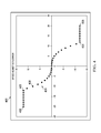
- FIG. 4 is a graph of a pump motor speed control signal of a preferred embodiment.
- FIGS. 5A-5F is an example of preferred code to generate a motor speed control signal of a preferred embodiment.
- aspects of the present disclosure may be illustrated and described in any of a number of patentable classes or contexts including any new and useful process or machine or any new and useful improvement.
- aspects of the present disclosure may be implemented entirely in hardware, entirely in software (including firmware, resident software, micro-code, etc.) or combining software and hardware implementation that may all generally be referred to herein as a “circuit,” “module,” “component,” or “system.”
- aspects of the present disclosure may take the form of a computer program product embodied in one or more computer readable media having computer readable program code embodied thereon.
- system 100 includes controller 101 connected to variable frequency drive 102 .
- Variable frequency drive 102 is connected to motor 103 .
- Motor 103 is connected to pump 104 .
- Set of sensors 105 is connected to pump 104 , motor 103 , and controller 101 .
- Interface 109 is connected to controller 101 .
- Controller 101 includes processor 106 and memory 107 connected to processor 106 .
- Control process 108 is saved in memory 107 and executed by processor 106 .
- control process 108 includes a set of conversion calculations 110 to convert data.
- set of conversions includes a conversion of flow rate to pressure and vice versa.
- Other conversion calculations known in the art may be employed.
- controller 101 is a programmable logic controller (“PLC”) model number ELC2-PB14NNDR available from Eaton Corporation.
- controller 101 is an E-Series Mark V PLC available from Tigerflow Systems, LLC. Controller 101 receives sensor data from set of sensors 105 , receives user input from interface 109 , and sends a motor control signal in the form of motor speed commands to variable frequency drive 102 based on sensor data from set of sensors 105 and based on user inputs from interface 109 .
- PLC programmable logic controller
- variable frequency drive 102 is an A1000 drive available from Yaskawa America, Inc. In another embodiment, variable frequency drive 102 is a VLT® AQUA Drive FC 202 drive available from Danfoss Power Solutions Company. Other suitable drives known in the art may be employed. Variable frequency drive 102 receives motor speed commands from controller 101 and sends alternating current (“AC”) power to motor 103 based on the motor speed commands.
- AC alternating current
- motor 103 is a NEMA Premium XRI Efficiency motor model no. MTRE654 available from Yaskawa America, Inc. Other suitable motors known in the art may be employed. Motor 103 receives AC power from variable frequency drive 102 and provides torque to pump 104 .
- variable frequency drive 102 and motor 103 is an integrated unit.
- the integrated unit is a VLT® DriveMotor FCM 300 available from Danfoss Power Solutions Company. Other suitable integrated drives and motors known in the art may be employed.
- pump 104 is a PAH-2 pump available from Danfoss Power Solutions Company. Other suitable pumps known in the art may be employed. Pump 104 receives torque from motor 103 and generates hydraulic power based on the torque.
- set of sensors 105 includes a pressure sensor and a speed sensor.
- the pressure sensor is a 200 series flow sensor available from Data Industrial.
- the pressure sensor is connected to a 310 series flow rate transmitter available from Data Industrial to provide flow rate data to controller 101 .
- Other suitable sensors and sensor-transmitter combinations known in the art may be employed.
- the motor speed sensor is an NPN AC motor speed sensor part no. OMDC-PU-40R available from OMEGA Engineering Inc.
- variable frequency drive 102 senses the motor speed.
- Set of sensors 105 generates sensor data that includes pressure data measured from pump 104 and motor speed data measured from motor 103 , and set of sensors 105 sends the sensor data to controller 101 .
- interface 109 is a liquid crystal display (“LCD”) touchscreen.
- Interface 109 receives user inputs that include one or more constants and displays user outputs that include the one or more constants.
- control process 108 calculates an operational speed for motor 103 , and thereby pump 104 , on open and closed loop pumping systems, based on a polynomial equation, as will be further described below.
- control process 108 calculates an instantaneous difference between a measured pressure and a pressure set point. This value is then used in the polynomial equation to calculate a proportional value.
- the constants of the polynomial equation are provided by a user input via interface 109 . The calculation is performed at set time intervals also defined by a user input. The proportional value is used to determine the operational speed and adjust the operational speed.
- system 111 includes controller 101 connected to a set of pump systems 112 .
- each pump system 112 includes variable frequency drive 102 connected to controller 101 , motor 103 connected to variable frequency drive 102 , pump 104 connected to motor 103 , and set of sensors 105 connected to pump 104 , motor 103 , and controller 101 .
- each of systems 100 and 111 has numerous configurations each of which is customized to suit the needs of an end user.
- each of systems 100 and 111 optionally includes any number of additional valves, sensors, controllers, supervisory control and data acquisition (“SCADA”) systems and software as desired.
- SCADA supervisory control and data acquisition
- control process 108 will be further described as method 200 for generating a control signal for a pump motor.
- a set of constants and a predetermined range are determined from user input and saved into memory.
- the set of constants include a gain, a pressure setpoint, a deadband, and a time interval between calculations of the proportional value.
- the predetermined range includes a positive limit and a negative limit for the proportional value. Once received, the time interval starts.
- a pressure set point is retrieved from memory.
- an instantaneous pressure is measured.
- a proportional value is calculated by the following polynomial equation:
- PV Gain ⁇ [ [ ( p instant - p setpoint p setpoint ) ⁇ 100 ] 3 ] + 100 deadband ⁇ [ ( p instant - p setpoint p setpoint ) ⁇ 100 ] - 100
- PV the proportional value
- p setpoint is the pressure set point
- p instant is the instantaneous pressure
- Gain, deadband are the gain and the deadband from the set of constants input by a user via an interface.
- the proportional value is compared to a predetermined range to determine whether the proportional value is within the predetermined range, i.e., whether the proportional value is less than or equal to a positive limit of the predetermined range and greater than or equal to a negative limit of the predetermined range.
- the proportional value is set as a pump speed adjustment value if the proportional value within the predetermined range, i.e., the proportional value is less than or equal to the positive limit and greater than or equal to the negative limit.
- the positive limit or the negative limit is set as the pump motor speed adjustment value. If the proportional value is greater than the positive limit, then the positive limit is set as the pump motor speed adjustment value. If the proportional value is less than the negative limit, then the negative limit is set as the pump motor speed adjustment value.
- a new motor speed command is determined from the speed adjustment value.
- the new motor speed command is sent to the variable frequency drive from a set of outputs, each of which corresponds to a pump as the new motor speed command signal.
- the variable frequency drive adjusts the motor speed by sending AC power to the motor at a voltage and a frequency based on the new motor speed command.
- the motor turns as a result of the applied voltage and frequency.
- the pump turns at the same speed as the motor and the pump adds or reduces hydraulic power in terms of pressure and flow.
- a stop command is determined. If a stop command has not been received, then method 200 proceeds to step 212 . At step 212 , whether the time interval has ended is determined. If the time interval has not ended, the step 212 repeats until the time interval has ended. Once the time interval has ended, method 200 returns to step 201 . If at step 211 , a stop command has been received, then method 200 ends at step 213 .
- method 200 generates a new speed command by transforming a set of constants, the instantaneous pressure, and the instantaneous pressure into an electrical signal for the new speed.
- the variable frequency drive transforms the electrical signal for the new speed into an AC power supply to the motor.
- the motor then transforms the AC power supply into torque which turns the pump that generates hydraulic power.
- step 208 will be further described as method 300 for determining a new motor speed command signal.
- a current motor speed is retrieved.
- the instantaneous pressure is retrieved.
- the instantaneous pressure is compared to the deadband for the pressure setpoint to determine whether the instantaneous pressure is within the deadband, i.e., whether the instantaneous pressure is greater than or equal to a positive deadband value or less than or equal to a negative deadband value.
- the pressure setpoint is 50 psi and the deadband is ⁇ 5 psi.
- the positive deadband value is 55 psi and the negative deadband value is 45 psi. If the instantaneous pressure is within the deadband, the method 300 returns to step 301 . If the instantaneous pressure is not within the deadband, then method 300 proceeds to step 304 .
- the speed adjust value is added to the current speed to determine the new speed.
- the new speed is compared to a default motor speed range to determine whether the new speed is within the default motor speed range, i.e., whether the new speed is greater than a maximum speed or less than minimum speed.
- the default motor speed range is 1700 RPM to 3400 RPM. If the new speed is within the default motor speed range, then method 300 proceeds to step 307 . If at step 305 the new speed is not within the default motor speed range, the closest default value is set as the new speed at step 306 . For example, if the new speed is less than the minimum speed, then the minimum speed is set as the new speed.
- the new speed is set into memory.
- the new speed is scaled by multiplying the new speed by the number of pumps in the system. The scaled speed is then sent to each pump in the system.
- graph 400 includes curve 401 that plots an example of speed adjust value versus error percentage, i.e., the difference between an instantaneous pressure and the pressure setpoint, according to the disclosed embodiments.
- Curve 401 includes points 402 , 403 , 404 , 405 , and 406 .
- the gain is 7.5
- the deadband is ⁇ 2
- the positive limit for the proportional value is 12
- the negative limit for the proportional value is ⁇ 12.
- the positive limit for the proportional value is 5 and the negative limit for the proportional value is ⁇ 5.
- error percentage is approximately between ⁇ 20% and approximately ⁇ 12% and each error percentage has a calculated proportional value greater than 12.
- the speed adjust value is set to 12.
- the error percentage is between approximately ⁇ 12% and 12% and each error percentage has a proportional value within the positive limit and the negative limit.
- Each proportional value is set as the speed adjust value. For example, at point 406 , an error percentage of ⁇ 10% has a proportional value and consequently a speed adjust value of 10%. Between points 404 and 405 , error percentage is between approximately 12% and 20%. The proportional values are less than the negative limit and the speed adjust value is set to ⁇ 12.
- FIGS. 5A-5F an example of preferred computer code 500 to generate a control signal for pump motor is described.
- the system calls the method “P2” that runs on the controller and defines the set of constants from user input which carries out step 201 , i.e., “Gain”, “DB” as the deadband, “Pos limit” as the positive limit for the proportional value, and “Neg Limit” as the negative limit for the proportional value.
- the method retrieves a pressure setpoint “SP” to carry out step 202 .
- the method retrieves an instantaneous pressure “Sys Pres” to carry out step 203 .
- the proportional value “P-SC: math” at “D636” is calculated from the instantaneous pressure “Sys Pres”, the pressure setpoint “SP”, and the “Gain” to carry out step 204 .
- the proportional value “P-SC: math” is set as the speed adjust value “P-SC: Spd Adj” to carry out step 206 .
- the speed adjust value “P-SC: Spd Adj” is compared to the negative limit “Neg Limit” and the positive limit “Pos Limit” to carry out step 205 .
- the speed adjust value “P-SC: Spd Adj” is less than the negative limit “Neg Limit”, then the speed adjust value “P-SC: Spd Adj” is redefined and set as the negative limit “Neg Limit” to carry out step 207 .
- the speed adjust value “P-SC: Spd Adj” is greater than the positive limit “Pos Limit”, then the speed adjust value “P-SC: Spd Adj” is redefined and set as the positive limit to carry out step 207 .
- the method returns the speed adjust value.
- a new speed motor speed command is determined from the speed adjustment value, to carry out step 208 and method 300 .
- the instantaneous pressure “SpdCntrl Pressure” is compared to the deadband for the pressure setpoint “SpdCntrl Setpoint+DdBnd” to carry out step 303 .
- the speed adjust value “P-SC: Spd Adj” is added to the current speed “SpdCtrl Memory” and redefined as “SpdCtrl Memory”, which carries out step 304 .
- the speed adjust value is compared to the default range to carry out step 305 .
- the new speed is scaled by multiplying the new speed by the number of pumps in the system for the new motor speed command “SpdCtrl Scaled Output”, which carries out step 307 .
- number of pumps is four (4). Any number of pumps may be employed.
- the new motor speed command “SpdCtrl Scaled Output” is sent to the variable frequency drive from a set of outputs, “Output Analog Ch5”, “Output Analog Ch6”, “Output Analog Ch1/1”, and “Output Analog Ch1/2”, each of which corresponds to a pump as the new motor speed command signal to carry out step 209 .
- the described embodiments disclose significantly more than an abstract idea including technical advancements in the fields of pumps, motors, and data processing and a transformation of data which is directly related to real world objects and situations.
- the disclosed embodiments generate a control signal by transforming a set of constants, the instantaneous pressure, and the instantaneous pressure into an electrical signal for the new speed of the pump motor.
- the variable frequency drive transforms the electrical signal for the new speed into an AC power supply to the motor.
- the motor then transforms the AC power supply into torque which turns the pump to generate hydraulic power.
Landscapes
- Engineering & Computer Science (AREA)
- General Engineering & Computer Science (AREA)
- Mechanical Engineering (AREA)
- Physics & Mathematics (AREA)
- General Physics & Mathematics (AREA)
- Automation & Control Theory (AREA)
- Power Engineering (AREA)
- Computer Hardware Design (AREA)
- Control Of Positive-Displacement Pumps (AREA)
Abstract
Description
where PV is the proportional value, psetpoint is the pressure set point, pinstant is the instantaneous pressure, and Gain, deadband, are the gain and the deadband from the set of constants input by a user via an interface.
Claims (13)
Priority Applications (1)
| Application Number | Priority Date | Filing Date | Title |
|---|---|---|---|
| US14/843,377 US10473097B2 (en) | 2015-09-02 | 2015-09-02 | System and method for speed control of variable speed pumping systems |
Applications Claiming Priority (1)
| Application Number | Priority Date | Filing Date | Title |
|---|---|---|---|
| US14/843,377 US10473097B2 (en) | 2015-09-02 | 2015-09-02 | System and method for speed control of variable speed pumping systems |
Publications (2)
| Publication Number | Publication Date |
|---|---|
| US20170060145A1 US20170060145A1 (en) | 2017-03-02 |
| US10473097B2 true US10473097B2 (en) | 2019-11-12 |
Family
ID=58098080
Family Applications (1)
| Application Number | Title | Priority Date | Filing Date |
|---|---|---|---|
| US14/843,377 Active 2036-08-19 US10473097B2 (en) | 2015-09-02 | 2015-09-02 | System and method for speed control of variable speed pumping systems |
Country Status (1)
| Country | Link |
|---|---|
| US (1) | US10473097B2 (en) |
Cited By (1)
| Publication number | Priority date | Publication date | Assignee | Title |
|---|---|---|---|---|
| US11022334B2 (en) * | 2018-04-25 | 2021-06-01 | Johnson Controls Technology Company | Operational envelope control of an HVAC compressor |
Families Citing this family (3)
| Publication number | Priority date | Publication date | Assignee | Title |
|---|---|---|---|---|
| EP3404591A1 (en) * | 2017-05-15 | 2018-11-21 | Siemens Aktiengesellschaft | Method and device for determining at least one appropriate operational state of an industrial installation, computer program product, drive system and industrial installation |
| CN108425658B (en) * | 2018-03-15 | 2020-06-30 | 深圳市英威腾电气股份有限公司 | Tower-type pumping unit and frequency converter, control method and storage medium thereof |
| EP3745677B1 (en) * | 2019-05-28 | 2021-09-15 | ABB Schweiz AG | Commissioning of industrial processes equipped with wireless sensors |
Citations (26)
| Publication number | Priority date | Publication date | Assignee | Title |
|---|---|---|---|---|
| US3985467A (en) * | 1975-05-27 | 1976-10-12 | Milton Roy Company | Constant pressure pump |
| US5580221A (en) | 1994-10-05 | 1996-12-03 | Franklin Electric Co., Inc. | Motor drive circuit for pressure control of a pumping system |
| US5883489A (en) | 1996-09-27 | 1999-03-16 | General Electric Company | High speed deep well pump for residential use |
| US5941690A (en) * | 1996-12-23 | 1999-08-24 | Lin; Yung-Te | Constant pressure variable speed inverter control booster pump system |
| US5945802A (en) | 1996-09-27 | 1999-08-31 | General Electric Company | Ground fault detection and protection method for a variable speed ac electric motor |
| US6050918A (en) * | 1998-04-17 | 2000-04-18 | Nissan Motor Co., Ltd. | Controller and control method of electric pump feedback controlled as a function of drain flow rate for a continuously variable transmission |
| US6220747B1 (en) | 1997-08-14 | 2001-04-24 | Michael Gosselin | Proportional pump system for viscous fluids |
| US6254353B1 (en) | 1998-10-06 | 2001-07-03 | General Electric Company | Method and apparatus for controlling operation of a submersible pump |
| US6599093B2 (en) * | 2000-08-10 | 2003-07-29 | Kabushiki Kaisha Kobe Seiko Sho | Compressor having speed and intake regulation valve control |
| US6890156B2 (en) | 2002-11-01 | 2005-05-10 | Polyphase Engineered Controls | Reciprocating pump control system |
| US20050123408A1 (en) * | 2003-12-08 | 2005-06-09 | Koehl Robert M. | Pump control system and method |
| US20090087319A1 (en) | 2007-09-27 | 2009-04-02 | Liquidynamics, Inc. | Pump system including a variable frequency drive controller |
| US20090151801A1 (en) * | 2007-12-12 | 2009-06-18 | John Gorman | Method, system and apparatus for an efficient design and operation of a pump motor |
| US7854597B2 (en) * | 2004-08-26 | 2010-12-21 | Pentair Water Pool And Spa, Inc. | Pumping system with two way communication |
| US20110076156A1 (en) * | 2004-08-26 | 2011-03-31 | Stiles Jr Robert W | Flow Control |
| US8174222B2 (en) | 2009-10-12 | 2012-05-08 | GM Global Technology Operations LLC | Methods, systems and apparatus for dynamically controlling an electric motor that drives an oil pump |
| CN202431495U (en) | 2011-11-16 | 2012-09-12 | 浙江环力电器有限公司 | Single-direction variable-frequency electronic pressure controller |
| US20130096722A1 (en) * | 2008-08-29 | 2013-04-18 | Trane International Inc. | Return fan control system and method |
| US8425202B2 (en) * | 2005-07-21 | 2013-04-23 | Xylem Ip Holdings Llc | Modular, universal and automatic closed-loop pump pressure controller |
| US20130263613A1 (en) | 2008-06-02 | 2013-10-10 | Hill Pheonix, Inc. | System and method for using a photovoltaic power source with a secondary coolant refrigeration system |
| US8564233B2 (en) | 2009-06-09 | 2013-10-22 | Sta-Rite Industries, Llc | Safety system and method for pump and motor |
| US20140044561A1 (en) | 2011-04-29 | 2014-02-13 | Wolfgang Leiber | Controller for controlling a frequency inverter and control method |
| US20140056720A1 (en) | 2011-04-29 | 2014-02-27 | Allweiler Gmbh | Pump system |
| US8760089B2 (en) | 2009-11-30 | 2014-06-24 | Franklin Electric Company, Inc. | Variable speed drive system |
| US8796966B2 (en) | 2009-05-12 | 2014-08-05 | Raymond John Peto | Motor controller and related method |
| US9115722B2 (en) * | 2011-04-11 | 2015-08-25 | Fuji Electric Co., Ltd. | Feed water pump control device |
-
2015
- 2015-09-02 US US14/843,377 patent/US10473097B2/en active Active
Patent Citations (29)
| Publication number | Priority date | Publication date | Assignee | Title |
|---|---|---|---|---|
| US3985467A (en) * | 1975-05-27 | 1976-10-12 | Milton Roy Company | Constant pressure pump |
| US5580221A (en) | 1994-10-05 | 1996-12-03 | Franklin Electric Co., Inc. | Motor drive circuit for pressure control of a pumping system |
| US5883489A (en) | 1996-09-27 | 1999-03-16 | General Electric Company | High speed deep well pump for residential use |
| US5945802A (en) | 1996-09-27 | 1999-08-31 | General Electric Company | Ground fault detection and protection method for a variable speed ac electric motor |
| US5941690A (en) * | 1996-12-23 | 1999-08-24 | Lin; Yung-Te | Constant pressure variable speed inverter control booster pump system |
| US6220747B1 (en) | 1997-08-14 | 2001-04-24 | Michael Gosselin | Proportional pump system for viscous fluids |
| US6050918A (en) * | 1998-04-17 | 2000-04-18 | Nissan Motor Co., Ltd. | Controller and control method of electric pump feedback controlled as a function of drain flow rate for a continuously variable transmission |
| US6254353B1 (en) | 1998-10-06 | 2001-07-03 | General Electric Company | Method and apparatus for controlling operation of a submersible pump |
| US6599093B2 (en) * | 2000-08-10 | 2003-07-29 | Kabushiki Kaisha Kobe Seiko Sho | Compressor having speed and intake regulation valve control |
| US6890156B2 (en) | 2002-11-01 | 2005-05-10 | Polyphase Engineered Controls | Reciprocating pump control system |
| US20050123408A1 (en) * | 2003-12-08 | 2005-06-09 | Koehl Robert M. | Pump control system and method |
| US8540493B2 (en) | 2003-12-08 | 2013-09-24 | Sta-Rite Industries, Llc | Pump control system and method |
| US8444394B2 (en) | 2003-12-08 | 2013-05-21 | Sta-Rite Industries, Llc | Pump controller system and method |
| US20110076156A1 (en) * | 2004-08-26 | 2011-03-31 | Stiles Jr Robert W | Flow Control |
| US8801389B2 (en) | 2004-08-26 | 2014-08-12 | Pentair Water Pool And Spa, Inc. | Flow control |
| US7854597B2 (en) * | 2004-08-26 | 2010-12-21 | Pentair Water Pool And Spa, Inc. | Pumping system with two way communication |
| US8425202B2 (en) * | 2005-07-21 | 2013-04-23 | Xylem Ip Holdings Llc | Modular, universal and automatic closed-loop pump pressure controller |
| US20090087319A1 (en) | 2007-09-27 | 2009-04-02 | Liquidynamics, Inc. | Pump system including a variable frequency drive controller |
| US20090151801A1 (en) * | 2007-12-12 | 2009-06-18 | John Gorman | Method, system and apparatus for an efficient design and operation of a pump motor |
| US20130263613A1 (en) | 2008-06-02 | 2013-10-10 | Hill Pheonix, Inc. | System and method for using a photovoltaic power source with a secondary coolant refrigeration system |
| US20130096722A1 (en) * | 2008-08-29 | 2013-04-18 | Trane International Inc. | Return fan control system and method |
| US8796966B2 (en) | 2009-05-12 | 2014-08-05 | Raymond John Peto | Motor controller and related method |
| US8564233B2 (en) | 2009-06-09 | 2013-10-22 | Sta-Rite Industries, Llc | Safety system and method for pump and motor |
| US8174222B2 (en) | 2009-10-12 | 2012-05-08 | GM Global Technology Operations LLC | Methods, systems and apparatus for dynamically controlling an electric motor that drives an oil pump |
| US8760089B2 (en) | 2009-11-30 | 2014-06-24 | Franklin Electric Company, Inc. | Variable speed drive system |
| US9115722B2 (en) * | 2011-04-11 | 2015-08-25 | Fuji Electric Co., Ltd. | Feed water pump control device |
| US20140044561A1 (en) | 2011-04-29 | 2014-02-13 | Wolfgang Leiber | Controller for controlling a frequency inverter and control method |
| US20140056720A1 (en) | 2011-04-29 | 2014-02-27 | Allweiler Gmbh | Pump system |
| CN202431495U (en) | 2011-11-16 | 2012-09-12 | 浙江环力电器有限公司 | Single-direction variable-frequency electronic pressure controller |
Non-Patent Citations (10)
| Title |
|---|
| "Deadband-Wikipedia", 2014. * |
| "Deadband—Wikipedia", 2014. * |
| Augustyn, "Energy Efficiency and Savings in Pumping Systems-The Holistic Approach," Southern African Energy Efficiency Convention, 2012, pp. 1-7, Grundfos (Pty) Ltd., South Africa. |
| Augustyn, "Energy Efficiency and Savings in Pumping Systems—The Holistic Approach," Southern African Energy Efficiency Convention, 2012, pp. 1-7, Grundfos (Pty) Ltd., South Africa. |
| Chan et al., "An Overview of Power Electronics in Electric Vehicles," IEEE Transactions on Industrial Electronics, Feb. 1997, pp. 3-13, vol. 44, No. 1. |
| Sánchez-Solano et al., "Prototyping of Fuzzy Logic-Based Controllers Using Standard FPGA Development Boards," Proceedings of the 13th IEEE International Workshop on Rapid System Prototyping, Jul. 2002, pp. 25-32. |
| Shao, "Direct Back EMF Detection Method for Sensorless Brushless DC (BLDC) Motor Drives," Master Thesis, Sep. 2003, pp. 1-83, Blacksburg, Virginia. |
| The P-Only Control Algorithm-Control Guru. * |
| The P-Only Control Algorithm—Control Guru. * |
| Xue et al., "Modeling and Experimental Investigation of a Variable Speed Drive Water Source Heat Pump," Tsinghua Science and Technology, Aug. 2010, pp. 434-440, vol. 15, No. 4. |
Cited By (2)
| Publication number | Priority date | Publication date | Assignee | Title |
|---|---|---|---|---|
| US11022334B2 (en) * | 2018-04-25 | 2021-06-01 | Johnson Controls Technology Company | Operational envelope control of an HVAC compressor |
| US11754304B2 (en) | 2018-04-25 | 2023-09-12 | Johnson Controls Tyco IP Holdings LLP | Speed control of an HVAC compressor based on operational envelope |
Also Published As
| Publication number | Publication date |
|---|---|
| US20170060145A1 (en) | 2017-03-02 |
Similar Documents
| Publication | Publication Date | Title |
|---|---|---|
| US10473097B2 (en) | System and method for speed control of variable speed pumping systems | |
| EP2077614A2 (en) | Servo motor controller | |
| US9152134B2 (en) | Closed-loop control device | |
| JP6446569B2 (en) | Variable speed pumped storage power generator | |
| US11841027B2 (en) | Pump system control | |
| CN103375580A (en) | Hydraulic pressure controller | |
| US20090304523A1 (en) | Regulator device and method for operating a regulator device | |
| US11401938B2 (en) | Motor drive system and method | |
| EP2570589A1 (en) | Setting the value of an operational parameter of a well | |
| US20240084739A1 (en) | Multi-speed turbine reduction gearbox system and method | |
| CN112748658B (en) | Constant-pressure water supply method and device, electronic equipment and storage medium | |
| US11286925B2 (en) | Electronic apparatus and method for optimizing the use of motor-driven equipment in a control loop system | |
| CN112483426B (en) | Control method, oil pump and control system | |
| JP2737202B2 (en) | Water turbine guide vane control device | |
| JP5358206B2 (en) | Water supply equipment | |
| Caba et al. | Nonlinear Controller and Estimator Design for Multi-Pump Systems | |
| CN104811113A (en) | Induction motor speed regulating method based on MANDANI fuzzy controller | |
| KR102446972B1 (en) | Apparatus and method for controlling survo valve using flow control | |
| RU2784265C1 (en) | Method for controlling compressors of a group of compressor unit as part of a compressor section | |
| CN107448405B (en) | Centrifugal compressor variable speed energy-saving control method based on general flow-speed mathematical model | |
| EP4321959A1 (en) | A flow control system for a system of valves connected to a splitter | |
| KNEZEVIC et al. | Flow Control and Energy Efficiency Improvement for the VVVF Driven Parallel Pump Mechatronic System | |
| US20230185318A1 (en) | Method of closed-loop controlling a piezoelectric valve device, controller device and fluidic system | |
| KR102409922B1 (en) | Inverter for pumps applying sensorless algorithm | |
| CN116123186A (en) | Control system and method for efficient utilization of pump motor of winch hydraulic system |
Legal Events
| Date | Code | Title | Description |
|---|---|---|---|
| AS | Assignment |
Owner name: RUHRPUMPEN, INC., OKLAHOMA Free format text: ASSIGNMENT OF ASSIGNORS INTEREST;ASSIGNORS:MORRIS, RYAN;TRUONG, MINH;REEL/FRAME:036479/0903 Effective date: 20150807 |
|
| AS | Assignment |
Owner name: TIGERFLOW SYSTEMS, LLC, OKLAHOMA Free format text: ASSIGNMENT OF ASSIGNORS INTEREST;ASSIGNOR:RUHRPUMPEN, INC.;REEL/FRAME:041369/0644 Effective date: 20170124 |
|
| AS | Assignment |
Owner name: TIGERFLOW SYSTEMS, LLC, TEXAS Free format text: CORRECTIVE ASSIGNMENT TO CORRECT THE BOX WAS WAS CHECKED PREVIOUSLY RECORDED AT REEL: 041369 FRAME: 0644. ASSIGNOR(S) HEREBY CONFIRMS THE ASSIGNMENT;ASSIGNOR:RUHRPUMPEN, INC.;REEL/FRAME:042444/0876 Effective date: 20170124 |
|
| STPP | Information on status: patent application and granting procedure in general |
Free format text: RESPONSE TO NON-FINAL OFFICE ACTION ENTERED AND FORWARDED TO EXAMINER |
|
| STPP | Information on status: patent application and granting procedure in general |
Free format text: NOTICE OF ALLOWANCE MAILED -- APPLICATION RECEIVED IN OFFICE OF PUBLICATIONS |
|
| STPP | Information on status: patent application and granting procedure in general |
Free format text: PUBLICATIONS -- ISSUE FEE PAYMENT RECEIVED |
|
| STCF | Information on status: patent grant |
Free format text: PATENTED CASE |
|
| MAFP | Maintenance fee payment |
Free format text: PAYMENT OF MAINTENANCE FEE, 4TH YR, SMALL ENTITY (ORIGINAL EVENT CODE: M2551); ENTITY STATUS OF PATENT OWNER: SMALL ENTITY Year of fee payment: 4 |