US10464780B2 - Tether lock - Google Patents
Tether lock Download PDFInfo
- Publication number
- US10464780B2 US10464780B2 US14/963,129 US201514963129A US10464780B2 US 10464780 B2 US10464780 B2 US 10464780B2 US 201514963129 A US201514963129 A US 201514963129A US 10464780 B2 US10464780 B2 US 10464780B2
- Authority
- US
- United States
- Prior art keywords
- lock arm
- retractor
- lock
- rod
- clamp
- Prior art date
- Legal status (The legal status is an assumption and is not a legal conclusion. Google has not performed a legal analysis and makes no representation as to the accuracy of the status listed.)
- Active, expires
Links
- 238000004804 winding Methods 0.000 claims description 10
- KJLPSBMDOIVXSN-UHFFFAOYSA-N 4-[4-[2-[4-(3,4-dicarboxyphenoxy)phenyl]propan-2-yl]phenoxy]phthalic acid Chemical compound C=1C=C(OC=2C=C(C(C(O)=O)=CC=2)C(O)=O)C=CC=1C(C)(C)C(C=C1)=CC=C1OC1=CC=C(C(O)=O)C(C(O)=O)=C1 KJLPSBMDOIVXSN-UHFFFAOYSA-N 0.000 description 7
- 238000009827 uniform distribution Methods 0.000 description 1
Images


Classifications
-
- B—PERFORMING OPERATIONS; TRANSPORTING
- B65—CONVEYING; PACKING; STORING; HANDLING THIN OR FILAMENTARY MATERIAL
- B65H—HANDLING THIN OR FILAMENTARY MATERIAL, e.g. SHEETS, WEBS, CABLES
- B65H75/00—Storing webs, tapes, or filamentary material, e.g. on reels
- B65H75/02—Cores, formers, supports, or holders for coiled, wound, or folded material, e.g. reels, spindles, bobbins, cop tubes, cans, mandrels or chucks
- B65H75/34—Cores, formers, supports, or holders for coiled, wound, or folded material, e.g. reels, spindles, bobbins, cop tubes, cans, mandrels or chucks specially adapted or mounted for storing and repeatedly paying-out and re-storing lengths of material provided for particular purposes, e.g. anchored hoses, power cables
- B65H75/38—Cores, formers, supports, or holders for coiled, wound, or folded material, e.g. reels, spindles, bobbins, cop tubes, cans, mandrels or chucks specially adapted or mounted for storing and repeatedly paying-out and re-storing lengths of material provided for particular purposes, e.g. anchored hoses, power cables involving the use of a core or former internal to, and supporting, a stored package of material
- B65H75/44—Constructional details
- B65H75/4418—Arrangements for stopping winding or unwinding; Arrangements for releasing the stop means
- B65H75/4428—Arrangements for stopping winding or unwinding; Arrangements for releasing the stop means acting on the reel or on a reel blocking mechanism
- B65H75/4431—Manual stop or release button
-
- A—HUMAN NECESSITIES
- A47—FURNITURE; DOMESTIC ARTICLES OR APPLIANCES; COFFEE MILLS; SPICE MILLS; SUCTION CLEANERS IN GENERAL
- A47F—SPECIAL FURNITURE, FITTINGS, OR ACCESSORIES FOR SHOPS, STOREHOUSES, BARS, RESTAURANTS OR THE LIKE; PAYING COUNTERS
- A47F7/00—Show stands, hangers, or shelves, adapted for particular articles or materials
- A47F7/02—Show stands, hangers, or shelves, adapted for particular articles or materials for jewellery, dentures, watches, eye-glasses, lenses, or the like
- A47F7/024—Show stands, hangers, or shelves, adapted for particular articles or materials for jewellery, dentures, watches, eye-glasses, lenses, or the like with provisions for preventing unauthorised removal
-
- E—FIXED CONSTRUCTIONS
- E05—LOCKS; KEYS; WINDOW OR DOOR FITTINGS; SAFES
- E05B—LOCKS; ACCESSORIES THEREFOR; HANDCUFFS
- E05B73/00—Devices for locking portable objects against unauthorised removal; Miscellaneous locking devices
- E05B73/0005—Devices for locking portable objects against unauthorised removal; Miscellaneous locking devices using chains, cables or the like
- E05B73/0011—Devices for locking portable objects against unauthorised removal; Miscellaneous locking devices using chains, cables or the like with retraction of the flexible element for storage
-
- F—MECHANICAL ENGINEERING; LIGHTING; HEATING; WEAPONS; BLASTING
- F16—ENGINEERING ELEMENTS AND UNITS; GENERAL MEASURES FOR PRODUCING AND MAINTAINING EFFECTIVE FUNCTIONING OF MACHINES OR INSTALLATIONS; THERMAL INSULATION IN GENERAL
- F16M—FRAMES, CASINGS OR BEDS OF ENGINES, MACHINES OR APPARATUS, NOT SPECIFIC TO ENGINES, MACHINES OR APPARATUS PROVIDED FOR ELSEWHERE; STANDS; SUPPORTS
- F16M11/00—Stands or trestles as supports for apparatus or articles placed thereon ; Stands for scientific apparatus such as gravitational force meters
- F16M11/02—Heads
- F16M11/04—Means for attachment of apparatus; Means allowing adjustment of the apparatus relatively to the stand
-
- F—MECHANICAL ENGINEERING; LIGHTING; HEATING; WEAPONS; BLASTING
- F16—ENGINEERING ELEMENTS AND UNITS; GENERAL MEASURES FOR PRODUCING AND MAINTAINING EFFECTIVE FUNCTIONING OF MACHINES OR INSTALLATIONS; THERMAL INSULATION IN GENERAL
- F16M—FRAMES, CASINGS OR BEDS OF ENGINES, MACHINES OR APPARATUS, NOT SPECIFIC TO ENGINES, MACHINES OR APPARATUS PROVIDED FOR ELSEWHERE; STANDS; SUPPORTS
- F16M13/00—Other supports for positioning apparatus or articles; Means for steadying hand-held apparatus or articles
Definitions
- the present disclosure relates to retail security or anti-theft devices for marketing consumer products.
- the present disclosure relates to a means for locking a retractor in place, from free rotation, while the retractor's cable or tether is retracted.
- Retractors in the anti-theft industry are often spring-loaded so that they naturally or automatically pull the cable back into the retractor's housing, after a consumer lifts and returns a tethered hand-held to and from the display.
- the retailer wants the tether “locked down” from extension from the retractor. Because the tether may be the only physical attachment between the product and a display base, an extended tether offers something that is easy to cut by a thief in the store. Locking the tether in retracted mode keeps the product close to the base, but with the tether shielded or in a wound condition such that it is not easy to access for cutting.
- the present disclosure provides a lock-down mechanism that accomplishes the above function.
- This disclosure involves a retractor for an anti-theft display that can be locked into a fixed position that prevents rotation of the retractor.
- the retractor can be locked at any point of extension or retraction (i.e., extension or retraction of the anti-theft tether that is part of the retractor).
- the retractor comprises a spool apparatus that carries the anti-theft tether.
- the spool apparatus normally has an internal tether spool that rotates freely in either clockwise or counter-clockwise directions.
- the spool apparatus includes a portion with a circular periphery that rotates in response to winding or unwinding movement of the tether.
- the retractor further includes a rotatable lock member that is carried by the spool apparatus.
- the lock member may rotate between “lock” or “unlock” positions.
- the lock member carries a projecting portion that is shaped and positioned relative to the circular periphery of the spool apparatus, in a manner so that the projecting portion mechanically engages with the circular periphery, when the lock member is rotated into the “lock” position.
- the circular periphery consists of a uniform distribution of teeth.
- the projecting portion described above has a point that engages with the teeth, when the lock member is in “lock.”
- FIG. 1 is an exploded, pictorial view of a retractor mechanism and shows the location of a lock-down arm relative to the retractor;
- FIG. 2 is an unexploded view of the retractor portion of FIG. 1 ;
- FIG. 3 is an unexploded view of FIG. 1 ;
- FIG. 4 is a view like FIG. 2 , but taken from a different angle;
- FIG. 5 is a view like FIG. 4 , but shows the lock-down arm flipped up for disengaging or unlocking the retractor's tether;
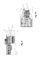
- FIG. 6 is a side view of the retractor shown in FIGS. 2, 4, and 5 , but with the outer cover removed, and the lock-down arm flipped down, for locking the retractor;
- FIG. 7 is a view like FIG. 6 , but shows the lock-down arm disengaged
- FIG. 8 is an unexploded side view of the mechanism shown in FIG. 1 , and also illustrates mounting of the mechanism to the underside of a shelf;
- FIG. 9 is a view similar to FIG. 8 ;
- FIG. 10 is a bottom view of the mechanism shown in FIGS. 1, 3, 8, and 9 .
- arrow 10 generally refers to a retractor that is used in connection with a retail anti-theft display.
- the retractor 10 has a spool 12 for winding or unwinding the retractor's tether cable 22 (for tether retraction or extension).
- the spool 12 has teeth around its outer periphery (best seen at 14 in FIGS. 6 and 7 ).
- a lever or lock arm 16 is mounted for rotation about a pin 18 (described later). While the lock arm 16 may take many forms, it has a projecting portion 20 that is sized to engage a lock-down mechanism (described later) with the teeth 14 on the spool 12 , when the lock arm 16 is “flipped down.”
- the lock arm 16 may be flipped back and forth between the position shown in FIGS. 4 and 5 , respectively, depending on whether it is desired to lock or unlock the spool 12 and cable 22 .
- the lock arm 16 is designed to have a type of camming/locking action, further described below.
- the lock arm 16 is flipped “down” so that the teeth 14 on spool 12 are engaged. This, in turn, locks the spool against rotation and holds the retractor cable 22 in place, locking it from further extension or retraction.
Landscapes
- Engineering & Computer Science (AREA)
- General Engineering & Computer Science (AREA)
- Mechanical Engineering (AREA)
- Burglar Alarm Systems (AREA)
Abstract
Description
Claims (9)
Priority Applications (2)
| Application Number | Priority Date | Filing Date | Title |
|---|---|---|---|
| US14/963,129 US10464780B2 (en) | 2014-12-09 | 2015-12-08 | Tether lock |
| US16/668,462 US10974926B2 (en) | 2014-12-09 | 2019-10-30 | Tether lock |
Applications Claiming Priority (2)
| Application Number | Priority Date | Filing Date | Title |
|---|---|---|---|
| US201462089760P | 2014-12-09 | 2014-12-09 | |
| US14/963,129 US10464780B2 (en) | 2014-12-09 | 2015-12-08 | Tether lock |
Related Child Applications (1)
| Application Number | Title | Priority Date | Filing Date |
|---|---|---|---|
| US16/668,462 Division US10974926B2 (en) | 2014-12-09 | 2019-10-30 | Tether lock |
Publications (2)
| Publication Number | Publication Date |
|---|---|
| US20160159611A1 US20160159611A1 (en) | 2016-06-09 |
| US10464780B2 true US10464780B2 (en) | 2019-11-05 |
Family
ID=56093640
Family Applications (2)
| Application Number | Title | Priority Date | Filing Date |
|---|---|---|---|
| US14/963,129 Active 2037-03-08 US10464780B2 (en) | 2014-12-09 | 2015-12-08 | Tether lock |
| US16/668,462 Active US10974926B2 (en) | 2014-12-09 | 2019-10-30 | Tether lock |
Family Applications After (1)
| Application Number | Title | Priority Date | Filing Date |
|---|---|---|---|
| US16/668,462 Active US10974926B2 (en) | 2014-12-09 | 2019-10-30 | Tether lock |
Country Status (1)
| Country | Link |
|---|---|
| US (2) | US10464780B2 (en) |
Cited By (3)
| Publication number | Priority date | Publication date | Assignee | Title |
|---|---|---|---|---|
| US10974926B2 (en) | 2014-12-09 | 2021-04-13 | Mobile Tech, Inc. | Tether lock |
| US11295585B2 (en) | 2014-01-22 | 2022-04-05 | Invue Security Products Inc. | Systems and methods for remotely controlling security devices |
| US11598126B2 (en) * | 2019-11-01 | 2023-03-07 | Mobile Tech, Inc. | Product merchandising systems with enhanced security features |
Families Citing this family (2)
| Publication number | Priority date | Publication date | Assignee | Title |
|---|---|---|---|---|
| CN207461843U (en) * | 2015-10-12 | 2018-06-08 | Invue安全产品公司 | For the coil winder of commodity security system |
| WO2018102403A1 (en) * | 2016-11-30 | 2018-06-07 | Invue Security Products | Recoiling cable wrap |
Citations (19)
| Publication number | Priority date | Publication date | Assignee | Title |
|---|---|---|---|---|
| US3853283A (en) * | 1973-06-04 | 1974-12-10 | J Croce | Retractable leash device |
| US6799994B2 (en) | 1998-03-16 | 2004-10-05 | Telefonix, Inc | Cord management apparatus and method |
| US7207296B2 (en) * | 2005-03-14 | 2007-04-24 | Didonato Pietro | No-tangle two dog retractable leash with flashlight |
| US7866282B2 (en) * | 2005-05-05 | 2011-01-11 | Terence Earl Simpson | Animal restraint apparatus and related methods |
| US8251020B2 (en) * | 2010-03-12 | 2012-08-28 | Unleashed Products, LLC | Leash having a speed-limiting braking mechanism and system and method for using same |
| US20130026322A1 (en) | 2011-07-25 | 2013-01-31 | Merchandising Technologies, Inc. | Rotational Mount For Hand-Held Electronics |
| US20130161054A1 (en) | 2011-12-21 | 2013-06-27 | Merchandising Technologies, Inc. | Security/Tether Cable |
| US8558688B2 (en) | 2010-06-21 | 2013-10-15 | Mobile Tech, Inc. | Display for hand-held electronics |
| US8698618B2 (en) | 2010-06-21 | 2014-04-15 | Mobile Tech, Inc. | Display for hand-held electronics |
| US8955807B2 (en) | 2010-08-18 | 2015-02-17 | Mobile Tech, Inc. | Security bracket |
| US9092960B2 (en) | 2011-05-05 | 2015-07-28 | Mobile Tech, Inc. | Retail security system |
| WO2015112336A1 (en) | 2014-01-22 | 2015-07-30 | Invue Security Products Inc. | Systems and methods for remotely controlling security devices |
| US9097380B2 (en) | 2010-08-11 | 2015-08-04 | Mobile Tech, Inc. | Adjustable security bracket |
| US20150333454A1 (en) | 2014-05-15 | 2015-11-19 | Mobile Tech, Inc. | Adaptor cable for retail display of electronic device |
| US9437088B2 (en) | 2013-09-29 | 2016-09-06 | Invue Security Products Inc. | Systems and methods for protecting retail display merchandise from theft |
| US9443404B2 (en) | 2014-02-14 | 2016-09-13 | Invue Security Products Inc. | Tethered security system with wireless communication |
| WO2017066114A1 (en) | 2015-10-12 | 2017-04-20 | Invue Security Products Inc. | Recoiler for a merchandise security system |
| US9786140B2 (en) | 2010-06-21 | 2017-10-10 | Mobile Tech, Inc. | Display for hand-held electronics |
| US20180049563A1 (en) | 2009-01-10 | 2018-02-22 | Mti, Inc | Display for Hand-Held Electronics |
Family Cites Families (6)
| Publication number | Priority date | Publication date | Assignee | Title |
|---|---|---|---|---|
| US5513785A (en) * | 1994-03-21 | 1996-05-07 | Campagna, Jr.; Gerald P. | Gun retention system |
| CA2664237C (en) * | 2009-04-27 | 2016-12-06 | Joel Ferguson | Modular hand-held electronic device charging and monitoring system |
| US8985541B2 (en) * | 2010-06-11 | 2015-03-24 | Sennco Solutions | Cable roller, system and/or method for extending and/or retracting a coiled cable |
| CN202773708U (en) * | 2012-09-19 | 2013-03-13 | 施福有 | Warped plate type button switch device of dog holding device |
| US10464780B2 (en) | 2014-12-09 | 2019-11-05 | Mobile Tech, Inc. | Tether lock |
| US9488433B2 (en) * | 2015-09-03 | 2016-11-08 | Timothy L Greenwood | Sling recoiling gun stock |
-
2015
- 2015-12-08 US US14/963,129 patent/US10464780B2/en active Active
-
2019
- 2019-10-30 US US16/668,462 patent/US10974926B2/en active Active
Patent Citations (30)
| Publication number | Priority date | Publication date | Assignee | Title |
|---|---|---|---|---|
| US3853283A (en) * | 1973-06-04 | 1974-12-10 | J Croce | Retractable leash device |
| US6799994B2 (en) | 1998-03-16 | 2004-10-05 | Telefonix, Inc | Cord management apparatus and method |
| US7207296B2 (en) * | 2005-03-14 | 2007-04-24 | Didonato Pietro | No-tangle two dog retractable leash with flashlight |
| US7866282B2 (en) * | 2005-05-05 | 2011-01-11 | Terence Earl Simpson | Animal restraint apparatus and related methods |
| US10026281B2 (en) | 2009-01-10 | 2018-07-17 | Mobile Tech, Inc. | Display for hand-held electronics |
| US20180049563A1 (en) | 2009-01-10 | 2018-02-22 | Mti, Inc | Display for Hand-Held Electronics |
| US8251020B2 (en) * | 2010-03-12 | 2012-08-28 | Unleashed Products, LLC | Leash having a speed-limiting braking mechanism and system and method for using same |
| US9786140B2 (en) | 2010-06-21 | 2017-10-10 | Mobile Tech, Inc. | Display for hand-held electronics |
| US8558688B2 (en) | 2010-06-21 | 2013-10-15 | Mobile Tech, Inc. | Display for hand-held electronics |
| US8698617B2 (en) | 2010-06-21 | 2014-04-15 | Mobile Tech, Inc. | Display for hand-held electronics |
| US8698618B2 (en) | 2010-06-21 | 2014-04-15 | Mobile Tech, Inc. | Display for hand-held electronics |
| US9097380B2 (en) | 2010-08-11 | 2015-08-04 | Mobile Tech, Inc. | Adjustable security bracket |
| US8955807B2 (en) | 2010-08-18 | 2015-02-17 | Mobile Tech, Inc. | Security bracket |
| US9092960B2 (en) | 2011-05-05 | 2015-07-28 | Mobile Tech, Inc. | Retail security system |
| US20130026322A1 (en) | 2011-07-25 | 2013-01-31 | Merchandising Technologies, Inc. | Rotational Mount For Hand-Held Electronics |
| US20130161054A1 (en) | 2011-12-21 | 2013-06-27 | Merchandising Technologies, Inc. | Security/Tether Cable |
| US9437088B2 (en) | 2013-09-29 | 2016-09-06 | Invue Security Products Inc. | Systems and methods for protecting retail display merchandise from theft |
| WO2015112336A1 (en) | 2014-01-22 | 2015-07-30 | Invue Security Products Inc. | Systems and methods for remotely controlling security devices |
| US20160335859A1 (en) | 2014-01-22 | 2016-11-17 | Invue Security Products Inc. | Systems and methods for remotely controlling security devices |
| US9811988B2 (en) | 2014-02-14 | 2017-11-07 | Invue Security Products Inc. | Tethered security system with wireless communication |
| US9443404B2 (en) | 2014-02-14 | 2016-09-13 | Invue Security Products Inc. | Tethered security system with wireless communication |
| US10078945B2 (en) | 2014-02-14 | 2018-09-18 | Invue Security Products Inc. | Tethered security system with wireless communication |
| US20150333454A1 (en) | 2014-05-15 | 2015-11-19 | Mobile Tech, Inc. | Adaptor cable for retail display of electronic device |
| US9761101B2 (en) | 2015-10-12 | 2017-09-12 | Invue Security Products Inc. | Recoiler for a merchandise security system |
| US9747765B1 (en) | 2015-10-12 | 2017-08-29 | Invue Security Products Inc. | Recoiler for a merchandise security system |
| US9805564B1 (en) | 2015-10-12 | 2017-10-31 | Invue Security Products Inc. | Recoiler for a merchandise security system |
| WO2017066114A1 (en) | 2015-10-12 | 2017-04-20 | Invue Security Products Inc. | Recoiler for a merchandise security system |
| US9928704B2 (en) | 2015-10-12 | 2018-03-27 | Invue Security Products Inc. | Recoiler for a merchandise security system |
| US10043358B1 (en) | 2015-10-12 | 2018-08-07 | Invue Security Products Inc. | Recoiler for a merchandise security system |
| US10068444B1 (en) | 2015-10-12 | 2018-09-04 | Invue Security Products Inc. | Recoiler for a merchandise security system |
Non-Patent Citations (15)
| Title |
|---|
| Freedom LP3 brochure, MTI, Sep. 2009, 1 page. |
| Freedom LP3 Product Manual, MTI, Mar. 2010, pp. 1-20. |
| Freedom LP3 Product Manual, MTI, Mar. 2011, pp. 1-25. |
| Freedom One Product Manual, MTI, Jun. 2011, pp. 1-32. |
| Freedom One Product Manual, MTI, Jun. 2012, pp. 1-32. |
| Freedom Universal 2.0 Product Manual, MTI, Dec. 2008, pp. 1-21. |
| Propelinteractive, "MTI LP3 Product Mounting", YouTube Video https://www.youtube.com/watch?v=KX4TEuj1jCl, published on Jun. 23, 2010 (see sample screenshots, pp. 1-11). |
| Protex International Corp., "Instructions for PowerPro Detangler", 2005, 1 page. |
| Protex International Corp., "Instructions for PowerPro Sensor Head Cameras and Camcorders (Power and Security)", 2007, pp. 1-9. |
| Protex International Corp., "PowerPro System", 2006, pp. 1-2. |
| U.S. Appl. No. 61/930,039, filed Jan. 22, 2014. |
| U.S. Appl. No. 61/939,954, filed Feb. 14, 2014. |
| U.S. Appl. No. 61/974,058, filed Apr. 2, 2014. |
| U.S. Appl. No. 62/240,171, filed Oct. 12, 2015. |
| U.S. Appl. No. 62/297,215, filed Feb. 19, 2016. |
Cited By (3)
| Publication number | Priority date | Publication date | Assignee | Title |
|---|---|---|---|---|
| US11295585B2 (en) | 2014-01-22 | 2022-04-05 | Invue Security Products Inc. | Systems and methods for remotely controlling security devices |
| US10974926B2 (en) | 2014-12-09 | 2021-04-13 | Mobile Tech, Inc. | Tether lock |
| US11598126B2 (en) * | 2019-11-01 | 2023-03-07 | Mobile Tech, Inc. | Product merchandising systems with enhanced security features |
Also Published As
| Publication number | Publication date |
|---|---|
| US20200062534A1 (en) | 2020-02-27 |
| US10974926B2 (en) | 2021-04-13 |
| US20160159611A1 (en) | 2016-06-09 |
Similar Documents
| Publication | Publication Date | Title |
|---|---|---|
| US10974926B2 (en) | Tether lock | |
| US7866713B2 (en) | Locker structure | |
| US7302816B1 (en) | Combined computer security lock and security cable | |
| JP6247635B2 (en) | Multiple lock system for luggage cases | |
| CN101663450B (en) | Cable wrap security device | |
| AU2010249905B2 (en) | Cable wrap security device | |
| US10858865B2 (en) | Anti-theft device with adjustable locking arms for securing an article of merchandise | |
| US4738341A (en) | Lock system for a suitcase or container | |
| US11407610B2 (en) | Equipment tether | |
| US9404291B1 (en) | Device and method for an alarming strap tag | |
| US20080035778A1 (en) | Swivel recoiler | |
| US8782917B2 (en) | Disc brake for a tape measure | |
| US8683710B2 (en) | Tape measure tool with lanyard | |
| US20150000613A1 (en) | Pet leash with padlock | |
| US20180340357A1 (en) | Package wrap | |
| AU2014279845B2 (en) | Security device | |
| US4417758A (en) | Remotely releasable choker | |
| US20070119219A1 (en) | Computer lock and corresponding security hole pattern | |
| US9943152B2 (en) | Lockable lidded containers | |
| WO2013110459A1 (en) | Closing device for closing and securing a receiving device | |
| EP2958846B1 (en) | Improved remote sling release for crane | |
| US8888422B2 (en) | Locking system for roll-off containers | |
| US9328864B1 (en) | Carrier device for display device | |
| US11696628B2 (en) | Key organizer | |
| US9805563B2 (en) | Security device |
Legal Events
| Date | Code | Title | Description |
|---|---|---|---|
| AS | Assignment |
Owner name: MOBILE TECH, INC., OREGON Free format text: ASSIGNMENT OF ASSIGNORS INTEREST;ASSIGNOR:WHEELER, WADE;REEL/FRAME:038366/0587 Effective date: 20160120 |
|
| AS | Assignment |
Owner name: PNC BANK, NATIONAL ASSOCIATION, PENNSYLVANIA Free format text: SECURITY INTEREST;ASSIGNOR:MOBILE TECH, INC.;REEL/FRAME:039370/0989 Effective date: 20160805 |
|
| STPP | Information on status: patent application and granting procedure in general |
Free format text: FINAL REJECTION MAILED |
|
| STPP | Information on status: patent application and granting procedure in general |
Free format text: AMENDMENT AFTER NOTICE OF APPEAL |
|
| STPP | Information on status: patent application and granting procedure in general |
Free format text: NOTICE OF ALLOWANCE MAILED -- APPLICATION RECEIVED IN OFFICE OF PUBLICATIONS |
|
| AS | Assignment |
Owner name: MOBILE TECH, INC., OREGON Free format text: ASSIGNMENT OF ASSIGNORS INTEREST;ASSIGNOR:CHARLESWORTH, ERIC;REEL/FRAME:049977/0889 Effective date: 20190806 |
|
| STPP | Information on status: patent application and granting procedure in general |
Free format text: PUBLICATIONS -- ISSUE FEE PAYMENT VERIFIED |
|
| STCF | Information on status: patent grant |
Free format text: PATENTED CASE |
|
| MAFP | Maintenance fee payment |
Free format text: PAYMENT OF MAINTENANCE FEE, 4TH YEAR, LARGE ENTITY (ORIGINAL EVENT CODE: M1551); ENTITY STATUS OF PATENT OWNER: LARGE ENTITY Year of fee payment: 4 |